EP3281820B1 - Dispositif d'alimentation de construction de station - Google Patents
Dispositif d'alimentation de construction de station Download PDFInfo
- Publication number
- EP3281820B1 EP3281820B1 EP17193969.7A EP17193969A EP3281820B1 EP 3281820 B1 EP3281820 B1 EP 3281820B1 EP 17193969 A EP17193969 A EP 17193969A EP 3281820 B1 EP3281820 B1 EP 3281820B1
- Authority
- EP
- European Patent Office
- Prior art keywords
- power
- capacitor unit
- soc
- unit
- station
- Prior art date
- Legal status (The legal status is an assumption and is not a legal conclusion. Google has not performed a legal analysis and makes no representation as to the accuracy of the status listed.)
- Active
Links
Images


Classifications
-
- H—ELECTRICITY
- H02—GENERATION; CONVERSION OR DISTRIBUTION OF ELECTRIC POWER
- H02J—ELECTRIC POWER NETWORKS; CIRCUIT ARRANGEMENTS OR SYSTEMS FOR SUPPLYING OR DISTRIBUTING ELECTRIC POWER; SYSTEMS FOR STORING ELECTRIC ENERGY
- H02J3/00—Circuit arrangements for AC mains or AC distribution networks
-
- B—PERFORMING OPERATIONS; TRANSPORTING
- B60—VEHICLES IN GENERAL
- B60M—POWER SUPPLY LINES, AND DEVICES ALONG RAILS, FOR ELECTRICALLY- PROPELLED VEHICLES
- B60M3/00—Feeding power to supply lines in contact with collector on vehicles; Arrangements for consuming regenerative power
- B60M3/06—Arrangements for consuming regenerative power
-
- H—ELECTRICITY
- H02—GENERATION; CONVERSION OR DISTRIBUTION OF ELECTRIC POWER
- H02M—APPARATUS FOR CONVERSION BETWEEN AC AND AC, BETWEEN AC AND DC, OR BETWEEN DC AND DC, AND FOR USE WITH MAINS OR SIMILAR POWER SUPPLY SYSTEMS; CONVERSION OF DC OR AC INPUT POWER INTO SURGE OUTPUT POWER; CONTROL OR REGULATION THEREOF
- H02M3/00—Conversion of DC power input into DC power output
- H02M3/02—Conversion of DC power input into DC power output without intermediate conversion into AC
- H02M3/04—Conversion of DC power input into DC power output without intermediate conversion into AC by static converters
-
- H—ELECTRICITY
- H02—GENERATION; CONVERSION OR DISTRIBUTION OF ELECTRIC POWER
- H02M—APPARATUS FOR CONVERSION BETWEEN AC AND AC, BETWEEN AC AND DC, OR BETWEEN DC AND DC, AND FOR USE WITH MAINS OR SIMILAR POWER SUPPLY SYSTEMS; CONVERSION OF DC OR AC INPUT POWER INTO SURGE OUTPUT POWER; CONTROL OR REGULATION THEREOF
- H02M7/00—Conversion of AC power input into DC power output; Conversion of DC power input into AC power output
- H02M7/42—Conversion of DC power input into AC power output without possibility of reversal
- H02M7/44—Conversion of DC power input into AC power output without possibility of reversal by static converters
Definitions
- the present invention relates to a station-building power supply device that supplies power to electrical facilities (hereinafter, "station load”) such as an air-conditioning system, a lighting system, and an elevator in a station yard using both AC power supplied from an AC system and the surplus regenerative power of trains.
- station load electrical facilities
- air-conditioning system a lighting system
- elevator an elevator in a station yard using both AC power supplied from an AC system and the surplus regenerative power of trains.
- regenerative power generated by regenerative brakes of trains is used as running power for other trains via a feeder in a DC feeding network.
- a feeding voltage increases when the regenerative power exceeds the running power in the same transformation zone, and the feeding voltage decreases when the regenerative power falls below the running power.
- Patent Literature 1 shows a control system of a power storage device for direct current electric railway.
- Patent Literature 3 shows a control device and a control method.
- Patent Literature 4 shows a railway feeding system.
- the present invention has been achieved in view of the above problem, and an objective of the present invention is to provide a station-building power supply device that can effectively use surplus regenerative power while suppressing fluctuations in the power amount of an AC system that supplies AC power to a station load.
- a station-building power supply device that supplies power to a station load using both AC power supplied from an AC system and surplus regenerative power generated by trains.
- the station-building power supply device includes a feeding-voltage detection unit that detects a feeding voltage; a capacitor unit that stores therein the surplus regenerative power; an SOC (State Of Charge) detection unit that detects an SOC of the capacitor unit; a first power conversion unit that performs DC/DC power conversion in both directions between a feeder and the capacitor unit; a second power conversion unit that converts DC power supplied from the capacitor unit to AC power and supplies the AC power to the station load; and a control unit that controls the first power conversion unit and the second power conversion unit on the basis of the feeding voltage and the SOC.
- a feeding-voltage detection unit that detects a feeding voltage
- a capacitor unit that stores therein the surplus regenerative power
- an SOC (State Of Charge) detection unit that detects an SOC of the capacitor unit
- a first power conversion unit that performs DC/DC power conversion in both directions between a feeder and the capacitor unit
- a second power conversion unit that converts DC power supplied from the capacitor unit to AC power and supplies the AC
- the control unit controls the first power conversion unit such that power is supplied from the feeder to the capacitor unit when the feeding voltage exceeds a predetermined first voltage threshold, and controls the second power conversion unit such that power is supplied from the capacitor unit to the station load when the SOC exceeds a predetermined first SOC threshold.
- surplus regenerative power can be effectively used while suppressing fluctuations in the power amount of an AC system that supplies AC power to a station load.
- FIG. 1 is a diagram illustrating an example configuration of a station-building power supply device according to an embodiment of the present invention.
- a transformer 3 that transforms high-voltage AC power supplied from an AC system 1 (an AC6600 V system in this example) into low-voltage AC power (an AC210 V system in this example) is provided in a station electrical room (not illustrated) or the like, and power is supplied to electrical facilities 4-1, 4-2, ⁇ and 4-n (hereinafter, "station loads 4") such as an air-conditioning system, a lighting system, and an elevator in the station yard.
- a station-building power supply device 100 is configured to transform surplus regenerative power that has not been consumed in an electrical transformation zone in which trains 5 run into low-voltage AC power and to supply the AC power to the station loads 4. That is, the station loads 4 are supplied with both the AC power supplied from the AC system 1 and the surplus regenerative power in the electrical transformation zone.
- the station-building power supply device 100 includes a feeding-voltage detection unit 8 that detects a feeding voltage (a DC1500 V system, in this example) between a feeder 6 and a rail 7; a capacitor unit 9 that stores therein the surplus regenerative power generated in the electrical transformation zone in which the trains 5 run; an SOC detection unit 10 that detects an SOC (State Of Charge) of the capacitor unit 9; a first power conversion unit 11 including a bidirectional DC/DC converter 21 that performs DC/DC power conversion in both directions between the feeder 6 and the capacitor unit 9; a second power conversion unit 12 including an inverter 22 that converts DC power supplied from the capacitor unit 9 to AC power and a transformer 23 that converts an output from the inverter 22 into AC power (the AC210 V system in this example) to be supplied to the station loads 4; and a control unit 13 that controls the first power conversion unit 11 and the second power conversion unit 12 on the basis of the feeding voltage and the SOC of the capacitor unit 9.
- a feeding-voltage detection unit 8 that detects
- a known method can be used by the SOC detection unit 10 as a method of detecting the SOC, and the present invention is not limited by the method of detecting the SOC.
- the present invention is not limited by the circuit configuration of the bidirectional DC/DC converter 21 that constitutes the first power conversion unit 11 nor by the circuit configuration of the inverter 22 that constitutes the second power conversion unit 12.
- a voltage threshold for the feeding voltage
- an SOC State Of Charge
- a first SOC threshold for the SOC of the capacitor unit 9
- a value that indicates the occurrence of surplus regenerative power in the electrical transformation zone is set as the first voltage threshold and, when the feeding voltage exceeds the first voltage threshold, the control unit 13 controls the first power conversion unit 11 such that power is supplied from the feeder 6 to the capacitor unit 9, thereby charging the capacitor unit 9.
- a value for indicating whether the capacitor unit 9 can discharge is set as the first SOC threshold, and when the SOC of the capacitor unit 9 exceeds the first SOC threshold, the control unit 13 controls the second power conversion unit 12 such that it supplies power from the capacitor unit 9 to the station loads 4.
- the capacitor unit 9 is charged with the surplus regenerative power, and power supplied continuously from the AC system 1 to the station loads 4 can be supplemented with the surplus regenerative power charged in the capacitor unit 9, while the capacitor unit 9 maintains an SOC that enables discharging.
- the surplus regenerative power can be effectively used while fluctuations in the voltage of the feeder 6 and fluctuations in the amount of power supplied from the AC system 1 are reduced.
- the second power conversion unit 12 is also controlled so as to cause the amount of power supplied from the capacitor unit 9 to the station loads 4 to be substantially constant and accordingly the amount of power supplied from the AC system 1 can be more stable.
- a second voltage threshold smaller than the first voltage threshold can be provided for the feeding voltage
- a second SOC threshold larger than the first SOC threshold can be provided for the SOC of the capacitor unit 9.
- a value for indicating a shortage of power in the electrical transformation zone is set as the second voltage threshold and a value for indicating whether the capacitor unit 9 can supplement a power shortage in the electrical transformation zone is set as the second SOC threshold.
- the control unit 13 can control the first power conversion unit such that it supplies power from the capacitor unit 9 to the feeder 6.
- the capacitor unit 9 maintains an SOC that enables supplementation of a power shortage in the electrical transformation zone
- the power shortage in the electrical transformation zone can be supplemented with the surplus regenerative power with which the capacitor unit 9 has been charged. Accordingly, fluctuations in the voltage of the feeder 6 can be more stable.
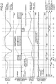
- FIGS. 2 are diagrams illustrating an example of time charts of the station-building power supply device according to the present embodiment.
- FIG. 2(a) illustrates transition of the feeding voltage and FIG. 2(b) illustrates transition of charge/discharge power of the capacitor unit 9.
- FIG. 2(c) illustrates transition of the SOC of the capacitor unit 9, and
- FIG. 2(d) illustrates power consumption by the station loads 4.
- the example illustrated in FIGS. 2 is an example in which a constant power charging method is used as a method of charging the capacitor unit 9. In the illustrated example, discharging from the capacitor unit 9 to the feeder 6 is also performed at a constant power.
- the present invention is not limited by the method of charging the capacitor unit 9 or the method of discharging from the capacitor unit 9 to the feeder 6.
- the feeding voltage is within a range from the second voltage threshold to the first voltage threshold ( FIG. 2(a) ) and the SOC of the capacitor unit 9 is above the first SOC threshold ( FIG. 2(c) ). Therefore, the control unit 13 operates the second power conversion unit 12 such that it turns ON discharging from the capacitor unit 9 to the station loads 4. At that time, the control unit 13 controls the second power conversion unit 12 such that it causes the amount of power supplied from the capacitor unit 9 to the station loads 4 to be substantially constant ( FIG. 2(b) ).
- the control unit 13 gradually decreases the amount of power supplied from the capacitor unit 9 to the station loads 4, causing the power amount supplied from the capacitor unit 9 to the station loads 4 to be substantially zero at a time t2', and stops the operation of the second power conversion unit 12 such that the discharging from the capacitor unit 9 to the station loads 4 is turned off.
- the control unit 13 When the feeding voltage exceeds the first voltage threshold at a time t3 ( FIG. 2(a) ), the control unit 13 operates the first power conversion unit 11 such that it turns ON charging from the feeder 6 to the capacitor unit 9.
- the control unit 13 operates the second power conversion unit 12 such that it turns ON discharging from the capacitor unit 9 to the station loads 4 to gradually increase the power amount supplied from the capacitor unit 9 to the station loads 4 and controls the second power conversion unit 12 such that it causes the power amount supplied from the capacitor unit 9 to the station loads 4 to be substantially constant after a time t3" ( FIG. 2(b) ).
- the SOC of the capacitor unit 9 increases due to charging from the feeder 6 to the capacitor unit 9 ( FIG. 2(c) ). Meanwhile, the feeding value becomes lower (indicated by a solid line in FIG. 2(a) ) than that in a case where the charging to the capacitor unit 9 is not performed (indicated by a dashed line in FIG. 2(a) ).
- the control unit 13 stops the operation of the first power conversion unit 11 so as to turn OFF the charging from the feeder 6 to the capacitor unit 9.
- the control unit 13 When the feeding voltage exceeds the first voltage threshold at the time t7 ( FIG. 2(a) ), the control unit 13 operates the first power conversion unit 11 such that it turns ON charging from the feeder 6 to the capacitor unit 9.
- the charging from the feeder 6 to the capacitor unit 9 is performed similar to in the period from the time t3 to the time t4 and thus the SOC of the capacitor unit 9 increases ( FIG. 2(c) ).
- the feeding voltage accordingly becomes lower (indicated by a solid line in FIG. 2(a) ) than that in a case where the charging of the capacitor unit 9 is not performed (indicated by a dashed line in FIG. 2(a) ).
- the control unit 13 stops the operation of the first power conversion unit 11 such that it turns OFF the charging from the feeder 6 to the capacitor unit 9.
- the feeding voltage is within the range from the second voltage threshold to the first voltage threshold ( FIG. 2(a) ) and the SOC of the capacitor unit 9 is above the first SOC threshold ( FIG. 2(c) ). Therefore, only discharging from the capacitor unit 9 to the station loads 4 is performed and thus the SOC of the capacitor unit 9 gradually decreases ( FIG. 2(c) ).
- the control unit 13 When the feeding voltage falls below the second voltage threshold at the time t9 ( FIG. 2(a) ), the control unit 13 operates the first power conversion unit 11 to turn ON discharging from the capacitor unit 9 to the feeder 6.
- the feeding voltage is below the second voltage threshold ( FIG. 2(a) ) and the SOC of the capacitor unit 9 is above the second SOC threshold ( FIG. 2(c) ) unlike in the period from the time t5 to the time t6. Therefore, the discharging from the capacitor unit 9 to the station loads 4 and discharging from the capacitor unit 9 to the feeder 6 are performed simultaneously, so that the SOC of the capacitor unit 9 decreases more ( FIG. 2(c) ) and the feeding voltage becomes higher (indicated by a solid line in FIG. 2(a) ) than that in a case where discharging to the capacitor unit 9 is not performed (indicated by a dashed line in FIG. 2(a) ).
- the control unit 13 stops the operation of the first power conversion unit 11 to turn OFF the discharging from the capacitor unit 9 to the feeder 6.
- the control unit 13 When the feeding voltage exceeds the first voltage threshold at the time t12 ( FIG. 2(a) ), the control unit 13 operates the first power conversion unit 11 to turn ON charging from the feeder 6 to the capacitor unit 9.
- charging from the feeder 6 to the capacitor unit 9 is performed similar to in the period from the time t3 to the time t4, so that the SOC of the capacitor unit 9 increases ( FIG. 2(c) ) and the feeding voltage becomes lower (indicated by a solid line in FIG. 2(a) ) than that in a case where the charging to the capacitor unit 9 is not performed (indicated by a dashed line in FIG. 2(a) ).
- surplus regenerative power which has been charge in the capacitor unit 9 in a period in which the feeding voltage is above the first voltage threshold, is supplied to the station loads 4 at a substantially constant power amount, except for a period in which the SOC of the capacitor unit 9 is below the first SOC threshold.
- FIGS. 3 are diagrams illustrating an example of time charts of a conventional station-building power supply device not including a capacitor unit that stores therein surplus regenerative power.
- FIG. 3(a) illustrates transition of a feeding voltage
- FIG. 3(b) illustrates power consumption of station loads.
- the surplus regenerative power occurring intermittently is stored in the capacitor unit 9 and power supplied continuously from the AC system 1 to the station loads 4 is supplemented with the surplus regenerative power stored in the capacitor unit 9, in a period in which the capacitor unit 9 maintains an SOC that enables discharging. Therefore, the surplus regenerative power can be effectively used while fluctuations in the total power amount of the AC system 1 are suppressed.
- the station-building power supply device includes the capacitor unit that stores therein surplus regenerative power in an electrical transformation zone; the first power conversion unit that performs DC/DC power conversion in both directions between the feeder and the capacitor unit; and the second power conversion unit that converts DC power supplied from the capacitor unit to AC power to be supplied to the station loads.
- a voltage threshold (a first voltage threshold) for the feeding voltage and an SOC threshold (a first SOC threshold) for the SOC of the capacitor unit are set; a value that indicates occurrence of surplus regenerative power in the electrical transformation zone is set as the first voltage threshold; and a value that indicates whether the capacitor unit can discharge is set as the first SOC threshold.
- the first power conversion unit is controlled so as to supply power from the feeder to the capacitor unit to perform charging of the capacitor unit when the feeding voltage exceeds the first voltage threshold; and the second power conversion unit is controlled so as to supply power from the capacitor unit to the station loads when the SOC of the capacitor unit exceeds the first SOC threshold. Therefore, each time generation of surplus regenerative power in the electrical transformation zone occurs, the capacitor unit is charged with the surplus regenerative power, and power supplied continuously from the AC system to the station loads can be supplemented with the surplus regenerative power with which the capacitor unit has been charged in a period in which the capacitor unit maintains an SOC that enables discharging. Accordingly, the surplus regenerative power can be effectively used while fluctuations in the voltage of the feeder and fluctuations in the amount of power supplied from the AC system are suppressed.
- the second power conversion unit is controlled so as to cause the amount of power supplied from the capacitor unit to the station loads to be substantially constant. Accordingly, the amount of power supplied from the AC system can be more stable.
- the second voltage threshold smaller than the first voltage threshold is provided for the feeding voltage
- the second SOC threshold larger than the first SOC threshold is provided for the SOC of the capacitor unit.
- a value that indicates a shortage of power in the electrical transformation zone is set as the second voltage threshold
- a value that indicates whether the capacitor unit can supplement a power shortage in the electrical transformation zone is set as the second SOC threshold.
- the capacitor unit maintains an SOC that enables supplementation of a power shortage in the electrical transformation zone
- the power shortage in the electrical transformation zone can be supplemented with surplus regenerative power with which the capacitor unit has been charged. Accordingly, voltage fluctuations of the feeder can be more stable.
Landscapes
- Engineering & Computer Science (AREA)
- Power Engineering (AREA)
- Mechanical Engineering (AREA)
- Charge And Discharge Circuits For Batteries Or The Like (AREA)
- Supply And Distribution Of Alternating Current (AREA)
- Inverter Devices (AREA)
Claims (1)
- Dispositif d'alimentation de construction de station (100) qui alimente en énergie une charge de station (4) en utilisant à la fois l'énergie à courant alternatif fournie par un système à courant alternatif (1) et de l'énergie régénératrice excédentaire générée par des trains (5), le dispositif d'alimentation de construction de station (100) comprenant :une unité de détection de tension d'alimentation (8) qui détecte une tension d'alimentation ;une unité de détection de SOC (état de charge) (10) qui détecte un SOC d'une unité à condensateur (9) stockant dans celle-ci l'énergie régénératrice excédentaire ;une première unité de conversion de courant (11) qui effectue une conversion de courant continu/continu dans les deux sens entre une ligne d'alimentation (6) et l'unité à condensateur (9) ;une seconde unité de conversion de courant (12) qui convertit le courant continu fourni par l'unité à condensateur (9) en courant alternatif et fournit le courant alternatif à la charge de station (4) ; etune unité de commande (13) qui commande la première unité de conversion de courant (11) et la seconde unité de conversion de courant (12) sur la base de la tension d'alimentation et du SOC, dans lequell'unité de commande (13)commande, lorsque le SOC dépasse un premier seuil de SOC prédéterminé, la seconde unité de conversion de courant (12) de manière à ce que le courant soit fourni par l'unité à condensateur (9) à la charge de station (4), etcommande, lorsque le SOC dépasse un second seuil de SOC qui est supérieur au premier seuil de SOC, la première unité de conversion de courant (11) de manière à ce qu'un courant soit fourni par l'unité à condensateur (9) à la ligne d'alimentation (6).
Priority Applications (1)
| Application Number | Priority Date | Filing Date | Title |
|---|---|---|---|
| EP17193969.7A EP3281820B1 (fr) | 2013-11-28 | 2013-11-28 | Dispositif d'alimentation de construction de station |
Applications Claiming Priority (3)
| Application Number | Priority Date | Filing Date | Title |
|---|---|---|---|
| PCT/JP2013/082109 WO2015079544A1 (fr) | 2013-11-28 | 2013-11-28 | Dispositif d'alimentation électrique de bâtiment de gare |
| EP13898230.1A EP3075596B1 (fr) | 2013-11-28 | 2013-11-28 | Dispositif d'alimentation électrique de bâtiment de gare |
| EP17193969.7A EP3281820B1 (fr) | 2013-11-28 | 2013-11-28 | Dispositif d'alimentation de construction de station |
Related Parent Applications (2)
| Application Number | Title | Priority Date | Filing Date |
|---|---|---|---|
| EP13898230.1A Division-Into EP3075596B1 (fr) | 2013-11-28 | 2013-11-28 | Dispositif d'alimentation électrique de bâtiment de gare |
| EP13898230.1A Division EP3075596B1 (fr) | 2013-11-28 | 2013-11-28 | Dispositif d'alimentation électrique de bâtiment de gare |
Publications (2)
| Publication Number | Publication Date |
|---|---|
| EP3281820A1 EP3281820A1 (fr) | 2018-02-14 |
| EP3281820B1 true EP3281820B1 (fr) | 2020-03-04 |
Family
ID=53198533
Family Applications (3)
| Application Number | Title | Priority Date | Filing Date |
|---|---|---|---|
| EP17193969.7A Active EP3281820B1 (fr) | 2013-11-28 | 2013-11-28 | Dispositif d'alimentation de construction de station |
| EP19179076.5A Active EP3556604B1 (fr) | 2013-11-28 | 2013-11-28 | Dispositif d'alimentation de bâtiment de gare |
| EP13898230.1A Active EP3075596B1 (fr) | 2013-11-28 | 2013-11-28 | Dispositif d'alimentation électrique de bâtiment de gare |
Family Applications After (2)
| Application Number | Title | Priority Date | Filing Date |
|---|---|---|---|
| EP19179076.5A Active EP3556604B1 (fr) | 2013-11-28 | 2013-11-28 | Dispositif d'alimentation de bâtiment de gare |
| EP13898230.1A Active EP3075596B1 (fr) | 2013-11-28 | 2013-11-28 | Dispositif d'alimentation électrique de bâtiment de gare |
Country Status (5)
| Country | Link |
|---|---|
| US (1) | US10020653B2 (fr) |
| EP (3) | EP3281820B1 (fr) |
| CN (1) | CN105764743B (fr) |
| AU (1) | AU2013406324B2 (fr) |
| WO (1) | WO2015079544A1 (fr) |
Families Citing this family (5)
| Publication number | Priority date | Publication date | Assignee | Title |
|---|---|---|---|---|
| FR3031849B1 (fr) | 2015-01-16 | 2017-02-17 | Alstom Transp Tech | Convertisseur d'alimentation reseau et/ou de sous-station de recuperation de l'energie de freinage |
| WO2017060444A1 (fr) * | 2015-10-07 | 2017-04-13 | Abb Schweiz Ag | Agencement et procédé pour transformer une tension |
| US10889206B2 (en) * | 2016-07-04 | 2021-01-12 | Mitsubishi Electric Corporation | Station building power supply device and charged-state detection method |
| DE102017105728A1 (de) * | 2017-03-16 | 2018-09-20 | Fraunhofer-Gesellschaft zur Förderung der angewandten Forschung e.V. | Vorrichtung zur Energieversorgung eines elektrischen Betriebsnetzes |
| JP6991391B2 (ja) * | 2019-03-28 | 2022-01-12 | 三菱電機株式会社 | 駅舎補助電源装置 |
Citations (1)
| Publication number | Priority date | Publication date | Assignee | Title |
|---|---|---|---|---|
| JP2013023074A (ja) * | 2011-07-21 | 2013-02-04 | Hitachi Ltd | 鉄道き電システム |
Family Cites Families (18)
| Publication number | Priority date | Publication date | Assignee | Title |
|---|---|---|---|---|
| JP2001347857A (ja) | 2000-06-08 | 2001-12-18 | Fuji Electric Co Ltd | 電力回生用インバータとその始動方法 |
| JP3964857B2 (ja) | 2003-12-04 | 2007-08-22 | 株式会社日立製作所 | 電鉄用回生電力吸収制御方法 |
| JP4432675B2 (ja) * | 2004-08-25 | 2010-03-17 | 株式会社日立製作所 | 電力変換装置 |
| DE102006062424B4 (de) * | 2006-12-27 | 2009-02-12 | Siemens Ag | Verfahren zur Rückspeisung elektrischer Energie von Schienenfahrzeugen |
| FR2915435B1 (fr) * | 2007-04-25 | 2009-08-07 | Alstom Transport Sa | Systeme, sous-station et procede de recuperation de l'energie de freinage de vehicules ferroviaires, vehicules ferroviaires pour ce systeme. |
| CN101965275B (zh) | 2008-02-29 | 2013-11-06 | 川崎重工业株式会社 | 电气化铁路用电力供给系统 |
| JP2009241677A (ja) | 2008-03-31 | 2009-10-22 | Railway Technical Res Inst | 直流電気鉄道の電力貯蔵装置の制御システム |
| JP2010000810A (ja) | 2008-06-18 | 2010-01-07 | Meidensha Corp | 直流き電系統の給電方式 |
| JP5187624B2 (ja) | 2008-06-30 | 2013-04-24 | 川崎重工業株式会社 | 電気鉄道システムを利用したマイクログリッド |
| JP2010098866A (ja) | 2008-10-17 | 2010-04-30 | Panasonic Corp | 不均衡判定回路、不均衡低減回路、電池電源装置、及び不均衡判定方法 |
| US20120047386A1 (en) | 2009-04-30 | 2012-02-23 | Ryoji Matsui | Control apparatus and control method |
| JP2011126370A (ja) | 2009-12-16 | 2011-06-30 | Kawasaki Heavy Ind Ltd | 電力供給システム及び電力供給方法 |
| JP5377538B2 (ja) | 2011-02-14 | 2013-12-25 | 株式会社東芝 | 蓄電装置とその設置・運用方法 |
| US20140055080A1 (en) * | 2011-04-22 | 2014-02-27 | Mitsubishi Electric Corporation | Charging apparatus |
| CN102267405B (zh) * | 2011-05-09 | 2013-11-06 | 株洲变流技术国家工程研究中心有限公司 | 一种能馈型牵引供电装置及其控制方法 |
| JP5752562B2 (ja) * | 2011-11-01 | 2015-07-22 | 公益財団法人鉄道総合技術研究所 | 直流電気鉄道用電力貯蔵装置の制御システム |
| AU2012388975B2 (en) * | 2012-08-29 | 2016-04-14 | Mitsubishi Electric Corporation | Station building power supply device and method for controlling same |
| CN104604086B (zh) * | 2012-09-05 | 2017-03-08 | 三菱电机株式会社 | 车站电源装置 |
-
2013
- 2013-11-28 EP EP17193969.7A patent/EP3281820B1/fr active Active
- 2013-11-28 EP EP19179076.5A patent/EP3556604B1/fr active Active
- 2013-11-28 EP EP13898230.1A patent/EP3075596B1/fr active Active
- 2013-11-28 AU AU2013406324A patent/AU2013406324B2/en active Active
- 2013-11-28 WO PCT/JP2013/082109 patent/WO2015079544A1/fr not_active Ceased
- 2013-11-28 US US15/032,429 patent/US10020653B2/en active Active
- 2013-11-28 CN CN201380081218.8A patent/CN105764743B/zh active Active
Patent Citations (1)
| Publication number | Priority date | Publication date | Assignee | Title |
|---|---|---|---|---|
| JP2013023074A (ja) * | 2011-07-21 | 2013-02-04 | Hitachi Ltd | 鉄道き電システム |
Also Published As
| Publication number | Publication date |
|---|---|
| US20160268803A1 (en) | 2016-09-15 |
| EP3075596B1 (fr) | 2020-04-01 |
| CN105764743B (zh) | 2018-11-09 |
| US10020653B2 (en) | 2018-07-10 |
| EP3075596A4 (fr) | 2017-06-21 |
| EP3556604A1 (fr) | 2019-10-23 |
| EP3075596A1 (fr) | 2016-10-05 |
| WO2015079544A1 (fr) | 2015-06-04 |
| CN105764743A (zh) | 2016-07-13 |
| AU2013406324B2 (en) | 2016-12-15 |
| EP3556604B1 (fr) | 2021-07-28 |
| AU2013406324A1 (en) | 2016-05-19 |
| EP3281820A1 (fr) | 2018-02-14 |
Similar Documents
| Publication | Publication Date | Title |
|---|---|---|
| JP6004833B2 (ja) | 駅舎電源装置 | |
| CN104369677B (zh) | 电车电力馈送系统、电力馈送装置和电力存储装置 | |
| EP3281820B1 (fr) | Dispositif d'alimentation de construction de station | |
| KR20160038348A (ko) | 저전압 dc-dc 컨버터 일체형 충전 장치 | |
| CN108988477B (zh) | 能量反馈型电梯下应急电源装置供电的方法及装置和电梯 | |
| JP5752562B2 (ja) | 直流電気鉄道用電力貯蔵装置の制御システム | |
| CN106605346A (zh) | 蓄电控制装置 | |
| EP3246195B1 (fr) | Dispositif de commande de charge/décharge | |
| US10372101B2 (en) | Station auxiliary power source apparatus | |
| KR101437349B1 (ko) | 다기능 에너지저장장치 기반의 철도연계형 전기자동차 충전전력 시스템 | |
| JP6870678B2 (ja) | 電力貯蔵システム | |
| JP5509442B2 (ja) | 電力変換装置及び電気鉄道システム | |
| EP3088241B1 (fr) | Dispositif convertisseur de régénération pour voie ferrée électrique | |
| CN111231669B (zh) | 车载充电器、电动车辆的供电系统、电动车辆 | |
| JP2015107766A (ja) | 駅舎電源装置 | |
| JP2023168882A (ja) | 電力貯蔵装置、電力貯蔵制御方法 | |
| HK1224642A1 (en) | Station building power supply device | |
| HK1224642B (zh) | 车站大楼电源装置 | |
| JP6504789B2 (ja) | 電力変換装置 | |
| JP2015167466A (ja) | 鉄道車両用駆動装置 | |
| CN201383686Y (zh) | 一种存储再生电能的装置 | |
| JP5069363B1 (ja) | 充電器 | |
| JP6539174B2 (ja) | 鉄道き電システム | |
| CN104682534A (zh) | 轨道交通电压平衡装置 | |
| JP2019115112A (ja) | 電源システム |
Legal Events
| Date | Code | Title | Description |
|---|---|---|---|
| PUAI | Public reference made under article 153(3) epc to a published international application that has entered the european phase |
Free format text: ORIGINAL CODE: 0009012 |
|
| STAA | Information on the status of an ep patent application or granted ep patent |
Free format text: STATUS: THE APPLICATION HAS BEEN PUBLISHED |
|
| AC | Divisional application: reference to earlier application |
Ref document number: 3075596 Country of ref document: EP Kind code of ref document: P |
|
| AK | Designated contracting states |
Kind code of ref document: A1 Designated state(s): AL AT BE BG CH CY CZ DE DK EE ES FI FR GB GR HR HU IE IS IT LI LT LU LV MC MK MT NL NO PL PT RO RS SE SI SK SM TR |
|
| STAA | Information on the status of an ep patent application or granted ep patent |
Free format text: STATUS: REQUEST FOR EXAMINATION WAS MADE |
|
| 17P | Request for examination filed |
Effective date: 20180614 |
|
| RBV | Designated contracting states (corrected) |
Designated state(s): AL AT BE BG CH CY CZ DE DK EE ES FI FR GB GR HR HU IE IS IT LI LT LU LV MC MK MT NL NO PL PT RO RS SE SI SK SM TR |
|
| STAA | Information on the status of an ep patent application or granted ep patent |
Free format text: STATUS: EXAMINATION IS IN PROGRESS |
|
| 17Q | First examination report despatched |
Effective date: 20190130 |
|
| GRAP | Despatch of communication of intention to grant a patent |
Free format text: ORIGINAL CODE: EPIDOSNIGR1 |
|
| STAA | Information on the status of an ep patent application or granted ep patent |
Free format text: STATUS: GRANT OF PATENT IS INTENDED |
|
| INTG | Intention to grant announced |
Effective date: 20190913 |
|
| GRAS | Grant fee paid |
Free format text: ORIGINAL CODE: EPIDOSNIGR3 |
|
| GRAA | (expected) grant |
Free format text: ORIGINAL CODE: 0009210 |
|
| STAA | Information on the status of an ep patent application or granted ep patent |
Free format text: STATUS: THE PATENT HAS BEEN GRANTED |
|
| AC | Divisional application: reference to earlier application |
Ref document number: 3075596 Country of ref document: EP Kind code of ref document: P |
|
| AK | Designated contracting states |
Kind code of ref document: B1 Designated state(s): AL AT BE BG CH CY CZ DE DK EE ES FI FR GB GR HR HU IE IS IT LI LT LU LV MC MK MT NL NO PL PT RO RS SE SI SK SM TR |
|
| REG | Reference to a national code |
Ref country code: GB Ref legal event code: FG4D |
|
| REG | Reference to a national code |
Ref country code: CH Ref legal event code: EP |
|
| REG | Reference to a national code |
Ref country code: AT Ref legal event code: REF Ref document number: 1239987 Country of ref document: AT Kind code of ref document: T Effective date: 20200315 |
|
| REG | Reference to a national code |
Ref country code: DE Ref legal event code: R096 Ref document number: 602013066584 Country of ref document: DE |
|
| REG | Reference to a national code |
Ref country code: IE Ref legal event code: FG4D |
|
| PG25 | Lapsed in a contracting state [announced via postgrant information from national office to epo] |
Ref country code: NO Free format text: LAPSE BECAUSE OF FAILURE TO SUBMIT A TRANSLATION OF THE DESCRIPTION OR TO PAY THE FEE WITHIN THE PRESCRIBED TIME-LIMIT Effective date: 20200604 Ref country code: FI Free format text: LAPSE BECAUSE OF FAILURE TO SUBMIT A TRANSLATION OF THE DESCRIPTION OR TO PAY THE FEE WITHIN THE PRESCRIBED TIME-LIMIT Effective date: 20200304 Ref country code: RS Free format text: LAPSE BECAUSE OF FAILURE TO SUBMIT A TRANSLATION OF THE DESCRIPTION OR TO PAY THE FEE WITHIN THE PRESCRIBED TIME-LIMIT Effective date: 20200304 |
|
| REG | Reference to a national code |
Ref country code: NL Ref legal event code: MP Effective date: 20200304 |
|
| PG25 | Lapsed in a contracting state [announced via postgrant information from national office to epo] |
Ref country code: BG Free format text: LAPSE BECAUSE OF FAILURE TO SUBMIT A TRANSLATION OF THE DESCRIPTION OR TO PAY THE FEE WITHIN THE PRESCRIBED TIME-LIMIT Effective date: 20200604 Ref country code: LV Free format text: LAPSE BECAUSE OF FAILURE TO SUBMIT A TRANSLATION OF THE DESCRIPTION OR TO PAY THE FEE WITHIN THE PRESCRIBED TIME-LIMIT Effective date: 20200304 Ref country code: SE Free format text: LAPSE BECAUSE OF FAILURE TO SUBMIT A TRANSLATION OF THE DESCRIPTION OR TO PAY THE FEE WITHIN THE PRESCRIBED TIME-LIMIT Effective date: 20200304 Ref country code: HR Free format text: LAPSE BECAUSE OF FAILURE TO SUBMIT A TRANSLATION OF THE DESCRIPTION OR TO PAY THE FEE WITHIN THE PRESCRIBED TIME-LIMIT Effective date: 20200304 Ref country code: GR Free format text: LAPSE BECAUSE OF FAILURE TO SUBMIT A TRANSLATION OF THE DESCRIPTION OR TO PAY THE FEE WITHIN THE PRESCRIBED TIME-LIMIT Effective date: 20200605 |
|
| REG | Reference to a national code |
Ref country code: LT Ref legal event code: MG4D |
|
| PG25 | Lapsed in a contracting state [announced via postgrant information from national office to epo] |
Ref country code: NL Free format text: LAPSE BECAUSE OF FAILURE TO SUBMIT A TRANSLATION OF THE DESCRIPTION OR TO PAY THE FEE WITHIN THE PRESCRIBED TIME-LIMIT Effective date: 20200304 |
|
| PG25 | Lapsed in a contracting state [announced via postgrant information from national office to epo] |
Ref country code: CZ Free format text: LAPSE BECAUSE OF FAILURE TO SUBMIT A TRANSLATION OF THE DESCRIPTION OR TO PAY THE FEE WITHIN THE PRESCRIBED TIME-LIMIT Effective date: 20200304 Ref country code: IS Free format text: LAPSE BECAUSE OF FAILURE TO SUBMIT A TRANSLATION OF THE DESCRIPTION OR TO PAY THE FEE WITHIN THE PRESCRIBED TIME-LIMIT Effective date: 20200704 Ref country code: RO Free format text: LAPSE BECAUSE OF FAILURE TO SUBMIT A TRANSLATION OF THE DESCRIPTION OR TO PAY THE FEE WITHIN THE PRESCRIBED TIME-LIMIT Effective date: 20200304 Ref country code: SK Free format text: LAPSE BECAUSE OF FAILURE TO SUBMIT A TRANSLATION OF THE DESCRIPTION OR TO PAY THE FEE WITHIN THE PRESCRIBED TIME-LIMIT Effective date: 20200304 Ref country code: PT Free format text: LAPSE BECAUSE OF FAILURE TO SUBMIT A TRANSLATION OF THE DESCRIPTION OR TO PAY THE FEE WITHIN THE PRESCRIBED TIME-LIMIT Effective date: 20200729 Ref country code: LT Free format text: LAPSE BECAUSE OF FAILURE TO SUBMIT A TRANSLATION OF THE DESCRIPTION OR TO PAY THE FEE WITHIN THE PRESCRIBED TIME-LIMIT Effective date: 20200304 Ref country code: SM Free format text: LAPSE BECAUSE OF FAILURE TO SUBMIT A TRANSLATION OF THE DESCRIPTION OR TO PAY THE FEE WITHIN THE PRESCRIBED TIME-LIMIT Effective date: 20200304 Ref country code: EE Free format text: LAPSE BECAUSE OF FAILURE TO SUBMIT A TRANSLATION OF THE DESCRIPTION OR TO PAY THE FEE WITHIN THE PRESCRIBED TIME-LIMIT Effective date: 20200304 Ref country code: ES Free format text: LAPSE BECAUSE OF FAILURE TO SUBMIT A TRANSLATION OF THE DESCRIPTION OR TO PAY THE FEE WITHIN THE PRESCRIBED TIME-LIMIT Effective date: 20200304 |
|
| REG | Reference to a national code |
Ref country code: AT Ref legal event code: MK05 Ref document number: 1239987 Country of ref document: AT Kind code of ref document: T Effective date: 20200304 |
|
| REG | Reference to a national code |
Ref country code: DE Ref legal event code: R097 Ref document number: 602013066584 Country of ref document: DE |
|
| PLBE | No opposition filed within time limit |
Free format text: ORIGINAL CODE: 0009261 |
|
| STAA | Information on the status of an ep patent application or granted ep patent |
Free format text: STATUS: NO OPPOSITION FILED WITHIN TIME LIMIT |
|
| PG25 | Lapsed in a contracting state [announced via postgrant information from national office to epo] |
Ref country code: DK Free format text: LAPSE BECAUSE OF FAILURE TO SUBMIT A TRANSLATION OF THE DESCRIPTION OR TO PAY THE FEE WITHIN THE PRESCRIBED TIME-LIMIT Effective date: 20200304 Ref country code: AT Free format text: LAPSE BECAUSE OF FAILURE TO SUBMIT A TRANSLATION OF THE DESCRIPTION OR TO PAY THE FEE WITHIN THE PRESCRIBED TIME-LIMIT Effective date: 20200304 Ref country code: IT Free format text: LAPSE BECAUSE OF FAILURE TO SUBMIT A TRANSLATION OF THE DESCRIPTION OR TO PAY THE FEE WITHIN THE PRESCRIBED TIME-LIMIT Effective date: 20200304 |
|
| 26N | No opposition filed |
Effective date: 20201207 |
|
| PG25 | Lapsed in a contracting state [announced via postgrant information from national office to epo] |
Ref country code: PL Free format text: LAPSE BECAUSE OF FAILURE TO SUBMIT A TRANSLATION OF THE DESCRIPTION OR TO PAY THE FEE WITHIN THE PRESCRIBED TIME-LIMIT Effective date: 20200304 Ref country code: SI Free format text: LAPSE BECAUSE OF FAILURE TO SUBMIT A TRANSLATION OF THE DESCRIPTION OR TO PAY THE FEE WITHIN THE PRESCRIBED TIME-LIMIT Effective date: 20200304 |
|
| PG25 | Lapsed in a contracting state [announced via postgrant information from national office to epo] |
Ref country code: MC Free format text: LAPSE BECAUSE OF FAILURE TO SUBMIT A TRANSLATION OF THE DESCRIPTION OR TO PAY THE FEE WITHIN THE PRESCRIBED TIME-LIMIT Effective date: 20200304 |
|
| REG | Reference to a national code |
Ref country code: CH Ref legal event code: PL |
|
| GBPC | Gb: european patent ceased through non-payment of renewal fee |
Effective date: 20201128 |
|
| PG25 | Lapsed in a contracting state [announced via postgrant information from national office to epo] |
Ref country code: LU Free format text: LAPSE BECAUSE OF NON-PAYMENT OF DUE FEES Effective date: 20201128 |
|
| REG | Reference to a national code |
Ref country code: BE Ref legal event code: MM Effective date: 20201130 |
|
| PG25 | Lapsed in a contracting state [announced via postgrant information from national office to epo] |
Ref country code: LI Free format text: LAPSE BECAUSE OF NON-PAYMENT OF DUE FEES Effective date: 20201130 Ref country code: CH Free format text: LAPSE BECAUSE OF NON-PAYMENT OF DUE FEES Effective date: 20201130 |
|
| PG25 | Lapsed in a contracting state [announced via postgrant information from national office to epo] |
Ref country code: IE Free format text: LAPSE BECAUSE OF NON-PAYMENT OF DUE FEES Effective date: 20201128 |
|
| PG25 | Lapsed in a contracting state [announced via postgrant information from national office to epo] |
Ref country code: GB Free format text: LAPSE BECAUSE OF NON-PAYMENT OF DUE FEES Effective date: 20201128 |
|
| PG25 | Lapsed in a contracting state [announced via postgrant information from national office to epo] |
Ref country code: MT Free format text: LAPSE BECAUSE OF FAILURE TO SUBMIT A TRANSLATION OF THE DESCRIPTION OR TO PAY THE FEE WITHIN THE PRESCRIBED TIME-LIMIT Effective date: 20200304 Ref country code: CY Free format text: LAPSE BECAUSE OF FAILURE TO SUBMIT A TRANSLATION OF THE DESCRIPTION OR TO PAY THE FEE WITHIN THE PRESCRIBED TIME-LIMIT Effective date: 20200304 |
|
| PG25 | Lapsed in a contracting state [announced via postgrant information from national office to epo] |
Ref country code: MK Free format text: LAPSE BECAUSE OF FAILURE TO SUBMIT A TRANSLATION OF THE DESCRIPTION OR TO PAY THE FEE WITHIN THE PRESCRIBED TIME-LIMIT Effective date: 20200304 Ref country code: AL Free format text: LAPSE BECAUSE OF FAILURE TO SUBMIT A TRANSLATION OF THE DESCRIPTION OR TO PAY THE FEE WITHIN THE PRESCRIBED TIME-LIMIT Effective date: 20200304 |
|
| PG25 | Lapsed in a contracting state [announced via postgrant information from national office to epo] |
Ref country code: BE Free format text: LAPSE BECAUSE OF NON-PAYMENT OF DUE FEES Effective date: 20201130 |
|
| REG | Reference to a national code |
Ref country code: DE Ref legal event code: R084 Ref document number: 602013066584 Country of ref document: DE |
|
| P01 | Opt-out of the competence of the unified patent court (upc) registered |
Effective date: 20230512 |
|
| PG25 | Lapsed in a contracting state [announced via postgrant information from national office to epo] |
Ref country code: IS Free format text: LAPSE BECAUSE OF NON-PAYMENT OF DUE FEES Effective date: 20200704 |
|
| PGFP | Annual fee paid to national office [announced via postgrant information from national office to epo] |
Ref country code: FR Payment date: 20250930 Year of fee payment: 13 |
|
| PGFP | Annual fee paid to national office [announced via postgrant information from national office to epo] |
Ref country code: DE Payment date: 20250930 Year of fee payment: 13 |
|
| PGFP | Annual fee paid to national office [announced via postgrant information from national office to epo] |
Ref country code: TR Payment date: 20251121 Year of fee payment: 13 |