EP3282063B1 - Treillis métallique pourvu de corps de pression ainsi que structure de chaussée - Google Patents
Treillis métallique pourvu de corps de pression ainsi que structure de chaussée Download PDFInfo
- Publication number
- EP3282063B1 EP3282063B1 EP17185529.9A EP17185529A EP3282063B1 EP 3282063 B1 EP3282063 B1 EP 3282063B1 EP 17185529 A EP17185529 A EP 17185529A EP 3282063 B1 EP3282063 B1 EP 3282063B1
- Authority
- EP
- European Patent Office
- Prior art keywords
- reinforcement mat
- pressure body
- textile fabric
- pressure
- mat according
- Prior art date
- Legal status (The legal status is an assumption and is not a legal conclusion. Google has not performed a legal analysis and makes no representation as to the accuracy of the status listed.)
- Active
Links
Images




Classifications
-
- E—FIXED CONSTRUCTIONS
- E04—BUILDING
- E04C—STRUCTURAL ELEMENTS; BUILDING MATERIALS
- E04C5/00—Reinforcing elements, e.g. for concrete; Auxiliary elements therefor
- E04C5/16—Auxiliary parts for reinforcements, e.g. connectors, spacers, stirrups
- E04C5/168—Spacers connecting parts for reinforcements and spacing the reinforcements from the form
-
- E—FIXED CONSTRUCTIONS
- E01—CONSTRUCTION OF ROADS, RAILWAYS, OR BRIDGES
- E01C—CONSTRUCTION OF, OR SURFACES FOR, ROADS, SPORTS GROUNDS, OR THE LIKE; MACHINES OR AUXILIARY TOOLS FOR CONSTRUCTION OR REPAIR
- E01C11/00—Details of pavings
- E01C11/16—Reinforcements
-
- E—FIXED CONSTRUCTIONS
- E01—CONSTRUCTION OF ROADS, RAILWAYS, OR BRIDGES
- E01C—CONSTRUCTION OF, OR SURFACES FOR, ROADS, SPORTS GROUNDS, OR THE LIKE; MACHINES OR AUXILIARY TOOLS FOR CONSTRUCTION OR REPAIR
- E01C7/00—Coherent pavings made in situ
- E01C7/08—Coherent pavings made in situ made of road-metal and binders
- E01C7/10—Coherent pavings made in situ made of road-metal and binders of road-metal and cement or like binders
- E01C7/14—Concrete paving
- E01C7/145—Sliding coverings, underlayers or intermediate layers ; Isolating or separating intermediate layers; Transmission of shearing force in horizontal intermediate planes, e.g. by protrusions, by inlays
-
- E—FIXED CONSTRUCTIONS
- E01—CONSTRUCTION OF ROADS, RAILWAYS, OR BRIDGES
- E01C—CONSTRUCTION OF, OR SURFACES FOR, ROADS, SPORTS GROUNDS, OR THE LIKE; MACHINES OR AUXILIARY TOOLS FOR CONSTRUCTION OR REPAIR
- E01C7/00—Coherent pavings made in situ
- E01C7/08—Coherent pavings made in situ made of road-metal and binders
- E01C7/18—Coherent pavings made in situ made of road-metal and binders of road-metal and bituminous binders
- E01C7/185—Isolating, separating or connecting intermediate layers, e.g. adhesive layers; Transmission of shearing force in horizontal intermediate planes, e.g. by protrusions
Definitions
- the invention is based on a reinforcement mat for reinforcing an installation layer in road and path construction with a net- or grid-like textile surface structure which has at least one pressure body, wherein the pressure body is designed to absorb loads from the installation layer or a layer located above it.
- fleece or geotextile grids have been inserted. These reinforcements are intended in particular to stabilize paving layers and, for example, to distribute spatially limited loads over larger areas.
- the EP 0 021 532 A1 discloses a mat having loops made of a different material than the material from which the mat is made. These loops are pliable and flexible.
- T2 is an earthwork grid that is intended to be used as a reinforcement mat.
- the earthwork grid has a net or grid-like textile surface structure whose nodes are raised.
- the problem here is that the earthwork grid can only absorb relatively small loads via its nodes.
- the earthwork grid is essentially flat, there is only a small amount of mechanical interlocking across the aggregate of the installation layer. The earthwork grid is therefore only partially suitable for stabilizing the installation layer.
- the object of the invention is therefore to offer a reinforcement mat which improves the stabilization of an installation layer surrounding the reinforcement mat and, if applicable, layers lying above it.
- the pressure body can act as a spacer, for example to other adjacent layers.
- the pressure body can act as a load-guiding element and absorb loads from the installation layer and/or transfer them to surrounding layers.
- the textile fabric can be used to spatially position the pressure body during installation. After installation, the textile fabric can be used, in particular, to transfer loads absorbed by the pressure body to other pressure bodies and/or another textile fabric. Several pressure bodies can thus be connected to one another in a tensile manner via the textile fabric, in particular for the purposes of load distribution. This is particularly important because unbound material can only transfer loads via compressive forces.
- Mesh sizes of the textile fabric can be uniform. Several or different mesh sizes can also be provided. For example, adjacent meshes of the textile fabric can alternately have two different predefined mesh sizes, for example a small and a much larger mesh size. Meshes can also be provided, particularly regularly distributed ones, at or in which pressure bodies can be connected to the textile fabric, for example by being screwed in.
- the height of the pressure body may be at least three times, preferably ten times, the height of the textile fabric.
- the height of the pressure body can also be selected to be significantly greater, for example 100 times greater, than the height of the textile fabric.
- the three-dimensional structure enables the material of the installation layer to interlock with the reinforcement mat.
- the height of the pressure body can also be selected depending on the height of the installation layer. If the installation layer consists of unbound material, the height of the pressure body can be selected between 10% and 100% of the height of the installation layer. If the installation layer contains bound material, the height of the pressure body can be selected between 20% and 50% of the height of the installation layer. It goes without saying that the height of the pressure body can be selected not only depending on the actual height of the installation layer, but also, for example, depending on a typically intended height of an installation layer.
- the size, in particular the height, of the pressure body can also be selected in a predetermined ratio to the grain size of the material of the installation layer.
- the pressure body can be made of one or more parts.
- a multi-part pressure body can have several parts that can be connected to one another by a plug connection, a snap connection, an adhesive and/or screw connection. It is also particularly advantageous if a multi-part pressure body is connected to a textile fabric. It is particularly preferred if the textile fabric is inserted and/or clamped between parts of the multi-part pressure body.
- the pressure body can be made of stone, concrete, asphalt, plastic and/or steel. These materials are available at low cost and enable the manufacture of a pressure body with the required minimum compressive strength. If the pressure body is made of stone, asphalt and/or concrete, it can have the same or a similar temperature behavior as the material surrounding it with the installation layer. Such a pressure body can also have a high affinity for bonding with the material of the installation layer.
- the pressure body is solid and/or compact.
- Solid is understood to mean a design that would fill at least 50% of a cuboid that tightly encloses this design.
- Conspact is understood to mean a design whose ratio of height to the greatest length of its projection surface is not less than 1:5 and not more than 5:1. The load bearing capacity and the strength of the pressure body can be improved by giving the pressure body a solid and/or compact shape.
- the durability of the pressure hull can be improved by a solid and/or compact design of the pressure hull. Stress peaks in the installation layer and/or the reinforcement mat can be avoided or at least significantly reduced, for example in concrete layers or generally hydraulically bound layers.
- the pressure body can have a tensile strength that is at least equal to the tensile strength of the textile fabric. Since a reinforcement mat will in case of doubt tear under tensile load at a point of lowest tensile strength, tearing of the reinforcement mat in the area of the pressure body can be safely avoided.
- the reinforcement mat can have several pressure bodies.
- the pressure bodies can be arranged regularly and/or at predefined distances from each other. This allows large-area load bearing and load distribution to be achieved while at the same time keeping manufacturing costs low.
- At least one pressure body can be arranged on a web between two nodes of the textile fabric and at least one pressure body is designed as a node of the textile fabric or is arranged at a node of the textile fabric. If the pressure body is arranged on a web, it can further increase its tensile strength. If the pressure body is arranged at a node or forms a node, absorbed loads can be distributed simultaneously in different directions, in particular according to the courses of the webs of the textile fabric.
- the pressure body is connected to the textile fabric by force.
- it can be inserted into the textile fabric, threaded, pressed, sewn, cast, screwed, hooked and/or screwed to it.
- the reinforcement mat can have a second textile fabric. This allows the three-dimensional structure of the reinforcement mat to be further developed.
- the second textile fabric can preferably be connected to the textile fabric by means of the pressure body. Particularly preferably, the second textile fabric can be inserted, threaded, pressed, sewn, cast, twisted, hooked and/or screwed into the pressure body.
- the reinforcement mat can also have a third textile fabric.
- the third textile fabric can preferably be connected to the other two textile fabrics by means of the pressure body.
- the textile fabric and the second textile fabric can engage at end areas of the pressure body, whereas the third textile fabric can engage at a middle area of the pressure body or be connected to it.
- the third textile fabric can also, for example, alternately engage at the upper and lower ends of adjacent pressure bodies.
- the reinforcement mat can have an adhesive and/or melting layer.
- the adhesive and/or melting layer can preferably be arranged on the underside of the reinforcement mat and/or be designed as a cloth-coat layer. It can preferably be applied before the reinforcement mat is installed, for example during the manufacture of the reinforcement mat, particularly preferably to the textile fabric.
- the reinforcement mat can thus be installed, in particular onto a bonded layer, glued and/or melted.
- the connecting means can preferably have a high tensile strength. It can, for example, have a rod, a wire and/or a fiber strand. A tensile-resistant connection of the textile fabrics can be realized or formed by the connecting means.
- a connecting means can be provided with which at least two textile fabrics are connected, for example lashed. This can further improve the stability of the reinforcement mat, particularly in the vertical direction.
- the connecting means can also further improve the load resistance moment of the reinforcement mat.
- the scope of the invention also includes a road structure with a reinforcement mat according to the invention and at least one installation layer. This installation layer can preferably consist of rolled asphalt. This asphalt is worked in and compacted using rollers.
- Fig. 1 shows schematically a road structure 1 with a reinforcement mat 2 according to the invention with pressure bodies 3 and a textile surface structure 5.
- the reinforcement mat 2 is surrounded by an installation layer 4.
- the installation layer 4 consists of unbound material.
- the pressure bodies 3 are made of concrete and have a compressive strength of at least 1 MN/m 2.
- the Fig. 1 it can be seen that compressive forces F from the installation layer 4 are introduced in particular into the pressure bodies 3.
- the compressive forces F are converted into tensile forces F', distributed over the textile surface structure 5 or passed on to another pressure body 3 and passed on to lower layers in a spatially distributed manner as load forces F". In this way, the installation layer 4 and the layers above it can be stabilized.
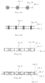
- the Fig. 2a shows a reinforcement mat 2a.0 with a grid-like textile surface structure 2a.1 and pressure bodies 2a.10.
- the pressure bodies 2a.10 are connected approximately centrally to the textile surface structure 2a.1.
- Fig. 2b shows another reinforcement mat 2b.0 with two textile fabrics 2b.1 and 2b.2. These are connected to each other by pressure bodies 2b.10.
- FIG. 2c Two textile fabrics 2c.1, 2c.2 and pressure bodies 2c.10 can be seen, which form a reinforcement mat 2c.0.
- connecting means 2c.5, in particular fiber strands, are provided for connecting, in particular lashing, the textile fabrics 2c.1 and 2c.2.
- the pressure bodies 2c.10 are clamped between the textile fabrics 2c.1, 2c.2.
- Fig. 2d Two textile fabrics 2d.1, 2d.2 and in particular tensile connecting means 2d.5 and pressure body 2d.10 are provided.
- the embodiment of the Fig. 2d a third textile fabric 2d.3.
- the third textile fabric is arranged between the other two textile fabrics 2d.1, 2d.2 and alternately extends over and under the pressure bodies 2d.10.
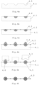
- FIG. 3a to Fig. 3e A first manufacturing process is shown schematically. Between a lower tool 3.1 and an upper tool 3.3, a Fig. 3a to Fig. 3c a textile fabric 3.2 is clamped in. According to Fig. 3d Material for the pressure bodies to be formed is then injected through openings 3.4 in recesses 3.5 of the lower and upper tools 3.1, 3.3. In this case, depending on the desired material of the pressure bodies to be produced, liquefied, e.g. thermally liquefied, plastic or self-hardening special mortar is injected. After hardening, the lower and upper tools 3.1, 3.3 can then be removed and the finished reinforcement mat 3.0 ( Fig. 3e ) can be taken.
- liquefied e.g. thermally liquefied
- plastic or self-hardening special mortar is injected. After hardening, the lower and upper tools 3.1, 3.3 can then be removed and the finished reinforcement mat 3.0 ( Fig. 3e ) can be taken
- a lower tool 4.1 has recesses 4.5 into which raw material 4.6 is poured ( Fig. 4a and Fig. 4b ).
- a textile fabric 4.2 is then placed on top ( Fig. 4c According to the positions of the recesses 4.5, Fig. 4d Additional raw material 4.6 is applied point by point.
- the additional raw material 4.6 is then finally formed ( Fig. 4e ).
- a reinforcement mat 4.0 ( Fig. 4f ) can be taken.
- FIG. 5a and Fig. 5b Monolithically formed pressure hull designs are shown in perspective and cross-sectional views.
- the pressure hull 5.10 of the Fig. 5a has a groove 5.1.
- the pressure body 5.11 of the Fig. 5b two grooves 5.1 and 5.2.
- the pressure bodies 5.10, 5.11 can thus be connected to one or two textile fabrics by means of the grooves 5.1, 5.2, in that (mesh) webs of the textile fabrics engage in the grooves 5.1, 5.2.
- grooves 5.1, 5.2 are circular. This means that the pressure bodies 5.10, 5.11 can be screwed into a textile fabric particularly easily, as will be explained in more detail later.
- the pressure hull 6.10 of the Fig. 6a has two grooves 6.1, 6.2.
- the grooves 6.1, 6.2 are polygonal in cross-section, in particular octagonal.
- the grooves 6.1, 6.2 each have recesses only in corner areas of the pressure body 6.10. This makes it easier or better to snap into and/or screw the pressure body 6.10 into a textile fabric.
- the pressure hull 6.11 of the Fig. 6b with an intermediate body 6.4 and two locking means 6.3 is designed to lock into meshes of a textile fabric that are shaped to match the locking means 6.3 or click in and thus connect with the textile surface structure.
- the intermediate body 6.4 has a relatively large cross-section.
- the intermediate body 6.4 has a cross-sectional area that is significantly larger than the cross-sectional areas of the locking means 6.3. Due to its large cross-sectional area, it is particularly suitable for absorbing loads and distributing them over a large area, in particular across several meshes of a textile fabric.
- Fig. 7a to 7c now show various textile fabrics 7.1, 7.2, 7.3, which have a square ( Fig. 7a ), a triangular ( Fig. 7b ) or a hexagonal ( Fig. 7c ) lattice structure.
- Pressure bodies 7.11, 7.12 and 7.13, each shaped according to the lattice structure can be connected to the respective textile fabrics 7.1, 7.2 and 7.3 by first inserting them into the respective textile fabric 7.1, 7.2, 7.3 and then rotating them by approximately 45°, 60° or 30°.
- the respective textile fabric 7.1, 7.2, 7.3 can be arranged at the level of suitably shaped grooves, for example in the manner of the grooves 5.1, 5.2, 6.1, 6.2.
- the pressure bodies 7.11, 7.12 and 7.13 can thus be connected to the respective textile fabric 7.1, 7.2 and 7.3 by screwing them in.
- the pressure bodies 7.11, 7.12, 7.13 are regularly distributed over the respective textile fabrics 7.1, 7.2, 7.3. They have predefined distances d 1 , d 2 , d 3 between adjacent pressure bodies 7.11, 7.12 and 7.13.
- the Fig. 8a and the Fig. 8b a multi-part pressure body 8.10.
- the pressure body 8.10 consists of three parts 8.1, 8.2, 8.3, between which textile fabrics are inserted or clamped by means of suitable recesses 8.4 to form a reinforcement mat.
- the parts 8.1, 8.2, 8.3 are each plugged together by means of plug-in receptacles or locking means (not shown in detail) and thus connected to one another.
- a textile fabric can be formed using the pressure body 8.10.
- individual fiber strands are inserted into the recesses 8.4 instead of a prefabricated textile fabric.
- the textile fabric is formed using the pressure body 8.10.
- One pressure body 8.10 is arranged at at least one node of the textile fabric or forms this node.
Landscapes
- Engineering & Computer Science (AREA)
- Architecture (AREA)
- Civil Engineering (AREA)
- Structural Engineering (AREA)
- Bridges Or Land Bridges (AREA)
- Road Paving Structures (AREA)
Claims (15)
- Treillis d'armature (2, 2a.0, 2b.0, 2c.0, 2d.0, 3.0, 4.0) pour l'armature d'une couche de pose (4) non liée dans une construction routière et de chemin comportant une structure textile plane (5, 2a.1, 2b.1, 2b.2, 2c.1, 2c.2, 2d.1, 2d.2, 3.2, 4.2, 7.1, 7.2, 7.3) en forme de filet ou de grille qui présente au moins un corps sous pression (3, 2a.10, 2b.10, 2c.10, 2d.10, 5.10, 5.11, 6.10, 6.11, 7.11, 7.12, 7.13, 8.10), dans lequel le corps sous pression (3, 2a.10, 2b.10, 2c.10, 2d.10, 5.10, 5.11, 6.10, 6.11, 7.11, 7.12, 7.13, 8.10) est conçu pour l'absorption de charge de la couche de pose (4) ou d'une couche se trouvant au-dessus de celle-ci, dans lequel l'au moins un corps sous pression est relié par adhérence à la structure textile plane, caractérisé en ce qu'au moins un corps sous pression (3, 2a.10, 2b.10, 2c.10, 2d.10, 5.10, 5.11, 6.10, 6.11, 7.11, 7.12, 7.13, 8.10) est conçu comme point de jonction de la structure textile plane (5, 2a.1, 2b.1, 2b.2, 2c.1, 2c.2, 2d.1, 2d.2, 3.2, 4.2, 7.1, 7.2, 7.3) ou est disposé sur un point de jonction de la structure textile plane (5, 2a.1, 2b.1, 2b.2, 2c.1, 2c.2, 2d.1, 2d.2, 3.2, 4.2, 7.1, 7.2, 7.3).
- Treillis d'armature selon la revendication 1, caractérisé en ce qu'au moins un corps sous pression (3, 2a.10, 2b.10, 2c.10, 2d.10, 5.10, 5.11, 6.10, 6.11, 7.11, 7.12, 7.13, 8.10) est disposé sur une entretoise entre deux points de jonction de la structure textile plane (5, 2a.1, 2b.1, 2b.2, 2c.1, 2c.2, 2d.1, 2d.2, 3.2, 4.2, 7.1, 7.2, 7.3).
- Treillis d'armature selon la revendication 1 ou 2, caractérisé en ce que le corps sous pression (3, 2a.10, 2b.10, 2c.10, 2d.10, 5.10, 5.11, 6.10, 6.11, 7.11, 7.12, 7.13, 8.10) présente une résistance à la compression d'au moins 1 MN/m2, de préférence d'au moins 10 MN/m2, et/ou au moins une résistance à la compression correspondant au matériau de la couche de pose (4).
- Treillis d'armature selon l'une des revendications précédentes,
caractérisé en ce que la hauteur du corps sous pression (3, 2a.10, 2b.10, 2c.10, 2d.10, 5.10, 5.11, 6.10, 6.11, 7.11, 7.12, 7.13, 8.10) est au moins le triple, de préférence le décuple, de la hauteur de la structure textile plane (5, 2a.1, 2b.1, 2b.2, 2c.1, 2c.2, 2d.1, 2d.2, 3.2, 4.2, 7.1, 7.2, 7.3). - Treillis d'armature selon l'une des revendications précédentes,
caractérisé en ce que le corps sous pression (3, 2a.10, 2b.10, 2c.10, 2d.10, 5.10, 5.11, 6.10, 6.11, 7.11, 7.12, 7.13, 8.10) est formé de pierre, béton, asphalte, matière plastique et/ou acier. - Treillis d'armature selon l'une des revendications précédentes,
caractérisé en ce que le corps sous pression (3, 2a.10, 2b.10, 2c.10, 2d.10, 5.10, 5.11, 6.10, 6.11, 7.11, 7.12, 7.13, 8.10) est conçu massif et/ou compact. - Treillis d'armature selon l'une des revendications précédentes,
caractérisé en ce que le corps sous pression (3, 2a.10, 2b.10, 2c.10, 2d.10, 5.10, 5.11, 6.10, 6.11, 7.11, 7.12, 7.13, 8.10) présente une résistance à la traction qui correspond au moins à la résistance à la traction de la structure textile plane (5, 2a.1, 2b.1, 2b.2, 2c.1, 2c.2, 2d.1, 2d.2, 3.2, 4.2, 7.1, 7.2, 7.3). - Treillis d'armature selon l'une des revendications précédentes,
caractérisé en ce que le treillis d'armature (2, 2a.0, 2b.0, 2c.0, 2d.0, 3.0, 4.0) présente plusieurs corps sous pression (3, 2a.10, 2b.10, 2c.10, 2d.10, 5.10, 5.11, 6.10, 6.11, 7.11, 7.12, 7.13, 8.10), dans lequel les corps sous pression (3, 2a.10, 2b.10, 2c.10, 2d.10, 5.10, 5.11, 6.10, 6.11, 7.11, 7.12, 7.13, 8.10) sont de préférence disposés régulièrement et/ou à des distances prédéfinies (d1, d2, d3) les uns des autres. - Treillis d'armature selon l'une des revendications précédentes,
caractérisé en ce que le corps sous pression (3, 2a.10, 2b.10, 2c.10, 2d.10, 5.10, 5.11, 6.10, 6.11, 7.11, 7.12, 7.13, 8.10) est relié par complémentarité de forme à la structure textile plane (5, 2a.1, 2b.1, 2b.2, 2c.1, 2c.2, 2d.1, 2d.2, 3.2, 4.2, 7.1, 7.2, 7.3), de préférence est enfiché, enfilé, pressé, cousu, coulé, tourné, accroché dans la structure textile plane (5, 2a.1, 2b.1, 2b.2, 2c.1, 2c.2, 2d.1, 2d.2, 3.2, 4.2, 7.1, 7.2, 7.3) et/ou relié à celle-ci par vissage. - Treillis d'armature selon l'une des revendications précédentes,
caractérisé en ce que le treillis d'armature (2, 2a.0, 2b.0, 2c.0, 2d.0, 3.0, 4.0) présente une deuxième structure textile plane (5, 2a.1, 2b.1, 2b.2, 2c.1, 2c.2, 2d.1, 2d.2, 3.2, 4.2, 7.1, 7.2, 7.3) qui, de préférence à l'aide du corps sous pression (3, 2a.10, 2b.10, 2c.10, 2d.10, 5.10, 5.11, 6.10, 6.11, 7.11, 7.12, 7.13, 8.10), est reliée à la structure textile plane (5, 2a.1, 2b.1, 2b.2, 2c.1, 2c.2, 2d.1, 2d.2, 3.2, 4.2, 7.1, 7.2, 7.3), de préférence est enfichée, enfilée, pressée, cousue, coulée, tournée, accrochée dans le corps sous pression (3, 2a.10, 2b.10, 2c.10, 2d.10, 5.10, 5.11, 6.10, 6.11, 7.11, 7.12, 7.13, 8.10) et/ou reliée à celui-ci par vissage. - Treillis d'armature selon l'une des revendications précédentes,
caractérisé en ce que le treillis d'armature (2, 2a.0, 2b.0, 2c.0, 2d.0, 3.0, 4.0) présente une troisième structure textile plane (5, 2a.1, 2b.1, 2b.2, 2c.1, 2c.2, 2d.1, 2d.2, 3.2, 4.2, 7.1, 7.2, 7.3) qui, de préférence à l'aide du corps sous pression (3, 2a.10, 2b.10, 2c.10, 2d.10, 5.10, 5.11, 6.10, 6.11, 7.11, 7.12, 7.13, 8.10), est reliée aux deux autres structures textiles planes (5, 2a.1, 2b.1, 2b.2, 2c.1, 2c.2, 2d.1, 2d.2, 3.2, 4.2, 7.1, 7.2, 7.3). - Treillis d'armature selon l'une des revendications précédentes,
caractérisé en ce qu'au moins deux structures textiles planes (5, 2a.1, 2b.1, 2b.2, 2c.1, 2c.2, 2d.1, 2d.2, 3.2, 4.2, 7.1, 7.2, 7.3) sont reliées entre elles par un moyen de liaison (2c.5, 2d.5). - Treillis d'armature selon l'une des revendications précédentes,
caractérisé en ce que le treillis d'armature présente une couche adhésive et/ou une couche de fusion. - Ensemble routier (1) comportant un treillis d'armature (2, 2a.0, 2b.0, 2c.0, 2d.0, 3.0, 4.0) selon l'une des revendications précédentes et au moins une couche de pose (4).
- Ensemble routier selon la revendication 14, caractérisé en ce que la couche de pose (4) du treillis d'armature (2, 2a.0, 2b.0, 2c.0, 2d.0, 3.0, 4.0) est constituée d'asphalte roulé.
Applications Claiming Priority (1)
| Application Number | Priority Date | Filing Date | Title |
|---|---|---|---|
| DE102016114821.0A DE102016114821A1 (de) | 2016-08-10 | 2016-08-10 | Bewehrungsmatte mit Druckkörpern sowie Straßenaufbau |
Publications (3)
| Publication Number | Publication Date |
|---|---|
| EP3282063A1 EP3282063A1 (fr) | 2018-02-14 |
| EP3282063B1 true EP3282063B1 (fr) | 2024-10-02 |
| EP3282063C0 EP3282063C0 (fr) | 2024-10-02 |
Family
ID=59581757
Family Applications (1)
| Application Number | Title | Priority Date | Filing Date |
|---|---|---|---|
| EP17185529.9A Active EP3282063B1 (fr) | 2016-08-10 | 2017-08-09 | Treillis métallique pourvu de corps de pression ainsi que structure de chaussée |
Country Status (2)
| Country | Link |
|---|---|
| EP (1) | EP3282063B1 (fr) |
| DE (1) | DE102016114821A1 (fr) |
Family Cites Families (7)
| Publication number | Priority date | Publication date | Assignee | Title |
|---|---|---|---|---|
| FR336803A (fr) * | 1903-01-28 | 1904-03-18 | Edmond Uhry | Nouveaux revetements en asphalte boisé pour rues, chaussées, etc. |
| NL7904906A (nl) * | 1979-06-22 | 1980-12-24 | Harm Last Gerrit Eenkhoorn Ger | Werkwijze voor het vervaardigen van een bodembekleding, de bodembekleding en het halfprodukt daarvoor. |
| GB2390565A (en) | 2002-06-27 | 2004-01-14 | Tensar Internat Ltd | Geogrid |
| JP5419155B2 (ja) * | 2009-11-19 | 2014-02-19 | 独立行政法人国立高等専門学校機構 | アスファルト舗装方法 |
| DE102012004785A1 (de) * | 2012-03-06 | 2013-09-12 | beweka Betonwerk Kahla GmbH | Abstandhalter zum Einsetzen in mit einem Basismaterialherzustellende Bauteile mit integrierten textilen Strukturen |
| NO2975327T3 (fr) * | 2013-09-18 | 2018-03-10 | ||
| EP2940230A1 (fr) * | 2014-04-30 | 2015-11-04 | Sika Technology AG | Tissu en 3D pour constructions de plancher flottant |
-
2016
- 2016-08-10 DE DE102016114821.0A patent/DE102016114821A1/de not_active Ceased
-
2017
- 2017-08-09 EP EP17185529.9A patent/EP3282063B1/fr active Active
Also Published As
| Publication number | Publication date |
|---|---|
| EP3282063A1 (fr) | 2018-02-14 |
| DE102016114821A1 (de) | 2018-02-15 |
| EP3282063C0 (fr) | 2024-10-02 |
Similar Documents
| Publication | Publication Date | Title |
|---|---|---|
| EP3706972B1 (fr) | Procédé de fabrication d'un élément de construction et élément de construction correspondant | |
| EP1146180B1 (fr) | Procédé pour la fabrication d'un élément de plancher en béton et élément de plancher en béton | |
| WO2019092169A1 (fr) | Armature de corps en béton imprimés en 3d | |
| WO2005080704A1 (fr) | Procede et agent auxiliaire pour produire des elements en beton, en particulier des produits semi-finis en beton et/ou des revetements en beton, et agent auxiliaire pour produire des revetements en beton | |
| DE102018109501A1 (de) | Bewehrung von 3D-gedruckten Betonkörpern | |
| WO1991005111A1 (fr) | Piece moulee en beton forme de plaque et procede et dispositif de fabrication | |
| WO2019092162A1 (fr) | Armature de corps en béton imprimés en 3d | |
| EP0051101B1 (fr) | Plaque en ciment et procédé et dispositif pour sa fabrication | |
| EP0495334A1 (fr) | Armature de cisaillement pour des plafonds plats | |
| EP2209952B1 (fr) | Élément d'écartement et composant pour la production d'une structure murale, et procédé et dispositif correspondants | |
| DE19805571C2 (de) | Betonbauelement | |
| EP3282063B1 (fr) | Treillis métallique pourvu de corps de pression ainsi que structure de chaussée | |
| DE69403349T2 (de) | Blockmatratze zum Schutz von Hängen, Böschungen und dergleichen | |
| DE102004060822A1 (de) | Rasengitterstein | |
| DE1812865C3 (de) | Bewehrung fur flächige Betonbauteile | |
| EP2783045B1 (fr) | Pavé en pierre artificielle et procédé de fabrication dudit pavé | |
| EP4015708B1 (fr) | Bloc de béton destiné à la fabrication d'un revêtement de surface, revêtement de surface, ainsi que procédé de fabrication d'un bloc de béton | |
| DE4110827C2 (de) | Plattenmaterial für Bauzwecke sowie Verfahren zu dessen Herstellung | |
| DE102018130843A1 (de) | Vorrichtung zur Wärmeentkopplung zwischen einer betonierten Gebäudewand und einer Geschossdecke sowie Herstellverfahren | |
| DE202017106103U1 (de) | Drahtkorb und Schutzwand gegen Lärm und/oder Hochwasser | |
| DE102023004452A1 (de) | Betonpflasterstein | |
| DE202006015918U1 (de) | Abstandhaltereinrichtung | |
| DE9411147U1 (de) | Pflasterstein, insbesondere für Schwerlastverkehr | |
| AT284188B (de) | Formstein zur Herstellung einer Fahrbahn-, Platz- oder Wegebefestigung | |
| WO2012126026A2 (fr) | Dispositif pour réaliser un joint de dilatation |
Legal Events
| Date | Code | Title | Description |
|---|---|---|---|
| PUAI | Public reference made under article 153(3) epc to a published international application that has entered the european phase |
Free format text: ORIGINAL CODE: 0009012 |
|
| STAA | Information on the status of an ep patent application or granted ep patent |
Free format text: STATUS: THE APPLICATION HAS BEEN PUBLISHED |
|
| AK | Designated contracting states |
Kind code of ref document: A1 Designated state(s): AL AT BE BG CH CY CZ DE DK EE ES FI FR GB GR HR HU IE IS IT LI LT LU LV MC MK MT NL NO PL PT RO RS SE SI SK SM TR |
|
| AX | Request for extension of the european patent |
Extension state: BA ME |
|
| STAA | Information on the status of an ep patent application or granted ep patent |
Free format text: STATUS: REQUEST FOR EXAMINATION WAS MADE |
|
| 17P | Request for examination filed |
Effective date: 20180223 |
|
| RBV | Designated contracting states (corrected) |
Designated state(s): AL AT BE BG CH CY CZ DE DK EE ES FI FR GB GR HR HU IE IS IT LI LT LU LV MC MK MT NL NO PL PT RO RS SE SI SK SM TR |
|
| STAA | Information on the status of an ep patent application or granted ep patent |
Free format text: STATUS: EXAMINATION IS IN PROGRESS |
|
| 17Q | First examination report despatched |
Effective date: 20190225 |
|
| RAP1 | Party data changed (applicant data changed or rights of an application transferred) |
Owner name: RIEKERT, JUERGEN |
|
| RIN1 | Information on inventor provided before grant (corrected) |
Inventor name: RIEKERT, JUERGEN |
|
| GRAP | Despatch of communication of intention to grant a patent |
Free format text: ORIGINAL CODE: EPIDOSNIGR1 |
|
| STAA | Information on the status of an ep patent application or granted ep patent |
Free format text: STATUS: GRANT OF PATENT IS INTENDED |
|
| INTG | Intention to grant announced |
Effective date: 20240422 |
|
| GRAS | Grant fee paid |
Free format text: ORIGINAL CODE: EPIDOSNIGR3 |
|
| GRAA | (expected) grant |
Free format text: ORIGINAL CODE: 0009210 |
|
| STAA | Information on the status of an ep patent application or granted ep patent |
Free format text: STATUS: THE PATENT HAS BEEN GRANTED |
|
| AK | Designated contracting states |
Kind code of ref document: B1 Designated state(s): AL AT BE BG CH CY CZ DE DK EE ES FI FR GB GR HR HU IE IS IT LI LT LU LV MC MK MT NL NO PL PT RO RS SE SI SK SM TR |
|
| REG | Reference to a national code |
Ref country code: GB Ref legal event code: FG4D Free format text: NOT ENGLISH |
|
| REG | Reference to a national code |
Ref country code: CH Ref legal event code: EP |
|
| REG | Reference to a national code |
Ref country code: IE Ref legal event code: FG4D Free format text: LANGUAGE OF EP DOCUMENT: GERMAN |
|
| REG | Reference to a national code |
Ref country code: DE Ref legal event code: R096 Ref document number: 502017016458 Country of ref document: DE |
|
| U01 | Request for unitary effect filed |
Effective date: 20241028 |
|
| U07 | Unitary effect registered |
Designated state(s): AT BE BG DE DK EE FI FR IT LT LU LV MT NL PT RO SE SI Effective date: 20241107 |
|
| PG25 | Lapsed in a contracting state [announced via postgrant information from national office to epo] |
Ref country code: HR Free format text: LAPSE BECAUSE OF FAILURE TO SUBMIT A TRANSLATION OF THE DESCRIPTION OR TO PAY THE FEE WITHIN THE PRESCRIBED TIME-LIMIT Effective date: 20241002 Ref country code: IS Free format text: LAPSE BECAUSE OF FAILURE TO SUBMIT A TRANSLATION OF THE DESCRIPTION OR TO PAY THE FEE WITHIN THE PRESCRIBED TIME-LIMIT Effective date: 20250202 |
|
| PG25 | Lapsed in a contracting state [announced via postgrant information from national office to epo] |
Ref country code: ES Free format text: LAPSE BECAUSE OF FAILURE TO SUBMIT A TRANSLATION OF THE DESCRIPTION OR TO PAY THE FEE WITHIN THE PRESCRIBED TIME-LIMIT Effective date: 20241002 |
|
| PG25 | Lapsed in a contracting state [announced via postgrant information from national office to epo] |
Ref country code: NO Free format text: LAPSE BECAUSE OF FAILURE TO SUBMIT A TRANSLATION OF THE DESCRIPTION OR TO PAY THE FEE WITHIN THE PRESCRIBED TIME-LIMIT Effective date: 20250102 |
|
| PG25 | Lapsed in a contracting state [announced via postgrant information from national office to epo] |
Ref country code: GR Free format text: LAPSE BECAUSE OF FAILURE TO SUBMIT A TRANSLATION OF THE DESCRIPTION OR TO PAY THE FEE WITHIN THE PRESCRIBED TIME-LIMIT Effective date: 20250103 |
|
| PG25 | Lapsed in a contracting state [announced via postgrant information from national office to epo] |
Ref country code: PL Free format text: LAPSE BECAUSE OF FAILURE TO SUBMIT A TRANSLATION OF THE DESCRIPTION OR TO PAY THE FEE WITHIN THE PRESCRIBED TIME-LIMIT Effective date: 20241002 Ref country code: CZ Free format text: LAPSE BECAUSE OF FAILURE TO SUBMIT A TRANSLATION OF THE DESCRIPTION OR TO PAY THE FEE WITHIN THE PRESCRIBED TIME-LIMIT Effective date: 20241002 |
|
| PG25 | Lapsed in a contracting state [announced via postgrant information from national office to epo] |
Ref country code: RS Free format text: LAPSE BECAUSE OF FAILURE TO SUBMIT A TRANSLATION OF THE DESCRIPTION OR TO PAY THE FEE WITHIN THE PRESCRIBED TIME-LIMIT Effective date: 20250102 |
|
| PG25 | Lapsed in a contracting state [announced via postgrant information from national office to epo] |
Ref country code: SM Free format text: LAPSE BECAUSE OF FAILURE TO SUBMIT A TRANSLATION OF THE DESCRIPTION OR TO PAY THE FEE WITHIN THE PRESCRIBED TIME-LIMIT Effective date: 20241002 |
|
| PG25 | Lapsed in a contracting state [announced via postgrant information from national office to epo] |
Ref country code: SK Free format text: LAPSE BECAUSE OF FAILURE TO SUBMIT A TRANSLATION OF THE DESCRIPTION OR TO PAY THE FEE WITHIN THE PRESCRIBED TIME-LIMIT Effective date: 20241002 |
|
| PLBE | No opposition filed within time limit |
Free format text: ORIGINAL CODE: 0009261 |
|
| STAA | Information on the status of an ep patent application or granted ep patent |
Free format text: STATUS: NO OPPOSITION FILED WITHIN TIME LIMIT |
|
| 26N | No opposition filed |
Effective date: 20250703 |
|
| U20 | Renewal fee for the european patent with unitary effect paid |
Year of fee payment: 9 Effective date: 20250825 |
|
| REG | Reference to a national code |
Ref country code: CH Ref legal event code: H13 Free format text: ST27 STATUS EVENT CODE: U-0-0-H10-H13 (AS PROVIDED BY THE NATIONAL OFFICE) Effective date: 20260324 |
|
| PG25 | Lapsed in a contracting state [announced via postgrant information from national office to epo] |
Ref country code: MC Free format text: LAPSE BECAUSE OF FAILURE TO SUBMIT A TRANSLATION OF THE DESCRIPTION OR TO PAY THE FEE WITHIN THE PRESCRIBED TIME-LIMIT Effective date: 20241002 |
|
| PG25 | Lapsed in a contracting state [announced via postgrant information from national office to epo] |
Ref country code: CH Free format text: LAPSE BECAUSE OF NON-PAYMENT OF DUE FEES Effective date: 20250831 |