EP3282129A1 - Vakuumsystem - Google Patents
Vakuumsystem Download PDFInfo
- Publication number
- EP3282129A1 EP3282129A1 EP16202522.5A EP16202522A EP3282129A1 EP 3282129 A1 EP3282129 A1 EP 3282129A1 EP 16202522 A EP16202522 A EP 16202522A EP 3282129 A1 EP3282129 A1 EP 3282129A1
- Authority
- EP
- European Patent Office
- Prior art keywords
- vacuum
- vacuum pump
- pressure
- inlet
- rotor
- Prior art date
- Legal status (The legal status is an assumption and is not a legal conclusion. Google has not performed a legal analysis and makes no representation as to the accuracy of the status listed.)
- Granted
Links
Images



Classifications
-
- F—MECHANICAL ENGINEERING; LIGHTING; HEATING; WEAPONS; BLASTING
- F04—POSITIVE - DISPLACEMENT MACHINES FOR LIQUIDS; PUMPS FOR LIQUIDS OR ELASTIC FLUIDS
- F04D—NON-POSITIVE-DISPLACEMENT PUMPS
- F04D19/00—Axial-flow pumps
- F04D19/02—Multi-stage pumps
- F04D19/04—Multi-stage pumps specially adapted to the production of a high vacuum, e.g. molecular pumps
-
- F—MECHANICAL ENGINEERING; LIGHTING; HEATING; WEAPONS; BLASTING
- F04—POSITIVE - DISPLACEMENT MACHINES FOR LIQUIDS; PUMPS FOR LIQUIDS OR ELASTIC FLUIDS
- F04D—NON-POSITIVE-DISPLACEMENT PUMPS
- F04D27/00—Control, e.g. regulation, of pumps, pumping installations or pumping systems specially adapted for elastic fluids
- F04D27/02—Surge control
- F04D27/0253—Surge control by throttling
-
- F—MECHANICAL ENGINEERING; LIGHTING; HEATING; WEAPONS; BLASTING
- F04—POSITIVE - DISPLACEMENT MACHINES FOR LIQUIDS; PUMPS FOR LIQUIDS OR ELASTIC FLUIDS
- F04D—NON-POSITIVE-DISPLACEMENT PUMPS
- F04D29/00—Details, component parts, or accessories
- F04D29/40—Casings; Connections of working fluid
- F04D29/52—Casings; Connections of working fluid for axial pumps
- F04D29/522—Casings; Connections of working fluid for axial pumps especially adapted for elastic fluid pumps
- F04D29/524—Casings; Connections of working fluid for axial pumps especially adapted for elastic fluid pumps shiftable members for obturating part of the flow path
-
- F—MECHANICAL ENGINEERING; LIGHTING; HEATING; WEAPONS; BLASTING
- F04—POSITIVE - DISPLACEMENT MACHINES FOR LIQUIDS; PUMPS FOR LIQUIDS OR ELASTIC FLUIDS
- F04D—NON-POSITIVE-DISPLACEMENT PUMPS
- F04D29/00—Details, component parts, or accessories
- F04D29/40—Casings; Connections of working fluid
- F04D29/52—Casings; Connections of working fluid for axial pumps
- F04D29/522—Casings; Connections of working fluid for axial pumps especially adapted for elastic fluid pumps
- F04D29/526—Details of the casing section radially opposing blade tips
-
- F—MECHANICAL ENGINEERING; LIGHTING; HEATING; WEAPONS; BLASTING
- F04—POSITIVE - DISPLACEMENT MACHINES FOR LIQUIDS; PUMPS FOR LIQUIDS OR ELASTIC FLUIDS
- F04D—NON-POSITIVE-DISPLACEMENT PUMPS
- F04D29/00—Details, component parts, or accessories
- F04D29/70—Suction grids; Strainers; Dust separation; Cleaning
- F04D29/701—Suction grids; Strainers; Dust separation; Cleaning especially adapted for elastic fluid pumps
-
- G—PHYSICS
- G01—MEASURING; TESTING
- G01M—TESTING STATIC OR DYNAMIC BALANCE OF MACHINES OR STRUCTURES; TESTING OF STRUCTURES OR APPARATUS, NOT OTHERWISE PROVIDED FOR
- G01M3/00—Investigating fluid-tightness of structures
- G01M3/02—Investigating fluid-tightness of structures by using fluid or vacuum
- G01M3/04—Investigating fluid-tightness of structures by using fluid or vacuum by detecting the presence of fluid at the leakage point
- G01M3/20—Investigating fluid-tightness of structures by using fluid or vacuum by detecting the presence of fluid at the leakage point using special tracer materials, e.g. dye, fluorescent material, radioactive material
- G01M3/202—Investigating fluid-tightness of structures by using fluid or vacuum by detecting the presence of fluid at the leakage point using special tracer materials, e.g. dye, fluorescent material, radioactive material using mass spectrometer detection systems
- G01M3/205—Accessories or associated equipment; Pump constructions
-
- F—MECHANICAL ENGINEERING; LIGHTING; HEATING; WEAPONS; BLASTING
- F04—POSITIVE - DISPLACEMENT MACHINES FOR LIQUIDS; PUMPS FOR LIQUIDS OR ELASTIC FLUIDS
- F04D—NON-POSITIVE-DISPLACEMENT PUMPS
- F04D29/00—Details, component parts, or accessories
- F04D29/60—Mounting; Assembling; Disassembling
- F04D29/64—Mounting; Assembling; Disassembling of axial pumps
- F04D29/644—Mounting; Assembling; Disassembling of axial pumps especially adapted for elastic fluid pumps
-
- F—MECHANICAL ENGINEERING; LIGHTING; HEATING; WEAPONS; BLASTING
- F05—INDEXING SCHEMES RELATING TO ENGINES OR PUMPS IN VARIOUS SUBCLASSES OF CLASSES F01-F04
- F05D—INDEXING SCHEME FOR ASPECTS RELATING TO NON-POSITIVE-DISPLACEMENT MACHINES OR ENGINES, GAS-TURBINES OR JET-PROPULSION PLANTS
- F05D2270/00—Control
- F05D2270/30—Control parameters, e.g. input parameters
- F05D2270/301—Pressure
- F05D2270/3013—Outlet pressure
Definitions
- the present invention relates to a vacuum system, in particular vacuum pump or arrangement of at least one vacuum device, preferably a vacuum pump, and at least one recipient, preferably a vacuum chamber or a measuring device such. an electron microscope. Furthermore, the invention relates to methods for operating a vacuum system, in particular a vacuum system as described herein.
- the invention relates to a turbomolecular vacuum pump, in particular a split-flow pump, having a housing which has at least one inlet for connecting the pump to a recipient, and a rotor which is arranged in the housing and rotates about a rotor axis during operation Rotor has a plurality of circumferentially spaced rotor blades.
- vacuum devices are intended to have at least one enclosed interior or other devices connected to other devices whose absolute pressure is below an ambient pressure, for example an atmospheric pressure, of the device environment.
- a device may also be arranged within a complete system in a vacuum space and inside, for example, have devices which are operated at a pressure level other than that of the vacuum space, both lower, equal or higher than the ambient atmospheric pressure of the entire system.
- a vacuum system comprises a working area, a separating element and a control space, which is separated from the working area by the separating element and in which there is a control pressure variable relative to the pressure in the working area.
- the vacuum system according to the invention which can be in particular a vacuum pump, allows a particularly compact design, a simple construction and, in particular with the above advantages, low production costs, in particular over a use of a conventional, for example electromagnetically operated actuator, e.g. Actuator or solenoid.
- a conventional, for example electromagnetically operated actuator e.g. Actuator or solenoid.
- the working movement can be achieved according to the invention at least in the vicinity of the working area without generating electric fields or magnetic fields.
- any electro-magnetically sensitive elements present in the working area such as e.g. Electron microscopes, not negatively affected.
- control pressure leads to a low power consumption for effecting the working movement and thus contributes to a good energy efficiency of the vacuum system and to a low heat generation in the work area.
- the work area is a vacuum area.
- the vacuum region may have a pressure which is lower than an ambient pressure of the vacuum system.
- only the separating element can perform the working movement.
- a working device such as a slide, lever or switch act on, in particular mechanically, pneumatically, hydraulically, electrically and / or magnetically.
- the loading need not result in a working movement in addition to that of the separating means, i. the working equipment involved does not have to move itself.
- an electrically conductive separating member can establish an electrical contact between two areas of a stationary working device.
- the working device comprises a closure, a flap, a valve, a valve component, a rolling or magnetic bearing or a component of a rolling or magnetic bearing.
- the working area may comprise at least one flow path, in particular a fluid channel, for a working or operating fluid, wherein the fluid flow along the flow path can be influenced by the working movement.
- the working fluid may be or include any gas or liquid.
- the working fluid may be or include air.
- the operating fluid may be or include, for example, oil, eg lubricating oil.
- a flow cross-section of the flow path can be changed at least one work site by the working movement.
- the separating element can be arranged, for example, outside the working area.
- the working movement may include a movement of the separating member into the working area.
- the working movement affects the work area, in particular only passively.
- the term "passive" in the context of the present invention may mean that the influence is essentially free of power transmission to a working medium in the working area and / or energy-neutral with respect to the working medium.
- passive influencing can cause a working medium to be impeded only more or less with respect to a flow of the working medium.
- a cross-sectional change of a fluid channel located in the working area can be effected in order to passively influence the working area.
- the working movement in the work area triggers an actuation process or carries it out itself.
- the separating member can be operated as a switch, in particular as a bistable switch.
- the separating member is movable by changing the control pressure between at least two switching positions. Furthermore, the separating member may also be continuously movable or actuated.
- the separating member may also be controllable to a linear movement or to a movement with a non-linear motion profile.
- the separating member has a reset function.
- the separating element can always be kept in a defined state as a function of a pressure in the control chamber by the reset function.
- a restoring device e.g. Spring, be provided.
- the separating member can be reset by reversing the control pressure.
- a connection between the control room and the work area is provided, which communicates a pressure prevailing in the work area to the control room.
- the pressure may be a pressure prevailing in the work area when the vacuum system is in operation, e.g. during operation of a vacuum pump.
- a pressure in the work area is different from an ambient pressure, in particular smaller than an ambient pressure.
- connection communicates a pressure prevailing at the outlet of a vacuum pump to the control chamber.
- the connection can be controllable, for example, with respect to a permeability or a conductance.
- a backing pump is provided to generate a pre-vacuum at the outlet of the vacuum pump, and the connection communicates a fore-vacuum pressure to the control chamber.
- a first connection to a first region with a first pressure and a second connection to a second region with a second pressure are provided for the control chamber, wherein at least one, in particular both, of the compounds with respect to a Permeability or conductance is controllable.
- the compounds may also be connected by a common control means, e.g. a switching valve, be controllable.
- one or a throttle common to the connections is provided for throttling the communication of the respective pressure to the control room.
- the throttle may also be controllable with respect to their throttle effect.
- a switching device may be provided by means of which either a first pressure or a second pressure different from the first pressure can be communicated to the control chamber.
- the first or the second pressure may be a pressure prevailing at an outlet of a vacuum pump.
- the first or the second pressure may be an ambient pressure.
- a controllable connection to an ambient pressure is provided for the control room.
- the separating member may be formed, for example, as a membrane or comprise a membrane.
- the separating element may for example also be a rolling membrane and / or metallic membrane and / or be flexible, planar, pocket-shaped, bellows-like and / or single-layer or multi-layered.
- a valve may be provided, which is arranged in a fluid channel and controllable by a separating member designed as a membrane.
- the separating member may alternatively or additionally for controlling the fluid flow in the fluid channel move a valve element.
- the separating member for controlling the fluid flow itself can change a cross section of a fluid channel.
- An end position information can for example be processed and / or used by a control device of the vacuum system.
- a vacuum system in particular a vacuum pump or arrangement, comprises at least one vacuum device, preferably a vacuum pump, and at least one recipient, preferably a vacuum chamber or a measuring device, such as e.g. an electron microscope, in particular according to one of the preceding claims, at least one flow path for a working or operating fluid, and a device which is adapted to influence the fluid flow along the flow path on at least a portion of the flow path.
- the device comprises at least one actuator, which can be controlled to influence the fluid flow to an adjusting movement.
- the device is designed to change a flow cross-section of the flow path at the section.
- the device is designed to change a conductance of the flow path at the section.
- the conductance can be changed by a separating element itself or by an element moved by a separating element.
- the conductance can also be changed, for example, by actuating a valve.
- the valve may be located in the section and optionally at least partially open or close the section.
- the valve may be pressure-controlled, in particular by a pressure at the outlet of a vacuum pump.
- the vacuum system is or comprises a vacuum pump, the vacuum pump having at least one inlet for introducing working fluid to be pumped from a recipient and an outlet for ejecting the working fluid to be conveyed, the flow path being defined between inlet and outlet of the vacuum pump.
- the section may be arranged at an inlet of a vacuum pump or form the inlet.
- the portion may be disposed on at least one of a plurality of inlets of a vacuum pump.
- the vacuum pump may be a so-called split-flow vacuum pump. This type of vacuum pump is known in the art, so it need not be discussed further here.
- the one of several inlets between two Pumping stages of the vacuum pump open into a main flow path.
- the pumping stages can each be designed, for example, as a turbo, Holweck, Siegbahn, Gaede or non-molecular pumping stage or combinations thereof.
- At least one performance parameter of the vacuum pump can be adjustable for the respective inlet, in particular substantially independently of further inlets.
- different pressure levels may be set in a recipient connected to the respective inlet.
- a designed vacuum system can be particularly flexible and operate as required under many different operating scenarios.
- the device is designed to change an open cross-section in the section of the flow path in its size in order to influence the fluid flow.
- the size of the open cross section may be adjustable to at least two different values.
- the size of the open cross section may also be at least substantially infinitely adjustable.
- the device comprises a separating member and a control chamber according to an embodiment described in the first aspect of the invention, wherein the portion of the flow path corresponds to the working area or is part of the working area and the fluid flow at the portion can be influenced by the working movement.
- different fluid flows can be controlled essentially independently of one another.
- at different sections of, in particular different, flow paths at least one respective conductance value can be set at least substantially independently of other sections.
- the vacuum system can be operated very flexibly and adapted to a wide variety of operating scenarios.
- a vacuum system when starting a vacuum system can be specifically adjustable, which recipient experiences which pumping power, that is, for example, which recipient is pumped out more or faster.
- a pressure at a section, inlet and / or recipient may be controllable by the influencing according to the invention.
- a fluid permeability or a conductance of the section may be adjustable stepwise or continuously, in particular as a function of operating conditions or parameters of the vacuum system, such as, for example, a pressure, in particular a backing pressure.
- a flood resistance for a particular recipient in particular individually adjustable.
- the influencing according to the invention can be controlled, for example, by an electronic control.
- a combination of a mechanical control and an electronic control is possible.
- the device which influences the fluid flow may comprise, for example, a valve, in particular a movable protective grid, an arrangement with movable lamellae, an iris and / or a plurality and / or combination of said elements, the elements being movable in particular relative to one another could be.
- a valve in particular a movable protective grid, an arrangement with movable lamellae, an iris and / or a plurality and / or combination of said elements, the elements being movable in particular relative to one another could be.
- two protective gratings arranged one behind the other in the flow direction can be displaced transversely to the flow direction relative to one another, so that the permeability or conductance of the respective section can be adjusted.
- the device may be arranged and / or formed in the region of an inlet of a vacuum pump, in particular as an obstacle, which is arranged and / or configured such that a rotor part, in particular a rotor blade or a rotor blade, which is released in the event of a fault Fragment of a rotor blade, prevented or impeded from escaping from the inlet.
- the influencing device may for example be part of a vacuum pump or else part of an additional element.
- the device can be arranged at an inlet of a vacuum pump and, for example, be designed either as a separate element of the vacuum pump or by an additional element, such as an attachable to an inlet flange element, such as a conduit element.
- an additional element as an influencer or as part of providing retrofitting to an existing vacuum system.
- the section of the flow path can also be, for example, a bypass of the vacuum system.
- the highest possible pumping speed at a recipient of a vacuum pump may be required, for example in order to reduce an initial evacuation time for the recipient in question.
- a defined pressure may be needed, with a pumping capacity determining a necessary gas load to be admitted.
- the gas load continues to affect the energy consumption and waste heat of the vacuum pump. By reducing the pumping speed, the gas load can be reduced and thus energy consumption and waste heat can be reduced.
- a method for operating a vacuum system is presented.
- the vacuum system may in particular be a vacuum pump or arrangement of at least one vacuum device, preferably a vacuum pump, and at least one recipient, preferably a vacuum chamber or a measuring device such as a vacuum pump. an electron microscope.
- it may be a vacuum system according to one or a combination of embodiments of vacuum systems described herein.
- a fluid flow of working or operating fluid along a flow path is influenced as a function of a pressure prevailing in the vacuum system, in particular in a vacuum region.
- a fourth aspect of the invention relates to a method of operating a vacuum system comprising a vacuum pump, wherein the vacuum pump comprises at least two inlets and at least one outlet and respective, at least, between a respective inlet and the or each outlet partially different flow paths are defined, and wherein a fluid flow in at least one flow path, in particular individually, is influenced.
- the vacuum pump may be a vacuum system or a vacuum pump according to one or a combination of embodiments of vacuum systems and vacuum pumps described herein.
- the object is achieved by a turbomolecular pump, which is characterized in particular in that in the region of the inlet at least one obstacle is provided, which is arranged and / or formed such that a dissolved in a fault rotor part, in particular a Rotor blade or a fragment of a rotor blade, prevented or impeded to exit from the inlet.
- Delicate objects in the sphere of influence of the turbomolecular pump are thus protected from dissolved and, in particular, high-speed flying rotor parts.
- the inhibiting means it can not be completely ruled out by the inhibiting means that the rotor part reaches and damages the sensitive object in the area of influence of the turbo pump, at least the probability for this is reduced by the inhibiting means and / or the speed of the rotor parts is reduced, so that altogether a higher one Safety is ensured for the sensitive objects and thus the reliability of the pump according to the invention is increased.
- the sphere of influence of the turbomolecular vacuum pump may include, for example, a recipient connected to the inlet.
- the sensitive objects may include, for example, sensitive devices located in the recipient.
- the obstruction means is disposed in an expected trajectory of a disengaged rotor portion as its first obstruction and configured to deflect the rotor portion away from the inlet.
- the inhibiting means may be designed to take kinetic energy to the rotor part by collision.
- the inhibiting means may be formed, for example, as a projection or edge, in particular as a catching edge.
- the inhibiting means may be arranged on an inner surface of the housing.
- the inhibiting agent may e.g. be elongated.
- the obstacle extends along an inner surface of the housing around the rotor axis.
- the obstacle extends only over a partial circumference of the inner surface around the rotor axis.
- the inhibiting means can be used selectively at a certain partial circumference in order to stop dissolved rotor parts, but a smooth surface can be provided on the remaining partial circumference, so that the conductance of the vacuum pump does not deteriorate in this remaining partial circumference.
- a targeted compromise can be achieved from increased safety and only insignificantly deteriorated conductance.
- the partial circumference can be aligned radially in the direction of the inlet.
- the obstruction means may extend at least over an angular range that substantially coincides with an angular range of the inlet with respect to the rotor axis.
- the inhibiting means may be disposed in a region between the inlet and the rotor blades with respect to a pumping direction.
- the obstacle may be at least substantially transversely extend to or along a pumping direction.
- the obstruction means may extend at least substantially transversely or axially with respect to the rotor axis.
- the obstruction means is formed by a, in particular elongated, recess.
- the inlet is provided with a protective grid.
- the inhibiting means is in particular designed to secure the protective grid against displacement by a loosened rotor part.
- the inhibiting means can advantageously secure the protective grid in a form-fitting manner and comprise, for example, a latching device, snap edge and / or a fixing projection for the protective grid.
- separate attachment means e.g. Avoid screws, for example, which could trap air and thus jeopardize the quality or quality of the vacuum to be achieved.
- the inhibiting means may for example be formed as an integral part of a housing of the turbopump or alternatively as a separate component or on such.
- the obstruction means may be elongate and / or may extend transversely or axially with respect to a pumping direction and / or the rotor.
- the safety against leakage of rotor parts from the inlet can be further improved by arranging the rotor blades outside an inlet region of the vacuum pump.
- the rotor blades may be e.g. be arranged in the axial direction offset to any inlets.
- the inhibiting means may for example be designed to be mobile and / or dynamic.
- the obstacle may also be rigid and / or static.
- the obstacle may also be designed be to influence a fluid flow along a flow path on at least a portion of the flow path.
- a movable obstruction may also be driven and / or controlled, for example, by a divider that separates a control chamber from a work area of the vacuum pump.
- a control pressure which is variable relative to the pressure in the working area can prevail, in particular in the control space, wherein a working movement in the working area can be carried out by changing the control pressure by means of the separating element.
- a device for influencing a fluid flow provided according to the second aspect can be embodied or have such a separating element which can be acted on with a control pressure and described in the first aspect of the invention.
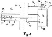
- Fig. 1 is shown part of a designed as a vacuum pump vacuum system.
- the vacuum pump includes a fluid channel 10 defining a flow path for a working medium, for example air.
- the fluid channel 10 is formed in a housing 12 of the vacuum pump.
- a fluid flow in the fluid passage 10 during operation of the vacuum pump in Fig. 1 from bottom to top, but also a reverse flow direction can be provided.
- valve slide 14 Arranged transversely to the fluid channel 10 is a valve slide 14 which at least partially opens or closes the fluid channel 10 as a function of its position.
- the valve spool 14 has a passage area 16, which in the in Fig. 1 shown position of the valve spool 14 is aligned with respect to the fluid channel 10, that is consistent with this in the flow direction. In other words shows Fig. 1 the valve spool in an open position.
- valve spool 14 is guided linearly in a guide 18, so that the valve spool 14 with respect to Fig. 1 can perform a horizontal movement.
- valve spool 14 designed as a spring 20 resetting device is provided.
- the spring 20 biases the valve spool 14 with respect to a housing wall 22.
- a membrane 24 separating member is provided at one of the return device opposite end of the valve spool 14 .
- the membrane 24 separates a working region defined by the fluid channel 10 at least from a control chamber 26.
- the control chamber 26 is defined by one side of the membrane 24 and by a control chamber 28.
- the control chamber 26 is sealed by the membrane 24 with respect to the fluid channel 10.
- connection 30 is provided to a switching device, which is designed in the present embodiment as a switching valve 32, in particular as a 3/2-way valve. From the switching valve 32, a connection 34 is provided to an ambient pressure. In addition, the switching valve 32 is connected via a connection 36 to the working area, wherein in the present embodiment, the connection 36 opens into an area downstream of the valve spool 14.
- the switching valve 32 is configured to selectively connect either the connection 36 to the connection 30, ie the fluid channel 10 to the control chamber 26, or the connection 34 to the connection 30, ie the ambient pressure with the control chamber 26.
- the switching valve 32 on a solenoid 38.
- the position or position of the valve slide 14 relative to the fluid channel 10 is dependent on a prevailing in the control chamber 26 control pressure which causes a force on the valve slide 14 against a spring force of the spring 20 via the diaphragm 24. Consequently, via the control pressure in the control chamber 26, the position of the valve spool 14 can be controlled substantially continuously.
- a high control pressure in the control chamber 26 puts the valve spool 14 in the in Fig. 1
- the valve spool 14 takes a different position, namely in Fig. 1 further to the right, one.
- the control chamber 26 can be fluidically connected by the switching valve 32 selectively with the fluid channel 10 or with the ambient pressure.
- the control pressure prevailing in the control chamber 26 can thus be adjusted or controlled.
- at least two different pressure levels in the control chamber 26 can be adjusted during operation of the vacuum pump, namely a first pressure corresponding to a pressure prevailing in the fluid passage 10, or a second pressure corresponding to an ambient pressure.
- intermediate pressures lying between the first and the second pressure and thus corresponding positions of the valve slide 14 in the illustrated embodiment can also be realized.
- the switching valve 32 in particular with relatively high frequency, periodically switch between the connections 34 and 36.
- the necessary switching frequency can be, for example, in an advantageous Decrease manner by one or more, for example, also adjustable in their permeability, throttles in the compounds 30, 34 and / or 36 are arranged.
- FIG. 2 A further embodiment of a part of a vacuum system designed as a vacuum pump is shown.
- a housing 12 of the vacuum pump defines a fluid channel 10, the in Fig. 2 left end defines an inlet 40 of the vacuum pump.
- the right end of the fluid channel 10 opens into a main flow path of the vacuum pump, in particular between two vacuum pumping stages, each of which may be configured, for example, as a turbo, Holweck, Siegbahn, Gaede or non-molecular pumping stage or combinations thereof.
- the fluid channel 10 is connected through a valve spool 14 as in FIG Fig. 2A Lockable and as shown in Fig. 2B shown to be releasable.
- the valve spool 14 is in Fig. 2A in a closed position and in Fig. 2B in an open position.
- the valve spool 14 is located at one end, in Fig. 2 at the upper end, on a designed as a rolling diaphragm 42 separating member. At its opposite end of the rolling diaphragm 42, a return spring 20 is provided for the valve spool 14, which biases the valve spool 14 in the direction of the rolling diaphragm 42 and in its open position.
- the rolling diaphragm 42 With a side facing away from the valve slide 14 side of the rolling diaphragm 42, the rolling diaphragm 42 at least partially defines a control chamber 26, which is further defined by a control chamber 28.
- a control pressure prevailing in the control chamber 26 is transmitted via the rolling diaphragm 42 to the valve spool 14, so that the position of the valve spool 14 is a function of the control pressure prevailing in the control chamber 26.
- the control pressure in the control room 26 can different manner, for example by one of the variants described herein, are set.
- a designed as a rolling diaphragm separating device allows a particularly large travel, especially in comparison to otherwise moderate dimensions of the separating element.
- the rolling diaphragm can additionally be used to seal the control chamber 26 with respect to the working area, in this case fluid channel 10.
- the rolling diaphragm 42 has a circumferential annular bead 44, which can be pressed in a similar manner to an O-ring between the control chamber 28 and the housing 12.
- the rolling diaphragm 42 conforms to the shape of the valve spool 14 and rolls laterally relative to this during a positioning movement. As a result, a precise power transmission is ensured.
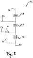
- FIG. 3 schematically an exemplary split-flow vacuum pump 46 is shown, which comprises two turbo vacuum pumping stages 48, 50 and a Holweck pumping stage 52, which are arranged in series and on a common rotor shaft.
- a main flow direction for a working medium, for example air, runs along the vertical axis in Fig. 3 from top to bottom.
- the split-flow vacuum pump 46 also has three inlets 54, 56, 58 and an outlet 60.
- the inlet 54 opens in the main flow direction before the turbo vacuum pumping stage 48, the inlet 56 between the turbo vacuum pumping stages 48 and 50 and the inlet 58 between the pumping stages 50 and 52.
- the inlets 54, 56, 58 are preferably connected to different recipients .
- the working medium conveyed from the inlets 54, 56, 58 is ejected via the common outlet 60 or, for example, forwarded to a backing pump, which is not shown separately.
- a valve 62 is arranged, which is designed to influence a conductance of the inlet 58.
- the valve 62 is designed as a pressure-controlled valve, i. the conductance of the inlet 58 is adjustable in response to a control pressure.
- a control line 64 is provided, which connects the pressure-controlled valve 62 to the outlet 60 in the present embodiment.
- the control line 64 thus communicates a pressure prevailing at the outlet 60 as a control pressure to the valve 62, which thus controls the conductance of the inlet 58 as a function of the pressure prevailing at the outlet 60.
- a valve in the manner of the valve 62 may, for example, also be arranged on one or more of the other inlets 54, 56. Alternatively or additionally, such a valve can also be arranged elsewhere, for example in the main flow path. In principle, any pressure which prevails, in particular in a vacuum system, can be used as control pressure. Also, for example, in the control line 64, a pressure control configuration, for example according to Fig. 1 , So for example, an additional connection to an ambient pressure and / or switching valve, be provided.
- a conductance-changing element such as the valve 62, can however be driven in different ways, for example, electromagnetically, hydraulically and / or via a shape memory actuator.
- a fluid flow may be controlled substantially independently of the other inlets 54, 56.
- performance parameters of the vacuum pump for the inlet 58 can be adjusted specifically and individually.
- the conductance of the inlet 58 can be set particularly low if there is a high absolute pressure at the inlet 58 or in the corresponding recipient, which could damage individual vacuum components, such as the pumping stages 50, 52.
- a pumping speed provided at the inlet 58 may be adjusted as needed.
- evacuation of the recipient connected to the inlet 58 may optionally be delayed more or less as compared to the other inlets 54, 56.
- the influencing of the fluid flow in certain sections of the vacuum pump proves to be advantageous in particular in connection with a split-flow vacuum pump, in particular if different pump stages of the vacuum pump are arranged on a common rotor.
- Fig. 4 There is shown a split-flow vacuum pump 100 having a plurality of inlets 102, three in this embodiment. Two of the inlets 102 are shown with protective grille 104 attached, the in Fig. 4 left inlet 102 is shown for improving the visibility of the interior of the vacuum pump 100 without guard.
- the vacuum pump 100 has an elongated recess in the region of the left inlet 102 108, which extends substantially parallel to a rotor axis of the rotor 106.
- the recess 108 is delimited on the longitudinal side by two edges 110, which each form an obstacle which prevents a rotor part which has been released in the event of a fault from escaping from the inlet 102.
- the other inlets 102 may also include such or other obstruction means.
- the edges 110 are arranged in an expected trajectory of a loosened rotor part substantially as its first obstacle and thus provide for a deflection of the rotor part away from the inlet.
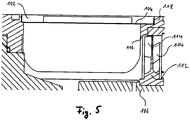
- Fig. 5 shows a sectional view of another split-flow vacuum pump, wherein the cutting plane along a rotor axis of a rotor 106 extends. In this case, however, only one part of the vacuum pump associated with an inlet 102 is shown.
- the inlet 102 is provided with a protective grid 104.
- the rotor 106 includes a plurality of rotor disks 112, of which, however, in FIG Fig. 5 only one is shown.
- the rotor disk 112 includes a plurality of circumferentially spaced rotor blades 114 that rotate about the rotor axis at high speed during operation of the vacuum pump with the rotor 106.
- the rotor blades 114 can break off in the event of a fault and then fly at a correspondingly high speed through the interior of the vacuum pump and also in the direction of the inlet 102. This may pose a hazard, for example, to sensitive devices in a recipient, not shown, connected to the inlet 102.
- An edge 116 is provided which forms an obstacle.
- the edge 116 is formed as around the rotor axis extending edge. It extends the edge 116 along an inner surface of a housing part 118 along and is integrally formed thereon.
- the edge 116 is also in a pumping direction, which in Fig. 5 from the top through the inlet 102 into the interior of the vacuum pump and then past the rotor blades 114 to the right, disposed between the inlet 102 and the rotor blades 114.
- the edge 116 thus acts as a first obstacle for a rotor blade 114 which is released in the event of a fault and causes a deflection of the rotor blade away from the inlet 102.
- the edge 116 is formed in the present embodiment as completely around the rotor 106 extending edge. In an alternative embodiment, however, the edge 116 may also extend only over a partial angle range with respect to the rotor axis, wherein the partial angle range is aligned in particular in the direction of the inlet 102.
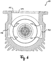
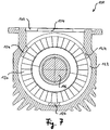
- a further embodiment of a split-flow vacuum pump 100 is shown in a sectional view transverse to a rotor axis.
- the sectional view shows an inlet 102, which is also equipped with a protective grid 104.
- the vacuum pump 100 has two recesses 108, each extending parallel to the rotor axis.
- a respective recess 108 is formed as a rectangular groove and laterally bounded by edges 110, which act as a means of preventing dissolved in case of failure rotor parts.
- Fig. 7 an alternative embodiment of a split-flow vacuum pump 100 is also shown in a cross-sectional view transverse to a rotor axis of a rotor 106. Also, the vacuum pump 100 of Fig. 7 has an inlet 102 with a protective grid 104. In Fig. 7 In addition, a plurality of stator blades 120 of a stator disk are visible.
- the vacuum pump 100 of Fig. 7 also has an obstacle, which in this embodiment, however, is designed as a spacer ring 122 with three webs 124.
- the spacer ring 122 serves to define a distance between two stator disks successive along the rotor axis. In the axial direction from the image plane of the Fig. 7 out so at least one more stator is provided.
- the inlet 102 is not a first inlet of the split-flow vacuum pump but, for example, a central inlet 102, for example corresponding to the central inlet 102 of FIG Fig. 4 ,
- the webs 124 of the spacer ring 122 are arranged at an angular distance of about 120 °, although other angular distances and other numbers of webs 124 may be provided.
- Two webs 124 each form a free space in the circumferential direction between each other.
- the in Fig. 7 Upper free space is facing the inlet 102 in order to ensure a good permeability to be pumped process gas, ie a good conductance.
- Free-spaces oriented to the lower left and lower right are bounded by the respective webs 124 and the webs 124 form a plurality of edges with which dissolved rotor parts can collide, so that the rotor parts are deflected or their kinetic energy is reduced.
- FIG. 8 2 a schematic of another embodiment of a split-flow vacuum pump 100 having three inlets 102 is shown.
- a rotor 106 has a plurality of turbo vacuum pump stages ("turbo stages") 126, which are respectively arranged in the pumping direction behind one of the inlets 102.
- a respective turbo stage 126 has a plurality of rotor blades, which are arranged in at least one rotor plane. The rotor blades or the rotor planes are arranged axially offset from the inlets 102.
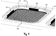
- FIG. 9 an inlet 102 of another exemplary split-flow vacuum pump is shown, which is provided with a protective grid 104.
- the guard 104 has four retaining tabs 128 which hold the guard 104 in place via an elastic return force acting against each wall of the inlet 102.
- the retaining tabs 128 are in Fig. 9 however, only two retaining tabs 128 are visible due to the perspective. The remaining retaining tabs 128 are opposite to those shown.
- the inlet 102 is provided for sealing with a circumferential groove 130 for an O-ring, not shown.
- edges 132 At the inlet 102, two obstruction means formed as edges 132 partially surrounding the inlet 102 are provided.
- a respective edge 130 forms a fixing projection, which secures one of the retaining tabs 128 against displacement upwards.
- the opposite edge 130 which secures the invisible retaining tab 128.
- the guard 104 is against displacement upwards, ie in a recipient, secured and dissolved in case of failure rotor parts are effectively held by the secure guard 104 in the vacuum pump.
- one edge may also be used for a plurality of retaining tabs 128 or e.g. be provided an at least substantially completely circumferential edge.
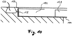
- Fig. 10 the function of the edge 132 is further illustrated in a sectional view.
- the edge 132 prevents the retaining tab 128 and thus the protective grid 104 from moving upwards, ie into the recipient.
- the retaining tab 128 is formed integrally with the remaining protective grid 104 and snaps when mounting the protective grid 104 from above under the edge 132 a.
- the guard 104 can therefore be easily mounted, the recipient is in front of dissolved rotor parts protected and there are no additional fasteners such as screws necessary.
- top and bottom used herein are for the illustrations only. The objects shown may also have other orientations in practice.
Landscapes
- Engineering & Computer Science (AREA)
- Mechanical Engineering (AREA)
- General Engineering & Computer Science (AREA)
- Physics & Mathematics (AREA)
- General Physics & Mathematics (AREA)
- Non-Positive Displacement Air Blowers (AREA)
- Compressors, Vaccum Pumps And Other Relevant Systems (AREA)
Abstract
Description
- Die vorliegende Erfindung betrifft ein Vakuumsystem, insbesondere Vakuumpumpe oder Anordnung aus zumindest einem Vakuumgerät, bevorzugt einer Vakuumpumpe, und wenigstens einem Rezipienten, bevorzugt einer Vakuumkammer oder einem Messgerät wie z.B. einem Elektronenmikroskop. Weiterhin betrifft die Erfindung Verfahren zum Betreiben eines Vakuumsystems, insbesondere eines Vakuumsystems wie hierin beschrieben.
- Außerdem betrifft die Erfindung eine Turbomolekularvakuumpumpe, insbesondere Splitflow-Pumpe, mit einem Gehäuse, welches zumindest einen Einlass zum Anschluss der Pumpe an einen Rezipienten aufweist, und einem in dem Gehäuse angeordneten, sich während des Betriebs um eine Rotorachse drehenden Rotor, der in wenigstens einer Rotorebene eine Mehrzahl von in Umfangsrichtung beabstandet angeordneten Rotorschaufeln aufweist.
- Vakuumgeräte haben bestimmungsgemäß in vielen Fällen mindestens einen abgeschlossenen oder mit anderen Geräten verbundenen Innenraum, dessen Absolutdruck unterhalb eines Umgebungsdrucks, z.B. eines Atmosphärendrucks, der Geräteumgebung liegt. In Ausnahmefällen kann ein Gerät auch innerhalb einer Gesamtanlage in einem Vakuumraum angeordnet sein und im Inneren z.B. Vorrichtungen aufweisen, die auf einem anderen Druckniveau als dem des Vakuumraums, sowohl niedriger, gleich oder auch höher dem atmosphärischen Umgebungsdruck der Gesamtanlage, betrieben werden.
- Es ist eine Aufgabe der Erfindung, ein einfach und/oder flexibel betreibbares und/oder betriebssicheres Vakuumsystem sowie ein einfaches und/oder flexibles Verfahren zum Betreiben eines Vakuumsystems zu schaffen.
- Gemäß einem ersten Aspekt der Erfindung umfasst ein Vakuumsystem einen Arbeitsbereich, ein Trennorgan und einen Steuerraum, welcher durch das Trennorgan von dem Arbeitsbereich getrennt ist und in welchem ein relativ zum Druck im Arbeitsbereich veränderbarer Steuerdruck herrscht. Dabei ist durch Verändern des Steuerdrucks mittels des Trennorgans eine Arbeitsbewegung im Arbeitsbereich durchführbar.
- Das erfindungsgemäße Vakuumsystem, bei dem es sich insbesondere um eine Vakuumpumpe handeln kann, erlaubt eine besonders kompakte Bauart, einen einfachen Aufbau und, insbesondere mit den vorstehenden Vorteilen einhergehend, geringe Herstellungskosten, insbesondere gegenüber einer Verwendung eines gewöhnlichen, beispielsweise elektromagnetisch betriebenen Aktors, z.B. Stellmotor oder Hubmagnet.
- Die Arbeitsbewegung lässt sich erfindungsgemäß zumindest in der Nähe des Arbeitsbereichs ohne Erzeugung von elektrischen Feldern oder Magnetfeldern bewirken. Hierdurch werden gegebenenfalls im Arbeitsbereich vorhandene elektromagnetisch empfindliche Elemente, wie z.B. Elektronenmikroskope, nicht negativ beeinflusst.
- Die Nutzung eines Steuerdrucks führt zu einer geringen Leistungsaufnahme zur Bewirkung der Arbeitsbewegung und trägt somit zu einer guten Energieeffizienz des Vakuumsystems und zu einer geringen Wärmegeneration im Arbeitsbereich bei.
- Gemäß einer Ausführungsform ist der Arbeitsbereich ein Vakuumbereich. Insbesondere kann der Vakuumbereich im Betrieb des Vakuumsystems einen Druck aufweisen, der niedriger ist als ein Umgebungsdruck des Vakuumsystems.
- Beispielsweise kann nur das Trennorgan die Arbeitsbewegung durchführen.
- Zusätzlich oder alternativ kann das Trennorgan durch seine Arbeitsbewegung eine Arbeitseinrichtung, beispielsweise einen Schieber, Hebel oder Schalter, beaufschlagen, insbesondere mechanisch, pneumatisch, hydraulisch, elektrisch und/oder magnetisch. Die Beaufschlagung muss keine Arbeitsbewegung zusätzlich zu jener des Trennorgans zur Folge haben, d.h. die beaufschlagte Arbeitseinrichtung muss sich selbst nicht bewegen. Beispielsweise kann ein elektrisch leitfähiges Trennorgan einen elektrischen Kontakt zwischen zwei Bereichen einer stationären Arbeitseinrichtung herstellen.
- Bei einer anderen Ausführungsform veranlasst das Trennorgan durch Zusammenwirken mit einer Arbeitseinrichtung diese zu einer Arbeitsbewegung.
- Bei einer weiteren Ausführungsform umfasst die Arbeitseinrichtung einen Verschluss, eine Klappe, ein Ventil, eine Ventilkomponente, ein Wälz- oder Magnetlager oder eine Komponente eines Wälz- oder Magnetlagers.
- Der Arbeitsbereich kann zumindest einen Strömungspfad, insbesondere einen Fluidkanal, für ein Arbeits- oder Betriebsfluid, umfassen, wobei durch die Arbeitsbewegung die Fluidströmung entlang des Strömungspfades beeinflussbar ist. Grundsätzlich kann das Arbeitsfluid ein beliebiges Gas oder eine beliebige Flüssigkeit sein oder umfassen. Zum Beispiel kann das Arbeitsfluid Luft sein oder umfassen. Das Betriebsfluid kann beispielsweise Öl, z.B. Schmieröl, sein oder umfassen.
- Bei einer Weiterbildung ist durch die Arbeitsbewegung ein Strömungsquerschnitt des Strömungspfades an zumindest einer Arbeitsstelle veränderbar.
- Das Trennorgan kann beispielsweise außerhalb des Arbeitsbereiches angeordnet sein.
- Alternativ oder zusätzlich kann die Arbeitsbewegung eine Bewegung des Trennorgans in den Arbeitsbereich hinein umfassen.
- Bei einer weiteren Ausführungsform beeinflusst die Arbeitsbewegung den Arbeitsbereich, insbesondere lediglich, passiv. Der Begriff "passiv" kann im Zusammenhang mit der vorliegenden Erfindung bedeuten, dass die Beeinflussung im Wesentlichen frei von Leistungsübertragung auf ein im Arbeitsbereich befindliches Arbeitsmedium und/oder energieneutral in Bezug auf das Arbeitsmedium ist. Insbesondere kann eine passive Beeinflussung bewirken, dass ein Arbeitsmedium bezüglich einer Strömung des Arbeitsmediums lediglich mehr oder weniger behindert wird. Beispielsweise kann, insbesondere lediglich, eine Querschnittsveränderung eines im Arbeitsbereich befindlichen Fluidkanals bewirkt werden, um den Arbeitsbereich passiv zu beeinflussen.
- Bei einer weiteren Ausführungsform löst die Arbeitsbewegung im Arbeitsbereich einen Betätigungsvorgang aus oder führt diesen selbst aus.
- Ebenfalls kann mit Vorteil vorgesehen sein, dass das Trennorgan als Schalter betreibbar ist, insbesondere als bistabiler Schalter.
- Bei einer Weiterbildung ist das Trennorgan durch Verändern des Steuerdrucks zwischen wenigstens zwei Schaltstellungen bewegbar. Weiterhin kann das Trennorgan auch stufenlos bewegbar oder betätigbar sein.
- Das Trennorgan kann auch zu einer linearen Bewegung oder zu einer Bewegung mit einem nicht-linearen Bewegungsprofil ansteuerbar sein.
- Bei einer weiteren Ausführungsform weist das Trennorgan eine Rückstellfunktion auf. Beispielsweise kann das Trennorgan durch die Rückstellfunktion stets in einem definierten Zustand in Abhängigkeit von einem Druck im Steuerraum gehalten werden.
- Alternativ oder zusätzlich kann für das Trennorgan eine Rückstelleinrichtung, z.B. Feder, vorgesehen sein.
- Gemäß einer Weiterbildung ist das Trennorgan durch Umkehren des Steuerdrucks rückstellbar.
- Es kann vorgesehen sein, dass eine Verbindung zwischen dem Steuerraum und dem Arbeitsbereich vorgesehen ist, die einen im Arbeitsbereich herrschenden Druck an den Steuerraum kommuniziert. Bei dem Druck kann es sich um einen Druck handeln, der im Arbeitsbereich dann herrscht, wenn das Vakuumsystem in Betrieb ist, z.B. während des Betriebs einer Vakuumpumpe.
- Bei einer weiteren Ausführungsform ist ein Druck im Arbeitsbereich von einem Umgebungsdruck verschieden, insbesondere kleiner als ein Umgebungsdruck.
- Es kann ebenfalls vorteilhaft sein, wenn gemäß einer weiteren Ausführungsform eine Verbindung einen am Auslass einer Vakuumpumpe herrschenden Druck an den Steuerraum kommuniziert. Die Verbindung kann beispielsweise bezüglich einer Durchlässigkeit bzw. eines Leitwerts steuerbar sein.
- Bei einer Weiterbildung ist eine Vorvakuumpumpe vorgesehen, um am Auslass der Vakuumpumpe ein Vorvakuum zu erzeugen, und die Verbindung kommuniziert einen Vorvakuumdruck an den Steuerraum.
- Weitere Vorteile ergeben sich, wenn gemäß einer weiteren Ausführungsform für den Steuerraum eine erste Verbindung zu einem ersten Bereich mit einem ersten Druck und eine zweite Verbindung zu einem zweiten Bereich mit einem zweiten Druck vorgesehen sind, wobei zumindest eine, insbesondere beide, der Verbindungen bezüglich einer Durchlässigkeit oder eines Leitwerts steuerbar ist. Die Verbindungen können beispielsweise auch durch ein gemeinsames Steuerorgan, z.B. ein Schaltventil, steuerbar sein.
- Bei einer weiteren Ausführungsform ist in zumindest einer der Verbindungen eine oder eine den Verbindungen gemeinsame Drossel zum Drosseln der Kommunikation des jeweiligen Drucks an den Steuerraum vorgesehen. Die Drossel kann ebenfalls bezüglich ihrer Drosselwirkung steuerbar sein.
- Alternativ oder zusätzlich kann eine Schaltvorrichtung vorgesehen sein, mittels derer wahlweise ein erster Druck oder ein von dem ersten Druck verschiedener zweiter Druck an den Steuerraum kommunizierbar ist.
- Insbesondere kann der erste oder der zweite Druck ein an einem Auslass einer Vakuumpumpe herrschender Druck sein.
- Alternativ oder zusätzlich kann der erste oder der zweite Druck ein Umgebungsdruck sein.
- Bei einer weiteren Ausführungsform ist für den Steuerraum eine steuerbare Verbindung zu einem Umgebungsdruck vorgesehen.
- Das Trennorgan kann beispielsweise als eine Membran ausgebildet sein oder eine Membran umfassen.
- Das Trennorgan kann beispielsweise auch eine Rollmembran und/oder metallische Membran sein und/oder flexibel, planar, taschenförmig, wellbalgartig und/oder ein- oder mehrlagig ausgebildet sein.
- Gemäß einem weiteren Beispiel kann ein Ventil vorgesehen sein, welches in einem Fluidkanal angeordnet und durch ein als Membran ausgeführtes Trennorgan steuerbar ist. Das Trennorgan kann alternativ oder zusätzlich zum Steuern des Fluidflusses im Fluidkanal ein Ventilelement bewegen. Alternativ oder zusätzlich kann das Trennorgan zum Steuern des Fluidflusses selbst einen Querschnitt eines Fluidkanals verändern.
- Für die Arbeitsbewegung kann z.B. eine Endlagenabfrage vorgesehen sein. Eine Endlageninformation kann beispielsweise von einer Steuerungseinrichtung des Vakuumsystems verarbeitet und/oder genutzt werden.
- Gemäß einem zweiten Aspekt der Erfindung umfasst ein Vakuumsystem, insbesondere Vakuumpumpe oder Anordnung aus zumindest einem Vakuumgerät, bevorzugt einer Vakuumpumpe, und wenigstens einem Rezipienten, bevorzugt einer Vakuumkammer oder einem Messgerät wie z.B. einem Elektronenmikroskop, insbesondere nach einem der vorhergehenden Ansprüche, zumindest einen Strömungspfad für ein Arbeits- oder Betriebsfluid, und eine Einrichtung, die dazu ausgebildet ist, die Fluidströmung entlang des Strömungspfades an zumindest einem Abschnitt des Strömungspfades zu beeinflussen.
- Dies erlaubt in einfacher Weise ein besonders flexibel ansteuerbares Vakuum-system.
- Bei einer Ausführungsform umfasst die Einrichtung wenigstens ein Stellorgan, das zum Beeinflussen der Fluidströmung zu einer Stellbewegung ansteuerbar ist.
- Bei einer weiteren Ausführungsform ist die Einrichtung dazu ausgebildet ist, einen Strömungsquerschnitt des Strömungspfades an dem Abschnitt zu verändern.
- Weiterhin ist es vorteilhaft, wenn gemäß einem weiteren Ausführungsbeispiel die Einrichtung dazu ausgebildet ist, einen Leitwert des Strömungspfades an dem Abschnitt zu verändern. Beispielsweise kann der Leitwert durch ein Trennorgan selbst oder durch ein von einem Trennorgan bewegtes Element veränderbar sein. Der Leitwert kann beispielsweise auch durch Betätigung eines Ventils veränderbar sein. Das Ventil kann beispielsweise in dem Abschnitt angeordnet sein und den Abschnitt wahlweise zumindest teilweise öffnen oder schließen. Insbesondere kann das Ventil druckgesteuert sein, insbesondere durch einen Druck am Auslass einer Vakuumpumpe.
- Bei einer Weiterbildung ist oder umfasst das Vakuumsystem eine Vakuumpumpe, wobei die Vakuumpumpe zumindest einen Einlass zum Einlassen von zu förderndem Arbeitsfluid aus einem Rezipienten und einen Auslass zum Ausstoßen des zu fördernden Arbeitsfluids aufweist, wobei der Strömungspfad zwischen Einlass und Auslass der Vakuumpumpe definiert ist.
- Insbesondere kann der Abschnitt an einem Einlass einer Vakuumpumpe angeordnet sein oder den Einlass bilden.
- Der Abschnitt kann an zumindest einem von mehreren Einlässen einer Vakuumpumpe angeordnet sein. Insbesondere kann es sich bei der Vakuumpumpe um eine sogenannte Splitflow-Vakuumpumpe handeln. Dieser Typ von Vakuumpumpe ist dem Fachmann bekannt, sodass hierauf nicht näher eingegangen zu werden braucht. Beispielsweise kann der eine von mehreren Einlässen zwischen zwei Pumpstufen der Vakuumpumpe in einen Hauptströmungspfad münden. Die Pumpstufen können jeweils beispielsweise als eine Turbo-, Holweck-, Siegbahn-, Gaede- oder nichtmolekulare Pumpstufe oder Kombinationen hiervon ausgebildet sein.
- Durch Beeinflussen der Fluidströmung an dem Abschnitt kann beispielsweise zumindest ein Leistungsparameter der Vakuumpumpe für den jeweiligen Einlass, insbesondere im Wesentlichen unabhängig von weiteren Einlassen, einstellbar sein.
- Bei einer Ausführungsform können sich unterschiedliche Druckniveaus in einem am betreffenden Einlass angeschlossenen Rezipienten einstellen lassen. Ein derart ausgestaltetes Vakuumsystem lässt sich besonders flexibel und unter vielen unterschiedlichen Betriebsszenarien bedarfsgerecht betreiben.
- Bei einer Weiterbildung ist die Einrichtung dazu ausgebildet, einen offenen Querschnitt in dem Abschnitt des Strömungspfades in seiner Größe zu verändern, um die Fluidströmung zu beeinflussen.
- Die Größe des offenen Querschnitts kann auf zumindest zwei unterschiedliche Werte einstellbar sein.
- Die Größe des offenen Querschnitts kann auch zumindest im Wesentlichen stufenlos einstellbar sein.
- Bei einer weiteren Ausführungsform umfasst die Einrichtung ein Trennorgan und einen Steuerraum gemäß einer unter dem ersten Aspekt der Erfindung beschriebenen Ausführungsform, wobei der Abschnitt des Strömungspfads dem Arbeitsbereich entspricht oder Teil des Arbeitsbereichs ist und mittels der Arbeitsbewegung die Fluidströmung an dem Abschnitt beeinflussbar ist.
- Unter dem zweiten Aspekt der Erfindung lassen sich insbesondere verschiedene Fluidströmungen im Wesentlichen unabhängig voneinander ansteuern. So kann beispielsweise an unterschiedlichen Abschnitten von, insbesondere unterschiedlichen, Strömungspfaden zumindest ein jeweiliger Leitwert zumindest im Wesentlichen unabhängig von anderen Abschnitten eingestellt werden. Hierdurch lässt sich das Vakuumsystem besonders flexibel und angepasst an verschiedenste Betriebsszenarien betreiben.
- Beispielsweise können so unterschiedliche Drücke an einem von mehreren Einlässen, insbesondere im Wesentlichen unabhängig von anderen Einlässen, eingestellt werden. Beispielsweise ist es auch möglich, für einen Einlass bzw. Rezipienten einen Leitwert zu verringern, um beispielsweise die Vakuumpumpe oder das Vakuumsystem vor einem in dem betreffenden Rezipienten herrschenden hohen Druck zu schützen. Auch kann das Vakuumsystem, beispielsweise durch Schließen eines Ein- oder Auslasses, vor Partikeln, Stäuben, Ölen oder sonstigen zu erwartenden Störelementen, welche aus dem Rezipienten stammen können, geschützt werden. Andersherum kann auch ein Rezipient vor dem Vakuumsystem entstammenden Störelementen geschützt werden, wie z.B. unerwünscht austretendem Öl oder einem in einem Fehlerfall, insbesondere einer inneren Kollision, gelösten Rotorteil. Ferner kann beispielsweise beim Anfahren eines Vakuumsystems gezielt einstellbar sein, welcher Rezipient welche Pumpleistung erfährt, also z.B. welcher Rezipient stärker oder schneller abgepumpt wird. Alternativ oder zusätzlich kann ein Druck an einem Abschnitt, Einlass und/oder Rezipient durch die erfindungsgemäße Beeinflussung steuerbar sein. Grundsätzlich kann eine Fluiddurchlässigkeit bzw. ein Leitwert des Abschnitts stufenweise oder stufenlos einstellbar sein, insbesondere in Abhängigkeit von Betriebszuständen oder Parametern des Vakuumsystems, wie beispielsweise einem Druck, insbesondere Vorvakuumdruck. Alternativ oder zusätzlich kann beispielsweise eine Flutfestigkeit für einen betreffenden Rezipienten, insbesondere individuell, einstellbar sein.
- Die erfindungsgemäße Beeinflussung kann beispielsweise durch eine elektronische Steuerung gesteuert werden. Es ist jedoch auch vorteilhaft möglich, die Beeinflussung ausschließlich mechanisch, insbesondere durch einen als Steuerdruck für die Beeinflussung verwendeten Druck im oder am Vakuumsystem, durchzuführen. Auch eine Kombination einer mechanischen Steuerung und einer elektronischen Steuerung ist möglich.
- Die Einrichtung, welche die Fluidströmung beeinflusst, kann beispielsweise ein Ventil, ein, insbesondere bewegliches, Schutzgitter, eine Anordnung mit beweglichen Lamellen, eine Iris und/oder eine Mehrzahl und/oder Kombination der genannten Elemente umfassen, wobei die Elemente insbesondere relativ zu einander beweglich sein können. In einem anschaulichen Beispiel lassen sich zwei in Strömungsrichtung kurz hintereinander angeordnete Schutzgitter relativ zueinander quer zur Strömungsrichtung verschieben, sodass hierdurch die Durchlässigkeit bzw. der Leitwert des betreffenden Abschnitts einstellbar ist.
- In einem weiteren Beispiel kann die Einrichtung im Bereich eines Einlasses einer Vakuumpumpe derart angeordnet und/oder ausgebildet sein, insbesondere als ein Hinderungsmittel ausgebildet sein, welches derart angeordnet und/oder ausgebildet ist, dass ein in einem Fehlerfall gelöstes Rotorteil, insbesondere eine Rotorschaufel oder ein Fragment einer Rotorschaufel, daran gehindert oder dabei behindert wird, aus dem Einlass auszutreten.
- Die Beeinflussungseinrichtung kann beispielsweise Teil einer Vakuumpumpe oder aber Teil eines zusätzlichen Elements sein. Beispielsweise kann die Einrichtung an einem Einlass einer Vakuumpumpe angeordnet sein und z.B. entweder als ein der Vakuumpumpe eigenes Element ausgebildet sein oder durch ein zusätzliches Element, wie z.B. ein an einen Einlassflansch anbringbares Element, z.B. ein Leitungselement, sein. Es ist also beispielsweise auch möglich, insbesondere im Hinblick auf ein zusätzliches Element als Beeinflussungeinrichtung oder als ein Teil davon, eine Nachrüstung für ein bestehendes Vakuumsystem bereitzustellen.
- Der Abschnitt des Strömungspfades kann beispielsweise auch ein Bypass des Vakuumsystems sein.
- Bei einer beispielhaften Anwendung kann ein möglichst hohes Saugvermögen an einem Rezipienten einer Vakuumpumpe, insbesondere mit mehreren Einlassen, benötigt werden, beispielsweise um eine initiale Evakuierungszeit für den betreffenden Rezipienten zu verringern. Auch kann ein definierter Druck benötigt werden, wobei ein Saugvermögen eine nötige einzulassende Gaslast bestimmt. Die Gaslast beeinflusst weiterhin den Energieverbrauch und die Abwärme der Vakuumpumpe. Durch eine Drosselung des Saugvermögens kann die Gaslast reduziert und somit können Energieverbrauch und Abwärme reduziert werden.
- Gemäß einem dritten Aspekt der Erfindung wird ein Verfahren zum Betreiben eines Vakuumsystems vorgestellt. Das Vakuumsystem kann insbesondere eine Vakuumpumpe oder Anordnung aus zumindest einem Vakuumgerät, bevorzugt einer Vakuumpumpe, und wenigstens einem Rezipienten, bevorzugt einer Vakuumkammer oder einem Messgerät wie z.B. einem Elektronenmikroskop, sein. Insbesondere kann es sich um ein Vakuumsystem gemäß einer oder einer Kombination von hierin beschriebenen Ausführungsformen von Vakuumsystemen handeln. Bei dem Verfahren wird eine Fluidströmung von Arbeit- oder Betriebsfluid entlang eines Strömungspfades in Abhängigkeit von einem in dem Vakuumsystem, insbesondere in einem Vakuumbereich, herrschenden Druck beeinflusst.
- Ein vierter Aspekt der Erfindung betrifft ein Verfahren zum Betreiben eines eine Vakuumpumpe umfassenden Vakuumsystems, wobei die Vakuumpumpe zumindest zwei Einlässe und wenigstens einen Auslass umfasst und zwischen einem jeweiligen Einlass und dem oder einem jeweiligen Auslass jeweilige, zumindest teilweise voneinander verschiedene Strömungspfade definiert, und wobei eine Fluidströmung in zumindest einem Strömungspfad, insbesondere individuell, beeinflusst wird. Insbesondere kann es sich um ein Vakuumsystem oder um eine Vakuumpumpe gemäß einer oder einer Kombination von hierin beschriebenen Ausführungsformen von Vakuumsystemen und Vakuumpumpen handeln.
- Gemäß einem fünften Aspekt der Erfindung wird die Aufgabe durch eine Turbomolekularpumpe gelöst, die sich insbesondere dadurch auszeichnet, dass im Bereich des Einlasses zumindest ein Hinderungsmittel vorgesehen ist, welches derart angeordnet und/oder ausgebildet ist, dass ein in einem Fehlerfall gelöstes Rotorteil, insbesondere eine Rotorschaufel oder ein Fragment einer Rotorschaufel, daran gehindert oder dabei behindert wird, aus dem Einlass auszutreten.
- Empfindliche Objekte im Einflussbereich der Turbomolekularpumpe werden somit vor gelösten und insbesondere mit hoher Geschwindigkeit umherfliegenden Rotorteilen geschützt. Auch wenn es durch das Hinderungsmittel beispielsweise nicht vollkommen ausgeschlossen werden kann, dass das Rotorteil das empfindliche Objekt im Einflussbereich der Turbopumpe erreicht und beschädigt, wird durch das Hinderungsmittel zumindest die Wahrscheinlichkeit hierfür verringert und/oder die Geschwindigkeit der Rotorteile reduziert, so dass insgesamt eine höhere Sicherheit für die empfindlichen Objekte gewährleistet ist und somit die Betriebssicherheit der erfindungsgemäßen Pumpe erhöht wird.
- Der Einflussbereich der Turbomolekularvakuumpumpe kann beispielsweise einen an den Einlass angeschlossenen Rezipienten umfassen. Die empfindlichen Objekte können beispielsweise, insbesondere in dem Rezipienten befindliche, empfindliche Geräte umfassen.
- Bei einer Ausführungsform ist das Hinderungsmittel in einer erwarteten Flugbahn eines gelösten Rotorteils als dessen erstes Hindernis angeordnet und zur Umlenkung des Rotorteils weg von dem Einlass ausgebildet.
- Gemäß einer weiteren Ausführungsform kann das Hinderungsmittel dazu ausgebildet sein, durch Kollision dem Rotorteil kinetische Energie zu nehmen.
- Das Hinderungsmittel kann zum Beispiel als Vorsprung oder Kante, insbesondere als eine Fangkante, ausgebildet sein. Alternativ oder zusätzlich kann das Hinderungsmittel an einer Innenfläche des Gehäuses angeordnet sein. Grundsätzlich kann das Hinderungsmittel z.B. länglich ausgebildet sein.
- Bei einer Weiterbildung erstreckt sich das Hinderungsmittel an einer Innenfläche des Gehäuses entlang um die Rotorachse herum.
- Bei noch einer Weiterbildung erstreckt sich das Hinderungsmittel nur über einen Teilumfang der Innenfläche um die Rotorachse herum. Hierdurch kann das Hinderungsmittel gezielt an einem bestimmten Teilumfang eingesetzt werden, um gelöste Rotorteile aufzuhalten, wobei aber am übrigen Teilumfang eine glatte Oberfläche vorgesehen sein kann, sodass sich in diesem übrigen Teilumfang der Leitwert der Vakuumpumpe nicht verschlechtert. Es lässt sich also ein gezielter Kompromiss aus erhöhter Sicherheit und nur unwesentlich verschlechtertem Leitwert erreichen. Insbesondere kann der Teilumfang radial in Richtung des Einlasses ausgerichtet sein. So kann sich das Hinderungsmittel beispielsweise zumindest über einen Winkelbereich erstrecken, der sich mit einem Winkelbereich des Einlasses in Bezug auf die Rotorachse im Wesentlichen deckt.
- Das Hinderungsmittel kann beispielsweise bezüglich einer Pumprichtung in einem Bereich zwischen dem Einlass und den Rotorschaufeln angeordnet sein. Alternativ oder zusätzlich kann sich das Hinderungsmittel zumindest im Wesentlichen quer zu oder entlang einer Pumprichtung erstrecken. Unabhängig hiervon kann sich das Hinderungsmittel zumindest im Wesentlichen quer oder axial in Bezug auf die Rotorachse erstrecken.
- Bei einer weiteren Ausführungsform ist das Hinderungsmittel durch eine, insbesondere längliche, Ausnehmung gebildet.
- Bei einer Weiterbildung ist der Einlass mit einem Schutzgitter versehen. Dabei ist das Hinderungsmittel insbesondere dazu ausgebildet, das Schutzgitter gegen eine Verschiebung durch ein gelöstes Rotorteil zu sichern. Hierfür kann das Hinderungsmittel das Schutzgitter vorteilhafterweise formschlüssig sichern und beispielsweise eine Rastvorrichtung, Schnappkante und/oder einen Fixiervorsprung für das Schutzgitter umfassen. So lassen sich separate Befestigungsmittel, z.B. Schrauben, vermeiden, die beispielsweise Luft einschließen und so die Qualität oder Güte des zu erreichenden Vakuums gefährden könnten.
- Das Hinderungsmittel kann zum Beispiel als integraler Teil eines Gehäuses der Turbopumpe oder alternativ als separates Bauteil oder an einem solchen ausgebildet sein. Das Hinderungsmittel kann zum Beispiel länglich sein und/oder sich quer oder axial in Bezug auf eine Pumprichtung und/oder den Rotor erstrecken.
- Die Sicherheit gegen Austritt von Rotorteilen aus dem Einlass lässt sich weiter verbessern, indem die Rotorschaufeln außerhalb eines Einlassbereichs der Vakuumpumpe angeordnet sind. Insbesondere im Fall einer Splitflow-Vakuumpumpe können die Rotorschaufeln z.B. in axialer Richtung versetzt zu jeglichen Einlässen angeordnet sein.
- Das Hinderungsmittel kann beispielsweise beweglich und/oder dynamisch ausgebildet sein. Alternativ kann das Hinderungsmittel aber auch starr und/oder statisch ausgebildet sein. Beispielsweise kann das Hinderungsmittel auch dazu ausgebildet sein, eine Fluidströmung entlang eines Strömungspfades an zumindest einem Abschnitt des Strömungspfades zu beeinflussen. So lassen sich beispielsweise der fünfte Aspekt der Erfindung und der zweite Aspekt der Erfindung und auch gegebenenfalls ihre hierin beschriebenen Ausführungsformen vorteilhaft kombinieren.
- In einem weiteren Beispiel kann ein bewegliches Hinderungsmittel beispielsweise auch durch ein Trennorgan angetrieben und/oder gesteuert werden, welches einen Steuerraum von einem Arbeitsbereich der Vakuumpumpe trennt. Dabei kann insbesondere im Steuerraum ein relativ zum Druck im Arbeitsbereich veränderbarer Steuerdruck herrschen, wobei durch Verändern des Steuerdrucks mittels des Trennorgans eine Arbeitsbewegung im Arbeitsbereich durchführbar ist.
- Grundsätzlich lassen sich die hierin beschriebenen Aspekte der Erfindung und ihre jeweiligen Ausführungsformen vorteilhaft untereinander kombinieren. Beispielsweise kann eine gemäß dem zweiten Aspekt vorgesehene Einrichtung zur Beeinflussung einer Fluidströmung als ein unter dem ersten Aspekt der Erfindung beschriebenes, mit einem Steuerdruck beaufschlagbares Trennorgan ausgeführt sein oder ein solches aufweisen.
- Die Erfindung wird nachfolgend lediglich beispielhaft anhand der schematischen Zeichnung näher veranschaulicht.
- Fig. 1
- zeigt ein in einem Fluidkanal angeordnetes, druckgesteuertes Ventil.
- Fig. 2
- zeigt ein in einem Fluidkanal angeordnetes, druckgesteuertes Ventil gemäß einer weiteren Ausführungsform. Dabei zeigt
Fig. 2A das Ventil in einer Geschlossenstellung, wohingegenFig. 2B das Ventil in einer Offenstellung zeigt. - Fig. 3
- zeigt eine Splitflow-Vakuumpumpe.
- Fig. 4
- zeigt eine Splitflow-Vakuumpumpe in perspektivischer Ansicht.
- Fig. 5
- zeigt einen Teilbereich einer Splitflow-Vakuumpumpe in einer entlang einer Rotorachse geschnittenen Darstellung.
- Fig. 6
- zeigt eine Splitflow-Vakuumpumpe in einer senkrecht zu einer Rotorachse verlaufenden Schnittdarstellung.
- Fig. 7
- zeigt eine weitere Splitflow-Vakuumpumpe in einer ebenfalls senkrecht zu einer Rotorachse verlaufenden Schnittdarstellung.
- Fig. 8
- zeigt schematisch eine weitere Splitflow-Vakuumpumpe.
- Fig. 9
- zeigt einen Einlass einer weiteren Splitflow-Vakuumpumpe in einer perspektivischen Detailansicht.
- Fig. 10
- zeigt den Einlass der
Fig. 9 in einer Schnittansicht. - In
Fig. 1 ist ein Teil eines als Vakuumpumpe ausgeführten Vakuumsystems gezeigt. Die Vakuumpumpe umfasst einen Fluidkanal 10, welcher einen Strömungspfad für ein Arbeitsmedium, zum Beispiel Luft, definiert. Der Fluidkanal 10 ist in einem Gehäuse 12 der Vakuumpumpe ausgebildet. In dem vorliegenden Ausführungsbeispiel verläuft eine Fluidströmung in dem Fluidkanal 10 während eines Betriebs der Vakuumpumpe inFig. 1 von unten nach oben, wobei jedoch auch eine umgekehrte Strömungsrichtung vorgesehen sein kann. - Quer zum Fluidkanal 10 ist ein Ventilschieber 14 angeordnet, welcher in Abhängigkeit von seiner Lage den Fluidkanal 10 zumindest teilweise öffnet oder schließt. Der Ventilschieber 14 weist einen Durchlassbereich 16 auf, der in der in
Fig. 1 dargestellten Lage des Ventilschiebers 14 in Bezug auf den Fluidkanal 10 ausgerichtet ist, also mit diesem in Strömungsrichtung übereinstimmt. Mit anderen Worten zeigtFig. 1 den Ventilschieber in einer Offenstellung. - Der Ventilschieber 14 ist in einer Führung 18 linear geführt, so dass der Ventilschieber 14 in Bezug auf
Fig. 1 eine horizontale Bewegung durchführen kann. Für den Ventilschieber 14 ist eine als Feder 20 ausgebildete Rückstelleinrichtung vorgesehen. Die Feder 20 spannt den Ventilschieber 14 gegenüber einer Gehäusewand 22 vor. - An einem der Rückstelleinrichtung gegenüberliegenden Ende des Ventilschiebers 14 ist ein als Membran 24 ausgebildetes Trennorgan vorgesehen. Die Membran 24 trennt einen zumindest auch durch den Fluidkanal 10 definierten Arbeitsbereich von einem Steuerraum 26. Der Steuerraum 26 ist durch eine Seite der Membran 24 sowie durch eine Steuerkammer 28 definiert. Der Steuerraum 26 ist durch die Membran 24 gegenüber dem Fluidkanal 10 abgedichtet.
- Für den Steuerraum 26 ist eine Verbindung 30 zu einer Schalteinrichtung vorgesehen, welche in der vorliegenden Ausführungsform als Schaltventil 32, insbesondere als 3/2-Wege-Ventil, ausgeführt ist. Von dem Schaltventil 32 ist eine Verbindung 34 zu einem Umgebungsdruck vorgesehen. Außerdem ist das Schaltventil 32 über eine Verbindung 36 mit dem Arbeitsbereich verbunden, wobei in der vorliegenden Ausführungsform die Verbindung 36 in einen Bereich in Strömungsrichtung hinter dem Ventilschieber 14 mündet.
- Das Schaltventil 32 ist dazu ausgestaltet, wahlweise entweder die Verbindung 36 mit der Verbindung 30, also den Fluidkanal 10 mit dem Steuerraum 26, oder die Verbindung 34 mit der Verbindung 30, also den Umgebungsdruck mit dem Steuerraum 26, zu verbinden. Hierfür weist das Schaltventil 32 ein Solenoid 38 auf.
- Die Lage bzw. Position des Ventilschiebers 14 relativ zu dem Fluidkanal 10 ist abhängig von einem im Steuerraum 26 herrschenden Steuerdruck, welcher über die Membran 24 eine Kraft auf den Ventilschieber 14 entgegen einer Federkraft der Feder 20 bewirkt. Folglich lässt sich über den Steuerdruck im Steuerraum 26 die Lage des Ventilschiebers 14 im Wesentlichen stufenlos steuern. Ein hoher Steuerdruck im Steuerraum 26 versetzt den Ventilschieber 14 in die in
Fig. 1 dargestellte Anschlaglage, also in Anschlag mit der Gehäusewand 22. Dagegen nimmt bei einem niedrigen Druck im Steuerraum 26 der Ventilschieber 14 eine andere Lage, nämlich inFig. 1 weiter rechts, ein. - Der Steuerraum 26 lässt sich durch das Schaltventil 32 wahlweise mit dem Fluidkanal 10 oder mit dem Umgebungsdruck fluidisch verbinden. Über das Schaltventil 32 lässt sich also der im Steuerraum 26 herrschende Steuerdruck einstellen bzw. steuern. Hierdurch lassen sich bei Betrieb der Vakuumpumpe zumindest zwei unterschiedliche Druckniveaus in dem Steuerraum 26 einstellen, nämlich ein erster Druck, welcher einem in dem Fluidkanal 10 herrschenden Druck entspricht, oder ein zweiter Druck, welcher einem Umgebungsdruck entspricht.
- Es können jedoch auch zwischen dem ersten und dem zweiten Druck liegende Zwischendrücke und somit in der gezeigten Ausführungsform entsprechende Stellungen des Ventilschiebers 14 realisierbar sein. Beispielsweise kann hierfür das Schaltventil 32, insbesondere mit relativ hoher Frequenz, periodisch zwischen den Verbindungen 34 und 36 umschalten. Hierdurch lässt sich die Trägheit des Systems vorteilhaft ausnutzen, um theoretisch beliebige Zwischendrücke einzustellen. Die hierfür notwendige Schaltfrequenz lässt sich beispielsweise in vorteilhafter Weise erniedrigen, indem eine oder mehrere, beispielsweise auch in ihrer Durchlässigkeit einstellbare, Drosseln in den Verbindungen 30, 34 und/oder 36 angeordnet werden.
- In
Fig. 2 ist eine weitere Ausführungsform eines Teils eines als Vakuumpumpe ausgeführten Vakuumsystems gezeigt. Ein Gehäuse 12 der Vakuumpumpe definiert einen Fluidkanal 10, dessen inFig. 2 linkes Ende einen Einlass 40 der Vakuumpumpe definiert. Das rechte Ende des Fluidkanals 10 mündet in einen Hauptströmungspfad der Vakuumpumpe, insbesondere zwischen zwei Vakuumpumpstufen,die jeweils beispielsweise als eine Turbo-, Holweck-, Siegbahn-, Gaedeoder nichtmolekulare Pumpstufe oder Kombinationen hiervon ausgebildet sein können. - Der Fluidkanal 10 ist durch einen Ventilschieber 14 wie in
Fig. 2A gezeigt sperrbar und wie inFig. 2B gezeigt freigebbar. Mit anderen Worten befindet sich der Ventilschieber 14 inFig. 2A in einer Geschlossenstellung und inFig. 2B in einer Offenstellung. - Der Ventilschieber 14 liegt an einem Ende, in
Fig. 2 am oberen Ende, an einem als Rollmembran 42 ausgeführten Trennorgan an. An seinem der Rollmembran 42 gegenüberliegenden Ende ist für den Ventilschieber 14 eine Rückstellfeder 20 vorgesehen, welche den Ventilschieber 14 in Richtung der Rollmembran 42 und in seine Offenstellung vorspannt. - Mit einer dem Ventilschieber 14 abgewandten Seite der Rollmembran 42 definiert die Rollmembran 42 zumindest teilweise einen Steuerraum 26, welcher weiterhin von einer Steuerkammer 28 definiert ist. Ein in dem Steuerraum 26 herrschender Steuerdruck wird über die Rollmembran 42 auf den Ventilschieber 14 übertragen, so dass die Lage des Ventilschiebers 14 eine Funktion des im Steuerraum 26 herrschenden Steuerdrucks ist. Der Steuerdruck in dem Steuerraum 26 kann auf unterschiedliche Weise, zum Beispiel durch eine der hierin beschriebenen Varianten, eingestellt werden.
- Anhand von
Fig. 2 wird deutlich, dass ein als Rollmembran ausgebildetes Trennorgan einen besonders großen Stellweg erlaubt, insbesondere im Vergleich zu ansonsten moderaten Abmessungen des Trennorgans. Außerdem kann die Rollmembran zusätzlich dazu verwendbar sein, den Steuerraum 26 gegenüber dem Arbeitsbereich, hier Fluidkanal 10, abzudichten. In der Ausführungsform derFig. 2 weist die Rollmembran 42 hierfür eine umlaufende Ringwulst 44 auf, die ähnlich einem O-Ring zwischen der Steuerkammer 28 und dem Gehäuse 12 verpressbar ist. - Die Rollmembran 42 schmiegt sich der Form des Ventilschiebers 14 an und rollt gegenüber diesem während einer Stellbewegung seitlich ab. Hierdurch ist auch eine präzise Kraftübertragung gewährleistet.
- In
Fig. 3 ist schematisch eine beispielhafte Splitflow-Vakuumpumpe 46 dargestellt, welche zwei Turbovakuum-Pumpstufen 48, 50 sowie eine Holweck-Pumpstufe 52 umfasst, welche in Reihe und auf einer gemeinsamen Rotorwelle angeordnet sind. Eine Hauptströmungsrichtung für ein Arbeitsmedium, zum Beispiel Luft, verläuft dabei entlang der Hochachse inFig. 3 von oben nach unten. - Die Splitflow-Vakuumpumpe 46 weist ferner drei Einlässe 54, 56, 58 sowie einen Auslass 60 auf. Dabei mündet der Einlass 54 in Hauptströmungsrichtung vor der Turbovakuum-Pumpstufe 48, der Einlass 56 zwischen den Turbovakuum-Pumpstufen 48 und 50 und der Einlass 58 zwischen den Pumpstufen 50 und 52. Die Einlässe 54, 56, 58 sind dabei vorzugsweise an unterschiedliche Rezipienten angeschlossen. Das von den Einlässen 54, 56, 58 her geförderte Arbeitsmedium wird über den gemeinsamen Auslass 60 ausgestoßen oder beispielsweise an eine Vorvakuumpumpe, welche nicht gesondert dargestellt ist, weitergeleitet.
- Am Einlass 58 ist ein Ventil 62 angeordnet, welches dazu ausgebildet ist, einen Leitwert des Einlasses 58 zu beeinflussen. Das Ventil 62 ist als druckgesteuertes Ventil ausgebildet, d.h. der Leitwert des Einlasses 58 ist in Abhängigkeit eines Steuerdrucks einstellbar. Zur Bereitstellung des Steuerdrucks ist eine Steuerleitung 64 vorgesehen, welche in der vorliegenden Ausführungsform das druckgesteuerte Ventil 62 mit dem Auslass 60 verbindet. Die Steuerleitung 64 kommuniziert also einen am Auslass 60 herrschenden Druck als Steuerdruck an das Ventil 62, welches somit in Abhängigkeit von dem am Auslass 60 herrschenden Druck den Leitwert des Einlasses 58 steuert.
- Ein Ventil nach Art des Ventils 62 kann beispielsweise auch an einem oder mehreren der anderen Einlässe 54, 56 angeordnet sein. Alternativ oder zusätzlich kann ein solches Ventil auch andernorts, beispielsweise im Hauptströmungspfad, angeordnet sein. Grundsätzlich kann ein beliebiger, insbesondere in einem Vakuumsystem herrschender, Druck als Steuerdruck Verwendung finden. Auch kann beispielsweise in der Steuerleitung 64 eine Drucksteuerkonfiguration z.B. gemäß
Fig. 1 , also zum Beispiel ein zusätzlicher Anschluss an einen Umgebungsdruck und/oder Schaltventil, vorgesehen sein. - Die in
Fig. 3 gezeigte Ausführungsform bietet den Vorteil, dass sich der Leitwert des Einlasses 58 automatisch in Abhängigkeit des am Auslass 60 herrschenden Drucks einstellt, also keine zusätzliche, beispielsweise elektronische, Steuerung oder Regelung notwendig ist. Jedoch kann alternativ oder zusätzlich auch eine zusätzliche Ansteuerung für das Ventil vorgesehen sein, welche zum Beispiel durch ein Steuermodul der Vakuumpumpe durchgeführt werden kann. Insbesondere kann ein Steuerdruck für das Ventil 62 auch durch ein separates Drucksystem zur Verfügung gestellt werden. Grundsätzlich kann ein leitwertveränderndes Element, wie das Ventil 62, aber auf unterschiedliche Weisen angetrieben werden, zum Beispiel elektromagnetisch, hydraulisch und/oder über einen Formgedächtnis-Aktor. - Anhand von
Fig. 3 lässt sich veranschaulichen, dass eine Beeinflussung einer Fluidströmung an zumindest einem Abschnitt eines Strömungspfades zu einer besonders flexibel ansteuerbaren und einsetzbaren Vakuumpumpe führen kann. Beispielsweise lässt sich am Einlass 58 eine Fluidströmung im Wesentlichen unabhängig von den anderen Einlässen 54, 56 steuern. Hierdurch können Leistungsparameter der Vakuumpumpe für den Einlass 58 gezielt und individuell eingestellt werden. Beispielsweise kann der Leitwert des Einlasses 58 besonders niedrig eingestellt werden, wenn an dem Einlass 58 bzw. in dem entsprechenden Rezipienten ein hoher Absolutdruck herrscht, welcher einzelne Vakuumkomponenten, wie zum Beispiel die Pumpstufen 50, 52, beschädigen könnte. Alternativ oder zusätzlich kann ein an dem Einlass 58 zur Verfügung gestelltes Saugvermögen je nach Bedarf eingestellt werden. Zum Beispiel kann eine Evakuierung des an dem Einlass 58 angeschlossenen Rezipienten wahlweise mehr oder weniger im Vergleich zu den anderen Einlässen 54, 56 verzögert werden. Die Beeinflussung der Fluidströmung in bestimmten Abschnitten der Vakuumpumpe erweist sich insbesondere im Zusammenhang mit einer Splitflow-Vakuumpumpe als vorteilhaft, insbesondere wenn verschiedene Pumpstufen der Vakuumpumpe auf einem gemeinsamen Rotor angeordnet sind. - In
Fig. 4 ist eine Splitflow-Vakuumpumpe 100 gezeigt, welche eine Mehrzahl an Einlässen 102, drei in dieser Ausführungsform, aufweist. Zwei der Einlässe 102 sind mit angebrachtem Schutzgitter 104 dargestellt, wobei der inFig. 4 linke Einlass 102 zur Verbesserung der Sichtbarkeit des Inneren der Vakuumpumpe 100 ohne Schutzgitter dargestellt ist. - Durch den linken Einlass 102 ist ein Rotor 106 der Vakuumpumpe sichtbar. Die Vakuumpumpe 100 weist im Bereich des linken Einlasses 102 eine längliche Ausnehmung 108 auf, die sich im Wesentlichen parallel zu einer Rotorachse des Rotors 106 erstreckt. Die Ausnehmung 108 ist längsseitig durch zwei Kanten 110 begrenzt, die jeweils ein Hinderungsmittel bilden, welches ein in einem Fehlerfall gelöstes Rotorteil daran hindert, aus dem Einlass 102 auszutreten. Auch die übrigen Einlässe 102 können derartige oder andere Hinderungsmittel aufweisen.
- Die Kanten 110 sind in einer erwarteten Flugbahn eines gelösten Rotorteils im Wesentlichen als dessen erstes Hindernis angeordnet und sorgen so für eine Umlenkung des Rotorteils weg von dem Einlass. Durch eine Kollision des Rotorteils mit einer der Kanten 110 oder mit einer Innenwand der Ausnehmung 108 wird außerdem kinetische Energie des Rotorteils abgebaut, so dass das Rotorteil anschließend eine geringere Geschwindigkeit aufweist, selbst wenn das Rotorteil nicht vollständig an einem Austritt aus dem Einlass 102 gehindert werden kann.
-
Fig. 5 zeigt eine Schnittansicht einer weiteren Splitflow-Vakuumpumpe, wobei die Schnittebene entlang einer Rotorachse eines Rotors 106 verläuft. Dabei ist jedoch nur ein einem Einlass 102 zugeordneter Teilbereich der Vakuumpumpe dargestellt. Der Einlass 102 ist mit einem Schutzgitter 104 versehen. Der Rotor 106 umfasst eine Mehrzahl von Rotorscheiben 112, von denen jedoch inFig. 5 nur eine dargestellt ist. Die Rotorscheibe 112 umfasst eine Mehrzahl von in Umfangsrichtung beabstandet angeordneten Rotorschaufeln 114, die sich im Betrieb der Vakuumpumpe mit dem Rotor 106 mit hoher Geschwindigkeit um die Rotorachse drehen. Insbesondere die Rotorschaufeln 114 können in einem Fehlerfall abbrechen und anschließend mit entsprechend hoher Geschwindigkeit durch das Innere der Vakuumpumpe und auch in Richtung des Einlasses 102 fliegen. Dies kann eine Gefahr zum Beispiel für empfindliche Geräte in einem an den Einlass 102 angeschlossenen, nicht dargestellten Rezipienten darstellen. - Es ist eine Kante 116 vorgesehen, die ein Hinderungsmittel bildet. Die Kante 116 ist als um die Rotorachse herum verlaufende Kante ausgebildet. Dabei erstreckt sich die Kante 116 an einer Innenfläche eines Gehäuseteils 118 entlang und ist einteilig an diesem ausgebildet. Die Kante 116 ist außerdem in einer Pumprichtung, welche in
Fig. 5 von oben durch den Einlass 102 hinein in das Innere der Vakuumpumpe und anschließend vorbei an den Rotorschaufeln 114 nach rechts verläuft, zwischen dem Einlass 102 und den Rotorschaufeln 114 angeordnet. Die Kante 116 wirkt somit als erstes Hindernis für eine im Fehlerfall gelöste Rotorschaufel 114 und bewirkt eine Umlenkung der Rotorschaufel weg von dem Einlass 102. - Die Kante 116 ist in der vorliegenden Ausführungsform als vollständig um den Rotor 106 herum verlaufende Kante ausgebildet. In einer alternativen Ausführungsform kann sich die Kante 116 aber auch lediglich über einen Teilwinkelbereich in Bezug auf die Rotorachse erstrecken, wobei der Teilwinkelbereich insbesondere in Richtung des Einlasses 102 ausgerichtet ist.
- In
Fig. 6 ist eine weitere Ausführungsform einer Splitflow-Vakuumpumpe 100 in einer Schnittansicht quer zu einer Rotorachse dargestellt. Die Schnittansicht zeigt einen Einlass 102, der ebenfalls mit einem Schutzgitter 104 ausgestattet ist. Die Vakuumpumpe 100 weist zwei Ausnehmungen 108 auf, die sich jeweils parallel zu der Rotorachse erstrecken. Eine jeweilige Ausnehmung 108 ist als rechteckige Nut ausgebildet und durch Kanten 110 seitlich begrenzt, welche als Hinderungsmittel für im Fehlerfall gelöste Rotorteile wirken. - In
Fig. 7 ist eine alternative Ausführungsform einer Splitflow-Vakuumpumpe 100 ebenfalls in einer Schnittansicht quer zu einer Rotorachse eines Rotors 106 dargestellt. Auch die Vakuumpumpe 100 derFig. 7 weist einen Einlass 102 mit einem Schutzgitter 104 auf. InFig. 7 sind außerdem eine Mehrzahl von Statorschaufeln 120 einer Statorscheibe sichtbar. - Die Vakuumpumpe 100 der
Fig. 7 weist ebenfalls ein Hinderungsmittel auf, welches in dieser Ausführungsform aber als Distanzring 122 mit drei Stegen 124 ausgebildet ist. Der Distanzring 122 dient dazu, einen Abstand zwischen zwei entlang der Rotorachse aufeinanderfolgenden Statorscheiben zu definieren. In axialer Richtung aus der Bildebene derFig. 7 heraus ist also zumindest eine weitere Statorscheibe vorgesehen. Bei dem Einlass 102 handelt es sich vorteilhafterweise nicht um einen ersten Einlass der Splitflow-Vakuumpumpe, sondern zum Beispiel um einen mittleren Einlass 102, zum Beispiel entsprechend dem mittleren Einlass 102 derFig. 4 . - Die Stege 124 des Distanzrings 122 sind in einem Winkelabstand von etwa 120° angeordnet, wobei jedoch auch andere Winkelabstände und andere Zahlen von Stegen 124 vorgesehen sein können.
- Jeweils zwei Stege 124 bilden in Umfangsrichtung zwischen einander einen Freiraum. Der in
Fig. 7 obere Freiraum ist dabei dem Einlass 102 zugewandt, um eine gute Durchlässigkeit für zu förderndes Prozessgas, also einen guten Leitwert, zu gewährleisten. Die inFig. 7 nach links unten und rechts unten ausgerichteten Freiräume sind durch die jeweiligen Stege 124 begrenzt und die Stege 124 bilden eine Mehrzahl an Kanten, mit denen gelöste Rotorteile kollidieren können, so dass die Rotorteile umgelenkt werden oder ihre kinetischen Energie verringert wird. - In
Fig. 8 ist ein Schema einer weiteren Ausführungsform einer Splitflow-Vakuumpumpe 100 mit drei Einlässen 102 gezeigt. Ein Rotor 106 weist eine Mehrzahl von Turbovakuumpumpstufen ("Turbostufen") 126 auf, die in Pumprichtung jeweils hinter einem der Einlässe 102 angeordnet sind. Eine jeweilige Turbostufe 126 weist eine Mehrzahl an Rotorschaufeln auf, die in wenigstens einer Rotorebene angeordnet sind. Die Rotorschaufeln bzw. die Rotorebenen sind dabei axial versetzt zu den Einlässen 102 angeordnet. Bei einer tatsächlichen Ausführungsform gemäßFig. 8 wären also die Turbostufen 126 bzw. die Rotorschaufeln durch die Einlässe 102 hindurch nicht sichtbar bzw. durch die zwischen den Einlassen 102 ausgebildeten Gehäuseteile verdeckt. Hierdurch wird ebenfalls die Sicherheit gegen Austritt von Rotorteilen aus den jeweiligen Einlassen weiter verbessert. - In
Fig. 9 ist ein Einlass 102 einer weiteren beispielhaften Splitflow-Vakuumpumpe gezeigt, welcher mit einem Schutzgitter 104 versehen ist. Das Schutzgitter 104 weist vier Haltelaschen 128 auf, die über eine elastische Rückstellkraft, welche jeweils gegen eine Wand des Einlasses 102 wirkt, das Schutzgitter 104 in seiner Position halten. Von den Haltelaschen 128 sind inFig. 9 jedoch aufgrund der Perspektive nur zwei Haltelaschen 128 sichtbar. Die übrigen Haltelaschen 128 liegen den gezeigten jeweils gegenüber. Der Einlass 102 ist zur Abdichtung mit einer umlaufenden Nut 130 für einen nicht dargestellten O-Ring versehen. - An dem Einlass 102 sind zwei als teilweise um den Einlass 102 umlaufende Kanten 132 ausgebildete Hinderungsmittel vorgesehen. Eine jeweilige Kante 130 bildet einen Fixiervorsprung, der eine der Haltelaschen 128 gegen eine Verschiebung nach oben hin sichert. Das gleiche gilt für die gegenüberliegende Kante 130, welche die nicht sichtbare Haltelasche 128 sichert. Somit ist das Schutzgitter 104 gegen eine Verschiebung nach oben, also in einen Rezipienten hinein, gesichert und im Fehlerfall gelöste Rotorteile werden durch das gesicherte Schutzgitter 104 wirksam in der Vakuumpumpe gehalten. Beispielsweise kann aber auch eine Kante für mehrere Haltelaschen 128 oder z.B. eine zumindest im Wesentlichen vollständig umlaufende Kante vorgesehen sein.
- In
Fig. 10 ist die Funktion der Kante 132 in einer Schnittansicht weiter veranschaulicht. Die Kante 132 hindert die Haltelasche 128 und somit das Schutzgitter 104 an einer Bewegung nach oben, also in den Rezipienten hinein. Die Haltelasche 128 ist einteilig mit dem restlichen Schutzgitter 104 ausgebildet und schnappt bei Montage des Schutzgitters 104 von oben unter der Kante 132 ein. Das Schutzgitter 104 lässt sich also einfach montieren, der Rezipient ist vor gelösten Rotorteilen geschützt und es sind keine zusätzlichen Befestigungselemente wie z.B. Schrauben notwendig. - Die hierin verwendeten Richtungsangaben "oben" und "unten" beziehen sich lediglich auf die Darstellungen. Die gezeigten Gegenstände können in der Praxis auch andere Orientierungen aufweisen.
- Auch wenn die hierin beschriebenen Ausführungsformen hauptsächlich anhand von beispielhaften Splitflow-Vakuumpumpen beschrieben werden, lassen sich erfindungsgemäß ihre Merkmale und Vorteile grundsätzlich auch bei anderen Arten von Turbomolekularpumpen verwirklichen.
-
- 10
- Fluidkanal
- 12
- Gehäuse
- 14
- Ventilschieber
- 16
- Durchlassbereich
- 18
- Führung
- 20
- Feder
- 22
- Gehäusewand
- 24
- Membran
- 26
- Steuerraum
- 28
- Steuerkammer
- 30
- Verbindung
- 32
- Schaltventil
- 34
- Verbindung
- 36
- Verbindung
- 38
- Solenoid
- 40
- Einlass
- 42
- Rollmembran
- 44
- Ringwulst
- 46
- Spl itflow-Vakuumpumpe
- 48
- Turbovakuum-Pumpstufe
- 50
- Turbovakuum-Pumpstufe
- 52
- Holweck-Pumpstufe
- 54
- Einlass
- 56
- Einlass
- 58
- Einlass
- 60
- Auslass
- 62
- Ventil
- 64
- Steuerleitung
- 100
- Spl itflow-Vakuumpumpe
- 102
- Einlass
- 104
- Schutzgitter
- 106
- Rotor
- 108
- Ausnehmung
- 110
- Kante
- 112
- Rotorscheibe
- 114
- Rotorschaufel
- 116
- Kante
- 118
- Gehäuseteil
- 120
- Statorschaufel
- 122
- Distanzring
- 124
- Steg
- 126
- Turbovakuum-Pumpstufe
- 128
- Haltelasche
- 130
- Nut
- 132
- Kante
Claims (15)
- Vakuumsystem,
insbesondere Vakuumpumpe (46) oder
Anordnung aus zumindest einem Vakuumgerät, bevorzugt einer Vakuumpumpe, und wenigstens einem Rezipienten, bevorzugt einer Vakuumkammer oder einem Messgerät wie z.B. einem Elektronenmikroskop, insbesondere nach einem der Ansprüche 31 bis 41,
umfassend
einen Arbeitsbereich (10),
ein Trennorgan (24),
einen Steuerraum (26), welcher durch das Trennorgan (24) von dem Arbeitsbereich (10) getrennt ist und in welchem ein relativ zum Druck im Arbeitsbereich (10) veränderbarer Steuerdruck herrscht,
wobei durch Verändern des Steuerdrucks mittels des Trennorgans (24) eine Arbeitsbewegung im Arbeitsbereich (10) durchführbar ist. - Vakuumsystem nach Anspruch 1,
dadurch gekennzeichnet, dass eine Verbindung zwischen dem Steuerraum (26) und dem Arbeitsbereich (10) vorgesehen ist, die einen im Arbeitsbereich (10) herrschenden Druck an den Steuerraum (26) kommuniziert. - Vakuumsystem nach Anspruch 1 oder 2,
dadurch gekennzeichnet, dass eine Verbindung (64) einen am Auslass (60) einer Vakuumpumpe (46) herrschenden Druck an den Steuerraum (26) kommuniziert. - Vakuumsystem nach Anspruch 3,
dadurch gekennzeichnet, dass eine Vorvakuumpumpe vorgesehen ist, um am Auslass (64) der Vakuumpumpe (46) ein Vorvakuum zu erzeugen, und die Verbindung einen Vorvakuumdruck an den Steuerraum (26) kommuniziert. - Vakuumsystem nach zumindest einem der vorstehenden Ansprüche, dadurch gekennzeichnet, dass für den Steuerraum (26) eine erste Verbindung (34) zu einem ersten Bereich mit einem ersten Druck und eine zweite Verbindung (36) zu einem zweiten Bereich mit einem zweiten Druck vorgesehen sind, wobei zumindest eine der Verbindungen bezüglich einer Durchlässigkeit oder eines Leitwerts steuerbar ist.
- Vakuumsystem nach zumindest einem der vorstehenden Ansprüche, dadurch gekennzeichnet, dass das Trennorgan (24) eine Membran ist oder eine Membran umfasst.
- Vakuumsystem,
insbesondere Vakuumpumpe (46) oder
Anordnung aus zumindest einem Vakuumgerät, bevorzugt einer Vakuumpumpe, und wenigstens einem Rezipienten, bevorzugt einer Vakuumkammer oder einem Messgerät wie z.B. einem Elektronenmikroskop, insbesondere nach einem der vorhergehenden Ansprüche, umfassend
zumindest einen Strömungspfad (10) für ein Arbeits- oder Betriebsfluid, und eine Einrichtung, die dazu ausgebildet ist, die Fluidströmung entlang des Strömungspfades (10) an zumindest einem Abschnitt des Strömungspfades (10) zu beeinflussen. - Vakuumsystem nach Anspruch 7,
dadurch gekennzeichnet, dass die Einrichtung dazu ausgebildet ist, einen Leitwert des Strömungspfades (10) an dem Abschnitt zu verändern. - Vakuumsystem nach Anspruch 7 oder 8,
dadurch gekennzeichnet, dass der Abschnitt an einem Einlass (40, 54, 56, 58) einer Vakuumpumpe angeordnet ist oder den Einlass bildet. - Vakuumsystem nach zumindest einem der Ansprüche 7 bis 9,
dadurch gekennzeichnet, dass die Einrichtung ein Trennorgan (24) und einen Steuerraum (26) nach einem der Ansprüche 1 bis 6 umfasst, wobei der Abschnitt des Strömungspfads (10) dem Arbeitsbereich (10) entspricht oder Teil des Arbeitsbereichs (10) ist und mittels der Arbeitsbewegung die Fluidströmung an dem Abschnitt beeinflussbar ist. - Verfahren zum Betreiben eines Vakuumsystems,
insbesondere Vakuumpumpe (46) oder Anordnung aus zumindest einem Vakuumgerät, bevorzugt einer Vakuumpumpe, und wenigstens einem Rezipienten, bevorzugt einer Vakuumkammer oder einem Messgerät wie z.B. einem Elektronenmikroskop, insbesondere nach einem der vorhergehenden Ansprüche,
bei dem eine Fluidströmung von Arbeit- oder Betriebsfluid entlang eines Strömungspfades (10) in Abhängigkeit von einem in dem Vakuumsystem, insbesondere in einem Vakuumbereich, herrschenden Druck beeinflusst wird. - Verfahren zum Betreiben eines wenigstens eine Vakuumpumpe (46) umfassenden Vakuumsystems, insbesondere nach zumindest einem der Ansprüche 1 bis 10,
wobei die Vakuumpumpe (46) zumindest zwei Einlässe (54, 56, 58) und zumindest einen Auslass (60) umfasst und zwischen einem jeweiligen Einlass (54, 56, 58) und dem oder einem jeweiligen Auslass (60) jeweilige, zumindest teilweise voneinander verschiedene Strömungspfade definiert, wobei eine Fluidströmung in zumindest einem Strömungspfad (10) individuell beeinflusst wird. - Turbomolekularvakuumpumpe (100), insbesondere Splitflow-Pumpe, und/oder ein eine Turbomulekularpumpe umfassendes Vakuumsystem nach zumindest einem der Ansprüche 1 bis 10, mit einem Gehäuse, welches zumindest einen Einlass (102) zum Anschluss der Pumpe (100) an einen Rezipienten aufweist, und
einem in dem Gehäuse angeordneten, sich während des Betriebs um eine Rotorachse drehenden Rotor (106), der in wenigstens einer Rotorebene eine Mehrzahl von in Umfangsrichtung beabstandet angeordneten Rotor-schaufeln (114) aufweist,
wobei im Bereich des Einlasses (102) zumindest ein Hinderungsmittel (108, 110, 116, 124) vorgesehen ist, welches derart angeordnet und/oder ausgebildet ist, dass ein in einem Fehlerfall gelöstes Rotorteil, insbesondere eine Rotorschaufel (114) oder ein Fragment einer Rotorschaufel (114), daran gehindert oder dabei behindert wird, aus dem Einlass (102) auszutreten. - Turbomolekularvakuumpumpe (100) nach Anspruch 13,
dadurch gekennzeichnet, dass das Hinderungsmittel in einer erwarteten Flugbahn eines gelösten Rotorteils als dessen erstes Hindernis angeordnet und zur Umlenkung des Rotorteils weg von dem Einlass (102) ausgebildet ist. - Turbomolekularvakuumpumpe (100) nach Anspruch 13 oder 14,
dadurch gekennzeichnet, dass das Hinderungsmittel dazu ausgebildet ist, durch Kollision mit dem Rotorteil diesem kinetische Energie zu nehmen.
Priority Applications (1)
| Application Number | Priority Date | Filing Date | Title |
|---|---|---|---|
| JP2017155074A JP6490759B2 (ja) | 2016-08-12 | 2017-08-10 | 真空システム |
Applications Claiming Priority (1)
| Application Number | Priority Date | Filing Date | Title |
|---|---|---|---|
| DE102016114983.7A DE102016114983A1 (de) | 2016-08-12 | 2016-08-12 | Vakuumsystem |
Publications (2)
| Publication Number | Publication Date |
|---|---|
| EP3282129A1 true EP3282129A1 (de) | 2018-02-14 |
| EP3282129B1 EP3282129B1 (de) | 2021-07-14 |
Family
ID=57542752
Family Applications (1)
| Application Number | Title | Priority Date | Filing Date |
|---|---|---|---|
| EP16202522.5A Active EP3282129B1 (de) | 2016-08-12 | 2016-12-06 | Vakuumsystem umfassend ein druckgesteuertes ventil |
Country Status (3)
| Country | Link |
|---|---|
| EP (1) | EP3282129B1 (de) |
| JP (1) | JP6490759B2 (de) |
| DE (1) | DE102016114983A1 (de) |
Citations (3)
| Publication number | Priority date | Publication date | Assignee | Title |
|---|---|---|---|---|
| EP1205741A2 (de) * | 2000-11-07 | 2002-05-15 | Pfeiffer Vacuum GmbH | Leckdetektorpumpe |
| WO2004068099A1 (de) * | 2003-01-25 | 2004-08-12 | Inficon Gmbh | Lecksuchgerät mit einem einlass |
| JP2008095504A (ja) * | 2006-10-05 | 2008-04-24 | Agilent Technol Inc | 分析装置 |
Family Cites Families (13)
| Publication number | Priority date | Publication date | Assignee | Title |
|---|---|---|---|---|
| JP2607572B2 (ja) * | 1987-12-23 | 1997-05-07 | 株式会社日立製作所 | 荷電粒子を用いる分析装置および方法 |
| JPH0539797A (ja) * | 1991-08-05 | 1993-02-19 | Fujitsu Ltd | ターボ分子ポンプ |
| FR2681688B1 (fr) * | 1991-09-24 | 1993-11-19 | Alcatel Cit | Installation de detection de fuites de gaz utilisant la technique de reniflage. |
| JP3961050B2 (ja) * | 1996-07-30 | 2007-08-15 | キヤノンアネルバ株式会社 | 真空排気装置 |
| FR2776029B1 (fr) * | 1998-03-16 | 2000-06-23 | Alsthom Cge Alcatel | Pompe turbomoleculaire |
| JP4573074B2 (ja) * | 2000-05-24 | 2010-11-04 | 株式会社Ihi | 可変ディフューザ付き遠心圧縮機とその制御方法 |
| JP3792112B2 (ja) * | 2000-09-06 | 2006-07-05 | 株式会社荏原製作所 | 真空ポンプ |
| JP2009085242A (ja) * | 2007-09-27 | 2009-04-23 | Anest Iwata Corp | 真空バルブ |
| JP4910981B2 (ja) * | 2007-10-19 | 2012-04-04 | 日産自動車株式会社 | 過給式エンジンの制御装置 |
| JP2009103138A (ja) * | 2009-02-18 | 2009-05-14 | Shimadzu Corp | ターボ分子ポンプ |
| JP5434684B2 (ja) * | 2010-03-04 | 2014-03-05 | 株式会社島津製作所 | ターボ分子ポンプ |
| KR101693139B1 (ko) * | 2013-06-13 | 2017-01-17 | 데이코 아이피 홀딩스 엘엘시 | 공압식 컴프레서 재순환 밸브 시스템 |
| DE102014104734B4 (de) * | 2014-04-03 | 2025-06-05 | Pfeiffer Vacuum Gmbh | Verfahren und System zur Versorgung einer Lageranordnung |
-
2016
- 2016-08-12 DE DE102016114983.7A patent/DE102016114983A1/de active Pending
- 2016-12-06 EP EP16202522.5A patent/EP3282129B1/de active Active
-
2017
- 2017-08-10 JP JP2017155074A patent/JP6490759B2/ja active Active
Patent Citations (3)
| Publication number | Priority date | Publication date | Assignee | Title |
|---|---|---|---|---|
| EP1205741A2 (de) * | 2000-11-07 | 2002-05-15 | Pfeiffer Vacuum GmbH | Leckdetektorpumpe |
| WO2004068099A1 (de) * | 2003-01-25 | 2004-08-12 | Inficon Gmbh | Lecksuchgerät mit einem einlass |
| JP2008095504A (ja) * | 2006-10-05 | 2008-04-24 | Agilent Technol Inc | 分析装置 |
Also Published As
| Publication number | Publication date |
|---|---|
| EP3282129B1 (de) | 2021-07-14 |
| DE102016114983A1 (de) | 2018-02-15 |
| JP6490759B2 (ja) | 2019-03-27 |
| JP2018025194A (ja) | 2018-02-15 |
Similar Documents
| Publication | Publication Date | Title |
|---|---|---|
| EP2649354B1 (de) | Gasventileinheit | |
| EP2226473A2 (de) | Luftleitelement eines Laufspalteinstellungssystems einer Fluggasturbine | |
| DE2909825A1 (de) | Steuersystem fuer einen mehrstufigen axialstroemungskompressor eines gasturbinentriebwerks | |
| EP3063381B1 (de) | Steuerbare ölabscheideeinrichtung | |
| EP0467148A1 (de) | Einrichtung zum Fluten von schnellrotierenden Vakuumpumpen | |
| EP2039941B1 (de) | Vakuumpumpe | |
| WO2015000676A1 (de) | Nabenerweiterungselement für einen lüfter | |
| EP3267042A1 (de) | Pumpenaggregat | |
| EP1781953B1 (de) | Pilotventil, insbesondere für servoventile | |
| EP3693610B1 (de) | Molekularvakuumpumpe | |
| EP3282129B1 (de) | Vakuumsystem umfassend ein druckgesteuertes ventil | |
| EP3845764A2 (de) | Vakuumpumpe und vakuumpumpensystem | |
| EP2601446B1 (de) | Gasventileinheit | |
| EP3085963B1 (de) | Vakuumpumpe | |
| EP3669081B1 (de) | Kfz-vakuumpumpen-anordnung | |
| DE112017002027T5 (de) | Schutzventil | |
| DE10152414A1 (de) | Hydraulikzylinder | |
| DE102020116770B4 (de) | Vakuumpumpe mit integriertem miniaturventil | |
| EP3133290B1 (de) | Vakuumpumpe | |
| EP3734078A2 (de) | Turbomolekularpumpe und verfahren zur herstellung einer statorscheibe für eine solche | |
| EP3478996B1 (de) | Ventil zum verschliessen und öffnen eines leitungssystems | |
| EP2382410B1 (de) | Schnellschlussventil | |
| WO2003027507A1 (de) | Hydraulikzylinder mit ventilen | |
| EP3561307B1 (de) | Vakuumpumpe mit einem einlassflansch und einem lagerträger im einlass | |
| DE202013000913U1 (de) | Vakuumpumpe insbesondere Wälzkolbenpumpe |
Legal Events
| Date | Code | Title | Description |
|---|---|---|---|
| PUAI | Public reference made under article 153(3) epc to a published international application that has entered the european phase |
Free format text: ORIGINAL CODE: 0009012 |
|
| STAA | Information on the status of an ep patent application or granted ep patent |
Free format text: STATUS: THE APPLICATION HAS BEEN PUBLISHED |
|
| AK | Designated contracting states |
Kind code of ref document: A1 Designated state(s): AL AT BE BG CH CY CZ DE DK EE ES FI FR GB GR HR HU IE IS IT LI LT LU LV MC MK MT NL NO PL PT RO RS SE SI SK SM TR |
|
| AX | Request for extension of the european patent |
Extension state: BA ME |
|
| STAA | Information on the status of an ep patent application or granted ep patent |
Free format text: STATUS: REQUEST FOR EXAMINATION WAS MADE |
|
| 17P | Request for examination filed |
Effective date: 20180604 |
|
| RBV | Designated contracting states (corrected) |
Designated state(s): AL AT BE BG CH CY CZ DE DK EE ES FI FR GB GR HR HU IE IS IT LI LT LU LV MC MK MT NL NO PL PT RO RS SE SI SK SM TR |
|
| STAA | Information on the status of an ep patent application or granted ep patent |
Free format text: STATUS: EXAMINATION IS IN PROGRESS |
|
| 17Q | First examination report despatched |
Effective date: 20200220 |
|
| GRAP | Despatch of communication of intention to grant a patent |
Free format text: ORIGINAL CODE: EPIDOSNIGR1 |
|
| STAA | Information on the status of an ep patent application or granted ep patent |
Free format text: STATUS: GRANT OF PATENT IS INTENDED |
|
| RIC1 | Information provided on ipc code assigned before grant |
Ipc: F04D 27/02 20060101ALI20200814BHEP Ipc: F04D 19/04 20060101AFI20200814BHEP Ipc: F04D 29/52 20060101ALI20200814BHEP Ipc: G01M 3/20 20060101ALN20200814BHEP Ipc: F04D 29/70 20060101ALN20200814BHEP Ipc: F04D 29/64 20060101ALN20200814BHEP |
|
| RIC1 | Information provided on ipc code assigned before grant |
Ipc: F04D 27/02 20060101ALI20200828BHEP Ipc: F04D 29/70 20060101ALN20200828BHEP Ipc: F04D 29/64 20060101ALN20200828BHEP Ipc: F04D 29/52 20060101ALI20200828BHEP Ipc: G01M 3/20 20060101ALN20200828BHEP Ipc: F04D 19/04 20060101AFI20200828BHEP |
|
| INTG | Intention to grant announced |
Effective date: 20200917 |
|
| RIC1 | Information provided on ipc code assigned before grant |
Ipc: F04D 29/52 20060101ALI20200907BHEP Ipc: F04D 27/02 20060101ALI20200907BHEP Ipc: G01M 3/20 20060101ALN20200907BHEP Ipc: F04D 29/70 20060101ALN20200907BHEP Ipc: F04D 19/04 20060101AFI20200907BHEP Ipc: F04D 29/64 20060101ALN20200907BHEP |
|
| GRAJ | Information related to disapproval of communication of intention to grant by the applicant or resumption of examination proceedings by the epo deleted |
Free format text: ORIGINAL CODE: EPIDOSDIGR1 |
|
| STAA | Information on the status of an ep patent application or granted ep patent |
Free format text: STATUS: EXAMINATION IS IN PROGRESS |
|
| INTC | Intention to grant announced (deleted) | ||
| GRAP | Despatch of communication of intention to grant a patent |
Free format text: ORIGINAL CODE: EPIDOSNIGR1 |
|
| STAA | Information on the status of an ep patent application or granted ep patent |
Free format text: STATUS: GRANT OF PATENT IS INTENDED |
|
| RIC1 | Information provided on ipc code assigned before grant |
Ipc: F04D 19/04 20060101AFI20210111BHEP Ipc: F04D 29/70 20060101ALN20210111BHEP Ipc: F04D 27/02 20060101ALI20210111BHEP Ipc: F04D 29/52 20060101ALI20210111BHEP Ipc: G01M 3/20 20060101ALN20210111BHEP Ipc: F04D 29/64 20060101ALN20210111BHEP |
|
| INTG | Intention to grant announced |
Effective date: 20210129 |
|
| GRAS | Grant fee paid |
Free format text: ORIGINAL CODE: EPIDOSNIGR3 |
|
| GRAA | (expected) grant |
Free format text: ORIGINAL CODE: 0009210 |
|
| STAA | Information on the status of an ep patent application or granted ep patent |
Free format text: STATUS: THE PATENT HAS BEEN GRANTED |
|
| AK | Designated contracting states |
Kind code of ref document: B1 Designated state(s): AL AT BE BG CH CY CZ DE DK EE ES FI FR GB GR HR HU IE IS IT LI LT LU LV MC MK MT NL NO PL PT RO RS SE SI SK SM TR |
|
| REG | Reference to a national code |
Ref country code: GB Ref legal event code: FG4D Free format text: NOT ENGLISH |
|
| REG | Reference to a national code |
Ref country code: IE Ref legal event code: FG4D Free format text: LANGUAGE OF EP DOCUMENT: GERMAN |
|
| REG | Reference to a national code |
Ref country code: DE Ref legal event code: R096 Ref document number: 502016013408 Country of ref document: DE |
|
| REG | Reference to a national code |
Ref country code: AT Ref legal event code: REF Ref document number: 1410869 Country of ref document: AT Kind code of ref document: T Effective date: 20210815 |
|
| REG | Reference to a national code |
Ref country code: LT Ref legal event code: MG9D |
|
| REG | Reference to a national code |
Ref country code: NL Ref legal event code: MP Effective date: 20210714 |
|
| PG25 | Lapsed in a contracting state [announced via postgrant information from national office to epo] |
Ref country code: SE Free format text: LAPSE BECAUSE OF FAILURE TO SUBMIT A TRANSLATION OF THE DESCRIPTION OR TO PAY THE FEE WITHIN THE PRESCRIBED TIME-LIMIT Effective date: 20210714 Ref country code: RS Free format text: LAPSE BECAUSE OF FAILURE TO SUBMIT A TRANSLATION OF THE DESCRIPTION OR TO PAY THE FEE WITHIN THE PRESCRIBED TIME-LIMIT Effective date: 20210714 Ref country code: HR Free format text: LAPSE BECAUSE OF FAILURE TO SUBMIT A TRANSLATION OF THE DESCRIPTION OR TO PAY THE FEE WITHIN THE PRESCRIBED TIME-LIMIT Effective date: 20210714 Ref country code: LT Free format text: LAPSE BECAUSE OF FAILURE TO SUBMIT A TRANSLATION OF THE DESCRIPTION OR TO PAY THE FEE WITHIN THE PRESCRIBED TIME-LIMIT Effective date: 20210714 Ref country code: BG Free format text: LAPSE BECAUSE OF FAILURE TO SUBMIT A TRANSLATION OF THE DESCRIPTION OR TO PAY THE FEE WITHIN THE PRESCRIBED TIME-LIMIT Effective date: 20211014 Ref country code: PT Free format text: LAPSE BECAUSE OF FAILURE TO SUBMIT A TRANSLATION OF THE DESCRIPTION OR TO PAY THE FEE WITHIN THE PRESCRIBED TIME-LIMIT Effective date: 20211115 Ref country code: NL Free format text: LAPSE BECAUSE OF FAILURE TO SUBMIT A TRANSLATION OF THE DESCRIPTION OR TO PAY THE FEE WITHIN THE PRESCRIBED TIME-LIMIT Effective date: 20210714 Ref country code: NO Free format text: LAPSE BECAUSE OF FAILURE TO SUBMIT A TRANSLATION OF THE DESCRIPTION OR TO PAY THE FEE WITHIN THE PRESCRIBED TIME-LIMIT Effective date: 20211014 Ref country code: ES Free format text: LAPSE BECAUSE OF FAILURE TO SUBMIT A TRANSLATION OF THE DESCRIPTION OR TO PAY THE FEE WITHIN THE PRESCRIBED TIME-LIMIT Effective date: 20210714 Ref country code: FI Free format text: LAPSE BECAUSE OF FAILURE TO SUBMIT A TRANSLATION OF THE DESCRIPTION OR TO PAY THE FEE WITHIN THE PRESCRIBED TIME-LIMIT Effective date: 20210714 |
|
| PG25 | Lapsed in a contracting state [announced via postgrant information from national office to epo] |
Ref country code: PL Free format text: LAPSE BECAUSE OF FAILURE TO SUBMIT A TRANSLATION OF THE DESCRIPTION OR TO PAY THE FEE WITHIN THE PRESCRIBED TIME-LIMIT Effective date: 20210714 Ref country code: LV Free format text: LAPSE BECAUSE OF FAILURE TO SUBMIT A TRANSLATION OF THE DESCRIPTION OR TO PAY THE FEE WITHIN THE PRESCRIBED TIME-LIMIT Effective date: 20210714 Ref country code: GR Free format text: LAPSE BECAUSE OF FAILURE TO SUBMIT A TRANSLATION OF THE DESCRIPTION OR TO PAY THE FEE WITHIN THE PRESCRIBED TIME-LIMIT Effective date: 20211015 |
|
| REG | Reference to a national code |
Ref country code: DE Ref legal event code: R097 Ref document number: 502016013408 Country of ref document: DE |
|
| PG25 | Lapsed in a contracting state [announced via postgrant information from national office to epo] |
Ref country code: DK Free format text: LAPSE BECAUSE OF FAILURE TO SUBMIT A TRANSLATION OF THE DESCRIPTION OR TO PAY THE FEE WITHIN THE PRESCRIBED TIME-LIMIT Effective date: 20210714 |
|
| PLBE | No opposition filed within time limit |
Free format text: ORIGINAL CODE: 0009261 |
|
| STAA | Information on the status of an ep patent application or granted ep patent |
Free format text: STATUS: NO OPPOSITION FILED WITHIN TIME LIMIT |
|
| PG25 | Lapsed in a contracting state [announced via postgrant information from national office to epo] |
Ref country code: SM Free format text: LAPSE BECAUSE OF FAILURE TO SUBMIT A TRANSLATION OF THE DESCRIPTION OR TO PAY THE FEE WITHIN THE PRESCRIBED TIME-LIMIT Effective date: 20210714 Ref country code: SK Free format text: LAPSE BECAUSE OF FAILURE TO SUBMIT A TRANSLATION OF THE DESCRIPTION OR TO PAY THE FEE WITHIN THE PRESCRIBED TIME-LIMIT Effective date: 20210714 Ref country code: RO Free format text: LAPSE BECAUSE OF FAILURE TO SUBMIT A TRANSLATION OF THE DESCRIPTION OR TO PAY THE FEE WITHIN THE PRESCRIBED TIME-LIMIT Effective date: 20210714 Ref country code: EE Free format text: LAPSE BECAUSE OF FAILURE TO SUBMIT A TRANSLATION OF THE DESCRIPTION OR TO PAY THE FEE WITHIN THE PRESCRIBED TIME-LIMIT Effective date: 20210714 Ref country code: AL Free format text: LAPSE BECAUSE OF FAILURE TO SUBMIT A TRANSLATION OF THE DESCRIPTION OR TO PAY THE FEE WITHIN THE PRESCRIBED TIME-LIMIT Effective date: 20210714 |
|
| 26N | No opposition filed |
Effective date: 20220419 |
|
| PG25 | Lapsed in a contracting state [announced via postgrant information from national office to epo] |
Ref country code: MC Free format text: LAPSE BECAUSE OF FAILURE TO SUBMIT A TRANSLATION OF THE DESCRIPTION OR TO PAY THE FEE WITHIN THE PRESCRIBED TIME-LIMIT Effective date: 20210714 |
|
| REG | Reference to a national code |
Ref country code: CH Ref legal event code: PL |
|
| REG | Reference to a national code |
Ref country code: BE Ref legal event code: MM Effective date: 20211231 |
|
| PG25 | Lapsed in a contracting state [announced via postgrant information from national office to epo] |
Ref country code: LU Free format text: LAPSE BECAUSE OF NON-PAYMENT OF DUE FEES Effective date: 20211206 Ref country code: IE Free format text: LAPSE BECAUSE OF NON-PAYMENT OF DUE FEES Effective date: 20211206 |
|
| PG25 | Lapsed in a contracting state [announced via postgrant information from national office to epo] |
Ref country code: FR Free format text: LAPSE BECAUSE OF NON-PAYMENT OF DUE FEES Effective date: 20211231 Ref country code: BE Free format text: LAPSE BECAUSE OF NON-PAYMENT OF DUE FEES Effective date: 20211231 |
|
| PG25 | Lapsed in a contracting state [announced via postgrant information from national office to epo] |
Ref country code: LI Free format text: LAPSE BECAUSE OF NON-PAYMENT OF DUE FEES Effective date: 20211231 Ref country code: CH Free format text: LAPSE BECAUSE OF NON-PAYMENT OF DUE FEES Effective date: 20211231 |
|
| REG | Reference to a national code |
Ref country code: AT Ref legal event code: MM01 Ref document number: 1410869 Country of ref document: AT Kind code of ref document: T Effective date: 20211206 |
|
| PG25 | Lapsed in a contracting state [announced via postgrant information from national office to epo] |
Ref country code: AT Free format text: LAPSE BECAUSE OF NON-PAYMENT OF DUE FEES Effective date: 20211206 |
|
| PG25 | Lapsed in a contracting state [announced via postgrant information from national office to epo] |
Ref country code: HU Free format text: LAPSE BECAUSE OF FAILURE TO SUBMIT A TRANSLATION OF THE DESCRIPTION OR TO PAY THE FEE WITHIN THE PRESCRIBED TIME-LIMIT; INVALID AB INITIO Effective date: 20161206 |
|
| PG25 | Lapsed in a contracting state [announced via postgrant information from national office to epo] |
Ref country code: CY Free format text: LAPSE BECAUSE OF FAILURE TO SUBMIT A TRANSLATION OF THE DESCRIPTION OR TO PAY THE FEE WITHIN THE PRESCRIBED TIME-LIMIT Effective date: 20210714 |
|
| PG25 | Lapsed in a contracting state [announced via postgrant information from national office to epo] |
Ref country code: MK Free format text: LAPSE BECAUSE OF FAILURE TO SUBMIT A TRANSLATION OF THE DESCRIPTION OR TO PAY THE FEE WITHIN THE PRESCRIBED TIME-LIMIT Effective date: 20210714 |
|
| PG25 | Lapsed in a contracting state [announced via postgrant information from national office to epo] |
Ref country code: TR Free format text: LAPSE BECAUSE OF FAILURE TO SUBMIT A TRANSLATION OF THE DESCRIPTION OR TO PAY THE FEE WITHIN THE PRESCRIBED TIME-LIMIT Effective date: 20210714 |
|
| PG25 | Lapsed in a contracting state [announced via postgrant information from national office to epo] |
Ref country code: MT Free format text: LAPSE BECAUSE OF FAILURE TO SUBMIT A TRANSLATION OF THE DESCRIPTION OR TO PAY THE FEE WITHIN THE PRESCRIBED TIME-LIMIT Effective date: 20210714 |
|
| PGFP | Annual fee paid to national office [announced via postgrant information from national office to epo] |
Ref country code: GB Payment date: 20251219 Year of fee payment: 10 |
|
| PGFP | Annual fee paid to national office [announced via postgrant information from national office to epo] |
Ref country code: IT Payment date: 20251223 Year of fee payment: 10 |
|
| PGFP | Annual fee paid to national office [announced via postgrant information from national office to epo] |
Ref country code: CZ Payment date: 20251202 Year of fee payment: 10 |
|
| PGFP | Annual fee paid to national office [announced via postgrant information from national office to epo] |
Ref country code: DE Payment date: 20260224 Year of fee payment: 10 |