EP3282567A2 - Moteur électrique - Google Patents
Moteur électrique Download PDFInfo
- Publication number
- EP3282567A2 EP3282567A2 EP17184991.2A EP17184991A EP3282567A2 EP 3282567 A2 EP3282567 A2 EP 3282567A2 EP 17184991 A EP17184991 A EP 17184991A EP 3282567 A2 EP3282567 A2 EP 3282567A2
- Authority
- EP
- European Patent Office
- Prior art keywords
- commutator
- rotor
- felt
- rotation axis
- electric motor
- Prior art date
- Legal status (The legal status is an assumption and is not a legal conclusion. Google has not performed a legal analysis and makes no representation as to the accuracy of the status listed.)
- Withdrawn
Links
- 239000004020 conductor Substances 0.000 claims abstract description 56
- 238000004804 winding Methods 0.000 claims abstract description 44
- 239000000463 material Substances 0.000 claims abstract description 18
- 238000009413 insulation Methods 0.000 claims description 10
- 238000007711 solidification Methods 0.000 claims description 7
- 230000008023 solidification Effects 0.000 claims description 7
- 239000002966 varnish Substances 0.000 claims description 4
- XEEYBQQBJWHFJM-UHFFFAOYSA-N Iron Chemical compound [Fe] XEEYBQQBJWHFJM-UHFFFAOYSA-N 0.000 description 16
- 230000004907 flux Effects 0.000 description 13
- 239000000853 adhesive Substances 0.000 description 12
- 230000001070 adhesive effect Effects 0.000 description 12
- 239000012212 insulator Substances 0.000 description 12
- 229910000831 Steel Inorganic materials 0.000 description 11
- 239000010959 steel Substances 0.000 description 11
- 230000000694 effects Effects 0.000 description 8
- 229910052742 iron Inorganic materials 0.000 description 8
- 230000001965 increasing effect Effects 0.000 description 6
- 230000002829 reductive effect Effects 0.000 description 5
- 230000001629 suppression Effects 0.000 description 5
- 230000007423 decrease Effects 0.000 description 4
- 238000010586 diagram Methods 0.000 description 4
- 239000000834 fixative Substances 0.000 description 4
- 239000011248 coating agent Substances 0.000 description 3
- 238000000576 coating method Methods 0.000 description 3
- 230000003993 interaction Effects 0.000 description 3
- 238000012360 testing method Methods 0.000 description 3
- CURLTUGMZLYLDI-UHFFFAOYSA-N Carbon dioxide Chemical compound O=C=O CURLTUGMZLYLDI-UHFFFAOYSA-N 0.000 description 2
- 238000010521 absorption reaction Methods 0.000 description 2
- 230000003247 decreasing effect Effects 0.000 description 2
- 239000000428 dust Substances 0.000 description 2
- 230000007613 environmental effect Effects 0.000 description 2
- 238000005259 measurement Methods 0.000 description 2
- 230000007480 spreading Effects 0.000 description 2
- 238000003892 spreading Methods 0.000 description 2
- RYGMFSIKBFXOCR-UHFFFAOYSA-N Copper Chemical compound [Cu] RYGMFSIKBFXOCR-UHFFFAOYSA-N 0.000 description 1
- 241000282414 Homo sapiens Species 0.000 description 1
- 229920000297 Rayon Polymers 0.000 description 1
- 238000005299 abrasion Methods 0.000 description 1
- 230000001133 acceleration Effects 0.000 description 1
- 230000002411 adverse Effects 0.000 description 1
- 230000033228 biological regulation Effects 0.000 description 1
- 229910002092 carbon dioxide Inorganic materials 0.000 description 1
- 239000001569 carbon dioxide Substances 0.000 description 1
- 230000008859 change Effects 0.000 description 1
- 229910052802 copper Inorganic materials 0.000 description 1
- 239000010949 copper Substances 0.000 description 1
- 238000013461 design Methods 0.000 description 1
- 238000001035 drying Methods 0.000 description 1
- 230000002708 enhancing effect Effects 0.000 description 1
- 229920006332 epoxy adhesive Polymers 0.000 description 1
- 230000003628 erosive effect Effects 0.000 description 1
- 238000011156 evaluation Methods 0.000 description 1
- 238000002474 experimental method Methods 0.000 description 1
- 239000000835 fiber Substances 0.000 description 1
- 238000005470 impregnation Methods 0.000 description 1
- 230000002401 inhibitory effect Effects 0.000 description 1
- 230000001788 irregular Effects 0.000 description 1
- 239000007788 liquid Substances 0.000 description 1
- 238000004519 manufacturing process Methods 0.000 description 1
- 238000000034 method Methods 0.000 description 1
- 239000000203 mixture Substances 0.000 description 1
- 238000000465 moulding Methods 0.000 description 1
- 230000036961 partial effect Effects 0.000 description 1
- 238000003825 pressing Methods 0.000 description 1
- 230000008569 process Effects 0.000 description 1
- 238000012545 processing Methods 0.000 description 1
- 230000002035 prolonged effect Effects 0.000 description 1
- 239000002964 rayon Substances 0.000 description 1
- 229920005989 resin Polymers 0.000 description 1
- 239000011347 resin Substances 0.000 description 1
- 210000002268 wool Anatomy 0.000 description 1
Images



Classifications
-
- H—ELECTRICITY
- H02—GENERATION; CONVERSION OR DISTRIBUTION OF ELECTRIC POWER
- H02K—DYNAMO-ELECTRIC MACHINES
- H02K13/00—Structural associations of current collectors with motors or generators, e.g. brush mounting plates or connections to windings; Disposition of current collectors in motors or generators; Arrangements for improving commutation
- H02K13/04—Connections between commutator segments and windings
-
- H—ELECTRICITY
- H01—ELECTRIC ELEMENTS
- H01R—ELECTRICALLY-CONDUCTIVE CONNECTIONS; STRUCTURAL ASSOCIATIONS OF A PLURALITY OF MUTUALLY-INSULATED ELECTRICAL CONNECTING ELEMENTS; COUPLING DEVICES; CURRENT COLLECTORS
- H01R39/00—Rotary current collectors, distributors or interrupters
- H01R39/02—Details for dynamo electric machines
- H01R39/14—Fastenings of commutators or slip-rings to shafts
- H01R39/16—Fastenings of commutators or slip-rings to shafts by means of moulded or cast material applied during or after assembly
-
- H—ELECTRICITY
- H01—ELECTRIC ELEMENTS
- H01R—ELECTRICALLY-CONDUCTIVE CONNECTIONS; STRUCTURAL ASSOCIATIONS OF A PLURALITY OF MUTUALLY-INSULATED ELECTRICAL CONNECTING ELEMENTS; COUPLING DEVICES; CURRENT COLLECTORS
- H01R39/00—Rotary current collectors, distributors or interrupters
- H01R39/02—Details for dynamo electric machines
- H01R39/32—Connections of conductor to commutator segment
Definitions
- the present invention relates to an electric motor, and in particular, relates to an electric motor that is suitable for vacuum cleaners and can also be used for various small products.
- the motor as a base element of suction thereof is demanded to have high power, high efficiency, and long life and improvements of suction performance are attempted by high input of the class of, for example, input 1600 W to 2 kW.
- machines and apparatuses demanded to take environmental issues into consideration are not limited to vacuum cleaners and motors for various uses are required to improve energy efficiency and also to change from conventional high power consumption to low power consumption.
- a motor includes a rotor fixed to a rotation axis to be able to rotate around its axis, a stator arranged like surrounding the rotor to play the role of a magnetic field, and a commutator axis-rotatably fixed to the rotation axis simultaneously with the rotor and disposed next to the rotor in an axial direction.
- the rotor is made of a rotor core fixed to the rotation axis and is divided by a slot formed in a radial direction at equal intervals in a circumferential direction. Also, a plurality of coils is formed by a conductor wire being wound between slots to construct a rotor winding (armature winding).
- the stator includes a field winding in which a conductive wire for magnetic field is wound around a stator core and a magnetic field is generated in the stator by passing a current to the conductor wire.
- a stator for magnetic field using a magnet can also be constructed.
- a plurality of commutator segments as electric conductors is arranged at equal intervals in the circumferential direction around the commutator so as to be electrically in contact with a brush.
- the brush slides on commutator segments of the rotating commutator to successively move to commutator segments in contact.
- Each of the commutator segments is also called a segment and the number of commutator segments may be called the number of segments.
- Each commutator segment is electrically connected to one of a plurality of windings constituting a rotor.
- Running torque with respect to the rotor is produced by a magnetic field generated in the stator and a current supplied from the commutator to the winding of the rotor.
- armature winding To which segment each of two terminals of which rotor winding (armature winding) is connected is determined by considering the phase of the rotor and switching of current from the commutator such that the rotor rotates in a constant direction.
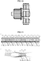
- FIG. 10 shows an example of an armature including a conventional commutator and rotor.
- Each commutator segment has a hook of a conductor. Normally, the conductor wire extending from a certain rotor winding (armature winding) of the rotor to the commutator is hooked on a hook of one commutator segment so as to be electrically conducting to electrically connect to another rotor winding (armature winding).
- armature winding rotor winding
- FIG. 11 shows a connection relation between the commutator and rotor disclosed as JP 63-146456 Y .
- Reference numerals 18-1 to 18-8 show each segment and reference numerals 20-1 to 20-24 show each slot.
- the conductor wire extending from each slot intersects many other conductor wires between the commutator and rotor.
- rotor windings wound between slots and conductor wires between the commutator and rotor are fixed around the rotation axis using an adhesive, for example, an epoxy adhesive.
- motors of the class of 500 W to 800 W have a smaller diameter of the commutator and a smaller diameter of the rotor core.
- the outside diameter of the commutator is 23.5 mm in an electric motor for high input of the class of input 1600 W to 2 kW
- the outside diameter of the commutator decreases to 20 to 21.5 mm in an electric motor for low input of the class of 500 to 800 W.
- the diameter of conductor wires extending from the commutator to the rotor and that of conductor wires of the rotor winding need to be necessarily made thinner.
- the present invention provides a new electric motor capable of preventing breakage of a conductor wire of a small diameter extending from the commutator to the rotor to be wound as a rotor winding (armature winding).
- the present invention provides a new electric motor capable of preventing breakage of a conductor wire used for an electric motor for vacuum cleaner of low input power, for example, an electric motor belonging to the class whose input is in the range of 500 to 800 W.
- the present invention provides an electric motor including a rotor fixed to a rotation axis and spread coaxially in a direction perpendicular to a direction of the rotation axis to be allowed to rotate around its axis, a commutator coaxially fixed to the rotation axis to come into sliding contact with a brush by rotating around its axis, and a stator arranged in a periphery of the rotor, wherein a felt is mounted on an end portion of the commutator on a side of the rotor and the felt holds at least partially a conductor wire that supplies a current from each segment to a corresponding winding of the rotor and also the felt and a portion of the conductor wire near or at the end of the commutator are fixed by a material with which the felt is impregnated and which solidifies when dried.
- Vibration of a conductor wire is interposed by using the felt as a vibration suppression member and an anchor effect is produced between the felt and a solidification material and between the solidification material and the conductor wire by the solidification material with which the felt is at least partially impregnated and which solidifies when dried and therefore, a vibration suppression effect thereof is further enhanced and a new effect of being able to prevent breakage of a conductor wire of a small diameter required for electric motors of low input power can be achieved.
- the present invention provides the electric motor in which a hole into which the rotation axis can be inserted is formed in a center portion of the felt and surroundings of the felt extend up to a vicinity of the commutator segment or to the commutator segment.
- varnish can be used as the material.
- the present invention provides the electric motor further including an insulating member in which a rotor side insulating portion providing electric insulation from the rotor and a tubular portion into which the rotation axis is inserted to provide insulation from surroundings are integrally formed, wherein the tubular portion extends up to a recess provided on the end of the commutator 30.
- the tubular portion extends up to the recess of the commutator and the tubular portion is formed integrally with the rotor side insulating portion and therefore, not only improvements of component strength and downsizing can be achieved, but also the felt can be arranged around the tubular portion to allow the felt to achieve a stable vibration absorption effect.
- the difference between vibration on the rotor side and vibration on the commutator side is mitigated and breakage of the conductor wire can further be prevented by the mitigated vibration being controlled by the felt.
- tubular portion preferably being partially fitted into the recess of the commutator, a similar vibration is generated as a whole and the generation of local vibration is considered to be further controlled.
- the number of segments of the commutator is 20 or more
- the number of slots of the rotor is 20 or more
- a diameter of the conductor wire is 0.35 mm or less. This is particularly effective for an electric motor in which the thickness of a conductor wire is extremely limited by an increased number of segments and the conductor wire is in danger of breakage.
- FIG. 1 is a schematic diagram of a motor driven fan 100 according to a first embodiment of the present invention.
- a fan casing unit 6 on one side and an electric motor casing 2 on the other side are integrated.
- a rotation axis (shaft) 4 axis-rotatably supported pivotally by a bearing 5, a commutator 30 and a rotor 10 fixed to the rotation axis 4 to rotate in accordance with the rotation of the rotation axis 4, and a stator 20 fixed inside the electric motor casing 2 like surrounding the rotor 10 are provided.
- an impeller 7 fixed to the rotation axis 4 to rotate is provided and an impeller casing 8 partially surrounding the impeller 7 is provided and an impeller 7 and an impeller casing 8 constitute the fan casing unit 6.
- FIG. 2 shows a motor driven rotator 1 to exercise a rotation drive force of an electric motor.
- the commutator 30 includes a plurality of conductors, for example, a plurality of commutator segments 31 made of copper (OFC).
- the plurality of commutator segments 31 is mounted on, for example, a commutator body made of resin in parallel with the axial direction of the rotation axis 4 thereof like spreading radially to the outer side in the radial direction.
- At least an outer surface of the commutator segment 31 is electrically exposed and a brush (not illustrated) is configured to be in sliding contact with the exposed surface.
- the brush is electrically connected to a field winding of the stator 20 described below.
- the basic configuration of the commutator segment 31 and the brush is known to people skilled in the art and so detailed description thereof is omitted here.
- the rotor 10 provided on the rotation axis 4 next to the commutator 30 has, as will be described in detail below, a plurality of slots formed thereon and conductor wires to be a plurality of the rotor windings 12 are wound around the plurality of slots.
- the plurality of rotor windings 12 and connection terminals of the commutator 30 are electrically coupled in an electromagnetic correspondence so that the electric motor is driven to rotate.
- FIG. 3 is a diagram that partially enlarges a portion between the commutator 30 and the rotor 10 arranged next to the commutator 30 of the motor driven rotator 1 in FIG. 2 .
- the commutator 30 having 22 segments and the rotor 10 having 22 slots are provided and the diameter of the rotor winding 12 and the conductor wire supplied from the commutator 30 to the rotor winding 12 is set to 0.35 mm or less, for example, between 0.2 to 0.35 mm.
- a protruding portion 33a protruding toward the side of the rotor 10 concentrically around the rotation axis (shaft) 4 is provided on an end of a commutator body 33 of the commutator 30 on the side of the rotor 10. Then, the felt 15 is mounted on an end face of the protruding portion 33a.
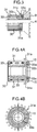
- FIG. 4A shows a sectional view of the commutator 30 on which the felt 15 is mounted and FIG. 4B shows a front view of the commutator 30 when viewed from the axial direction.
- the commutator 30 has an axial hole having a diameter so that the rotation axis (shaft) 4 passes therethrough and is fixed therein.
- the diameter of the axial hole is ⁇ 8.0 mm and the protruding portion 33a is formed by a recess portion 33b radially extending from the axial hole to have a diameter larger than that of the axial hole. Then, the protruding portion 33a has a surface facing the axial direction and spreading concentrically in the radial direction.
- FIG. 5A shows a front view when the felt 15 is viewed from the axial direction and FIG. 5B shows the side view of the felt 15.
- the felt 15 has a size enough to cover the spread surface of the protruding portion 33a and preferably has a hole of approximately the same diameter as that of the recess portion 33b in the center formed by the protruding portion 33a.
- the diameter of the recess portion 33b of the protruding portion 33a (that is, the inside diameter of the protruding portion) is ⁇ 10.8 mm and the inside diameter of the felt 15 is matched to this diameter and has ⁇ 10.8 mm.
- the surface of the protruding portion 33a (the surface facing the axial direction) preferably has a substantially flat portion and the height in the axial direction is somewhat smaller in the periphery thereof.
- the shape of the surface of the felt 15 is specified such that the felt 15 can be pasted along the surface of the protruding portion 33a.
- the felt 15 is elastically deformable and pasted to the surface of the protruding portion 33a using, for example, a double-faced tape or an adhesive so as to be along the surface of the substantially flat portion and a lower portion in the periphery of the commutator 30.
- the surface of one side of the double-faced tape may be pasted to the entire surface of one side of the felt 15 in advance.
- the felt 15 has a size to the extent that the protruding portion 33a of the commutator 30 is covered as a whole and preferably has a size to the extent that at least the periphery of the felt 15 reaches a hook 31a beyond an edge of the protruding portion 33a.
- the felt 15 can be pasted by being deformed in accordance with irregular changes of the surface of the protruding portion 33a and also, as will be described below, needs to support a conductor wire extending to the hook 31a of the commutator 30 from the rotor winding 12 and have flexibility and elasticity to the extent that vibration of the conductor wire can be absorbed. Therefore, the shape of the surface of the protruding portion 33a also preferably needs to have a size to the extent that such elasticity capable of absorbing vibration of the conductor wire is not hindered.
- the felt 15 is created by appropriately selecting a material having such flexibility and elasticity and in the present example, a felt made of a fiber blend of wool 80% and rayon 20% is used.
- a conductor wire extending from the hook 31a of the commutator 30 it is preferable to fix a conductor wire extending from the hook 31a of the commutator 30 to the felt using a fixative with which the felt 15 is impregnated in a liquid state and made of a material immobilized by drying.
- a fixative having such features, in addition to an effect of suppressing vibration by the felt itself as a vibration suppression member, an anchor effect between the felt and fixative and between the fixative and conductor wire also arises, further enhancing the vibration suppression effect.
- shaft insulators 9 mounted on the rotation axis (shaft) 4 like sandwiching the rotor core 11 from both sides are provided on the both sides of the rotor core 11 ( FIG. 7A ) constituting the rotor 10.
- FIG. 6A is a front view when the shaft insulator 9 is viewed from the axial direction and FIG. 6B is a side sectional view.
- the shaft insulator 9 can be made by molding an insulator material.
- the insulator material can be PET, but not limited to PET and it may be any material that has electric insulation properties, does less harm to human beings during processing, and can integrally be produced.
- the shaft insulator 9 has a tubular portion 9b having an axial hole of approximately the same diameter as that of the rotation axis 4 so that the rotation axis 4 can be inserted into and fixed to the axial hole and an expanding portion 9a expanding in the radial direction on one end of the tubular portion. If the rotation axis (shaft) 4 is made of a conductor, the tubular portion also has an electric insulation function from the rotation axis (shaft) 4. Also, the expanding portion 9a has an insulation function from the side face of the rotor core 11 described below.
- the two shaft insulators 9 are symmetrically arranged on both side faces of the rotor core 11 like sandwiching the rotor core 11 from both sides and fixed around the rotation axis (shaft) 4.
- an end of the tubular portion 9b thereof extends up to the recess portion 33b of the protruding portion 33a and the size of the recess portion 33b of the protruding portion 33a and the size of the outer shape of the tubular portion 9b are adjusted such that the end is at least partially received or at least partially fitted into the recess.
- the outside diameter of the tubular portion 9b has a diameter of approximately the same or less size so as to fit into the recess portion 33b.
- the tip of the tubular portion 9b may be formed in a tapering shape to at least partially fit into the recess portion 33b.
- the felt 15 is arranged around the tubular portion 9b. Also, the inside diameter of the felt 15 is matched to the diameter of the recess portion 33b of the protruding portion 33a, which is ⁇ 10.8 mm, and configured so that the tubular portion 9b can be inserted by fitting into the hole of the felt 15.
- FIG. 9 is a shape converted into a drawing of a state in which the felt 15 is actually used and a plurality of conductor wires leading to rotor windings is hooked on a plurality of the hooks 31a and wound around the axis by intersecting over the felt 15.
- One conductor wire is hooked on the hook 31a of one segment and intersected over the felt 15 to continue to a winding of different slots (not shown) of the rotor positioned in the right direction.
- the conductor wire is wound around the rotation axis (shaft) 4 by being throttled while intersecting other conductor wires over the felt 15 and so the felt 15 holds the conductor wire by being elastically deformed.
- the pressing force on the felt 15 from the conductor wire is applied in the direction of the rotation axis (shaft) 4 and the direction of the protruding portion 33a on the side face of the commutator 30 and the tubular portion 9b at least partially intrudes the recess portion 33b of the protruding portion 33a which is the side end of the commutator 30 and so the felt 15 is steadfastly supported by the protruding portion 33a and the tubular portion 9b and the conductor wire is reliably held by the felt 15.
- the protruding portion 33a and the tubular portion 9b simultaneously vibrate to make different vibrations less likely to arise in the conductor wire so that the possibility of breakage is reduced.
- the shaft insulator 9 is arranged integrally between the rotor core 11 and the commutator 30, the expanding portion 9a functions as a rotor side insulation portion, and the tubular portion 9b functions also as a rotation axis insulation portion and thus, the shaft insulator 9 assists the felt 15 to exert the vibration suppression effect and also exerts the insulation effect. Therefore, improvements of component strength and downsizing of a motor driven rotator demanded from electric motors of small power can be achieved and also a stable vibration absorption effect by the felt can be exerted.
- FIG. 7A is a front view when the rotor core 11 constituting the rotor 10 is viewed from the direction of the rotation axis 4.
- a plurality of slots 14 and a plurality of teeth 13 are alternately formed.
- an induced voltage (reactance voltage) generated during rectification by rotational movement of segments due to axis rotation, that is, when the brush separates from a coil and moves to the next coil, is reduced, thereby inhibiting sparking from occurring. Accordingly, abrasion of the brush that can be used for the commutator 30 smaller than in the past is also reduced so that the life of the electric motor itself can be prolonged.
- a thin flat rolled magnetic steel sheet and strip having predetermined electromagnetic characteristics and used also for the motor driven fan 100 for high input and high power to obtain high-speed rotation of 30,000 rpm(r/m) or more per minute developed in parallel with the present invention is made available.
- the bottom of the slot 14 is formed in a predetermined position in the radial direction from the axis center of the core at equal intervals in the circumferential direction. Accordingly, a plurality of the teeth 13 in the same substantial T shape in the radial direction when viewed from the axial direction and the slots 14 in the U shape between neighboring teeth are formed at equal intervals radially along the circumferential direction.
- the diameter A of the maximum outer circumference is set to about 35 mm
- the minimum distance B between slots opposite to each other among slots forming the plurality of teeth 13 is set to about 19.1 mm
- the diameter of the axial hole of the rotor core 11 is set to about 8 mm.
- the height of the teeth 13 specified by (A - B)/2 is about 7.95 mm and the height of the teeth 13 is set to at least 40% of the radius 17.5 mm of the rotor core.
- the height of the teeth 13 specified by (A - B)/2 is about 6.6 mm, which means that the height of the teeth 13 is at least 1/3 or more of the radius 19 mm of the rotor core, but in the embodiment of the present invention, the height of the teeth 13 has a larger ratio to the radius of the rotor core.
- An electric wire is wound around the plurality of teeth 13 by passing through the plurality of slots 14 extending in the axial direction like a coil and fixed using varnish to form the rotor core 11.
- the rotor core 11 of the electric motor can be produced by stacking a plurality of thin plate-like flat rolled magnetic steel sheets and strips in a layer structure. As described above, even in an environment in which a smaller winding diameter is required, a winding of extremely thin diameter is made unnecessary by allowing a relatively large number of slots for the rotor core 11 and the ratio of the length thereof to the rotor core diameter measured at the tip of teeth is made equal to a predetermined ratio or more so that a relatively wide region with respect to the region of the total diameter of the rotor core 11 is occupied by slots. However, the winding diameter is small when compared with the past and thus, as described above, it is necessary to reduce vibration affecting windings due to rotation of the motor driven rotator 1.
- the height of the teeth 13 has a large ratio and erosion by slots is significant and thus, it is necessary to efficiently obtain a large alternating field from a substantially decreased region of the rotor core. Therefore, it is necessary to achieve a high magnetic flux density quickly conforming to the alternating field and also to obtain enough motor characteristics by decreasing iron losses in accordance with frequency characteristics for the slots.
- iron losses include eddy current losses, hysteresis losses, and residual losses and typically eddy current losses and hysteresis losses.
- the thin flat rolled magnetic steel sheet and strip is provided with an insulating coating, for example, a chrome-free organic coating on the surface to suppress the generation of an eddy current by creating a thick multi-layer rotor core.
- an insulating coating for example, a chrome-free organic coating on the surface to suppress the generation of an eddy current by creating a thick multi-layer rotor core.
- iron losses of the thin flat rolled magnetic steel sheet and strip are set to 2.30 w/kg or less for W15/50 and 14.0 w/kg or less for W10/400 and magnetic flux density B50(T) is set to 1.62 or more.
- W15/50 is an iron loss when the frequency is 50 Hz and the maximum magnetic flux density is 1.5 Tesla
- W10/400 is an iron loss when the frequency is 400 Hz and the maximum magnetic flux density is 1.0 Tesla
- B50(T) shows the magnetic flux density at a magnetizing force of 5,000 A/m.
- the flat rolled magnetic steel sheet and strip specified in the present example is an extremely thin plate of 0.25 mm and thus, the rotor core easily can be formed into a smaller shape specific to the present example. Also, the weight of the rotor core itself is reduced and thus, damage done to mechanical portions due to vibration generated in accordance with rotation of the motor can be reduced.
- the thickness of a rotor core is increased, the amount of the flat rolled magnetic steel sheet and strip increases and efficiency is correspondingly improved, but external dimensions and the weight increase. In addition, the size thereof needs to be small enough to be usable in a vacuum cleaner.
- an electric motor that can be used for a vacuum cleaner and can achieve performance requirements demanded from a vacuum cleaner could be provided.
- FIG. 8A shows a stator core 21 when viewed from the axial direction of the electric motor and FIG. 8B is a side view of the stator core 21.
- the stator core 21 has two polar portions 23 facing each other and each is connected to a yoke 24 as a path of magnetic fluxes in the opposite position.
- the rotor core 11 is axis-rotatably arranged inside a space 26 formed between the polar portions 23 facing each other.
- Each of the polar portions 23 has a polar surface 23b in an arcuate shape corresponding to the tip surface of the teeth 13 of the rotor core 11 and a neck portion 25 connected so as to magnetically connect the yoke 24 and the polar surface 23b.
- Another space 27 is formed between the neck portion 25 and the yoke 24 on both sides of the polar portion 23 such that a field winding 22 (see FIG. 1 ) can sufficiently be wound around the neck portion 25 by passing through the space 27.
- the brush of the commutator 30 is electrically connected to the field winding of the stator 20.
- the yoke 24 has a substantially quadrangular strip shape so that an conductive wire can be wound many around the polar portion 23 up to the neck portion 25 and sides 23c have substantial straight lines such that an angle ⁇ formed by intersecting lines extending from the sides 23c specifying the space 27 on both sides of the polar portion 23 becomes a predetermined angle, for example, about 62 degrees.
- the length of the polar surface 23b of the polar portion 23 is set to a length to allow the eight teeth 13 of the rotor core 11 axis-rotatably mounted in the space 26 to be accommodated within the polar surface 23b so that a sufficient magnetic flux density is generated from the polar portion 23 to the yoke.
- the center portion of the polar portion 23 connected to the yoke 24 increases in the magnetic flux density when compared with a polar portion tip 23a of the polar portion 23.
- the width of the polar portion 23 is made to increase from the tip portion 23a of the polar portion 23 toward the center portion, thereby preventing a magnetic field line from becoming nonuniform.
- the maximum number of times of winding of a field winding that can be permitted increases with an increasing size of the space 27 and if the neck portion is small, the total length of the field winding used to wind as many times becomes shorter, which is effective in cost, makes the resistance due to field winding smaller, and reduces the weight.
- the angle ⁇ at which the lines extending from the sides 23c intersect is determined in consideration of making the space 27 large, the number of the teeth 13 in a magnetic interaction between the polar surface 23b of the polar portion 23 and the tip surface of the teeth 13 of the rotor core 11, and a tapering width of the polar portion 23 from the center portion of the polar portion 23 to the polar portion tip 23a to maintain the magnetic flux density constant as much as possible as the center of the polar portion 23 is approached and is preferably in the range of 60 to 64 degrees.
- the length of the stator core 21 in the axial direction is preferably substantially the same length of the rotor core 11 so as to have a magnetic interaction with the rotor core 11 in its entire length. Therefore, in the present example, the length of the stator core 21 is set to 21 mm to match 21 mm as the length of the rotor core 11 in the axial direction.
- the manufacturing and management can be made efficient by using the same material for the stator core as that of the rotor core and making basic iron loss characteristics the same as those of the rotor core.
- the stator core can be formed by stacking a plurality of layers of a stator core element made of a thin plate-like flat rolled magnetic steel sheet and strip and having the same shape and the same thickness and integrally combining such stator core elements.
- Each thin-plate stator core element constituting the stator core 21 and each thin-plate rotor core element constituting the rotor core 11 are each punched simultaneously in one press process using one mold so that the electromagnetic relationship of each thin flat rolled magnetic steel sheet and strip is correspondingly maintained.
- the stator core element has the same basic electromagnetic characteristics as those of the rotor core element, that is, based on the same measurements of JISC-2550 (2000), the stator core element is made of the thin flat rolled magnetic steel sheet and strip whose iron losses are set to 2.30 w/kg or less for W15/50 and 14.0 w/kg or less for W10/400 and whose magnetic flux density B50(T) is set to 1.62 or more.
- the rotor core element and stator core In the rotor core and stator core, a plurality of layers of the rotor core element or stator core element is fixed by caulking.
- the rotor core element and stator core element are an extremely thin flat rolled magnetic steel sheet and strip and thus, if fixed firmly by caulking, the insulating coating may be damaged and, as a result, an eddy current increases and a problem of increased flow losses may be caused.
- the plurality of layers of the rotor core element may be fixed by an adhesive.
- an insulating adhesive is preferably used for the adhesive, but if the influence of the eddy current generated by the adhesive itself is negligible, the adhesive may not necessarily be an insulating adhesive.
- stator core 21 is a portion of the stator and, when compared with the rotor core, is not driven to rotate and subjected to a force due to large acceleration and thus, all stator core elements may be combined and fixed by caulking.
- a recess 28 for caulking is provided at the four corners of the yoke in each rotor core element to allow fixing by caulking.
- the rotor core and the stator core are constructed by stacking 84 rotor core elements and 84 stator core elements respectively.
- An adhesive can be formed as a very thin layer and even if 84 elements are stacked and fixed using the adhesive, the influence on the total thickness of 21 mm does not practically arise.
Landscapes
- Engineering & Computer Science (AREA)
- Power Engineering (AREA)
- Motor Or Generator Current Collectors (AREA)
- Insulation, Fastening Of Motor, Generator Windings (AREA)
Applications Claiming Priority (1)
| Application Number | Priority Date | Filing Date | Title |
|---|---|---|---|
| JP2016158846A JP2018026984A (ja) | 2016-08-12 | 2016-08-12 | 電動機 |
Publications (2)
| Publication Number | Publication Date |
|---|---|
| EP3282567A2 true EP3282567A2 (fr) | 2018-02-14 |
| EP3282567A3 EP3282567A3 (fr) | 2018-03-07 |
Family
ID=59558295
Family Applications (1)
| Application Number | Title | Priority Date | Filing Date |
|---|---|---|---|
| EP17184991.2A Withdrawn EP3282567A3 (fr) | 2016-08-12 | 2017-08-04 | Moteur électrique |
Country Status (2)
| Country | Link |
|---|---|
| EP (1) | EP3282567A3 (fr) |
| JP (1) | JP2018026984A (fr) |
Cited By (1)
| Publication number | Priority date | Publication date | Assignee | Title |
|---|---|---|---|---|
| US11456649B2 (en) * | 2019-06-12 | 2022-09-27 | Aisin Corporation | Rotating electrical machine and manufacturing method thereof |
Citations (1)
| Publication number | Priority date | Publication date | Assignee | Title |
|---|---|---|---|---|
| JPS63146456U (fr) | 1987-03-17 | 1988-09-27 |
Family Cites Families (7)
| Publication number | Priority date | Publication date | Assignee | Title |
|---|---|---|---|---|
| NL6414564A (fr) * | 1964-12-15 | 1966-06-16 | ||
| US3519863A (en) * | 1969-01-02 | 1970-07-07 | Stanley Works | Commutator lead mounting |
| DE2536212A1 (de) * | 1975-08-13 | 1977-02-17 | Siemens Ag | Kommutatorlaeufer |
| JPS5785849U (fr) * | 1980-11-14 | 1982-05-27 | ||
| DE3631943A1 (de) * | 1986-09-19 | 1988-04-07 | Siemens Ag | Kommutatormotor mit isolierabdeckung der rotorwelle |
| DE19840149A1 (de) * | 1998-09-03 | 2000-03-16 | Atlas Copco Electric Tools | Läufer einer elektrischen Maschine |
| JP4726627B2 (ja) * | 2003-10-08 | 2011-07-20 | 株式会社ミツバ | 回転電機におけるアーマチュアおよびその製造方法 |
-
2016
- 2016-08-12 JP JP2016158846A patent/JP2018026984A/ja active Pending
-
2017
- 2017-08-04 EP EP17184991.2A patent/EP3282567A3/fr not_active Withdrawn
Patent Citations (1)
| Publication number | Priority date | Publication date | Assignee | Title |
|---|---|---|---|---|
| JPS63146456U (fr) | 1987-03-17 | 1988-09-27 |
Cited By (1)
| Publication number | Priority date | Publication date | Assignee | Title |
|---|---|---|---|---|
| US11456649B2 (en) * | 2019-06-12 | 2022-09-27 | Aisin Corporation | Rotating electrical machine and manufacturing method thereof |
Also Published As
| Publication number | Publication date |
|---|---|
| EP3282567A3 (fr) | 2018-03-07 |
| JP2018026984A (ja) | 2018-02-15 |
Similar Documents
| Publication | Publication Date | Title |
|---|---|---|
| JP5045909B2 (ja) | ラミネーション | |
| CN109104007B (zh) | 无刷电机及其定子 | |
| JP6220962B2 (ja) | アキシャルエアギャップ型回転電機 | |
| JP5409234B2 (ja) | 電動機 | |
| CN111245164B (zh) | 旋转电机及其制造方法 | |
| WO2014208110A1 (fr) | Machine électrique rotative de type axial | |
| JP2019083654A (ja) | 電動機およびターボ圧縮機 | |
| CN101689781B (zh) | 电动机的具有绝缘的定子和定子的绝缘以及电动工具机 | |
| JP5120801B2 (ja) | 回転機及び回転機を製造する方法 | |
| JP5693114B2 (ja) | Dcモータ | |
| KR20230115813A (ko) | 비접촉식 회전 변압기 및 이를 포함하는 모터 | |
| JP2014121210A (ja) | 軸流ファン | |
| CN205081606U (zh) | 马达以及离心送风机 | |
| CN108631473A (zh) | 电动机 | |
| EP3282567A2 (fr) | Moteur électrique | |
| KR101410491B1 (ko) | 전기자유닛 및 이를 구비한 회전기 | |
| JP4303579B2 (ja) | 三次元ステーター構造の回転機 | |
| EP2453551A2 (fr) | Stator d'un moteur de ventilation | |
| JPWO2014141656A1 (ja) | 電動機およびこの電動機を備えた電気機器 | |
| JP2010172096A (ja) | モータ | |
| CN102077445B (zh) | 电机 | |
| JP6988357B2 (ja) | 回転電機および回転電機の製造方法 | |
| KR20110064243A (ko) | 다각형 코일이 권선된 모터 | |
| JP2019030112A (ja) | モータ | |
| JP2018110505A (ja) | アキシャルギャップ型回転電機 |
Legal Events
| Date | Code | Title | Description |
|---|---|---|---|
| PUAI | Public reference made under article 153(3) epc to a published international application that has entered the european phase |
Free format text: ORIGINAL CODE: 0009012 |
|
| STAA | Information on the status of an ep patent application or granted ep patent |
Free format text: STATUS: THE APPLICATION HAS BEEN PUBLISHED |
|
| PUAL | Search report despatched |
Free format text: ORIGINAL CODE: 0009013 |
|
| AK | Designated contracting states |
Kind code of ref document: A2 Designated state(s): AL AT BE BG CH CY CZ DE DK EE ES FI FR GB GR HR HU IE IS IT LI LT LU LV MC MK MT NL NO PL PT RO RS SE SI SK SM TR |
|
| AX | Request for extension of the european patent |
Extension state: BA ME |
|
| AK | Designated contracting states |
Kind code of ref document: A3 Designated state(s): AL AT BE BG CH CY CZ DE DK EE ES FI FR GB GR HR HU IE IS IT LI LT LU LV MC MK MT NL NO PL PT RO RS SE SI SK SM TR |
|
| AX | Request for extension of the european patent |
Extension state: BA ME |
|
| RIC1 | Information provided on ipc code assigned before grant |
Ipc: H02K 23/00 20060101AFI20180126BHEP Ipc: H01R 39/32 20060101ALI20180126BHEP Ipc: H02K 13/04 20060101ALI20180126BHEP Ipc: H01R 39/16 20060101ALI20180126BHEP |
|
| STAA | Information on the status of an ep patent application or granted ep patent |
Free format text: STATUS: THE APPLICATION IS DEEMED TO BE WITHDRAWN |
|
| 18D | Application deemed to be withdrawn |
Effective date: 20180908 |