EP3282607B1 - Verfahren zur übertragung von interferenz-downlink-steuerinformationen in einem drahtloskommunikationssystem und vorrichtung dafür - Google Patents
Verfahren zur übertragung von interferenz-downlink-steuerinformationen in einem drahtloskommunikationssystem und vorrichtung dafür Download PDFInfo
- Publication number
- EP3282607B1 EP3282607B1 EP16776910.8A EP16776910A EP3282607B1 EP 3282607 B1 EP3282607 B1 EP 3282607B1 EP 16776910 A EP16776910 A EP 16776910A EP 3282607 B1 EP3282607 B1 EP 3282607B1
- Authority
- EP
- European Patent Office
- Prior art keywords
- control information
- downlink control
- interference
- information
- pdcch
- Prior art date
- Legal status (The legal status is an assumption and is not a legal conclusion. Google has not performed a legal analysis and makes no representation as to the accuracy of the status listed.)
- Active
Links
Images




Classifications
-
- H—ELECTRICITY
- H04—ELECTRIC COMMUNICATION TECHNIQUE
- H04W—WIRELESS COMMUNICATION NETWORKS
- H04W72/00—Local resource management
- H04W72/50—Allocation or scheduling criteria for wireless resources
- H04W72/54—Allocation or scheduling criteria for wireless resources based on quality criteria
- H04W72/541—Allocation or scheduling criteria for wireless resources based on quality criteria using the level of interference
-
- H—ELECTRICITY
- H04—ELECTRIC COMMUNICATION TECHNIQUE
- H04J—MULTIPLEX COMMUNICATION
- H04J11/00—Orthogonal multiplex systems, e.g. using WALSH codes
- H04J11/0023—Interference mitigation or co-ordination
- H04J11/005—Interference mitigation or co-ordination of intercell interference
-
- H—ELECTRICITY
- H04—ELECTRIC COMMUNICATION TECHNIQUE
- H04B—TRANSMISSION
- H04B7/00—Radio transmission systems, i.e. using radiation field
- H04B7/24—Radio transmission systems, i.e. using radiation field for communication between two or more posts
- H04B7/26—Radio transmission systems, i.e. using radiation field for communication between two or more posts at least one of which is mobile
-
- H—ELECTRICITY
- H04—ELECTRIC COMMUNICATION TECHNIQUE
- H04J—MULTIPLEX COMMUNICATION
- H04J11/00—Orthogonal multiplex systems, e.g. using WALSH codes
- H04J11/0023—Interference mitigation or co-ordination
-
- H—ELECTRICITY
- H04—ELECTRIC COMMUNICATION TECHNIQUE
- H04J—MULTIPLEX COMMUNICATION
- H04J11/00—Orthogonal multiplex systems, e.g. using WALSH codes
- H04J11/0023—Interference mitigation or co-ordination
- H04J11/0026—Interference mitigation or co-ordination of multi-user interference
-
- H—ELECTRICITY
- H04—ELECTRIC COMMUNICATION TECHNIQUE
- H04W—WIRELESS COMMUNICATION NETWORKS
- H04W72/00—Local resource management
- H04W72/04—Wireless resource allocation
- H04W72/044—Wireless resource allocation based on the type of the allocated resource
-
- H—ELECTRICITY
- H04—ELECTRIC COMMUNICATION TECHNIQUE
- H04W—WIRELESS COMMUNICATION NETWORKS
- H04W72/00—Local resource management
- H04W72/20—Control channels or signalling for resource management
- H04W72/23—Control channels or signalling for resource management in the downlink direction of a wireless link, i.e. towards a terminal
-
- H—ELECTRICITY
- H04—ELECTRIC COMMUNICATION TECHNIQUE
- H04W—WIRELESS COMMUNICATION NETWORKS
- H04W88/00—Devices specially adapted for wireless communication networks, e.g. terminals, base stations or access point devices
- H04W88/08—Access point devices
Definitions
- the present invention relates to a wireless communication system, and more particularly, to a method for receiving interference downlink control information in a wireless communication system and an apparatus therefor.
- M2M machine-to-machine
- PCs tablet personal computers
- CA carrier aggregation
- MIMO multiple antenna
- communication environments have evolved such that the density of accessible nodes is increased in the vicinity of a user equipment (UE).
- UE user equipment
- the node includes one or more antennas and refers to a fixed point capable of transmitting/receiving radio frequency (RF) signals to/from the user equipment (UE).
- RF radio frequency
- a communication system including high-density nodes may provide a communication service of higher performance to the UE by cooperation between nodes.
- a multi-node coordinated communication scheme in which a plurality of nodes communicates with a user equipment (UE) using the same time-frequency resources has much higher data throughput than legacy communication scheme in which each node operates as an independent base station (BS) to communicate with the UE without cooperation.
- BS base station
- a multi-node system performs coordinated communication using a plurality of nodes, each of which operates as a base station or an access point, an antenna, an antenna group, a remote radio head (RRH), and a remote radio unit (RRU).
- nodes are spaced apart from each other by a predetermined distance or more in the multi-node system.
- the nodes can be managed by one or more base stations or base station controllers which control operations of the nodes or schedule data transmitted/received through the nodes.
- Each node is connected to a base station or a base station controller which manages the node through a cable or a dedicated line.
- the multi-node system can be considered as a kind of Multiple Input Multiple Output (MIMO) system since dispersed nodes can communicate with a single UE or multiple UEs by simultaneously transmitting/receiving different data streams.
- MIMO Multiple Input Multiple Output
- the multi-node system transmits signals using the dispersed nodes, a transmission area covered by each antenna is reduced compared to antennas included in the conventional centralized antenna system. Accordingly, transmit power required for each antenna to transmit a signal in the multi-node system can be reduced compared to the conventional centralized antenna system using MIMO.
- a transmission distance between an antenna and a UE is reduced to decrease in pathloss and enable rapid data transmission in the multi-node system.
- the multi-node system reduces signal loss generated during transmission since base station(s) or base station controller(s) connected to a plurality of nodes transmit/receive data in cooperation with each other.
- base station(s) or base station controller(s) connected to a plurality of nodes transmit/receive data in cooperation with each other.
- nodes spaced apart by over a predetermined distance perform coordinated communication with a UE, correlation and interference between antennas are reduced. Therefore, a high signal to interference-plus-noise ratio (SINR) can be obtained according to the multi-node coordinated communication scheme.
- SINR signal to interference-plus-noise ratio
- the multi-node system is used with or replaces the conventional centralized antenna system to become a new foundation of cellular communication in order to reduce base station cost and backhaul network maintenance cost while extending service coverage and improving channel capacity and SINR in next-generation mobile communication systems.
- WO 2015/044408 A1 relates to a method, comprising determining transmission information for at least one interference source for a user equipment of a base station; and signaling the user equipment about the transmission information for the at least one interference source, wherein the transmission information is configured to facilitate a receiver of the user equipment to cancel interference from the at least one interference source.
- WO 2011/052869 A1 relates to a method of mitigating inter-cell interference in a wireless communication system, the method comprising receiving serving-cell data over a first data channel indicated by a first control channel for which decoding is successful by monitoring a plurality of candidate control channels in a search space of a serving cell; receiving interfering-cell data over a second data channel indicated by a second control channel for which decoding is successful by monitoring a plurality of candidate control channels in a search space of an interfering cell; and cancelling interference from the interfering cell by processing the serving-cell data and the interfering-cell data.
- US 2015/029958 A1 discloses a method for receiving, by a UE, information for interference cancellation, the method comprising receiving assistance control information for removing interference data from a neighboring eNB; and receiving primary control information indicating the interference data using the assistance control information, wherein the assistance control information includes at least one of control channel element (CCE) indices, an aggregation level and a downlink control information (DCI) format of a control channel on which the primary control information is transmitted and cyclic redundancy check (CRC) bits for the control channel, and wherein the assistance control information includes sub-assistance control information on neighboring UEs simultaneously scheduled by the neighboring eNB.
- CCE control channel element
- DCI downlink control information
- CRC cyclic redundancy check
- US 2015/009964 A1 discloses a method performed by an enhanced node B (eNB) in an LTE network for providing network assistance to user equipment (UE) for coordination of interference mitigation, the method comprising indicating a reduced a number of transmission options with a smaller signaling codebook, the smaller signaling codebook having entries that are a subset of entries of a larger master codebook; and providing network-assistance (NA) interference cancellation signaling (ICS) (NA-ICS) side information to the UE as part of a NA-ICS feedback message, the side information comprising indicators of the smaller signaling codebook, wherein the UE is arranged to perform an interference cancellation technique based on the smaller signaling codebook.
- eNB enhanced node B
- UE user equipment
- An object of the present invention is to suggest a method for efficiently supporting interference cancellation in a wireless communication system.
- the method may comprise receiving, from a base station, information on transmission modes or schemes of candidate interference downlink control information; receiving, from the base station, as the transmission mode or scheme of the interference downlink control information, information indicating one of the transmission modes or schemes of the candidate interference downlink control information, or a transmission mode or scheme which is the same as downlink control information for the terminal; and detecting interference downlink control information by searching for only the downlink control information of the indicated transmission mode or scheme of the interference downlink control information.
- the method may further comprise determining that the detected interference downlink control information is valid when a resource block allocation field of the detected interference downlink control information includes or is the same as a resource block allocation field of the downlink control information for the terminal.
- the method may further comprise determining that the detected interference downlink control information is valid if an interference Cell Radio Network Temporary Identity (C-RNTI) derived from bits corresponding to the detected interference downlink control information belongs to a candidate interference C-RNTI set received from the base station.
- C-RNTI Cell Radio Network Temporary Identity
- the method may further comprise the step of deriving interference Cell Radio Network Temporary Identity (C-RNTI) from bits corresponding to the detected interference downlink control information, wherein the derived interference C-RNTI may be used to acquire a scrambling code for interference downlink data information scheduled by the interference downlink control information.
- C-RNTI Cell Radio Network Temporary Identity
- the information indicating the transmission mode or scheme may be included in a specific field of the downlink control information for the terminal.
- the method may further comprise receiving information on an aggregation level or resource position of the interference downlink control information.
- the aggregation level of the interference downlink control information may be greater than an aggregation level of the downlink control information for the terminal.
- the method may further comprise reporting a capability of a maximum number of times of decoding the interference downlink control information of the terminal to the base station.
- a terminal having an interference cancellation capability, as defined in claim 8, configured to receive interference downlink control information in a wireless communication system comprises a radio frequency (RF) unit; and a processor controls the RF unit, wherein the processor may controls the RF unit to receive, from a base station, information on transmission modes or schemes of candidate interference downlink control information, controls the RF unit to receive, from the base station, as the transmission mode or scheme of the interference downlink control information, information indicating one of the transmission modes or schemes of the candidate interference downlink control information, or a transmission mode or scheme which is the same as downlink control information for the terminal, and detect interference downlink control information by searching for only the downlink control information of the indicated transmission mode or scheme of the interference downlink control information.
- RF radio frequency
- the processor may determine that the detected interference downlink control information is valid when a resource block allocation field of the detected interference downlink control information includes or is the same as a resource block allocation field of the downlink control information for the terminal.
- the processor may determine that the detected interference downlink control information is valid when an interference Cell Radio Network Temporary Identity (C-RNTI) derived from bits corresponding to the detected interference downlink control information belongs to a candidate interference C-RNTI set received from the base station.
- C-RNTI Cell Radio Network Temporary Identity
- the processor may be configured to derive interference Cell Radio Network Temporary Identity (C-RNTI) from bits corresponding to the detected interference downlink control information, and the derived interference C-RNTI is used to acquire a scrambling code for interference downlink data information scheduled by the interference downlink control information.
- C-RNTI Cell Radio Network Temporary Identity
- the information indicating the transmission mode or scheme may be included in a specific field of the downlink control information for the terminal.
- the processor may control to the RF unit to receive information on an aggregation level or resource position of the interference downlink control information.
- the aggregation level of the interference downlink control information may be greater than an aggregation level of the downlink control information for the terminal.
- the processor may report a capability of a maximum number of times of decoding the interference downlink control information of the terminal to the base station.
- interference cancellation may efficiently be performed in a wireless communication system.
- a user equipment is fixed or mobile.
- the UE is a device that transmits and receives user data and/or control information by communicating with a base station (BS).
- BS base station
- the term 'UE' may be replaced with 'terminal equipment', 'Mobile Station (MS)', 'Mobile Terminal (MT)', 'User Terminal (UT)', 'Subscriber Station (SS)', 'wireless device', 'Personal Digital Assistant (PDA)', 'wireless modem', 'handheld device', etc.
- a BS is typically a fixed station that communicates with a UE and/or another BS. The BS exchanges data and control information with a UE and another BS.
- BS may be replaced with 'Advanced Base Station (ABS)', 'Node B', 'evolved-Node B (eNB)', 'Base Transceiver System (BTS)', 'Access Point (AP)', 'Processing Server (PS)', etc.
- ABS Advanced Base Station
- eNB 'Node B'
- BTS Base Transceiver System
- AP Access Point
- PS Processing Server
- a node refers to a fixed point capable of transmitting/receiving a radio signal to/from a UE by communication with the UE.
- Various eNBs can be used as nodes.
- a node can be a BS, NB, eNB, pico-cell eNB
- a node may not be an eNB.
- a node can be a radio remote head (RRH) or a radio remote unit (RRU).
- the RRH and RRU have power levels lower than that of the eNB. Since the RRH or RRU (referred to as RRH/RRU hereinafter) is connected to an eNB through a dedicated line such as an optical cable in general, cooperative communication according to RRH/RRU and eNB can be smoothly performed compared to cooperative communication according to eNBs connected through a wireless link.
- At least one antenna is installed per node.
- An antenna may refer to an antenna port, a virtual antenna or an antenna group.
- a node may also be called a point.
- Unlink a conventional centralized antenna system (CAS) (i.e. single node system) in which antennas are concentrated in an eNB and controlled an eNB controller, plural nodes are spaced apart at a predetermined distance or longer in a multi-node system.
- the plural nodes can be managed by one or more eNBs or eNB controllers that control operations of the nodes or schedule data to be transmitted/received through the nodes.
- Each node may be connected to an eNB or eNB controller managing the corresponding node via a cable or a dedicated line.
- the same cell identity (ID) or different cell IDs may be used for signal transmission/reception through plural nodes.
- each of the plural nodes operates as an antenna group of a cell.
- the multi-node system can be regarded as a multi-cell (e.g. macro-cell/femto-cell/pico-cell) system.
- a network configured by multiple cells is called a multi-tier network.
- the cell ID of the RRH/RRU may be identical to or different from the cell ID of an eNB.
- the RRH/RRU and eNB use different cell IDs, both the RRH/RRU and eNB operate as independent eNBs.
- one or more eNBs or eNB controllers connected to plural nodes can control the plural nodes such that signals are simultaneously transmitted to or received from a UE through some or all nodes. While there is a difference between multi-node systems according to the nature of each node and implementation form of each node, multi-node systems are discriminated from single node systems (e.g. CAS, conventional MIMO systems, conventional relay systems, conventional repeater systems, etc.) since a plurality of nodes provides communication services to a UE in a predetermined time-frequency resource.
- single node systems e.g. CAS, conventional MIMO systems, conventional relay systems, conventional repeater systems, etc.
- a node refers to an antenna group spaced apart from another node by a predetermined distance or more, in general.
- embodiments of the present invention which will be described below, can even be applied to a case in which a node refers to an arbitrary antenna group irrespective of node interval.
- the embodiments of the preset invention are applicable on the assumption that the eNB controls a node composed of an H-pole antenna and a V-pole antenna.
- a communication scheme through which signals are transmitted/received via plural transmit (Tx)/receive (Rx) nodes, signals are transmitted/received via at least one node selected from plural Tx/Rx nodes, or a node transmitting a downlink signal is discriminated from a node transmitting an uplink signal is called multi-eNB MIMO or CoMP (Coordinated Multi-Point Tx/Rx).
- CoMP Coordinated Multi-Point Tx/Rx.
- Coordinated transmission schemes from among CoMP communication schemes can be categorized into JP (Joint Processing) and scheduling coordination.
- the former may be divided into JT (Joint Transmission)/JR (Joint Reception) and DPS (Dynamic Point Selection) and the latter may be divided into CS (Coordinated Scheduling) and CB (Coordinated Beamforming). DPS may be called DCS (Dynamic Cell Selection).
- JP Joint Transmission
- JR Joint Reception
- DCS Coordinatd Beamforming
- DPS refers to a communication scheme by which a signal is transmitted/received through a node selected from plural nodes according to a specific rule.
- signal transmission reliability can be improved because a node having a good channel state between the node and a UE is selected as a communication node.
- a cell refers to a specific geographical area in which one or more nodes provide communication services. Accordingly, communication with a specific cell may mean communication with an eNB or a node providing communication services to the specific cell.
- a downlink/uplink signal of a specific cell refers to a downlink/uplink signal from/to an eNB or a node providing communication services to the specific cell.
- a cell providing uplink/downlink communication services to a UE is called a serving cell.
- channel status/quality of a specific cell refers to channel status/quality of a channel or a communication link generated between an eNB or a node providing communication services to the specific cell and a UE.
- a UE can measure downlink channel state from a specific node using one or more CSI-RSs (Channel State Information Reference Signals) transmitted through antenna port(s) of the specific node on a CSI-RS resource allocated to the specific node.
- CSI-RSs Channel State Information Reference Signals
- neighboring nodes transmit CSI-RS resources on orthogonal CSI-RS resources.
- CSI-RS resources are orthogonal, this means that the CSI-RS resources have different subframe configurations and/or CSI-RS sequences which specify subframes to which CSI-RSs are allocated according to CSI-RS resource configurations, subframe offsets and transmission periods, etc. which specify symbols and subcarriers carrying the CSI RSs.
- PDCCH Physical Downlink Control Channel
- PCFICH Physical Control Format Indicator Channel
- PHICH Physical Hybrid automatic repeat request Indicator Channel
- PDSCH Physical Downlink Shared Channel
- PUCCH Physical Uplink Control Channel
- PUSCH Physical Uplink Shared Channel
- PRACH Physical Random Access Channel
- a time-frequency resource or a resource element (RE) which is allocated to or belongs to PDCCH/PCFICH/PHICH/PDSCH/PUCCH/PUSCH/PRACH, is referred to as a PDCCH/PCFICH/PHICH/PDSCH/PUCCH/PUSCH/PRACH RE or PDCCH/PCFICH/PHICH/PDSCH/PUCCH/PUSCH/PRACH resource.
- transmission of PUCCH/PUSCH/PRACH by a UE is equivalent to transmission of uplink control information/uplink data/random access signal through or on PUCCH/PUSCH/PRACH.
- transmission of PDCCH/PCFICH/PHICH/PDSCH by an eNB is equivalent to transmission of downlink data/control information through or on PDCCH/PCFICH/PHICH/PDSCH.
- FIG. 1 illustrates an exemplary radio frame structure used in a wireless communication system.
- FIG. 1(a) illustrates a frame structure for frequency division duplex (FDD) used in 3GPP LTE/LTE-A and
- FIG. 1(b) illustrates a frame structure for time division duplex (TDD) used in 3GPP LTE/LTE-A.
- FDD frequency division duplex
- TDD time division duplex
- a radio frame used in 3GPP LTE/LTE-A has a length of 10ms (307200Ts) and includes 10 subframes in equal size.
- the 10 subframes in the radio frame may be numbered.
- Each subframe has a length of 1ms and includes two slots.
- 20 slots in the radio frame can be sequentially numbered from 0 to 19.
- Each slot has a length of 0.5ms.
- a time for transmitting a subframe is defined as a transmission time interval (TTI).
- Time resources can be discriminated by a radio frame number (or radio frame index), subframe number (or subframe index) and a slot number (or slot index).
- the radio frame can be configured differently according to duplex mode. Downlink transmission is discriminated from uplink transmission by frequency in FDD mode, and thus the radio frame includes only one of a downlink subframe and an uplink subframe in a specific frequency band. In TDD mode, downlink transmission is discriminated from uplink transmission by time, and thus the radio frame includes both a downlink subframe and an uplink subframe in a specific frequency band.
- Table 1 shows DL-UL configurations of subframes in a radio frame in the TDD mode.
- D L-UL configuration Downlink -to-Uplink Switch-point periodicity Subframe number 0 1 2 3 4 5 6 7 8 9 0 5ms D S U U U D S U U U 1 5ms D S U U D D S U U D 2 5ms D S U D D D S U D D 3 10ms D S U U U D D D D D D 4 10ms D S U U D D D D D D 5 10ms D S U D D D D D D D 6 5ms D S U U U U D S U U D S U U D
- D denotes a downlink subframe
- U denotes an uplink subframe
- S denotes a special subframe.
- the special subframe includes three fields of DwPTS (Downlink Pilot TimeSlot), GP (Guard Period), and UpPTS (Uplink Pilot TimeSlot).
- DwPTS is a period reserved for downlink transmission
- UpPTS is a period reserved for uplink transmission.
- Table 2 shows special subframe configuration.
- FIG. 2 illustrates an exemplary downlink/uplink slot structure in a wireless communication system. Particularly, FIG. 2 illustrates a resource grid structure in 3GPP LTE/LTE-A. A resource grid is present per antenna port.
- a slot includes a plurality of OFDM (Orthogonal Frequency Division Multiplexing) symbols in the time domain and a plurality of resource blocks (RBs) in the frequency domain.
- An OFDM symbol may refer to a symbol period.
- a signal transmitted in each slot may be represented by a resource grid composed of N RB DL / UL ⁇ N sc RB subcarriers and N symb DL / UL OFDM symbols.
- N RB DL denotes the number of RBs in a downlink slot
- N RB UL denotes the number of RBs in an uplink slot.
- N RB DL and N RB UL respectively depend on a DL transmission bandwidth and a UL transmission bandwidth.
- N symb DL denotes the number of OFDM symbols in the downlink slot and N symb UL denotes the number of OFDM symbols in the uplink slot.
- N sc RB denotes the number of subcarriers constructing one RB.
- An OFDM symbol may be called an SC-FDM (Single Carrier Frequency Division Multiplexing) symbol according to multiple access scheme.
- the number of OFDM symbols included in a slot may depend on a channel bandwidth and the length of a cyclic prefix (CP).
- CP cyclic prefix
- a slot includes 7 OFDM symbols in the case of normal CP and 6 OFDM symbols in the case of extended CP.
- FIG. 2 illustrates a subframe in which a slot includes 7 OFDM symbols for convenience, embodiments of the present invention can be equally applied to subframes having different numbers of OFDM symbols.
- each OFDM symbol includes N RB DL / UL ⁇ N sc RB subcarriers in the frequency domain.
- Subcarrier types can be classified into a data subcarrier for data transmission, a reference signal subcarrier for reference signal transmission, and null subcarriers for a guard band and a direct current (DC) component.
- the null subcarrier for a DC component is a subcarrier remaining unused and is mapped to a carrier frequency (f0) during OFDM signal generation or frequency up-conversion.
- the carrier frequency is also called a center frequency.
- An RB is defined by N symb DL / UL (e.g. 7) consecutive OFDM symbols in the time domain and N sc RB (e.g. 12) consecutive subcarriers in the frequency domain.
- N symb DL / UL e.g. 7
- N sc RB e.g. 12
- a resource composed by an OFDM symbol and a subcarrier is called a resource element (RE) or a tone.
- an RB is composed of N symb DL / UL ⁇ N sc RB REs.
- Each RE in a resource grid can be uniquely defined by an index pair (k, 1) in a slot.
- k is an index in the range of 0 to N symb DL / UL ⁇ N sc RB ⁇ 1 in the frequency domain and 1 is an index in the range of 0 to N symb DL / UL ⁇ 1 .
- Two RBs that occupy N sc RB consecutive subcarriers in a subframe and respectively disposed in two slots of the subframe are called a physical resource block (PRB) pair.
- Two RBs constituting a PRB pair have the same PRB number (or PRB index).
- FIG. 3 illustrates a downlink (DL) subframe structure used in 3GPP LTE/LTE-A.
- a DL subframe is divided into a control region and a data region.
- a maximum of three (four) OFDM symbols located in a front portion of a first slot within a subframe correspond to the control region to which a control channel is allocated.
- a resource region available for PDCCH transmission in the DL subframe is referred to as a PDCCH region hereinafter.
- the remaining OFDM symbols correspond to the data region to which a physical downlink shared chancel (PDSCH) is allocated.
- PDSCH physical downlink shared chancel
- a resource region available for PDSCH transmission in the DL subframe is referred to as a PDSCH region hereinafter.
- Examples of downlink control channels used in 3GPP LTE include a physical control format indicator channel (PCFICH), a physical downlink control channel (PDCCH), a physical hybrid ARQ indicator channel (PHICH), etc.
- the PCFICH is transmitted at a first OFDM symbol of a subframe and carries information regarding the number of OFDM symbols used for transmission of control channels within the subframe.
- the PHICH is a response of uplink transmission and carries an HARQ acknowledgment (ACK)/negative acknowledgment (NACK) signal.
- ACK HARQ acknowledgment
- NACK negative acknowledgment
- the DCI contains resource allocation information and control information for a UE or a UE group.
- the DCI includes a transport format and resource allocation information of a downlink shared channel (DL-SCH), a transport format and resource allocation information of an uplink shared channel (UL-SCH), paging information of a paging channel (PCH), system information on the DL-SCH, information about resource allocation of an upper layer control message such as a random access response transmitted on the PDSCH, a transmit control command set with respect to individual UEs in a UE group, a transmit power control command, information on activation of a voice over IP (VoIP), downlink assignment index (DAI), etc.
- DL-SCH downlink shared channel
- UL-SCH uplink shared channel
- PCH paging information of a paging channel
- system information on the DL-SCH information about resource allocation of an upper layer control message such as a random access response transmitted on the PDSCH
- the transport format and resource allocation information of the DL-SCH are also called DL scheduling information or a DL grant and the transport format and resource allocation information of the UL-SCH are also called UL scheduling information or a UL grant.
- the size and purpose of DCI carried on a PDCCH depend on DCI format and the size thereof may be varied according to coding rate.
- Control information such as a hopping flag, information on RB allocation, modulation coding scheme (MCS), redundancy version (RV), new data indicator (NDI), information on transmit power control (TPC), cyclic shift demodulation reference signal (DMRS), UL index, channel quality information (CQI) request, DL assignment index, HARQ process number, transmitted precoding matrix indicator (TPMI), precoding matrix indicator (PMI), etc. is selected and combined based on DCI format and transmitted to a UE as DCI.
- MCS modulation coding scheme
- RV redundancy version
- NDI new data indicator
- TPC transmit power control
- DMRS cyclic shift demodulation reference signal
- CQI channel quality information
- TPMI transmitted precoding matrix indicator
- PMI precoding matrix indicator
- a DCI format for a UE depends on transmission mode (TM) set for the UE.
- TM transmission mode
- only a DCI format corresponding to a specific TM can be used for a UE configured in the specific TM.
- a PDCCH is transmitted on an aggregation of one or several consecutive control channel elements (CCEs).
- the CCE is a logical allocation unit used to provide the PDCCH with a coding rate based on a state of a radio channel.
- the CCE corresponds to a plurality of resource element groups (REGs). For example, a CCE corresponds to 9 REGs and an REG corresponds to 4 REs.
- 3GPP LTE defines a CCE set in which a PDCCH can be located for each UE.
- a CCE set from which a UE can detect a PDCCH thereof is called a PDCCH search space, simply, search space.
- An individual resource through which the PDCCH can be transmitted within the search space is called a PDCCH candidate.
- a set of PDCCH candidates to be monitored by the UE is defined as the search space.
- search spaces for DCI formats may have different sizes and include a dedicated search space and a common search space.
- the dedicated search space is a UE-specific search space and is configured for each UE.
- the common search space is configured for a plurality of UEs.
- Aggregation levels defining the search space is as follows. [Table3] Search Space Number of PDCCH candidates M (L) Type Aggregation Level L Size [in CCEs] UE-specific 1 6 6 2 12 6 4 8 2 8 16 2 Common 4 16 4 8 16 2
- a PDCCH candidate corresponds to 1, 2, 4 or 8 CCEs according to CCE aggregation level.
- An eNB transmits a PDCCH (DCI) on an arbitrary PDCCH candidate with in a search space and a UE monitors the search space to detect the PDCCH (DCI).
- monitoring refers to attempting to decode each PDCCH in the corresponding search space according to all monitored DCI formats.
- the UE can detect the PDCCH thereof by monitoring plural PDCCHs. Since the UE does not know the position in which the PDCCH thereof is transmitted, the UE attempts to decode all PDCCHs of the corresponding DCI format for each subframe until a PDCCH having the ID thereof is detected. This process is called blind detection (or blind decoding (BD)).
- BD blind decoding
- the eNB can transmit data for a UE or a UE group through the data region.
- Data transmitted through the data region may be called user data.
- a physical downlink shared channel (PDSCH) may be allocated to the data region.
- a paging channel (PCH) and downlink-shared channel (DL-SCH) are transmitted through the PDSCH.
- the UE can read data transmitted through the PDSCH by decoding control information transmitted through a PDCCH.
- Information representing a UE or a UE group to which data on the PDSCH is transmitted, how the UE or UE group receives and decodes the PDSCH data, etc. is included in the PDCCH and transmitted.
- a specific PDCCH is CRC (cyclic redundancy check)-masked having radio network temporary identify (RNTI) of "A" and information about data transmitted using a radio resource (e.g. frequency position) of "B” and transmission format information (e.g. transport block size, modulation scheme, coding information, etc.) of "C" is transmitted through a specific DL subframe
- the UE monitors PDCCHs using RNTI information and a UE having the RNTI of "A” detects a PDCCH and receives a PDSCH indicated by "B” and "C” using information about the PDCCH.
- a reference signal (RS) to be compared with a data signal is necessary for the UE to demodulate a signal received from the eNB.
- a reference signal refers to a predetermined signal having a specific waveform, which is transmitted from the eNB to the UE or from the UE to the eNB and known to both the eNB and UE.
- the reference signal is also called a pilot.
- Reference signals are categorized into a cell-specific RS shared by all UEs in a cell and a modulation RS (DM RS) dedicated for a specific UE.
- DM RS modulation RS
- a DM RS transmitted by the eNB for demodulation of downlink data for a specific UE is called a UE-specific RS.
- Both or one of DM RS and CRS may be transmitted on downlink.
- an RS for channel measurement needs to be additionally provided because the DM RS transmitted using the same precoder as used for data can be used for demodulation only.
- CSI-RS corresponding to an additional RS for measurement is transmitted to the UE such that the UE can measure channel state information.
- CSI-RS is transmitted in each transmission period corresponding to a plurality of subframes based on the fact that channel state variation with time is not large, unlike CRS transmitted per subframe.
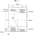
- FIG. 4 illustrates an exemplary uplink subframe structure used in 3GPP LTE/LTE-A.
- a UL subframe can be divided into a control region and a data region in the frequency domain.
- One or more PUCCHs (physical uplink control channels) can be allocated to the control region to carry uplink control information (UCI).
- One or more PUSCHs (Physical uplink shared channels) may be allocated to the data region of the UL subframe to carry user data.
- subcarriers spaced apart from a DC subcarrier are used as the control region.
- subcarriers corresponding to both ends of a UL transmission bandwidth are assigned to UCI transmission.
- the DC subcarrier is a component remaining unused for signal transmission and is mapped to the carrier frequency f0 during frequency up-conversion.
- a PUCCH for a UE is allocated to an RB pair belonging to resources operating at a carrier frequency and RBs belonging to the RB pair occupy different subcarriers in two slots. Assignment of the PUCCH in this manner is represented as frequency hopping of an RB pair allocated to the PUCCH at a slot boundary. When frequency hopping is not applied, the RB pair occupies the same subcarrier.
- the PUCCH can be used to transmit the following control information.
- the quantity of control information (UCI) that a UE can transmit through a subframe depends on the number of SC-FDMA symbols available for control information transmission.
- the SC-FDMA symbols available for control information transmission correspond to SC-FDMA symbols other than SC-FDMA symbols of the subframe, which are used for reference signal transmission.
- SRS sounding reference signal
- the last SC-FDMA symbol of the subframe is excluded from the SC-FDMA symbols available for control information transmission.
- a reference signal is used to detect coherence of the PUCCH.
- the PUCCH supports various formats according to information transmitted thereon.
- Table 4 shows the mapping relationship between PUCCH formats and UCI in LTE/LTE-A.
- PUCCH format Modulation scheme Number of bits per subframe, M bit Usage Etc. 1 N/A N/A SR (Scheduling Request) 1a BPSK 1 ACK/NACK or SR + ACK/NACK One codeword 1b QPSK 2 ACK/NACK or SR + ACK/NACK Two codeword 2 QPSK 20 CQI/PMI/RI Joint ACK/NACK (extended CP) 2a QPSK+BPSK 21 CQI/PMI/RI + ACK/NACK Normal CP only 2b QPSK+QPSK 22 CQI/PMI/RI + ACK/NACK Normal CP only 3 QPSK 48 ACK/NACK or SR + ACK/NACK or CQI/PMI/RI + ACK/NACK
- PUCCH formats 1/1a/1b are used to transmit ACK/NACK information
- PUCCH format 2/2a/2b are used to carry CSI such as CQI/PMI/RI
- PUCCH format 3 is used to transmit ACK/NACK information.
- CoMP Coordinated multi-point
- CoMP transmission/reception technlogy may increase performance of a UE located at a cell edge and increase average sector throughput.
- ICI inter-cell interference
- FFR fractional frequency reuse
- the CoMP scheme applicable to downlink may be largely divided into a joint processing (JP) scheme and a coordinated scheduling/beamforming (CS/CB) scheme.
- JP joint processing
- CS/CB coordinated scheduling/beamforming
- each point (BS) of a CoMP unit may use data.
- the CoMP unit refers to a set of BSs used in the CoMP scheme.
- the JP scheme may be classified into a joint transmission scheme and a dynamic cell selection scheme.
- the joint transmission scheme refers to a scheme for simultaneously transmitting a PDSCH from a plurality of points (a part or the whole of the CoMP unit). That is, data transmitted to a single UE may be simultaneously transmitted from a plurality of transmission points. According to the joint transmission scheme, it is possible to coherently or non-coherently improve the quality of the received signals and to actively cancel interference with another UE.
- the dynamic cell selection scheme refers to a scheme for transmitting a PDSCH from one point (of the CoMP unit). That is, data transmitted to a single UE at a specific time is transmitted from one point and the other points in the coordinated unit do not transmit data to the UE at that time.
- the point for transmitting the data to the UE may be dynamically selected.
- the CoMP units may cooperatively perform beamforming of data transmission to a single UE. Although only a serving cell transmits the data, user scheduling/beamforming may be determined by the coordination of the cells of the CoMP unit.
- coordinated multi-point reception refers to reception of a signal transmitted by coordination among a plurality of geographically separated points.
- CoMP schemes applicable to uplink may be classified into Joint Reception (JR) and Coordinated Scheduling/Beamforming (CS/CB).
- JR indicates that a plurality of reception points receives a signal transmitted through a PUSCH
- the CS/CB scheme indicates that only one point receives a PUSCH
- user scheduling/beamforming is determined by the coordination of the cells of the CoMP unit.
- a plurality of UL points (that is, receiving points (RPs)) is referred to as UL CoMP and a plurality of DL points (that is, transmitting points (TPs)) is referred to as DL CoMP.
- the present invention relates to transferring, to a advanced receiver (AR) UE, a scheduling information of an interfering PDSCH being scheduled together with a desired PDSCH to assist interference cancellation (IC) capabilities of the advanced receiver.
- AR advanced receiver
- IC interference cancellation
- a cellular mobile communication system is an interference-limited system due to inter-cell interference in an urban environment and reaches system capacity limit.
- a MIMO scheme that is, an SU-MIMO scheme or a MU-MIMO scheme
- one eNB transmits a multi-layer signal of multiple beams
- inter-layer interference in a cell is also a main factor for deciding system capacity limit. Therefore, in order to reduce inter-cell interference and intra-cell interference, standardization and development of a coordinated transmission and high-performance receiver scheme becomes important and numerous effects in that direction have been made.
- a downlink CoMP scheme configures transmission beams such that inter-cell interference and intra-cell interference are minimized in a transmitter based on channel state information received from a receiver.
- complexity of the UE in a data reception process is not increased, but performance of the CoMP scheme largely depends on accuracy of a channel state information report.
- the high-performance receiver scheme obtains better reception performance using properties of an interference signal at a receiver.
- how the UE acquires information on the interference signal transmitted along with a signal (that is, a desired signal) scheduled thereto becomes important.
- Representative examples of the high-performance receiver scheme may include:
- a certain level of detection capability is needed to cancel an interference signal. That is, an interference signal may be stably canceled when an interference packet is successfully decoded or when hard decision error probability of a coding symbol of an interference packet is less than a specific value. Accordingly, a modulation and coding scheme (MCS) of an interference signal should be determined in such a manner that an interfered device can stably receive the interference signal. That is, the MCS of each transmission signal should be determined in such a manner that both a UE scheduled to receive a corresponding DL signal and an interfered UE can stably receive the DL signal.
- MCS modulation and coding scheme
- an eNB transmits information required to decode a PDSCH, which corresponds to a desired signal, to a UE using DCI of a PDCCH.
- the PDCCH is transmitted by including CRC parity bits to detect an error.
- the CRC parity bits are transmitted after being scrambled with a cell-RNTI (C-RNTI) allocated to the UE.
- C-RNTI cell-RNTI
- the UE performs PDCCH decoding (i.e., blind decoding) a plurality of times on a PDCCH search space given to the UE, and determines that DCI in a corresponding PDCCH has PDSCH scheduling information (e.g., DL grant or UL grant) to be transmitted to the UE, if the decoded CRC parity bits has the C-RNTI allocated to the UE.
- PDCCH decoding i.e., blind decoding
- a SU-MIMO transmission scheme of the LTE system when two or more layers are transmitted, two transport blocks (TBs) are transmitted to apply inter-layer interference cancellation. If one of the two TBs is successfully decoded, the UE regenerates a transmission signal of the corresponding TB, takes it out from a reception signal, and decodes the other TB again in an environment where inter-layer interference is cancelled.
- DCI of SU-MIMO has MCS information, a new data indicator (NDI), and a redundancy version (RV) for each of TB1 and TB2.
- FIG. 5 shows an example of the configuration of PDCCH in the LTE(-A) system.
- Information delivered on the PDCCH mainly includes DCI and CRC parity bits masked with a C-RNTI.
- FIG. 5 shows an example of DCI of SU-MIMO.
- the DCI includes a resource allocation (RA) field, HARQ process field, transmit power control (TPC) field, layer mapping information (LMI) field, and fields for transmitting MCS, NDI, and RV information of each TB.
- RA resource allocation
- TPC transmit power control
- LMI layer mapping information
- Scheduling information of a plurality of PDSCHs co-scheduled in the same time-frequency resource in an LTE system is delivered through individual PDCCH. That is, if PDSCH1 transmitted to UE1 and PDSCH2 transmitted to UE2 are co-scheduled in the same resource, PDCCH1 that includes scheduling information of PDSCH1 is masked with C-RNTI1 allocated to UE1 and then transmitted to UE1 from a PDCCH space determined by C-RNTI1, and PDCCH2 that includes scheduling information of PDSCH2 is masked with C-RNTI2 allocated to UE2 and then transmitted to UE2 from a PDCCH space determined by C-RNTI2. Therefore, in order that UE1 which is an advanced receiver (AR) UE discovers scheduling information of co-scheduled interfering PDSCHs without additional PDCCH overhead, an overhearing method of PDCCH2 transmitted to UE2 may be considered.
- AR advanced receiver
- PDSCH1 will be referred to as desired PDSCH
- PDCCH1 will be referred to as desired PDCCH
- PDSCH2 will be referred to as an interfering PDSCH
- PDCCH2 will be referred to as an interfering PDCCH
- DCI delivered through PDCCH2 will be referred to as interfering DCI.
- the AR UE should perform decoding for all PDCCH transmission spaces in accordance with various DCI formats.
- the AR UE since the AR UE cannot know C-RNTI allocated to a UE targeted by each DCI, the AR UE disregards error detection based on CRC and determines how resource allocation of DCI is matched with resource allocation of desired PDCSH, whereby interfering PDSCHs which are likely to cancel interference are only subjected to decoding.
- the number of PDCCH blind decoding times is remarkably increased, whereby a problem occurs in throughput degradation according to increase of the probability of false alarm and complexity of UE are increased.
- the number of OFDM symbols used for PDCCH in the LTE system is designated per subframe through PCFICH (physical control format indicator channel). That is, a size of a resource region to which PDCCH is transmitted may be varied per subframe.
- the number of REs used for PDCCH in a bandwidth system of 20MHz is indicated as listed in Table 5 depending on the number of OFDM symbols used for PDCCH. In this case, it is assumed that 1 or 2 port CRS transmission is performed and three PHICH groups are allocated for PHICH. Also, a maximum number of control channel elements (CCEs) are determined depending on the number of OFDM symbols used for PDCCH in Table 5.
- CCEs control channel elements
- REs of a control channel region are defined as a resource element group (REG) in such a manner that the other REs except RE for CRS transmission are grouped in a unit of 4 continuous REs.
- REG resource element group
- 9 REGs interleaved except REGs used for PCFICH and PHICH transmission are grouped to form CCE.
- CCE correspond to 36 REs.
- Table 7 illustrates a space of a PDCCH region, from which DCI format and corresponding DCI according to a PDSCH transmission mode (TM) are transmitted. Also, in each transmission mode of Table 7, a PDSCH transmission mode when scheduling is performed by TM independent DCI and a PDSCH transmission mode when scheduling is performed by TM dependent DCI are listed in the last column.
- TM PDSCH transmission mode
- Transmission mode DCI format Search space PDSCH transmission mode corresponding to PDCCH Mode 1 DCI format 1A Common and UE-specific by C-RNTI Single-antenna port, port 0 DCI format 1 UE-specific by C-RNTI Single-antenna port, port 0 Mode 2 DCI format 1A Common and UE-specific by C-RNTI Transmission diversity DCI format 1 UE-specific by C-RNTI Transmission diversity Mode 3 DCI format 1A Common and UE-specific by C-RNTI Transmission diversity DCI format 2A UE-specific by C-RNTI Large delay CDD or transmission diversity Mode 4 DCI format 1A Common and UE-specific by C-RNTI Transmission diversity DCI format 2 UE-specific by C-RNTI Closed-loop spatial multiplexing or transmission diversity Mode 5 DCI format 1A Common and UE-specific by C-RNTI Transmission diversity DCI format 1D UE-specific by C-RNTI Multi-user MIMO Mode 6 DCI format 1A Common and UE-specific by C-RNTI Transmission diversity
- DCI format 1 UE-specific by C-RNTI Single-antenna port, port 5 Mode 8 DCI format 1A Common and UE-specific by C-RNTI If the number of PBCH antenna ports is one, single antenna port, port 0 is used, and if not so, transmission diversity is used.
- - MBSFN subframe single-antenna port, port 7 DCI format 2C UE-specific by C-RNTI Up to transmission of 8 layers, ports 7 to 14 or single-antenna port, port 7 or 8 Mode 10 DCI format 1A
- Common and UE-specific by C-RNTI -Non-MBSFN subframe If the number of PBCH antenna ports is one, single antenna port, port 0 is used, and if not so, transmission diversity is used.
- - MBSFN subframe single-antenna port, port 7 DCI format 2D UE-specific by C-RNTI Up to transmission of 8 layers, ports 7 to 14 or single-antenna port, port 7 or 8
- a size of DCI that is, the number of bits is varied depending on DCI format. Therefore, if transmission modes of co-scheduled interfering PDSCHs are not notified to the AR UE previously, the AR UE should perform decoding to be matched with a size of all DCI formats available from each PDCCH transmission resource candidate.
- DCI for PDSCH scheduling of each transmission mode may be transmitted by either DCI format 1A which is TM independent DCI or DCI formats 1/1B/1D/2/2A/2B/2C/2D which are TM dependent DCI.
- the TM independent DCI and the TM dependent DCI are different from each other in their sizes. Therefore, even in the case that the transmission modes of the interfering PDSCHs are notified to the AR UE, the AR UE should individually perform decoding according to two DCI sizes for the same PDCCH transmission resource candidate.
- each DCI is determined whether to include the following kinds of information depending on SRS configuration and CA (carrier aggregation) configuration of a UE targeted by the interfering PDSCHs.
- the AR UE should make a candidate set of DCI size in consideration of all possibilities and perform decoding for each candidate.
- the present invention is intended to reduce complexity and improve additional throughput by additionally applying a plurality of the following scheduling restrictions.
- the plurality of following restrictions may be applied at the same time.
- the AR UE should perform decoding for the PDCCH transmission resource candidate per AL of the control channel region in accordance with each size of DCI candidates of the interfering PDCCH.
- the AR UE should have a capability capable of performing decoding of a total of N ⁇ M times.
- this decoding capability is not all used for subframe in which an area of a control channel is set to be smaller than a maximum size.
- the number of PDCCH transmission resource candidates or the number of candidates of the DCI size of the interfering PDCCH is varied depending on the size of the control channel region. That is, if the size of the control channel region is configured by k OFDM symbols, N(k) PDCCH transmission resource candidates and M(k) candidates of the interfering DCI size are designated. Therefore, the AR UE performs decoding of N(k) ⁇ M(k) times, which is configured within the decoding capability of the UE.
- the eNB designates the PDCCH transmission resource candidate set and the candidate set of the interfering DCI format/size in accordance with the size k of the control channel region and notifies the AR UE of the designated candidate sets.
- interfering PDCCH/EPDCCH decoding capability of the AR UE that is, maximum decoding times of the interfering PDCCH/EPDCCH are defined previously.
- the eNB notifies the AR UE of the PDCCH/EPDCCH transmission resource candidate set and the candidate set of the interfering DCI format/size without exceeding the maximum decoding times.
- the following schemes may be considered.
- the AR UE since the AR UE cannot know C-RNTI given to a UE targeted by each DCI, the AR UE fails to perform error check by using CRC covered from C-RNTI. Therefore, the AR UE may cancel CRC from the "CRC part covered from C-RNTI" and discover C-RNTI by calculating CRC bits on the assumption that a DCI part has been well decoded from PDCCH/EPDCCH decoded bits without error.
- the discovered C-RNTI is used to generate PDSCH scrambling sequence for decoding of the interfering PDSCH.
- trellis decoding is one of maximum-likelihood decoding methods for error correction.
- the trellis decoding is a time-indexing graph illustrating a given linear code, and establishes one-to-one correspondence among codewords and paths from the start to the end of trellis (that is, lattice).
- bit-error possibility is associated with a weight value on each edge of the lattice, whereby a problem of maximum-likelihood decoding is reduced to an issue of discovering a minimum-weight path from the start to the end within the lattice. If the final trellis branch metric of the PDCCH/EPDCCH decoder does not exceed a certain threshold value, the AR UE determines that valid DCI has not been transmitted from the corresponding PDCCH/EPDCCH resource candidate.
- the eNB notifies the UE of a plurality of PDCCH/EPDCCH resource candidates and candidate sets of interfering DCI format/size, and notifies the UE whether a set to which the interfering PDCCH/EPDCCH belongs within the current subframe will be discovered through the desired PDCCH.
- the eNB configures a set such that decoding times desired for a UE per set does not exceed the capability of maximum decoding times of the UE.
- the eNB notifies the UE of transmission modes or schemes of a plurality of interfering PDSCHs, and notifies the AR UE of a transmission mode or scheme of co-scheduled PDSCHs within the current subframe through the desired PDCCH.
- the eNB notifies the AR UE of a transmission mode or scheme of the co-scheduled interfering PDSCHs through a specific field, "Co-PDSCH TM indication field" of DCI of the desired PDCCH, and the AR UE identifies scheduling information of the interfering PDSCHs by searching for only DCI for a designated transmission mode or scheme from the PDCCH/EPDCCH transmission resource candidates.
- a transmission mode or scheme substantially designated by "Co-PDSCH TM indication field" may previously be notified to the AR UE through RRC signaling.
- the transmission mode or scheme of the interfering PDSCHs may previously be designated in accordance with the transmission mode of the AR UE.
- the eNB notifies the UE of an aggregation level of PDCCH/EPDCCH having scheduling information of co-scheduled interfering PDSCHs and a corresponding CCE from which the PDCCH/EPDCCH is transmitted, through a specific field of the desired PDCCH. That is, in consideration of the case that PDSCH1 transmitted to UE1 and PDSCH2 transmitted to UE2 are co-scheduled at the same resource, the eNB transmits PDCCH1, which includes scheduling information of PDSCH1, by masking with C-RNTI1 allocated to UE1, and transmits PDCCH2, which includes scheduling information of PDSCH2, by masking with C-RNTI2 allocated to UE2.
- an aggregation level of PDCCH2 and information on CCE index to which PDCCH2 is transmitted are notified through a specific field of PDCCH1. Therefore, the UE1 searches for PDCCH1 transmitted thereto and identifies a position of PDCCH or EPDCCH (that is, PDCCH2), which has scheduling information of the interfering PDSCH (that is, PDSCH2), through DCI of PDCCH1.
- the eNB notifies the UE of a corresponding CCE from which the PDCCH2 having scheduling information of co-scheduled interfering PDSCHs is transmitted, through a specific field of PDCCH1.
- an aggregation level is equally maintained in the PDCCH1 and the PDCCH2. That is, the UE may search for PDCCH1 masked with its C-RNTI from a search space given thereto per aggregation level and decode PDCCH2 at the same CCE position notified to the corresponding PDCCH1 at the same aggregation level as that of the PDCCH1.
- the PDCCH1 and the PDCCH2 have the same DCI format, or DCI format of the PDCCH2 is previously allocated to the PDCCH2 independently from DCI format of the PDCCH1.
- the PDCCH1 indicates a CCE positon of the PDCCH2 and DCI format of the PDCCH2.
- the UE1 which is the AR UE identifies AL of the PDCCH2, which has scheduling information of co-scheduled interfering PDSCHs, from AL of the PDCCH1. For example, if the UE1 is the AR UE and the UE2 is a normal UE, the UE1 needs information of both the PDCCH1 and the PDCCH2, whereas the UE2 has only to receive only information of the PDCCH2. In this case, the eNB co-schedules PDSCHs of the two UEs only if the AL of the PDCCH2 is always greater than the AL of the PDCCH1. Therefore, the UE1 which is the AR UE first searches for the PDCCH1 and then searches for the PDCCH2 at the transmission resource position of PDCCH of which AL is greater than AL of the detected PDCCH1.
- decoding of the PDCCH2 is attempted and C-RNTI2 masked with CRC of the PDCCH2 is obtained.
- the C-RNTI2 obtained as above is used to obtain a scrambling code of the PDSCH2 which is scheduled in the PDCCH2.
- coded bits of the PDSCH2 are scrambled for randomization, and the scrambling code which is used at this time is generated by application of C-RNTI2.
- the PDCCH2 may be transmitted from a normal PDCCH transmission resource or EPDCCH transmission resource.
- FIG. 6 A schematic diagram of DCI according to this suggestion scheme is shown in FIG. 6 .
- the position and DCI format of the PDCCH/EPDCCH having scheduling information of co-scheduled PDSCHs are indicated through an extended PDCCH information field which is added.
- FIG. 7 is diagram illustrating an operation according to one embodiment of the present invention.
- FIG. 7 relates to a method for receiving interference downlink control information of a UE having an interference cancellation capability in a wireless communication system according to one embodiment of the present invention.
- the UE may receive information on a transmission mode or scheme of candidate interference downlink control information from the eNB (S701).
- the UE may receive information indicating the transmission mode or scheme of the candidate interference downlink control information or the same transmission mode or scheme as downlink control information for itself from the eNB as the transmission mode or scheme of the interference downlink control information (S702).
- the UE may detect interference downlink control information by searching for only downlink control information of the transmission mode or scheme of the indicated interference downlink control information (S703).
- the indicated information may be included in a specific field of the downlink control information for the UE.
- the UE may determine that the detected interference downlink control information is valid if a resource block assignment field of the detected interference downlink control information includes or is the same as a resource block assignment field of the downlink control information for the UE.
- the UE may determine that the detected interference downlink control information is valid if an interference C-RNTI (Cell Radio Network Temporary Identity) derived from bits corresponding to the detected interference downlink control information belongs to a candidate interference C-RNTI set received from the eNB.
- an interference C-RNTI Cell Radio Network Temporary Identity
- the UE may derive interference C-RNTI (Cell Radio Network Temporary Identity) from bits corresponding to the detected interference downlink control information.
- the derived interference C-RNTI may be used to acquire a scrambling code for interference downlink data information scheduled by the interference downlink control information.
- the UE may receive information on an aggregation level or resource position of the interference downlink control information.
- the aggregation level of the interference downlink control information may be greater than that of downlink control information for the UE.
- the UE may report a capability of maximum decoding times of its interference downlink control information to the eNB.
- the embodiment related to FIG. 7 may include at least a part of the aforementioned embodiment(s) alternatively or additionally.
- FIG. 8 is a block diagram of a transmitting device 10 and a receiving device 20 configured to implement exemplary embodiments of the present invention.
- the transmitting device 10 and the receiving device 20 respectively include radio frequency (RF) units 13 and 23 for transmitting and receiving radio signals carrying information, data, signals, and/or messages, memories 12 and 22 for storing information related to communication in a wireless communication system, and processors 11 and 21 connected operationally to the RF units 13 and 23 and the memories 12 and 22 and configured to control the memories 12 and 22 and/or the RF units 13 and 23 so as to perform at least one of the above-described embodiments of the present invention.
- RF radio frequency
- the memories 12 and 22 may store programs for processing and control of the processors 11 and 21 and may temporarily storing input/output information.
- the memories 12 and 22 may be used as buffers.
- the processors 11 and 21 control the overall operation of various modules in the transmitting device 10 or the receiving device 20.
- the processors 11 and 21 may perform various control functions to implement the present invention.
- the processors 11 and 21 may be controllers, microcontrollers, microprocessors, or microcomputers.
- the processors 11 and 21 may be implemented by hardware, firmware, software, or a combination thereof.
- ASICs Application Specific Integrated Circuits
- DSPs Digital Signal Processors
- DSPDs Digital Signal Processing Devices
- PLDs Programmable Logic Devices
- FPGAs Field Programmable Gate Arrays
- firmware or software may be configured to include modules, procedures, functions, etc. performing the functions or operations of the present invention.
- Firmware or software configured to perform the present invention may be included in the processors 11 and 21 or stored in the memories 12 and 22 so as to be driven by the processors 11 and 21.
- the processor 11 of the transmitting device 10 is scheduled from the processor 11 or a scheduler connected to the processor 11 and codes and modulates signals and/or data to be transmitted to the outside.
- the coded and modulated signals and/or data are transmitted to the RF unit 13.
- the processor 11 converts a data stream to be transmitted into K layers through demultiplexing, channel coding, scrambling and modulation.
- the coded data stream is also referred to as a codeword and is equivalent to a transport block which is a data block provided by a MAC layer.
- One transport block (TB) is coded into one codeword and each codeword is transmitted to the receiving device in the form of one or more layers.
- the RF unit 13 may include an oscillator.
- the RF unit 13 may include Nt (where Nt is a positive integer) transmit antennas.
- a signal processing process of the receiving device 20 is the reverse of the signal processing process of the transmitting device 10.
- the RF unit 23 of the receiving device 10 receives RF signals transmitted by the transmitting device 10.
- the RF unit 23 may include Nr receive antennas and frequency down-converts each signal received through receive antennas into a baseband signal.
- the RF unit 23 may include an oscillator for frequency down-conversion.
- the processor 21 decodes and demodulates the radio signals received through the receive antennas and restores data that the transmitting device 10 wishes to transmit.
- the RF units 13 and 23 include one or more antennas.
- An antenna performs a function of transmitting signals processed by the RF units 13 and 23 to the exterior or receiving radio signals from the exterior to transfer the radio signals to the RF units 13 and 23.
- the antenna may also be called an antenna port.
- Each antenna may correspond to one physical antenna or may be configured by a combination of more than one physical antenna element.
- a signal transmitted through each antenna cannot be decomposed by the receiving device 20.
- a reference signal (RS) transmitted through an antenna defines the corresponding antenna viewed from the receiving device 20 and enables the receiving device 20 to perform channel estimation for the antenna, irrespective of whether a channel is a single RF channel from one physical antenna or a composite channel from a plurality of physical antenna elements including the antenna.
- RS reference signal
- an antenna is defined such that a channel transmitting a symbol on the antenna may be derived from the channel transmitting another symbol on the same antenna.
- An RF unit supporting a MIMO function of transmitting and receiving data using a plurality of antennas may be connected to two or more antennas.
- a UE serves as the transmission device 10 on uplink and as the receiving device 20 on downlink.
- an eNB serves as the receiving device 20 on uplink and as the transmission device 10 on downlink.
- the transmitting device and/or the receiving device may perform an operate a combination of one or more embodiments of the present invention.
- the present invention is applicable to a wireless communication device such as a user equipment (UE), relay, or base station (BS).
- UE user equipment
- BS base station
Landscapes
- Engineering & Computer Science (AREA)
- Computer Networks & Wireless Communication (AREA)
- Signal Processing (AREA)
- Quality & Reliability (AREA)
- Mobile Radio Communication Systems (AREA)
Claims (14)
- Verfahren zum Empfangen einer Interferenzabwärtsstreckensteuerinformation an einem Endgerät mit einer Interferenzunterdrückungsfunktion in einem drahtlosen Kommunikationssystem, wobei das Verfahren umfasst:Melden einer Fähigkeit einer Maximalanzahl an Malen des Decodierens der Interferenzabwärtsstreckensteuerinformation des Endgeräts an eine Basisstation;Empfangen (S701), von der Basisstation, einer Information über Sendemoduskandidaten oder Schemata der Interferenzabwärtsstreckensteuerinformation;Empfangen, von der Basisstation, einer Information über eine Anzahl N von Ressourcenkandidaten der Interferenzabwärtsstreckensteuerinformation und eine Anzahl M von Größenkandidaten für die Länge der Interferenzabwärtsstreckensteuerinformation;Empfangen (S702), von der Basisstation, einer Information, die informiert, dass der Sendemodus oder das Schema der Interferenzabwärtsstreckensteuerinformation eine der Sendemoduskandidaten oder Schemata ist oder die gleiche wie die Interferenzabwärtsstreckensteuerinformation für das Endgerät ist; undErkennen (S703) der Interferenzabwärtsstreckensteuerinformation durch ausschließliches Suchen nach einer Abwärtsstreckensteuerinformation des gemeldeten Sendemodus oder Schemas der Interferenzabwärtsstreckensteuerinformation,wobei sich die Ressourcenkandidaten in einem Steuerkanalbereich befinden,wobei sich auf Grundlage davon, dass sich eine Symbolgröße des Steuerkanalbereichs verringert, N verringert und M wächst undwobei N∗M ausgelegt sind, kleiner oder gleich der Maximalanzahl an Malen des Decodierens der Interferenzabwärtsstreckensteuerinformation ist.
- Verfahren nach Anspruch 1, ferner umfassend ein Ermitteln, dass die erkannte Interferenzabwärtsstreckensteuerinformation gültig ist, wenn ein Ressourcenblockzuordnungsfeld der erkannten Interferenzabwärtsstreckensteuerinformation ein Ressourcenblockzuordnungsfeld der Abwärtsstreckensteuerinformation für das Endgerät enthält oder diesem gleicht.
- Verfahren nach Anspruch 1, ferner umfassend ein Ermitteln, dass die erkannte Interferenzabwärtsstreckensteuerinformation gültig ist, wenn eine temporäre Interferenz-Zellenfunknetzidentität, Interferenz-C-RNTI, die aus Bits abgeleitet wird, die der erkannten Interferenzabwärtsstreckensteuerinformation entsprechen, zu einem Interferenz-C-RNTI-Kandidatensatz gehört, der von der Basisstation empfangen wurde.
- Verfahren nach Anspruch 1, ferner umfassend ein Ableiten einer temporären Interferenz-Zellenfunknetzidentität, Interferenz-C-RNTI, aus Bits, die der erkannten Interferenzabwärtsstreckensteuerinformation entsprechen, wobei die abgeleitete Interferenz-C-RNTI verwendet wird, um einen Verschlüsselungscode für eine Interferenzabwärtsstreckendateninformation zu beziehen, die von der Interferenzabwärtsstreckensteuerinformation geplant ist.
- Verfahren nach Anspruch 1, wobei die Information, die den Sendemodus oder das Schema meldet, in einem bestimmten Feld der Abwärtsstreckensteuerinformation für das Endgerät enthalten ist.
- Verfahren nach Anspruch 1, ferner umfassend ein Empfangen einer Information über eine Aggregationsstufe oder eine Ressourcenposition der Interferenzabwärtsstreckensteuerinformation.
- Verfahren nach Anspruch 6, wobei die Aggregationsstufe der Interferenzabwärtsstreckensteuerinformation größer als eine Aggregationsstufe der Abwärtsstreckensteuerinformation für das Endgerät ist.
- Endgerät (10, 20) mit einer Interferenzunterdrückungsfunktion, das ausgelegt ist, eine Interferenzabwärtsstreckensteuerinformation in einem drahtlosen Kommunikationssystem zu empfangen, wobei das Endgerät umfasst:eine Funkfrequenzeinheit, RF-Einheit, (13, 23); undeinen Prozessor (11, 21), der die RF-Einheit steuert,wobei der Prozessor:die RF-Einheit steuert, eine Fähigkeit einer Maximalanzahl an Malen des Decodierens der Interferenzabwärtsstreckensteuerinformation des Endgeräts an eine Basisstation zu melden,die RF-Einheit steuert, von der Basisstation eine Information über Sendemoduskandidaten oder Schemata der Interferenzabwärtsstreckensteuerinformation zu empfangen,die RF-Einheit steuert, von der Basisstation eine Information über eine Anzahl N von Ressourcenkandidaten der Interferenzabwärtsstreckensteuerinformation und eine Anzahl M von Größenkandidaten für die Länge der Interferenzabwärtsstreckensteuerinformation zu empfangen,die RF-Einheit steuert, von der Basisstation eine Information zu empfangen, die informiert, dass der Sendemodus oder das Schema der Interferenzabwärtsstreckensteuerinformation eine der Sendemoduskandidaten oder Schemata ist oder die gleiche wie die Interferenzabwärtsstreckensteuerinformation für das Endgerät ist, unddie Interferenzabwärtsstreckensteuerinformation durch ausschließliches Suchen nach einer Abwärtsstreckensteuerinformation des gemeldeten Sendemodus oder Schemas der Interferenzabwärtsstreckensteuerinformation zu erkennen,wobei sich die Ressourcenkandidaten in einem Steuerkanalbereich befinden,wobei sich auf Grundlage davon, dass sich eine Symbolgröße des Steuerkanalbereichs verringert, N verringert und M wächst undwobei N∗M ausgelegt sind, kleiner oder gleich der Maximalanzahl an Malen des Decodierens der Interferenzabwärtsstreckensteuerinformation ist.
- Endgerät nach Anspruch 8, wobei der Prozessor ausgelegt ist, zu ermitteln, dass die erkannte Interferenzabwärtsstreckensteuerinformation gültig ist, wenn ein Ressourcenblockzuordnungsfeld der erkannten Interferenzabwärtsstreckensteuerinformation ein Ressourcenblockzuordnungsfeld der Abwärtsstreckensteuerinformation für das Endgerät enthält oder diesem gleicht.
- Endgerät nach Anspruch 8, wobei der Prozessor ausgelegt ist, zu ermitteln, dass die erkannte Interferenzabwärtsstreckensteuerinformation gültig ist, wenn eine temporäre Interferenz-Zellenfunknetzidentität, Interferenz-C-RNTI, die aus Bits abgeleitet wird, die der erkannten Interferenzabwärtsstreckensteuerinformation entsprechen, zu einem Interferenz-C-RNTI-Kandidatensatz gehört, der von der Basisstation empfangen wurde.
- Endgerät nach Anspruch 8, wobei der Prozessor ausgelegt ist, eine temporäre Interferenz-Zellenfunknetzidentität, Interferenz-C-RNTI, aus Bits abzuleiten, die der erkannten Interferenzabwärtsstreckensteuerinformation entsprechen, und wobei die abgeleitete Interferenz-C-RNTI verwendet wird, um einen Verschlüsselungscode für eine Interferenzabwärtsstreckendateninformation zu beziehen, die von der Interferenzabwärtsstreckensteuerinformation geplant ist.
- Endgerät nach Anspruch 8, wobei die Information, die den Sendemodus oder das Schema meldet, in einem bestimmten Feld der Abwärtsstreckensteuerinformation für das Endgerät enthalten ist.
- Endgerät nach Anspruch 8, wobei der Prozessor ausgelegt ist, die RF-Einheit zu steuern, eine Information über eine Aggregationsstufe oder eine Ressourcenposition der Interferenzabwärtsstreckensteuerinformation zu empfangen.
- Endgerät nach Anspruch 13, wobei die Aggregationsstufe der Interferenzabwärtsstreckensteuerinformation größer als eine Aggregationsstufe der Abwärtsstreckensteuerinformation für das Endgerät ist.
Applications Claiming Priority (2)
| Application Number | Priority Date | Filing Date | Title |
|---|---|---|---|
| US201562144950P | 2015-04-09 | 2015-04-09 | |
| PCT/KR2016/003712 WO2016163807A1 (ko) | 2015-04-09 | 2016-04-08 | 무선 통신 시스템에서 간섭 하향링크 제어 정보를 수신하기 위한 방법 및 이를 위한 장치 |
Publications (3)
| Publication Number | Publication Date |
|---|---|
| EP3282607A1 EP3282607A1 (de) | 2018-02-14 |
| EP3282607A4 EP3282607A4 (de) | 2018-12-19 |
| EP3282607B1 true EP3282607B1 (de) | 2020-04-01 |
Family
ID=57071960
Family Applications (1)
| Application Number | Title | Priority Date | Filing Date |
|---|---|---|---|
| EP16776910.8A Active EP3282607B1 (de) | 2015-04-09 | 2016-04-08 | Verfahren zur übertragung von interferenz-downlink-steuerinformationen in einem drahtloskommunikationssystem und vorrichtung dafür |
Country Status (4)
| Country | Link |
|---|---|
| US (1) | US10470194B2 (de) |
| EP (1) | EP3282607B1 (de) |
| CN (1) | CN107466451B (de) |
| WO (1) | WO2016163807A1 (de) |
Families Citing this family (24)
| Publication number | Priority date | Publication date | Assignee | Title |
|---|---|---|---|---|
| US9813970B2 (en) * | 2016-01-20 | 2017-11-07 | Cisco Technology, Inc. | System and method to provide small cell power control and load balancing for high mobility user equipment in a network environment |
| US10425923B2 (en) | 2016-08-01 | 2019-09-24 | Qualcomm Incorporated | Uplink channel multiplexing and waveform selection |
| US10425961B2 (en) * | 2016-11-24 | 2019-09-24 | Electronics And Telecommunications Research Institute | Non-orthogonal transmission method and apparatus in communication system |
| CN108668363A (zh) * | 2017-03-28 | 2018-10-16 | 索尼公司 | 无线通信系统中的电子设备和方法 |
| CN108737034B (zh) * | 2017-04-13 | 2021-08-03 | 华为技术有限公司 | 发送信息的方法及其装置和接收信息的方法及其装置 |
| US20180337759A1 (en) * | 2017-05-16 | 2018-11-22 | Qualcomm Incorporated | Bandwidth dependent control size |
| US10880062B2 (en) * | 2017-06-29 | 2020-12-29 | Qualcomm Incorporated | Providing protection for information delivered in demodulation reference signals (DMRS) |
| CN109548062A (zh) * | 2017-08-15 | 2019-03-29 | 普天信息技术有限公司 | 一种离散频谱通信系统中dci传输方法及设备 |
| EP3753152A1 (de) | 2018-02-15 | 2020-12-23 | FRAUNHOFER-GESELLSCHAFT zur Förderung der angewandten Forschung e.V. | Verbesserter empfang von steuernachrichten an einem empfänger |
| CN110557222B (zh) | 2018-05-31 | 2020-07-14 | 展讯通信(上海)有限公司 | 下行控制信息的传输控制方法及装置、存储介质、基站、终端 |
| CN111801905B (zh) * | 2018-06-20 | 2021-10-01 | 华为技术有限公司 | Csi-rs发送方法、设备及基站 |
| CN112534926B (zh) * | 2018-08-05 | 2025-02-18 | 瑞典爱立信有限公司 | 大气信道驱动的干扰处理 |
| US11863969B2 (en) | 2018-10-31 | 2024-01-02 | Sony Corporation | Communication apparatus and control apparatus |
| CN118119023A (zh) | 2018-11-01 | 2024-05-31 | 北京三星通信技术研究有限公司 | Pdcch监听方法、装置、电子设备及计算机可读存储介质 |
| CN111132330B (zh) * | 2018-11-01 | 2024-04-09 | 北京三星通信技术研究有限公司 | Pdcch监听方法、装置、电子设备及计算机可读存储介质 |
| CN112970282B (zh) * | 2018-11-05 | 2024-04-05 | 上海诺基亚贝尔股份有限公司 | 用于harq过程配置的方法、设备和计算机可读介质 |
| JP7330598B2 (ja) * | 2019-01-11 | 2023-08-22 | 株式会社Nttドコモ | 端末、無線通信方法、基地局及びシステム |
| CN111901066B (zh) | 2020-02-04 | 2025-03-25 | 中兴通讯股份有限公司 | 信息确定方法、接收方法、装置、通信节点及存储介质 |
| US11329747B2 (en) * | 2020-07-10 | 2022-05-10 | Nokia Solutions And Networks Oy | Scheduling deterministic flows in time synchronized networks |
| KR20220053933A (ko) * | 2020-10-23 | 2022-05-02 | 삼성전자주식회사 | 무선 통신 시스템에서 하향링크 제어정보 반복 송수신 방법 및 장치 |
| FR3117300A1 (fr) * | 2020-12-03 | 2022-06-10 | Orange | Procédé de télécommunication pour réception itérative et dispositifs correspondant |
| CN113890681B (zh) * | 2021-09-28 | 2023-12-08 | 中信科移动通信技术股份有限公司 | 一种下行传输模式识别方法及系统 |
| CN118740326A (zh) * | 2023-03-29 | 2024-10-01 | 中兴通讯股份有限公司 | 盲检方法、通信装置以及计算机可读存储介质 |
| WO2025072679A1 (en) * | 2023-09-27 | 2025-04-03 | Interdigital Patent Holdings, Inc. | Pdsch layer aggregation for radar coexistence |
Family Cites Families (26)
| Publication number | Priority date | Publication date | Assignee | Title |
|---|---|---|---|---|
| US8611311B2 (en) | 2001-06-06 | 2013-12-17 | Qualcomm Incorporated | Method and apparatus for canceling pilot interference in a wireless communication system |
| KR101819739B1 (ko) | 2009-10-28 | 2018-01-19 | 엘지전자 주식회사 | 무선통신 시스템에서 셀간 간섭을 완화하는 장치 및 방법 |
| KR20110048398A (ko) * | 2009-11-02 | 2011-05-11 | 주식회사 팬택 | 무선통신 시스템에서 레이어를 할당하는 장치 및 방법 |
| WO2011123975A1 (zh) * | 2010-04-06 | 2011-10-13 | 上海贝尔股份有限公司 | Pusch的上行传输方法、和系统 |
| KR101931711B1 (ko) * | 2010-06-14 | 2018-12-24 | 엘지전자 주식회사 | 다중 노드 시스템에서 간섭 제거 방법 및 이러한 방법을 이용하는 단말 |
| CN103222223B (zh) | 2010-11-18 | 2018-01-30 | Lg电子株式会社 | 发射控制信息的方法及其装置 |
| CN102186251B (zh) | 2011-04-29 | 2016-09-28 | 中兴通讯股份有限公司 | 下行控制信息的传输方法及系统 |
| US8611823B2 (en) * | 2011-06-16 | 2013-12-17 | Blackberry Limited | Mobile guided uplink interference management |
| US20130114437A1 (en) | 2011-11-04 | 2013-05-09 | Qualcomm Incorporated | Method and apparatus for interference cancellation by a user equipment using blind detection |
| JP5961282B2 (ja) * | 2011-12-22 | 2016-08-02 | インターデイジタル パテント ホールディングス インコーポレイテッド | Lteキャリアアグリゲーションでの制御シグナリング |
| CN102448175B (zh) * | 2012-01-18 | 2015-08-12 | 中兴通讯股份有限公司 | 一种长期演进系统中分配资源块组的方法及装置 |
| US9277531B2 (en) * | 2012-02-01 | 2016-03-01 | Nokia Solutions And Networks Oy | Downlink inter-cell interference cancellation with cell aggregation coordinated multi-point |
| US9407302B2 (en) * | 2012-12-03 | 2016-08-02 | Intel Corporation | Communication device, mobile terminal, method for requesting information and method for providing information |
| CN111245561B (zh) * | 2013-01-18 | 2022-11-22 | 北京三星通信技术研究有限公司 | 一种处理灵活子帧的上下行传输的方法和设备 |
| JP6214878B2 (ja) * | 2013-01-31 | 2017-10-18 | 株式会社Nttドコモ | ユーザ装置、基地局、干渉低減方法、及び干渉低減制御情報通知方法 |
| WO2014123387A1 (ko) * | 2013-02-08 | 2014-08-14 | 엘지전자 주식회사 | 단말의 간섭 제거를 위한 지원 정보 전송 방법 및 서빙셀 기지국 |
| US9479298B2 (en) * | 2013-07-08 | 2016-10-25 | Intel IP Corporation | Demodulation reference signals (DMRS)for side information for interference cancellation |
| US9584283B2 (en) | 2013-07-25 | 2017-02-28 | Lg Electronics Inc. | Method and apparatus for transmitting interference information |
| JP2015053668A (ja) * | 2013-08-08 | 2015-03-19 | 株式会社Nttドコモ | ユーザ装置、基地局、逐次干渉キャンセル処理方法、及び逐次干渉キャンセル制御方法 |
| US9673957B2 (en) * | 2013-09-19 | 2017-06-06 | Telefonaktiebolaget Lm Ericsson (Publ) | System and method for providing interference characteristics for interference mitigation |
| US10687225B2 (en) * | 2013-09-19 | 2020-06-16 | Telefonaktiebolaget Lm Ericsson (Publ) | System and method for providing interference characteristics for interference mitigation |
| US9451625B2 (en) * | 2013-09-19 | 2016-09-20 | Telefonaktiebolaget Lm Ericsson (Publ) | System and method for providing interference characteristics for interference mitigation |
| WO2015044408A1 (en) * | 2013-09-27 | 2015-04-02 | Nokia Solutions And Networks Oy | Signaling designs for network assisted interference cancellation and suppression |
| US9641284B2 (en) * | 2013-12-19 | 2017-05-02 | Lg Electronics Inc. | Method and apparatus for receiving or transmitting interference information |
| CN111629387B (zh) * | 2014-05-19 | 2024-07-02 | 北京三星通信技术研究有限公司 | 在免许可频段上的干扰检测方法及设备 |
| DE102015209441A1 (de) * | 2014-05-23 | 2015-12-10 | Samsung Electronics Co., Ltd. | Schema zum Senden eines Referenzsignals in einem drahtlosen Kommunikationssystem |
-
2016
- 2016-04-08 EP EP16776910.8A patent/EP3282607B1/de active Active
- 2016-04-08 CN CN201680020709.5A patent/CN107466451B/zh active Active
- 2016-04-08 WO PCT/KR2016/003712 patent/WO2016163807A1/ko not_active Ceased
- 2016-04-08 US US15/558,532 patent/US10470194B2/en active Active
Non-Patent Citations (1)
| Title |
|---|
| None * |
Also Published As
| Publication number | Publication date |
|---|---|
| CN107466451B (zh) | 2019-08-30 |
| US20180084559A1 (en) | 2018-03-22 |
| EP3282607A4 (de) | 2018-12-19 |
| CN107466451A (zh) | 2017-12-12 |
| WO2016163807A1 (ko) | 2016-10-13 |
| EP3282607A1 (de) | 2018-02-14 |
| US10470194B2 (en) | 2019-11-05 |
Similar Documents
| Publication | Publication Date | Title |
|---|---|---|
| EP3282607B1 (de) | Verfahren zur übertragung von interferenz-downlink-steuerinformationen in einem drahtloskommunikationssystem und vorrichtung dafür | |
| US10924961B2 (en) | Method for canceling interference in wireless communication system and apparatus therefor | |
| US10342023B2 (en) | Method for interference cancellation in wireless communication system and apparatus therefor | |
| US9596056B2 (en) | Method for interference cancellation in wireless communication system and apparatus therefor | |
| US9900896B2 (en) | Method for transmitting and receiving information for interference cancellation, and apparatus therefor | |
| US9680577B2 (en) | Method for removing interference in wireless communication system and device for same | |
| US10237879B2 (en) | Method for channel state report in wireless communication system and apparatus therefor | |
| US9986572B2 (en) | Method for channel state report in wireless communication system and apparatus therefor | |
| EP3270532B1 (de) | Verfahren zur meldung des kanalstatus in einem drahtloskommunikationssystem und vorrichtung dafür | |
| US9544037B2 (en) | Method and apparatus for interference cancellation | |
| US9596014B2 (en) | Method and apparatus for cancelling interference | |
| US9456352B2 (en) | Method and apparatus for transmitting interference information | |
| US10009128B2 (en) | Method for reporting channel state reflecting interference cancellation performance and apparatus for same | |
| JP2018506230A (ja) | 無線通信システムにおけるチャネル状態報告方法及びそのための装置 | |
| US9374258B2 (en) | Method for transmitting or receiving interference information and apparatus therefor | |
| US9787455B2 (en) | Method for operation of cancelling or mitigating interference and apparatus therefor | |
| US9641284B2 (en) | Method and apparatus for receiving or transmitting interference information | |
| US20150208428A1 (en) | Method and apparatus for interference cancellation | |
| US20150189667A1 (en) | Method and apparatus for performing interference cancellation |
Legal Events
| Date | Code | Title | Description |
|---|---|---|---|
| STAA | Information on the status of an ep patent application or granted ep patent |
Free format text: STATUS: THE INTERNATIONAL PUBLICATION HAS BEEN MADE |
|
| PUAI | Public reference made under article 153(3) epc to a published international application that has entered the european phase |
Free format text: ORIGINAL CODE: 0009012 |
|
| STAA | Information on the status of an ep patent application or granted ep patent |
Free format text: STATUS: REQUEST FOR EXAMINATION WAS MADE |
|
| 17P | Request for examination filed |
Effective date: 20171024 |
|
| AK | Designated contracting states |
Kind code of ref document: A1 Designated state(s): AL AT BE BG CH CY CZ DE DK EE ES FI FR GB GR HR HU IE IS IT LI LT LU LV MC MK MT NL NO PL PT RO RS SE SI SK SM TR |
|
| AX | Request for extension of the european patent |
Extension state: BA ME |
|
| DAV | Request for validation of the european patent (deleted) | ||
| DAX | Request for extension of the european patent (deleted) | ||
| A4 | Supplementary search report drawn up and despatched |
Effective date: 20181120 |
|
| RIC1 | Information provided on ipc code assigned before grant |
Ipc: H04W 72/12 20090101ALI20181114BHEP Ipc: H04B 7/26 20060101ALI20181114BHEP Ipc: H04W 72/08 20090101ALI20181114BHEP Ipc: H04J 11/00 20060101AFI20181114BHEP Ipc: H04W 88/08 20090101ALI20181114BHEP Ipc: H04W 72/04 20090101ALI20181114BHEP |
|
| RIC1 | Information provided on ipc code assigned before grant |
Ipc: H04J 11/00 20060101AFI20190918BHEP Ipc: H04W 72/12 20090101ALI20190918BHEP Ipc: H04B 7/26 20060101ALI20190918BHEP Ipc: H04W 72/04 20090101ALI20190918BHEP Ipc: H04W 88/08 20090101ALI20190918BHEP Ipc: H04W 72/08 20090101ALI20190918BHEP |
|
| GRAP | Despatch of communication of intention to grant a patent |
Free format text: ORIGINAL CODE: EPIDOSNIGR1 |
|
| STAA | Information on the status of an ep patent application or granted ep patent |
Free format text: STATUS: GRANT OF PATENT IS INTENDED |
|
| INTG | Intention to grant announced |
Effective date: 20191108 |
|
| GRAS | Grant fee paid |
Free format text: ORIGINAL CODE: EPIDOSNIGR3 |
|
| GRAA | (expected) grant |
Free format text: ORIGINAL CODE: 0009210 |
|
| STAA | Information on the status of an ep patent application or granted ep patent |
Free format text: STATUS: THE PATENT HAS BEEN GRANTED |
|
| AK | Designated contracting states |
Kind code of ref document: B1 Designated state(s): AL AT BE BG CH CY CZ DE DK EE ES FI FR GB GR HR HU IE IS IT LI LT LU LV MC MK MT NL NO PL PT RO RS SE SI SK SM TR |
|
| REG | Reference to a national code |
Ref country code: GB Ref legal event code: FG4D |
|
| REG | Reference to a national code |
Ref country code: CH Ref legal event code: EP Ref country code: AT Ref legal event code: REF Ref document number: 1252719 Country of ref document: AT Kind code of ref document: T Effective date: 20200415 |
|
| REG | Reference to a national code |
Ref country code: DE Ref legal event code: R096 Ref document number: 602016033130 Country of ref document: DE |
|
| REG | Reference to a national code |
Ref country code: IE Ref legal event code: FG4D |
|
| PG25 | Lapsed in a contracting state [announced via postgrant information from national office to epo] |
Ref country code: BG Free format text: LAPSE BECAUSE OF FAILURE TO SUBMIT A TRANSLATION OF THE DESCRIPTION OR TO PAY THE FEE WITHIN THE PRESCRIBED TIME-LIMIT Effective date: 20200701 |
|
| REG | Reference to a national code |
Ref country code: NL Ref legal event code: MP Effective date: 20200401 |
|
| REG | Reference to a national code |
Ref country code: LT Ref legal event code: MG4D |
|
| PG25 | Lapsed in a contracting state [announced via postgrant information from national office to epo] |
Ref country code: CZ Free format text: LAPSE BECAUSE OF FAILURE TO SUBMIT A TRANSLATION OF THE DESCRIPTION OR TO PAY THE FEE WITHIN THE PRESCRIBED TIME-LIMIT Effective date: 20200401 Ref country code: IS Free format text: LAPSE BECAUSE OF FAILURE TO SUBMIT A TRANSLATION OF THE DESCRIPTION OR TO PAY THE FEE WITHIN THE PRESCRIBED TIME-LIMIT Effective date: 20200801 Ref country code: NO Free format text: LAPSE BECAUSE OF FAILURE TO SUBMIT A TRANSLATION OF THE DESCRIPTION OR TO PAY THE FEE WITHIN THE PRESCRIBED TIME-LIMIT Effective date: 20200701 Ref country code: FI Free format text: LAPSE BECAUSE OF FAILURE TO SUBMIT A TRANSLATION OF THE DESCRIPTION OR TO PAY THE FEE WITHIN THE PRESCRIBED TIME-LIMIT Effective date: 20200401 Ref country code: GR Free format text: LAPSE BECAUSE OF FAILURE TO SUBMIT A TRANSLATION OF THE DESCRIPTION OR TO PAY THE FEE WITHIN THE PRESCRIBED TIME-LIMIT Effective date: 20200702 Ref country code: SE Free format text: LAPSE BECAUSE OF FAILURE TO SUBMIT A TRANSLATION OF THE DESCRIPTION OR TO PAY THE FEE WITHIN THE PRESCRIBED TIME-LIMIT Effective date: 20200401 Ref country code: NL Free format text: LAPSE BECAUSE OF FAILURE TO SUBMIT A TRANSLATION OF THE DESCRIPTION OR TO PAY THE FEE WITHIN THE PRESCRIBED TIME-LIMIT Effective date: 20200401 Ref country code: LT Free format text: LAPSE BECAUSE OF FAILURE TO SUBMIT A TRANSLATION OF THE DESCRIPTION OR TO PAY THE FEE WITHIN THE PRESCRIBED TIME-LIMIT Effective date: 20200401 Ref country code: PT Free format text: LAPSE BECAUSE OF FAILURE TO SUBMIT A TRANSLATION OF THE DESCRIPTION OR TO PAY THE FEE WITHIN THE PRESCRIBED TIME-LIMIT Effective date: 20200817 |
|
| REG | Reference to a national code |
Ref country code: AT Ref legal event code: MK05 Ref document number: 1252719 Country of ref document: AT Kind code of ref document: T Effective date: 20200401 |
|
| PG25 | Lapsed in a contracting state [announced via postgrant information from national office to epo] |
Ref country code: LV Free format text: LAPSE BECAUSE OF FAILURE TO SUBMIT A TRANSLATION OF THE DESCRIPTION OR TO PAY THE FEE WITHIN THE PRESCRIBED TIME-LIMIT Effective date: 20200401 Ref country code: RS Free format text: LAPSE BECAUSE OF FAILURE TO SUBMIT A TRANSLATION OF THE DESCRIPTION OR TO PAY THE FEE WITHIN THE PRESCRIBED TIME-LIMIT Effective date: 20200401 Ref country code: HR Free format text: LAPSE BECAUSE OF FAILURE TO SUBMIT A TRANSLATION OF THE DESCRIPTION OR TO PAY THE FEE WITHIN THE PRESCRIBED TIME-LIMIT Effective date: 20200401 |
|
| REG | Reference to a national code |
Ref country code: CH Ref legal event code: PL |
|
| PG25 | Lapsed in a contracting state [announced via postgrant information from national office to epo] |
Ref country code: AL Free format text: LAPSE BECAUSE OF FAILURE TO SUBMIT A TRANSLATION OF THE DESCRIPTION OR TO PAY THE FEE WITHIN THE PRESCRIBED TIME-LIMIT Effective date: 20200401 |
|
| REG | Reference to a national code |
Ref country code: DE Ref legal event code: R097 Ref document number: 602016033130 Country of ref document: DE |
|
| PG25 | Lapsed in a contracting state [announced via postgrant information from national office to epo] |
Ref country code: DK Free format text: LAPSE BECAUSE OF FAILURE TO SUBMIT A TRANSLATION OF THE DESCRIPTION OR TO PAY THE FEE WITHIN THE PRESCRIBED TIME-LIMIT Effective date: 20200401 Ref country code: LU Free format text: LAPSE BECAUSE OF NON-PAYMENT OF DUE FEES Effective date: 20200408 Ref country code: EE Free format text: LAPSE BECAUSE OF FAILURE TO SUBMIT A TRANSLATION OF THE DESCRIPTION OR TO PAY THE FEE WITHIN THE PRESCRIBED TIME-LIMIT Effective date: 20200401 Ref country code: SM Free format text: LAPSE BECAUSE OF FAILURE TO SUBMIT A TRANSLATION OF THE DESCRIPTION OR TO PAY THE FEE WITHIN THE PRESCRIBED TIME-LIMIT Effective date: 20200401 Ref country code: LI Free format text: LAPSE BECAUSE OF NON-PAYMENT OF DUE FEES Effective date: 20200430 Ref country code: AT Free format text: LAPSE BECAUSE OF FAILURE TO SUBMIT A TRANSLATION OF THE DESCRIPTION OR TO PAY THE FEE WITHIN THE PRESCRIBED TIME-LIMIT Effective date: 20200401 Ref country code: MC Free format text: LAPSE BECAUSE OF FAILURE TO SUBMIT A TRANSLATION OF THE DESCRIPTION OR TO PAY THE FEE WITHIN THE PRESCRIBED TIME-LIMIT Effective date: 20200401 Ref country code: IT Free format text: LAPSE BECAUSE OF FAILURE TO SUBMIT A TRANSLATION OF THE DESCRIPTION OR TO PAY THE FEE WITHIN THE PRESCRIBED TIME-LIMIT Effective date: 20200401 Ref country code: ES Free format text: LAPSE BECAUSE OF FAILURE TO SUBMIT A TRANSLATION OF THE DESCRIPTION OR TO PAY THE FEE WITHIN THE PRESCRIBED TIME-LIMIT Effective date: 20200401 Ref country code: CH Free format text: LAPSE BECAUSE OF NON-PAYMENT OF DUE FEES Effective date: 20200430 Ref country code: RO Free format text: LAPSE BECAUSE OF FAILURE TO SUBMIT A TRANSLATION OF THE DESCRIPTION OR TO PAY THE FEE WITHIN THE PRESCRIBED TIME-LIMIT Effective date: 20200401 |
|
| REG | Reference to a national code |
Ref country code: BE Ref legal event code: MM Effective date: 20200430 |
|
| PLBE | No opposition filed within time limit |
Free format text: ORIGINAL CODE: 0009261 |
|
| STAA | Information on the status of an ep patent application or granted ep patent |
Free format text: STATUS: NO OPPOSITION FILED WITHIN TIME LIMIT |
|
| PG25 | Lapsed in a contracting state [announced via postgrant information from national office to epo] |
Ref country code: PL Free format text: LAPSE BECAUSE OF FAILURE TO SUBMIT A TRANSLATION OF THE DESCRIPTION OR TO PAY THE FEE WITHIN THE PRESCRIBED TIME-LIMIT Effective date: 20200401 Ref country code: SK Free format text: LAPSE BECAUSE OF FAILURE TO SUBMIT A TRANSLATION OF THE DESCRIPTION OR TO PAY THE FEE WITHIN THE PRESCRIBED TIME-LIMIT Effective date: 20200401 Ref country code: BE Free format text: LAPSE BECAUSE OF NON-PAYMENT OF DUE FEES Effective date: 20200430 |
|
| 26N | No opposition filed |
Effective date: 20210112 |
|
| GBPC | Gb: european patent ceased through non-payment of renewal fee |
Effective date: 20200701 |
|
| PG25 | Lapsed in a contracting state [announced via postgrant information from national office to epo] |
Ref country code: GB Free format text: LAPSE BECAUSE OF NON-PAYMENT OF DUE FEES Effective date: 20200701 Ref country code: IE Free format text: LAPSE BECAUSE OF NON-PAYMENT OF DUE FEES Effective date: 20200408 Ref country code: FR Free format text: LAPSE BECAUSE OF NON-PAYMENT OF DUE FEES Effective date: 20200601 |
|
| PG25 | Lapsed in a contracting state [announced via postgrant information from national office to epo] |
Ref country code: SI Free format text: LAPSE BECAUSE OF FAILURE TO SUBMIT A TRANSLATION OF THE DESCRIPTION OR TO PAY THE FEE WITHIN THE PRESCRIBED TIME-LIMIT Effective date: 20200401 |
|
| PG25 | Lapsed in a contracting state [announced via postgrant information from national office to epo] |
Ref country code: TR Free format text: LAPSE BECAUSE OF FAILURE TO SUBMIT A TRANSLATION OF THE DESCRIPTION OR TO PAY THE FEE WITHIN THE PRESCRIBED TIME-LIMIT Effective date: 20200401 Ref country code: MT Free format text: LAPSE BECAUSE OF FAILURE TO SUBMIT A TRANSLATION OF THE DESCRIPTION OR TO PAY THE FEE WITHIN THE PRESCRIBED TIME-LIMIT Effective date: 20200401 Ref country code: CY Free format text: LAPSE BECAUSE OF FAILURE TO SUBMIT A TRANSLATION OF THE DESCRIPTION OR TO PAY THE FEE WITHIN THE PRESCRIBED TIME-LIMIT Effective date: 20200401 |
|
| PG25 | Lapsed in a contracting state [announced via postgrant information from national office to epo] |
Ref country code: MK Free format text: LAPSE BECAUSE OF FAILURE TO SUBMIT A TRANSLATION OF THE DESCRIPTION OR TO PAY THE FEE WITHIN THE PRESCRIBED TIME-LIMIT Effective date: 20200401 |
|
| PGFP | Annual fee paid to national office [announced via postgrant information from national office to epo] |
Ref country code: DE Payment date: 20250305 Year of fee payment: 10 |