EP3282965B1 - Instrument chirurgical à ultrasons comportant des éléments d'entraînement d'une articulation pouvant la rigidifier - Google Patents
Instrument chirurgical à ultrasons comportant des éléments d'entraînement d'une articulation pouvant la rigidifier Download PDFInfo
- Publication number
- EP3282965B1 EP3282965B1 EP16718180.9A EP16718180A EP3282965B1 EP 3282965 B1 EP3282965 B1 EP 3282965B1 EP 16718180 A EP16718180 A EP 16718180A EP 3282965 B1 EP3282965 B1 EP 3282965B1
- Authority
- EP
- European Patent Office
- Prior art keywords
- articulation
- knob
- articulation section
- section
- lock
- Prior art date
- Legal status (The legal status is an assumption and is not a legal conclusion. Google has not performed a legal analysis and makes no representation as to the accuracy of the status listed.)
- Active
Links
Images








Classifications
-
- A—HUMAN NECESSITIES
- A61—MEDICAL OR VETERINARY SCIENCE; HYGIENE
- A61B—DIAGNOSIS; SURGERY; IDENTIFICATION
- A61B17/00—Surgical instruments, devices or methods
- A61B17/28—Surgical forceps
- A61B17/29—Forceps for use in minimally invasive surgery
- A61B17/295—Forceps for use in minimally invasive surgery combined with cutting implements
-
- A—HUMAN NECESSITIES
- A61—MEDICAL OR VETERINARY SCIENCE; HYGIENE
- A61B—DIAGNOSIS; SURGERY; IDENTIFICATION
- A61B17/00—Surgical instruments, devices or methods
- A61B17/00234—Surgical instruments, devices or methods for minimally invasive surgery
- A61B2017/00292—Surgical instruments, devices or methods for minimally invasive surgery mounted on or guided by flexible, e.g. catheter-like, means
- A61B2017/003—Steerable
-
- A—HUMAN NECESSITIES
- A61—MEDICAL OR VETERINARY SCIENCE; HYGIENE
- A61B—DIAGNOSIS; SURGERY; IDENTIFICATION
- A61B17/00—Surgical instruments, devices or methods
- A61B17/00234—Surgical instruments, devices or methods for minimally invasive surgery
- A61B2017/00292—Surgical instruments, devices or methods for minimally invasive surgery mounted on or guided by flexible, e.g. catheter-like, means
- A61B2017/003—Steerable
- A61B2017/00305—Constructional details of the flexible means
- A61B2017/00314—Separate linked members
-
- A—HUMAN NECESSITIES
- A61—MEDICAL OR VETERINARY SCIENCE; HYGIENE
- A61B—DIAGNOSIS; SURGERY; IDENTIFICATION
- A61B17/00—Surgical instruments, devices or methods
- A61B17/00234—Surgical instruments, devices or methods for minimally invasive surgery
- A61B2017/00292—Surgical instruments, devices or methods for minimally invasive surgery mounted on or guided by flexible, e.g. catheter-like, means
- A61B2017/003—Steerable
- A61B2017/00318—Steering mechanisms
- A61B2017/00323—Cables or rods
- A61B2017/00327—Cables or rods with actuating members moving in opposite directions
-
- A—HUMAN NECESSITIES
- A61—MEDICAL OR VETERINARY SCIENCE; HYGIENE
- A61B—DIAGNOSIS; SURGERY; IDENTIFICATION
- A61B17/00—Surgical instruments, devices or methods
- A61B2017/00367—Details of actuation of instruments, e.g. relations between pushing buttons, or the like, and activation of the tool, working tip, or the like
- A61B2017/00389—Button or wheel for performing multiple functions, e.g. rotation of shaft and end effector
-
- A—HUMAN NECESSITIES
- A61—MEDICAL OR VETERINARY SCIENCE; HYGIENE
- A61B—DIAGNOSIS; SURGERY; IDENTIFICATION
- A61B17/00—Surgical instruments, devices or methods
- A61B17/28—Surgical forceps
- A61B17/29—Forceps for use in minimally invasive surgery
- A61B2017/2901—Details of shaft
- A61B2017/2908—Multiple segments connected by articulations
-
- A—HUMAN NECESSITIES
- A61—MEDICAL OR VETERINARY SCIENCE; HYGIENE
- A61B—DIAGNOSIS; SURGERY; IDENTIFICATION
- A61B17/00—Surgical instruments, devices or methods
- A61B17/28—Surgical forceps
- A61B17/29—Forceps for use in minimally invasive surgery
- A61B2017/2946—Locking means
-
- A—HUMAN NECESSITIES
- A61—MEDICAL OR VETERINARY SCIENCE; HYGIENE
- A61B—DIAGNOSIS; SURGERY; IDENTIFICATION
- A61B17/00—Surgical instruments, devices or methods
- A61B17/32—Surgical cutting instruments
- A61B17/320068—Surgical cutting instruments using mechanical vibrations, e.g. ultrasonic
- A61B2017/320069—Surgical cutting instruments using mechanical vibrations, e.g. ultrasonic for ablating tissue
-
- A—HUMAN NECESSITIES
- A61—MEDICAL OR VETERINARY SCIENCE; HYGIENE
- A61B—DIAGNOSIS; SURGERY; IDENTIFICATION
- A61B17/00—Surgical instruments, devices or methods
- A61B17/32—Surgical cutting instruments
- A61B17/320068—Surgical cutting instruments using mechanical vibrations, e.g. ultrasonic
- A61B2017/320071—Surgical cutting instruments using mechanical vibrations, e.g. ultrasonic with articulating means for working tip
-
- A—HUMAN NECESSITIES
- A61—MEDICAL OR VETERINARY SCIENCE; HYGIENE
- A61B—DIAGNOSIS; SURGERY; IDENTIFICATION
- A61B17/00—Surgical instruments, devices or methods
- A61B17/32—Surgical cutting instruments
- A61B17/320068—Surgical cutting instruments using mechanical vibrations, e.g. ultrasonic
- A61B2017/320089—Surgical cutting instruments using mechanical vibrations, e.g. ultrasonic node location
-
- A—HUMAN NECESSITIES
- A61—MEDICAL OR VETERINARY SCIENCE; HYGIENE
- A61B—DIAGNOSIS; SURGERY; IDENTIFICATION
- A61B17/00—Surgical instruments, devices or methods
- A61B17/32—Surgical cutting instruments
- A61B17/320068—Surgical cutting instruments using mechanical vibrations, e.g. ultrasonic
- A61B17/320092—Surgical cutting instruments using mechanical vibrations, e.g. ultrasonic with additional movable means for clamping or cutting tissue, e.g. with a pivoting jaw
- A61B2017/320094—Surgical cutting instruments using mechanical vibrations, e.g. ultrasonic with additional movable means for clamping or cutting tissue, e.g. with a pivoting jaw additional movable means performing clamping operation
-
- A—HUMAN NECESSITIES
- A61—MEDICAL OR VETERINARY SCIENCE; HYGIENE
- A61B—DIAGNOSIS; SURGERY; IDENTIFICATION
- A61B17/00—Surgical instruments, devices or methods
- A61B17/32—Surgical cutting instruments
- A61B17/320068—Surgical cutting instruments using mechanical vibrations, e.g. ultrasonic
- A61B17/320092—Surgical cutting instruments using mechanical vibrations, e.g. ultrasonic with additional movable means for clamping or cutting tissue, e.g. with a pivoting jaw
- A61B2017/320095—Surgical cutting instruments using mechanical vibrations, e.g. ultrasonic with additional movable means for clamping or cutting tissue, e.g. with a pivoting jaw with sealing or cauterizing means
-
- A—HUMAN NECESSITIES
- A61—MEDICAL OR VETERINARY SCIENCE; HYGIENE
- A61B—DIAGNOSIS; SURGERY; IDENTIFICATION
- A61B34/00—Computer-aided surgery; Manipulators or robots specially adapted for use in surgery
- A61B34/70—Manipulators specially adapted for use in surgery
- A61B34/71—Manipulators operated by drive cable mechanisms
- A61B2034/715—Cable tensioning mechanisms for removing slack
Definitions
- a variety of surgical instruments include an end effector having a blade element that vibrates at ultrasonic frequencies to cut and/or seal tissue (e.g., by denaturing proteins in tissue cells). These instruments include piezoelectric elements that convert electrical power into ultrasonic vibrations, which are communicated along an acoustic waveguide to the blade element. The precision of cutting and coagulation may be controlled by the surgeon's technique and adjusting the power level, blade edge, tissue traction and blade pressure.
- ultrasonic surgical instruments examples include the HARMONIC ACE ® Ultrasonic Shears, the HARMONIC WAVE ® Ultrasonic Shears, the HARMONIC FOCUS ® Ultrasonic Shears, and the HARMONIC SYNERGY ® Ultrasonic Blades, all by Ethicon Endo-Surgery, Inc. of Cincinnati, Ohio. Further examples of such devices and related concepts are disclosed in U.S. Pat. No. 5,322,055, entitled "Clamp Coagulator/Cutting System for Ultrasonic Surgical Instruments," issued June 21, 1994 ; U.S. Pat. No.
- Some ultrasonic surgical instruments may include a cordless transducer such as that disclosed in U.S. Pub. No. 2012/0112687, entitled “Recharge System for Medical Devices,” published May 10, 2012 ; U.S. Pub. No. 2012/0116265, entitled “Surgical Instrument with Charging Devices,” published May 10, 2012 ; and/or U.S. Pat. App. No. 61/410,603, filed November 5, 2010 , entitled “Energy-Based Surgical Instruments”.
- ultrasonic surgical instruments may include an articulating shaft section and/or a bendable ultrasonic waveguide. Examples of such ultrasonic surgical instruments are disclosed in U.S. Pat. No. 5,897,523, entitled “Articulating Ultrasonic Surgical Instrument,” issued April 27, 1999 ; U.S. Pat. No. 5,989,264, entitled “Ultrasonic Polyp Snare,” issued November 23, 1999 ; U.S. Pat. No. 6,063,098, entitled “Articulable Ultrasonic Surgical Apparatus,” issued May 16, 2000 ; U.S. Pat. No. 6,090,120, entitled “Articulating Ultrasonic Surgical Instrument,” issued July 18, 2000 ; U.S. Pat. No.
- proximal and distal are defined herein relative to a human or robotic operator of the surgical instrument.
- proximal refers the position of an element closer to the human or robotic operator of the surgical instrument and further away from the surgical end effector of the surgical instrument.
- distal refers to the position of an element closer to the surgical end effector of the surgical instrument and further away from the human or robotic operator of the surgical instrument.
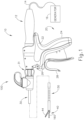
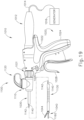
- FIG. 1 shows an exemplary ultrasonic surgical instrument (10). At least part of instrument (10) may be constructed and operable in accordance with at least some of the teachings of any of the various patents, patent application publications, and patent applications that are cited herein. As described therein and as will be described in greater detail below, instrument (10) is operable to cut tissue and seal or weld tissue (e.g., a blood vessel, etc.) substantially simultaneously.
- tissue and seal or weld tissue e.g., a blood vessel, etc.
- instrument (10) may have various structural and functional similarities with the HARMONIC ACE ® Ultrasonic Shears, the HARMONIC WAVE ® Ultrasonic Shears, the HARMONIC FOCUS ® Ultrasonic Shears, and/or the HARMONIC SYNERGY ® Ultrasonic Blades. Furthermore, instrument (110) may have various structural and functional similarities with the devices taught in any of the other references that are cited herein.
- Instrument (10) of the present example comprises a handle assembly (20), a shaft assembly (30), and an end effector (40).
- Handle assembly (20) comprises a body (22) including a pistol grip (24) and a pair of buttons (26).
- Handle assembly (20) also includes a trigger (28) that is pivotable toward and away from pistol grip (24). It should be understood, however, that various other suitable configurations may be used, including but not limited to a scissor grip configuration.
- End effector (40) includes an ultrasonic blade (160) and a pivoting clamp arm (44).
- Clamp arm (44) is coupled with trigger (28) such that clamp arm (44) is pivotable toward ultrasonic blade (160) in response to pivoting of trigger (28) toward pistol grip (24); and such that clamp arm (44) is pivotable away from ultrasonic blade (160) in response to pivoting of trigger (28) away from pistol grip (24).
- trigger (28) Various suitable ways in which clamp arm (44) may be coupled with trigger (28) will be apparent to those of ordinary skill in the art in view of the teachings herein.
- one or more resilient members are used to bias clamp arm (44) and/or trigger (28) to the open position shown in FIG. 1 .
- An ultrasonic transducer assembly (12) extends proximally from body (22) of handle assembly (20).
- Transducer assembly (12) is coupled with a generator (16) via a cable (14), such that transducer assembly (12) receives electrical power from generator (16).
- Piezoelectric elements in transducer assembly (12) convert that electrical power into ultrasonic vibrations.
- Generator (16) may include a power source and control module that is configured to provide a power profile to transducer assembly (12) that is particularly suited for the generation of ultrasonic vibrations through transducer assembly (12).
- generator (16) may comprise a GEN 300 sold by Ethicon Endo-Surgery, Inc. of Cincinnati, Ohio.
- generator (16) may be constructed in accordance with at least some of the teachings of U.S. Pub. No. 2011/0087212, entitled “Surgical Generator for Ultrasonic and Electrosurgical Devices,” published April 14, 2011 . It should also be understood that at least some of the functionality of generator (16) may be integrated into handle assembly (20), and that handle assembly (20) may even include a battery or other on-board power source such that cable (14) is omitted. Still other suitable forms that generator (16) may take, as well as various features and operabilities that generator (16) may provide, will be apparent to those of ordinary skill in the art in view of the teachings herein.
- end effector (40) of the present example comprises clamp arm (44) and ultrasonic blade (160).
- Clamp arm (44) includes a clamp pad (46) that is secured to the underside of clamp arm (44), facing blade (160).
- Clamp pad (46) may comprise polytetrafluoroethylene (PTFE) and/or any other suitable material(s).
- Clamp arm (44) is pivotally secured to a distally projecting tongue (43) of an upper distal shaft element (172), which is fixedly secured within a distal portion of a distal outer sheath (33).
- Clamp arm (44) is operable to selectively pivot toward and away from blade (160) to selectively clamp tissue between clamp arm (44) and blade (160).
- a pair of arms (156) extend transversely from clamp arm (44) and are pivotally secured to a lower distal shaft element (170), which is slidably disposed within the distal portion of distal outer sheath (33).
- a cable may be secured to lower distal shaft element (170). Such a cable may be operable to translate longitudinally relative to an articulation section (130) of shaft assembly (30) to selectively pivot clamp arm (44) toward and away from blade (160).
- the cable is coupled with trigger (28) such that the cable translates proximally in response to pivoting of trigger (28) toward pistol grip (24), and such that clamp arm (44) thereby pivots toward blade (160) in response to pivoting of trigger (28) toward pistol grip (24).
- the cable may translate distally in response to pivoting of trigger (28) away from pistol grip (24), such that clamp arm (44) pivots away from blade (160) in response to pivoting of trigger (28) away from pistol grip (24).
- Clamp arm (44) may be biased toward the open position, such that (at least in some instances) the operator may effectively open clamp arm (44) by releasing a grip on trigger (28).
- Blade (160) of the present example is operable to vibrate at ultrasonic frequencies in order to effectively cut through and seal tissue, particularly when the tissue is being compressed between clamp pad (46) and blade (160).
- Blade (160) is positioned at the distal end of an acoustic drivetrain.
- This acoustic drivetrain includes transducer assembly (12) and an acoustic waveguide (180).
- Acoustic waveguide (180) comprises a flexible portion (166).
- Transducer assembly (12) includes a set of piezoelectric discs (not shown) located proximal to a horn (not shown) of waveguide (180).
- the piezoelectric discs are operable to convert electrical power into ultrasonic vibrations, which are then transmitted along waveguide (180), including flexible portion (166) of waveguide (180) to blade (160) in accordance with known configurations and techniques.
- this portion of the acoustic drivetrain may be configured in accordance with various teachings of various references that are cited herein.
- flexible portion (166) of waveguide (180) includes a distal flange (136), a proximal flange (138), and a narrowed section (164) located between flanges (136, 138).
- flanges (136, 138) are located at positions corresponding to nodes associated with resonant ultrasonic vibrations communicated through flexible portion (166) of waveguide (180).
- Narrowed section (164) is configured to allow flexible portion (166) of waveguide (180) to flex without significantly affecting the ability of flexible portion (166) of waveguide (180) to transmit ultrasonic vibrations.
- narrowed section (164) may be configured in accordance with one or more teachings of U.S. Pub. No.
- waveguide (180) may be configured to amplify mechanical vibrations transmitted through waveguide (180).
- waveguide (180) may include features operable to control the gain of the longitudinal vibrations along waveguide (180) and/or features to tune waveguide (180) to the resonant frequency of the system.
- waveguide (180) may be mechanically and acoustically coupled with transducer assembly (12) will be apparent to those of ordinary skill in the art in view of the teachings herein.
- the distal end of blade (160) is located at a position corresponding to an anti-node associated with resonant ultrasonic vibrations communicated through flexible portion (166) of waveguide (180), in order to tune the acoustic assembly to a preferred resonant frequency f o when the acoustic assembly is not loaded by tissue.
- the distal end of blade (160) is configured to move longitudinally in the range of, for example, approximately 10 to 500 microns peak-to-peak, and in some instances in the range of about 20 to about 200 microns at a predetermined vibratory frequency f o of, for example, 55.5 kHz.
- transducer assembly (12) of the present example When transducer assembly (12) of the present example is activated, these mechanical oscillations are transmitted through waveguide (180) to reach blade (160), thereby providing oscillation of blade (160) at the resonant ultrasonic frequency.
- the ultrasonic oscillation of blade (160) may simultaneously sever the tissue and denature the proteins in adjacent tissue cells, thereby providing a coagulative effect with relatively little thermal spread.
- an electrical current may also be provided through blade (160) and clamp arm (44) to also cauterize the tissue.
- Shaft assembly (30) of the present example extends distally from handle assembly (20).
- shaft assembly (30) includes distal outer sheath (33) and a proximal outer sheath (32) that enclose clamp arm (44) drive features and the above-described acoustic transmission features.
- Shaft assembly (30) further includes an articulation section (130), which is located at a distal portion of shaft assembly (30), with end effector (40) being located distal to articulation section (130).
- a knob (31) is secured to a proximal portion of proximal outer sheath (32).
- Knob (31) is rotatable relative to body (22), such that shaft assembly (30) is rotatable about the longitudinal axis defined by outer sheath (32), relative to handle assembly (20). Such rotation may provide rotation of end effector (40), articulation section (130), and shaft assembly (30) unitarily. Of course, rotatable features may simply be omitted if desired.
- Articulation section (130) is operable to selectively position end effector (40) at various lateral deflection angles relative to a longitudinal axis defined by outer sheath (32).
- Articulation section (130) may take a variety of forms.
- articulation section (130) may be configured in accordance with one or more teachings of U.S. Pub. No. 2012/0078247 .
- articulation section (130) may be configured in accordance with one or more teachings of U.S. Pub. No. 2014/0005701 and/or U.S. Pub. No. 2014/0114334 .
- Various other suitable forms that articulation section (130) may take will be apparent to those of ordinary skill in the art in view of the teachings herein.
- articulation section (130) of this example comprises a set of three retention collars (133) and a pair of ribbed body portions (132, 134), with a pair of articulation bands (140, 142) extending along respective channels (135, 137) defined between interior surfaces of retention collars (133) and exterior surfaces of ribbed body portions (132, 134).
- Ribbed body portions (132, 134) are longitudinally positioned between flanges (136, 138) of flexible portion (166) of waveguide (180). In some versions, ribbed body portions (132, 134) snap together about flexible portion (166) of waveguide (180). Ribbed body portions (132, 134) are configured to flex with flexible portion (166) of waveguide (180) when articulation section (130) bends to achieve an articulated state.
- FIG. 3 shows ribbed body portions (132, 134) in greater detail.
- ribbed body portions (132, 134) are formed of a flexible plastic material, though it should be understood that any other suitable material may be used.
- Ribbed body portion (132) comprises a set of three ribs (150) that are configured to promote lateral flexing of ribbed body portion (132). Of course, any other suitable number of ribs (150) may be provided. Ribbed body portion (132) also defines a channel (135) that is configured to receive articulation band (140) while allowing articulation band (140) to slide relative to ribbed body portion (132).
- ribbed body portion (134) comprises a set of three ribs (152) that are configured to promote lateral flexing of ribbed body portion (134). Of course, any other suitable number of ribs (152) may be provided. Ribbed body portion (134) also defines a channel (137) that is configured to receive articulation band (142) while allowing articulation band (142) to slide relative to ribbed body portion (137).
- ribbed body portions (132, 134) are laterally interposed between articulation bands (140, 142) and flexible portion (166) of waveguide (180). Ribbed body portions (132, 134) mate with each other such that they together define an internal passage sized to accommodate flexible portion (166) of waveguide (180) without contacting waveguide (180).
- a pair of complementary distal notches (131A, 131B) formed in ribbed body portions (132, 134) align to receive a pair of inwardly projecting resilient tabs (38) of distal outer sheath (33).
- This engagement between tabs (37) and notches (139A, 139B) longitudinally secures ribbed body portions (132, 134) relative to proximal outer sheath (32).
- any other suitable kinds of features may be used to couple ribbed body portions (132, 134) with proximal outer sheath (32) and/or distal outer sheath (33).
- articulation bands (140, 142) are unitarily secured to upper distal shaft element (172).
- articulation bands (140, 142) translate longitudinally in an opposing fashion, this will cause articulation section (130) to bend, thereby laterally deflecting end effector (40) away from the longitudinal axis of shaft assembly (30) from a straight configuration as shown in FIG. 6A to an articulated configuration as shown in FIG. 6B .
- end effector (40) will be articulated toward the articulation band (140, 142) that is being pulled proximally.
- the other articulation band (140, 142) may be pulled distally by upper distal shaft element (172).
- the other articulation band (140, 142) may be driven distally by an articulation control.
- Ribbed body portions (132, 134) and narrowed section (164) are all sufficiently flexible to accommodate the above-described articulation of end effector (40).
- flexible acoustic waveguide (166) is configured to effectively communicate ultrasonic vibrations from waveguide (180) to blade (160) even when articulation section (130) is in an articulated state as shown in FIG. 6B .
- each flange (136, 138) of waveguide (180) includes a respective pair of opposing flats (192, 196).
- Flats (192, 196) are oriented along vertical planes that are parallel to a vertical plane extending through narrowed section (164) of flexible portion (166).
- Flats (192, 196) are configured to provide clearance for articulation bands (140, 142).
- flats (196) of proximal flange (138) accommodate articulation bands (140, 142) between proximal flange (138) and the inner diameter of proximal outer sheath (32); while flats (192) of distal flange (136) accommodate articulation bands (140, 142) between distal flange (136) and the inner diameter of distal outer sheath (33).
- flats (192, 196) could be substituted with a variety of features, including but not limited to slots, channels, etc., with any suitable kind of profile (e.g., square, flat, round, etc.).
- flats (192, 196) are formed in a milling process, though it should be understood that any other suitable process(es) may be used.
- waveguide (180) may include flats formed in accordance with at least some of the teachings of U.S. Pub. No. 2013/0289592, entitled “Ultrasonic Device for Cutting and Coagulating,” published October 31, 2013 .
- outer rings (133) are located at longitudinal positions corresponding to ribs (150, 152), such that three rings (133) are provided for three ribs (150, 152).
- Articulation band (140) is laterally interposed within channel (135) between rings (133) and ribbed body portion (132); while articulation band (142) is laterally interposed within channel (137) between rings (133) and ribbed body portion (134).
- Rings (133) are configured to keep articulation bands (140, 142) in a parallel relationship, particularly when articulation section (130) is in a bent configuration (e.g., similar to the configuration shown in FIG. 6B ).
- rings (133) may retain articulation band (140) such that articulation band (140) follows a curved path that complements the curved path followed by articulation band (142).
- channels (135, 137) are sized to accommodate respective articulation bands (140, 142) in such a way that articulation bands (140, 142) may still freely slide through articulation section (130), even with rings (133) being secured to ribbed body portions (150, 152).
- rings (133) may be secured to ribbed body portions (132, 134) in various ways, including but not limited to interference fitting, adhesives, welding, etc.
- articulation bands (140, 142) When articulation bands (140, 142) are translated longitudinally in an opposing fashion, a moment is created and applied to a distal end of distal outer sheath (33) via upper distal shaft element (172). This causes articulation section (130) and narrowed section (164) of flexible portion (166) of waveguide (180) to articulate, without transferring axial forces in articulation bands (140, 142) to waveguide (180). It should be understood that one articulation band (140, 142) may be actively driven distally while the other articulation band (140, 142) is passively permitted to retract proximally.
- one articulation band (140, 142) may be actively driven proximally while the other articulation band (140, 142) is passively permitted to advance distally.
- one articulation band (140, 142) may be actively driven distally while the other articulation band (140, 142) is actively driven proximally.
- articulation bands (140, 142) may be driven will be apparent to those of ordinary skill in the art in view of the teachings herein.
- an articulation control assembly (100) is secured to a proximal portion of outer sheath (32).
- Articulation control assembly (100) comprises a housing (110) and a rotatable knob (120).
- Housing (110) comprises a pair of perpendicularly intersecting cylindrical portions (112, 114).
- Knob (120) is rotatably disposed within a first hollow cylindrical portion (112) of housing (110) such that knob (120) is operable to rotate within cylindrical portion (112) of housing (110).
- Shaft assembly (30) is slidably and rotatably disposed within a second cylindrical portion (114).
- Shaft assembly (30) comprises a pair of translatable members (161, 162), both of which extend slidably and longitudinally through the proximal portion of outer sheath (32).
- Translatable members (161, 162) are longitudinally translatable within second cylindrical portion (114) between a distal position and a proximal position.
- Translatable members (161, 162) are mechanically coupled with respective articulation bands (140, 142) such that longitudinal translation of translatable member (161) causes longitudinal translation of articulation band (140), and such that longitudinal translation of translatable member (162) causes longitudinal translation of articulation band (142).
- Knob (120) comprises a pair of pins (122, 124) extending downwardly from a bottom surface of knob (120).
- Pins (122, 124) extend into second cylindrical portion (114) of housing (110) and are rotatably and slidably disposed within a respective pair of channels (163, 164) formed in top surfaces of translatable members (161, 162).
- Channels (163, 164) are positioned on opposite sides of an axis of rotation of knob (120), such that rotation of knob (120) about that axis causes opposing longitudinal translation of translatable members (161, 162).
- rotation of knob (120) in a first direction causes distal longitudinal translation of translatable member (161) and articulation band (140), and proximal longitudinal translation of translatable member (162) and articulation band (142); and rotation of knob (120) in a second direction causes proximal longitudinal translation of translatable member (161) and articulation band (140), and distal longitudinal translation of translatable member (162) and articulation band (142).
- rotation of rotation knob (120) causes articulation of articulation section (130).
- Housing (110) of articulation control assembly (100) comprises a pair of set screws (111, 113) extending inwardly from an interior surface of first cylindrical portion (112). With knob (120) rotatably disposed within first cylindrical portion (112) of housing (110), set screws (111, 113) are slidably disposed within a pair of arcuate channels (121, 123) formed in knob (120). Thus, it should be understood that rotation of knob (120) will be limited by movement of set screws (111, 113) within channels (121, 123). Set screws (111, 113) also retain knob (120) in housing (110), preventing knob (120) from traveling vertically within first cylindrical portion (112) of housing (110).
- first cylindrical portion (112) of housing (110) comprises a first angular array of teeth (116) and a second angular array of teeth (118) formed in an interior surface of first cylindrical portion (112).
- Rotation knob (120) comprises a pair of outwardly extending engagement members (126, 128) that are configured to engage teeth (116, 118) of first cylindrical portion (112) in a detent relationship to thereby selectively lock knob (120) in a particular rotational position.
- the engagement of engagement members (126, 128) with teeth (116, 118) may be overcome by a user applying sufficient rotational force to knob (120); but absent such force, the engagement will suffice to maintain the straight or articulated configuration of articulation section (130). It should therefore be understood that the ability to selectively lock knob (120) in a particular rotational position lock will enable an operator to selectively lock articulation section (130) in a particular deflected position relative to the longitudinal axis defined by outer sheath (32).
- articulation section (130) of shaft assembly (30) is operable to achieve articulation angles up to between approximately 15° and approximately 30°, both relative to the longitudinal axis of shaft assembly (30) when shaft assembly (30) is in a straight (non-articulated) configuration.
- articulation section (130) may be operable to achieve any other suitable articulation angles.
- narrowed section (164) of waveguide (180) has a thickness between approximately 0.25mm (0.01 inches) and approximately 0.50mm (0.02 inches). Alternatively, narrowed section (164) may have any other suitable thickness. Also in some versions, narrowed section (164) has a length of between approximately 10mm (0.4 inches) and approximately 16mm (0.65 inches). Alternatively, narrowed section (164) may have any other suitable length. It should also be understood that the transition regions of waveguide (180) leading into and out of narrowed section (164) may be quarter rounded, tapered, or have any other suitable configuration.
- flanges (136, 138) each have a length between approximately 2.5mm (0.1 inches) and approximately 5.0mm (0.2 inches). Alternatively, flanges (136, 138) may have any other suitable length. It should also be understood that the length of flange (136) may differ from the length of flange (138). Also in some versions, flanges (136, 138) each have a diameter between approximately 4.45mm (0.175 inches) and approximately 5.0mm (0.2 inches). Alternatively, flanges (136, 138) may have any other suitable outer diameter. It should also be understood that the outer diameter of flange (136) may differ from the outer diameter of flange (138).
- articulation section such as articulation section (130) described above.
- articulation sections of some examples may be susceptible to some "play" or other small movement of the articulation section despite being relatively fixed in a given position, such that the articulation section is not entirely rigid. It may be desirable to reduce or eliminate such play in the articulation section, particularly when the articulation section is in a straight, non-articulated configuration. In some examples, such play may be reduced or eliminated by including features for selectively increasing tension in one or two articulation bands similar to articulation bands (140, 142) described above.
- Such features may reduce or eliminate play in the articulation section because the increased tension in the articulation bands may cause the components of the articulation section to longitudinally compress, thereby increasing the rigidity of the articulation section. It may be desirable to provide control of such features via the handle assembly and/or via the shaft assembly because such positioning may provide enhanced usability, ergonomics, and/or functionality.
- one or more resilient members resiliently bias articulation bands (140, 142) proximally in order to increase tension in articulation bands (140, 142).
- one or more resilient members may be used to resiliently bias articulation bands (140, 142) proximally will be apparent to those of ordinary skill in the art in view of the teachings herein.
- tension is selectively increased in one articulation band (140, 142) in order to effectively ridigize the articulation section.
- tension is selectively increased in both articulation bands (140, 142) simultaneously in order to effectively ridigize the articulation section.
- tension is selectively increased in both articulation bands (140, 142) simultaneously in order to effectively ridigize the articulation section.
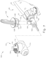
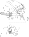
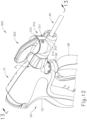
- FIGS. 8-11 show an exemplary alternative articulation control assembly (200) that may be readily incorporated into instrument (10). Except as otherwise noted herein, it should be understood that articulation control assembly (200) is substantially the same as articulation control assembly (100) described above.
- articulation control assembly (200) comprises a housing (210) and a rotatable knob (220).
- housing (210) of the present example comprises a pair of perpendicularly intersecting cylindrical portions (212, 214).
- knob (220) is rotatably disposed within a first hollow cylindrical portion (212) of housing (210) such that knob (220) is operable to rotate within cylindrical portion (212) of housing (210).
- Shaft assembly (30) is similarly slidably and rotatably disposed within a second cylindrical portion (214).
- Shaft assembly (30) comprises a pair of translatable members (261, 262), both of which extend slidably and longitudinally through the proximal portion of outer sheath (32).
- Translatable members (261, 262) are each longitudinally translatable within second cylindrical portion (214) between a distal position and a proximal position.
- translatable members (261, 262) are mechanically coupled with respective articulation bands (140, 142) such that longitudinal translation of translatable member (261) causes longitudinal translation of articulation band (140), and such that longitudinal translation of translatable member (262) causes longitudinal translation of articulation band (142).
- Knob (220) comprises a pair of pins (222, 224) extending downwardly from a bottom surface of knob (220).
- Pins (222, 224) extend into second cylindrical portion (214) of housing (210) and are rotatably and slidably disposed within a respective pair of channels (263, 264) formed in top surfaces of translatable members (261, 262).
- pins (222, 224) of the present example each include a cam surface (229) on the proximal side of each pin (222, 224), as best seen in FIGS. 9-11 .
- each cam surface (229) is configured to engage channels (263, 264) of translatable members (261, 262) to selectively drive translatable members (261, 262) proximally.
- Channels (263, 264), like channels (163, 164) described above, are positioned on opposite sides of an axis of rotation of knob (220), such that rotation of knob (220) about that axis causes opposing longitudinal translation of translatable members (261, 262).
- rotation of knob (220) in a first direction causes distal longitudinal translation of translatable member (261) and articulation band (140), while simultaneously causing proximal longitudinal translation of translatable member (262) and articulation band (142).
- Rotation of knob (220) in a second direction causes proximal longitudinal translation of translatable member (261) and articulation band (140), while simultaneously causing distal longitudinal translation of translatable member (262) and articulation band (142).
- rotation of knob (220) causes articulation of articulation section (130) as previously described with respect to instrument (10).
- housing (210) of the present example comprises a pair of detent features (211, 213) extending inwardly from an interior surface of first cylindrical portion (212).
- detent features (211, 213) of the present example are shown as ball and spring detents, it should be understood that any other suitable detent feature may be used.
- knob (220) rotatably disposed within first cylindrical portion (212) of housing (210)
- detent features (211, 213) are configured to permit knob (220) to be selectively repositioned such that detent features (211, 213) may be disposed within a pair of first arcuate channels (221, 223) or a pair of second arcuate channels (225, 227) formed in knob (220).
- knob (220) will be limited by movement of detent features (211, 213) within channels (221, 223, 225, 227).
- Detent features (211, 213) also retain knob (220) in housing (210), while permitting knob (220) to be selectively positioned between a first vertical position and a second vertical position within first cylindrical portion (212) of housing (210).
- first cylindrical portion (212) of the present example further comprises a first angular array of teeth (216) and a second angular array of teeth (218) formed in an interior surface of first cylindrical portion (212).
- Rotatable knob (220) comprises a pair of outwardly extending engagement members (226, 228) that are configured to engage teeth (216, 218) of first cylindrical portion (212) in a detent relationship to thereby selectively lock knob (220) in a given rotational position.
- the engagement of engagement members (226, 228) with teeth (216, 218) may be overcome by a user applying sufficient rotational force to knob (220); but absent such force, the engagement will suffice to maintain the straight or articulated configuration of articulation section (230). It should therefore be understood that the ability to selectively lock knob (220) in a particular rotational position will enable an operator to selectively lock articulation section (230) in a particular deflected position relative to the longitudinal axis defined by outer sheath (32).
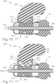
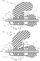
- FIGS. 10 and 11 show an exemplary use of articulation control assembly (200).
- articulation control assembly (200) may be initially configured such that knob (220) is in the first vertical position.
- the first position of knob (220) corresponds to articulation bands (140, 142) being in high tension to thereby increase the rigidity of articulation section (130).
- cam surface (229) of each pin (222, 224) fully engages a corresponding cam surface (265) of each channel (263, 264) in each translatable member (261, 262).
- Detent features (211, 213) maintain knob (220) in the first position because detent features (211, 213) resiliently engage arcuate channels (221, 223) of knob (220).
- an operator will first have to decrease the rigidity of articulation section (130).
- an operator may transition knob (220) to the second vertical position as seen in FIG. 11 .
- an operator may apply an upward force to knob (220) by pulling upwardly on knob (220) while holding housing (210) stationary.
- Such an upward force should be sufficient to overcome the resiliency of detent features (211, 213) to thereby disengage detent features from arcuate channels (221, 223).
- knob (220) is in the second vertical position, the tension in articulation bands (140, 142) is released and articulation section (130) is in a configuration for articulation.
- knob (220) is positioned relative to each translatable member (261, 262) such that cam surface (229) of each pin (222, 224) only partially engages the corresponding cam surface (265) defined by each translatable member (261, 262). Such engagement may permit each translatable member (261, 262) to translate distally thereby reducing the tension in articulation bands (140, 142).
- knob (220) When knob (220) is in the second position, such a positioning may be visually indicated by an indicator (219) on knob (220).
- indicator (219) (as seen in FIG. 9 ) is shown as a red stripe around the exterior of knob (220).
- indicator (219) When knob (220) is in the first position, indicator (219) is covered by cylindrical portion (212) of housing (210) and is thereby obscured from view. Yet in the second position, indicator (219) is visible because knob (220) is in a higher vertical position relative to housing (210), such that indicator (219) is exposed.
- indicator (219) is shown as a red stripe in the present example, it should be understood in other examples, any other color or any other type of indicator may be used.
- an operator may articulate articulation section (130) by applying a rotational force to knob (220) to thereby rotate knob (220).
- pins (222, 224) drive translatable members (261, 262) in opposing directions as described above thereby articulating articulation section (130).
- an operator may cease rotation of knob (220).
- an operator may force knob (220) downwardly to the first position as described above in order to effectively ridigize articulation section (130).
- articulation section (130) may only be rigidized by forcing knob (220) downwardly to the second vertical position when articulation section (130) is in a straight, non-articulated configuration.
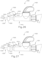
- FIGS. 12-14 show an exemplary alternative articulation control assembly (300) that may be readily incorporated into instrument (10). Except as otherwise noted herein, it should be understood that articulation control assembly (300) is substantially the same as articulation control assembly (100) described above.
- articulation control assembly (300) comprises a housing (310) and a rotatable knob (320).
- housing (310) of the present example comprises a pair of perpendicularly intersecting cylindrical portions (312, 314).
- knob (320) is rotatably disposed within a first hollow cylindrical portion (312) of housing (310) such that knob (320) is operable to rotate within cylindrical portion (312) of housing (310).
- Shaft assembly (30) is similarly slidably and rotatably disposed within a second cylindrical portion (314).
- shaft assembly (30) comprises a pair of translatable members (361) (though only a single translatable member is shown), both of which extend slidably and longitudinally through the proximal portion of outer sheath (32).
- Translatable members (361) are each longitudinally translatable within second cylindrical portion (314) between a distal position and a proximal position.
- translatable members (361) are mechanically coupled with respective articulation bands (140, 142) such that longitudinal translation of translatable member (361) causes longitudinal translation of articulation band (140), and such that longitudinal translation of the other translatable member (not shown) causes longitudinal translation of articulation band (142).
- Knob (320) comprises a pair of pins (324) (though only a single pin is shown) extending downwardly from a bottom surface of knob (320).
- Pins (324) extend into second cylindrical portion (314) of housing (310) and are rotatably and slidably disposed within a respective pair of channels (363) (though only a single channel is shown) formed in top surfaces of translatable members (361).
- Channels (363), like channels (163, 164) described above, are positioned on opposite sides of an axis of rotation of knob (320), such that rotation of knob (320) about that axis causes opposing longitudinal translation of translatable members (361).
- rotation of knob (320) in a first direction causes distal longitudinal translation of translatable member (361) and articulation band (140), while simultaneously causing proximal longitudinal translation of translatable member and articulation band (142).
- Rotation of knob (320) in a second direction causes proximal longitudinal translation of translatable member (361) and articulation band (140), while simultaneously causing distal longitudinal translation of translatable member and articulation band (142).
- rotation of knob (320) causes articulation of articulation section (130) a previously described with respect to instrument (10).
- housing (310) of the present example comprises a single set screw (313) extending inwardly from an interior surface of first cylindrical portion (312).
- set screw (313) is slidably disposed within an arcuate channel (323) formed in knob (320).
- Rotation of knob (320) will be limited by movement of set screws (313) within channel (323).
- Set screw (313) also retain knob (320) in housing (310), preventing knob (320) from traveling vertically within first cylindrical portion (312) of housing (310).
- Housing (310) further includes an open portion (311).
- open portion (311) is disposed on the distal face of housing (310) and is formed as a vertically extending channel that interrupts the circumference of cylindrical portion (312).
- open portion (311) is configured to permit at least a portion of knob (320) to pass distally through housing (310).
- open portion (311) is configured to permit passage of at least a portion of knob (320) because such a feature permits at least a portion of knob (320) to be pivotable relative to housing (310).
- a knob lock (315) is disposed adjacent to open portion (311).
- Knob lock (315) is configured to selectively lock and unlock pivoting of knob (320) by selectively closing at least a portion of open portion (311) or otherwise engaging knob (320) to prevent pivoting.
- knob lock (315) may comprise a "C" shaped member that selectively rotates about cylindrical portion (312) to selectively close off or open the open portion (311) of cylindrical portion (312).
- knob lock (315) may comprise a protrusion that selectively extends into or over a portion of open portion (311).
- Various suitable ways in which a knob lock (315) may be configured and operable will be apparent to those of ordinary skill in the art in view of the teachings herein.
- first cylindrical portion (312) of the present example comprises a first angular array of teeth (not shown) and a second angular array of teeth (not shown) formed in an interior surface of first cylindrical portion (312).
- knob (320) comprises a pair of outwardly extending engagement members (not shown) that are configured to engage the teeth of first cylindrical portion (312) in a detent relationship to thereby selectively lock knob (320) in a given rotational position.
- the engagement of the engagement members with the teeth may be overcome by a user applying sufficient rotational force to knob (320); but absent such force, the engagement will suffice to maintain the straight or articulated configuration of articulation section (330). It should therefore be understood that the ability to selectively lock knob (320) in a particular rotational position lock will enable an operator to selectively lock articulation section (330) in a particular deflected position relative to the longitudinal axis defined by outer sheath (32).
- FIGS. 13 and 14 show an exemplary use of articulation control assembly (200) to selectively stiffen articulation section (130). It should be understood that in some examples it may be desirable to pivot articulation control assembly (200) to selectively stiffen articulation section (130) because such a feature may improve usability and/or ergonomics.
- articulation control assembly (300) may be initially configured such that knob (320) is in a first pivotal position. It should be understood that in the present example the first pivotal position of knob (320) corresponds to articulation bands (140, 142) being relatively relaxed to such that articulation bands (140, 142) are in a configuration for articulating articulation section (130).
- first pivotal position corresponds to knob (320) being seated within first cylindrical portion (312) of housing (310).
- knob (320) is positioned to rotate within first cylindrical position (312) about a rotation axis to opposingly drive translatable members (361) via pins (324). Accordingly, an operator may rotate knob (320) about the rotation axis while knob (320) is in the first pivotal position in order to articulate articulation section (130). Additionally, to maintain knob (320) within first cylindrical portion (312) while the articulation feature is in use, an operator may optionally engage knob lock (315) in a locked position.
- an operator may first transition knob lock (315) to an unlocked position to thereby permit pivotal motion of knob (320) about a pivot axis.
- the pivot axis is perpendicular to the rotation axis of knob (320) and offset from the rotation axis of knob (320).
- the pivot axis is also perpendicular to the longitudinal axis of shaft assembly (30) and offset from the longitudinal axis of shaft assembly (30).
- the pivot axis runs into and out of the page
- the rotation axis runs vertically between the top of the view and the bottom of the view
- the longitudinal axis runs horizontally between the sides of the view.
- knob lock (315) is in the unlocked position, at least a portion of knob (320) is permitted to pass through open portion (311) of housing (310).
- an operator may next apply a horizontal force to knob (320) (e.g., to the left-hand side of the view shown in FIGS. 13-14 ) while holding housing (310) stationary.
- Such a horizontal force acting on knob (320) may begin to pivot knob (320) about the pivot axis toward the position shown in FIG. 14 .
- knob (320) is comprised of three separate components - a pivoting member, and two side members.
- the pivoting member is be secured to each of the side members by a shaft suitable for pivoting the pivoting member relative to the two side members.
- first cylindrical portion (312) may be equipped with a hinge member or other feature that may be equipped to permit both knob (320) and first cylindrical portion (312) to pivot relative to second cylindrical portion (314).
- any other suitable mechanism for pivoting knob (320) may be used as will be apparent to those of ordinary skill in the art in view of the teachings herein.
- knob (320) Regardless of the particular mechanism for pivoting knob (320), it should be understood that as knob (320) is pivoted, the pivoting action generally applies tension to articulation bands (140, 142) via pins (324) and translatable members (361), thereby increasing the rigidity of articulation section (130).
- the pivoting of knob (320) causes pins (324) to move about the pivot axis. As pins (324) move, pins (324) engage a proximal portion of each translatable member (361) such that further movement of pins (324) will simultaneously drive each translatable member (361) proximally.
- knob (320) may be pivoted to the position shown in FIG. 14 only when articulation section (130) is in a straight, non-articulated configuration. Some other versions may permit knob (320) to be pivoted to the position shown in FIG. 14 when articulation section (130) is in an articulated configuration.
- knob (320) pivoted to a fully pivoted position shown in FIG. 14 , articulation bands (140, 142) are in a tensioned configuration and articulation section (130) is correspondingly in a rigid configuration.
- knob lock (315) engages at least a portion of knob (320) to maintain knob (320) in the fully pivoted position.
- knob (320) comprises openings, indentations, or other features that receive a portion of knob lock (314), thereby permitting knob lock (315) to engage knob (320).
- FIGS. 15 and 16 show an exemplary alternative articulation section that may be readily incorporated into instrument (10).
- articulation section (430) is substantially the same as articulation section (130) described above.
- articulation section (430) comprises a pair of ribbed body portions (432, 434) surrounding flexible portion (166) of waveguide (180).
- ribbed body portions (432, 434) are configured to flex with flexible portion (466) of waveguide (180) when articulation section (430) bends to achieve an articulated state.
- articulation section (430) includes a plurality of retention collars (433).
- retention collars (433) of the present example are configured to surround ribbed body portions (432, 434) and are configured to retain articulation bands (140, 142), retention collars (433) are also generally configured for the purpose of providing rigidity to articulation section (430).
- retention collars (433) of the present example are generally wider compared to retention collars (133). With such a width, it should be understood that retention collars (433) substantially abut each other.
- Each retention collar (433) is asymmetrical and comprises an articulating portion (435) and a locking portion (437).
- Each articulating portion (435) comprises a chamfered edge (436) on each side of each articulating portion (435).
- each chamfered edge (436) is generally at an oblique angle suitable to permit articulation of articulation section (430).
- each chamfered edge (436) is at an angle of about 15° relative to the longitudinal axis of each retention collar (433), although any other suitable angle may be used.
- Each locking portion (437) is generally square or rectangular in shape. Accordingly, each locking portion (437) forms a generally straight edge (438) positioned adjacent to each chamfered edge (436) of each articulating portion (435). As will be understood, each straight edge (438) is generally configured to maintain rigidity of articulation section (430) in a given direction when each retention collar (433) is adjacent to the others.
- FIGS. 15 and 16 show an exemplary operation of articulation section (430).
- articulation section (430) is generally both unidirectionally rigid and unidirectionally articulable. For instance, if a transversely oriented force is applied to the distal portion of shaft assembly (30) in the direction of locking portions (437) and perpendicular to the longitudinal axis of shaft assembly (30), articulation section (430) resists articulation because each straight edge (438) of each locking portion (437) that is adjacent to another straight edge (438) engages with the other straight edge (438) and thus prevents lateral bending of articulation section (430).
- articulation section (430) may be articulated because chamfered edges (436) of each articulating portion (435) provide sufficient clearance to permit lateral bending of articulation section (430).
- articulating portions (435) permit articulation, it should be understood that articulating portions (435) only permit articulation to the extent that chamfered edges (436) remain away from each other.
- each chamfered edge (436) will act as a physical stop to further articulation similarly to straight edges (438) of each locking portion (437).
- both chamfered edges (436) and straight edges (438) act as physical stops that prevent articulation of articulation section (430), but straight edges (438) permit very little to no articulation, while chamfered edges (436) permit a certain predetermined range of articulation.
- articulation bands (140, 142) are neither in tension nor compression, an operator may apply an articulation force to articulate articulation section (430) in only a single direction and only to a certain predetermined extent.
- chamfered edges (436) may permit articulation section (430) to achieve an articulation angle of up to approximately 30°.
- any other suitable maximum articulation angle may be provided. It should be understood that the "articulation angle" may be an angle defined between the longitudinal axis of distal outer sheath (33) and the longitudinal axis of proximal outer sheath (32).
- articulation section (430) When an operator desires to lock articulation section (430) in a straight configuration as seen in FIG. 15 , a user may place at least articulation band (141) in tension thereby compressing retention collars (433) such that straight edges (438) of locking portions (437) are compressed against each other. While straight edges (438) will prevent articulation in the direction of locking portions (437), tension in articulation band (141) will also prevent articulation in the direction toward articulating portions (435). This is because the tension in articulation band (140) will prevent straight edges (438) from separating relative to each other.
- Tension may be applied to articulation band (140) using the articulation control assemblies (110, 210, 310) described above, or any other suitable means.
- Articulation band (142) may also be placed in tension using the features of articulation assemblies (210, 310) described above, or any other suitable means.
- articulation band (142) may merely be passive in state with merely no force applied.
- an operator may release tension from articulation band (140). Once tension is released from articulation band (140), articulation section (430) will be in the passive state described above where articulation is permitted in the direction of articulating portions (435) but not in the direction of locking portions (437).
- an operator may place articulation band (142) in tension while maintaining articulation band (140) in a passive state or actively driving articulation band (140) distally.
- Tension may be applied to articulation band (140) using articulation control assemblies (110, 210, 310) as described above, or by using any other suitable means.
- articulation band (142) As tension is applied, articulation band (142) generates a moment that bends articulation section (430). Articulation section (430) is then permitted to bend until chamfered edges (436) of articulating portions (435) are adjacent to each other. At such a point chamfered edges (436) begin acting as physical stops as described above thereby preventing further articulation.
- FIG. 17 shows an exemplary alternative housing (510) that may be readily incorporated into instrument (10), particularly when instrument (10) is equipped with articulation section (430) described above. Unless otherwise described herein, it should be understood that housing (510) is substantially the same as housing (110) described above. Additionally, it should be understood that any of the features described herein with respect to housing (510) may be readily incorporated into any housings (110, 210, 310) described above.
- housing (510) comprises a first cylindrical portion (512) and a second cylindrical portion (514).
- Second cylindrical portion (514) is substantially the same as second cylindrical portion (114) described above such that further details will not be described herein.
- First cylindrical portion (512) is substantially the same as first cylindrical portion (112) described above.
- first cylindrical portion (512) comprises a first angular array of teeth (516) and a second angular array of teeth (518) formed in an interior surface of first cylindrical portion (512).
- teeth (516, 518) of the present example are configured for use with articulation section (430) described above.
- each angular array of teeth (516, 518) comprises a respective plurality of articulation teeth (520, 522), a single lock tooth valley (524, 526), and an exaggerated tooth (528, 529) separating the articulation teeth (520, 522) from the lock tooth valley (524, 526).
- Each set of articulation teeth (520, 522) functions similarly to teeth (116, 118) described above.
- articulation teeth (520, 522) are configured to engage engagement members (126, 128) of rotatable knob (120) such that knob (120) may be rotated to articulate articulation section (430) to a desired position and remain in the same position once any rotational force is removed from knob (120).
- articulation teeth (520, 522) are disposed for movement of articulation section (430) in only a single direction because, as described above, articulation section (430) is only configured for articulation in a single direction.
- Each lock tooth valley (524, 526) is configured to hold knob (120) in a position corresponding to a locked position of articulation section (430). It should be understood that each lock tooth valley (524, 526) is disposed in a position corresponding to knob (120) being rotated slightly past a neutral position (e.g., the position aligned with the longitudinal axis of instrument (10)). This positioning ensures that some tension will be applied to actuation band (140) to achieve the locking configuration described above with respect to articulation section (430) while articulation section (430) is in a substantially straight, non-articulated configuration. Although each lock tooth valley (524, 526) of the present example is shown in a given position, it should be understood that the precise position of each lock tooth valley (524, 526) may be varied as desired to achieve a sufficient level of tension in actuation band (140).
- Each exaggerated tooth (528, 529) is positioned between each set of actuation teeth (520, 522) and each lock tooth valley (524, 526).
- Each exaggerated tooth (528, 529) is configured to act as a detent feature that may provide additional support to hold knob (120) in the locked position described above.
- each exaggerated tooth (528, 529) is configured to engage engagement members (126, 128) to hold engagement members (126, 128) respective lock tooth valleys (524, 526).
- each exaggerated tooth (528, 529) may act to provide tactile feedback to an operator as knob (120) is transitioned between each set of actuation teeth (520, 522) and each lock tooth valley (524, 526).
- each exaggerated tooth (528, 529) of the present example is shown as having a particular size, it should be understood that the configuration of exaggerated tooth (528, 529) may be varied as desired to achieve suitable detent and/or tactile feedback characteristics.
- FIG. 18 shows another exemplary alternative articulation section (630) that may be readily incorporated into instrument (10).
- Articulation section (630) comprises three articulation segments (632, 642, 652) disposed between a distal block (660) and a proximal block (664).
- Articulation segments (632, 642, 652) are configured to operate cooperatively to act as physical stops for different amounts of articulation for a given side of each articulation segment (632, 642, 652).
- Articulation segments (632, 642, 652) consist of a first articulation segment (632), a second articulation segment (642), and a third articulation segment (652).
- any suitable number of articulation segments (632, 642, 652) may be used.
- a plurality of second articulation segments (642) may be incorporated between first and third articulation segments (632, 652).
- second articulation segment (642) may be omitted altogether with first and third articulation segments (632, 652) being adjacent to each other.
- First articulation segment (632) includes an articulation portion (633) and a lock portion (636).
- Articulation portion (633) comprises a straight end (634) disposed adjacent to distal block (660) and a chamfered end (635) disposed adjacent to second articulation segment (642).
- Straight end (634) is generally straight and is configured to rest squarely against distal block (660).
- Chamfered end (635) is configured with a chamfer disposed at an angle of approximately 15° relative to the longitudinal axis of first articulation segment (632).
- chamfered end (635) is generally configured to permit articulation of articulation section (630) for a certain amount of articulation (e.g., approximately 30°) before acting as a physical stop.
- Lock portion (636) comprises a straight end (637) and a chamfered end (638).
- Straight end (637) is generally straight and is configured to rest squarely against distal block (660).
- Chamfered end (638) is configured with a chamfer disposed at an angle of approximately 1° to 5° relative to the longitudinal axis of first articulation segment (632). While chamfered end (638) is configured to permit some articulation of articulation section (630), it should be understood that chamfered end (638) is configured to permit only a limited amount of articulation prior to acting as a physical stop. This is because of the relatively shallow chamfer angle as compared to the chamfer angle of chamfered end (635) described above. Accordingly, as will be described in greater detail below, lock portion (636) generally acts a physical stop for articulation in articulation section (630) despite allowing some relatively limited amount of articulation.
- Second articulation segment (642) includes an articulation portion (643) and a lock portion (646).
- Articulation portion (643) comprises two chamfered ends (644, 645) with a distal chamfered end (644) disposed adjacent to first articulation segment (632) and a proximal chamfered end (645) disposed adjacent to third articulation segment (652).
- Chamfered ends (644, 645) are generally symmetrical and are both configured with a chamfer disposed at an angle of approximately 15° relative to the longitudinal axis of second articulation segment (642).
- chamfered ends (644, 645) are generally configured to permit articulation of articulation section (630) for a certain amount of articulation (e.g., approximately 30°) before acting as a physical stop.
- Lock portion (646) comprises two chamfered ends (647, 648) with a distal chamfered end (647) disposed adjacent to first articulation segment (632) and a proximal chamfered end (648) disposed adjacent to third articulation segment (652).
- Chamfered ends (637, 638) are both configured with a chamfer disposed at an angle of approximately 1° to 5° relative to the longitudinal axis of second articulation segment (642). While chamfered ends (647, 648) are configured to permit some articulation of articulation section (630), it should be understood that chamfered ends (647, 648) are configured to permit only a limited amount of articulation prior to acting as a physical stop.
- lock portion (646) generally acts a physical stop for articulation in articulation section (630) despite allowing some relatively limited amount of articulation.
- Third articulation segment (652) is similar to first articulation segment (632) and includes an articulation portion (653) and a lock portion (656).
- Articulation portion (653) comprises a chamfered end (654) disposed adjacent to second articulation segment (642) and a straight end (655) disposed adjacent to proximal block (664).
- Chamfered end (654) is configured with a chamfer disposed at an angle of approximately 15° relative to the longitudinal axis of third articulation segment (652).
- chamfered end (654) is generally configured to permit articulation of articulation section (630) for a certain amount of articulation (e.g., approximately 30°) before acting as a physical stop.
- Straight end (655) is generally straight and is configured to rest squarely against proximal block (664).
- Lock portion (656) comprises a chamfered end (657) and a straight end (658).
- Chamfered end (657) is configured with a chamfer disposed at an angle of approximately 1° to 5° relative to the longitudinal axis of third articulation segment (652). While chamfered end (657) is configured to permit some articulation of articulation section (630), it should be understood that chamfered end (657) is configured to permit only a limited amount of articulation prior to acting as a physical stop. This is because of the relatively shallow chamfer angle as compared to the chamfer angle of chamfered end (654) described above.
- lock portion (656) generally acts a physical stop for articulation in articulation section (630) despite allowing some relatively limited amount of articulation.
- Straight end (658) is generally straight and is configured to rest squarely against proximal block (664).
- Each articulation segment (632, 642, 652) includes a respective bore (639, 649, 659) extending transversely therethough.
- Each bore (639, 649, 659) is configured to surround but not contact waveguide (180). For instance, each bore (639, 649, 659) is cut into a larger portion of each respective lock portion (636, 646, 656) relative to each respective articulation portion (633, 643, 653). Because each articulation portion (633, 643, 653) is configured to articulate articulation section (630) a larger amount relative to each lock portion (636, 646, 656), each bore (639, 649, 659) is configured to include additional space on the side of each lock portion (636, 646, 656) to accommodate bending of waveguide (180).
- Distal and proximal block (660, 664) each similarly include a respective bore (662, 666) that is configured to surround waveguide (180) without contacting waveguide (180). Additionally, blocks (660, 664) are configured to abut articulation segments (632, 642, 652) and to provide a stable point of contact for segments (632, 642, 652). Although not shown, it should be understood that blocks (660, 664) may also include channels or other features configured to provide a surface for articulation bands (140, 142) to move upon.
- an operator may lock articulation section (630) in a generally straight configuration by applying tension to articulation band (140).
- tension may be applied using articulation control assemblies (100, 200, 300) as described above.
- articulation control assemblies 100, 200, 300
- a moment will be created by such tension that will urge chamfered ends (638, 647) of first and second articulation segments (632, 642) toward each other and chamfered ends (648, 657) of second and third articulation segments (642, 652) toward each other until each chamfered end (638, 647, 648, 657) abuts another. Because of the limited chamfer of chamfered ends (638, 647, 648, 657) any articulation of articulation section (630) will be limited at this stage.
- chamfered ends (638, 647, 648, 657) are abutting, additional articulation will be prevented by physical contact between chamfered ends (638, 647, 648, 657).
- articulation section (130) will be held in a position of limited to no articulation. It should be understood that the particular amount of articulation of articulation section (630) will be determined by the particular chamfer angles of chamfered ends (638, 647, 648, 657).
- an operator may first release any tension in articulation band (140). Once tension is released, an operator may apply tension to articulation band (142) using articulation control assembly (100, 200, 300) described above. One tension is applied to articulation band (142), a moment will be created by such tension that will urge chamfered ends (635, 644) of first and second articulation segments (632, 642) toward each other and chamfered ends (645, 654) of second and third articulation segments (642, 652) toward each other until each chamfered end (635, 644, 645, 654) abut another.
- articulation of articulation section (630) about articulation portions (633, 643, 653) will be relatively large in comparison to articulation about lock portions (636, 646, 656). In some examples, such an articulation of articulation section will be approximately 30°.
- chamfered ends (635, 644, 645, 654) are abutting, additional articulation will be prevented by physical contact between chamfered ends (635, 644, 645, 654).
- articulation band (140) While tension is applied to articulation band (140), articulation section (130) will be held in an articulated position.
- chamfered ends (635, 644, 645, 654) may be configured to permit any suitable amount of articulation as may be desired.
- a modified version of instrument (10) includes articulation section (630) and housing (510). It should therefore be understood that articulation section (630) may be operated in a manner similar to that described above with respect to articulation section (430). Alternatively, any other suitable control elements may be combined with articulation section (630).
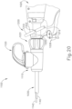
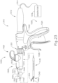
- FIG. 19 shows an exemplary alternative instrument (1010).
- Instrument (1010) of the present example is substantially the same as instrument (10) described above, except as otherwise noted herein.
- Instrument (1010) of the present example comprises a handle assembly (1020), a shaft assembly (1030), and an end effector (1040).
- Handle assembly (1020) comprises a body (1022) including a pistol grip (1024) and a pair of buttons (1026).
- Handle assembly (1020) also includes a trigger (1028) that is pivotable toward and away from pistol grip (1024).
- End effector (1040) includes an ultrasonic blade (1160) and a pivoting clamp arm (1044).
- Clamp arm (1044) is coupled with trigger (1028) such that clamp arm (1044) is pivotable toward ultrasonic blade (1160) in response to pivoting of trigger (1028) toward pistol grip (1024); and such that clamp arm (1044) is pivotable away from ultrasonic blade (1160) in response to pivoting of trigger (1028) away from pistol grip (1024).
- trigger (1028) Various suitable ways in which clamp arm (1044) may be coupled with trigger (1028) will be apparent to those of ordinary skill in the art in view of the teachings herein.
- one or more resilient members are used to bias clamp arm (1044) and/or trigger (1028) to the open position shown in FIG. 1 .
- An ultrasonic transducer assembly (1012) extends proximally from body (1022) of handle assembly (1020).
- Transducer assembly (1012) is coupled with a generator (1016) via a cable (1014), such that transducer assembly (1012) receives electrical power from generator (1016).
- Piezoelectric elements in transducer assembly (1012) convert that electrical power into ultrasonic vibrations.
- Generator (1016) may include a power source and control module that is configured to provide a power profile to transducer assembly (1012) that is particularly suited for the generation of ultrasonic vibrations through transducer assembly (1012).
- Blade (1160) of the present example is operable to vibrate at ultrasonic frequencies in order to effectively cut through and seal tissue.
- Blade (1160) is positioned at the distal end of an acoustic drivetrain.
- This acoustic drivetrain includes transducer assembly (1012) and an acoustic waveguide (not shown).
- the acoustic waveguide comprises a flexible portion (not shown) similar to flexible portion (166) described above with respect to instrument (10).
- Transducer assembly (1012) includes a set of piezoelectric discs (not shown) located proximal to a horn (not shown) of the waveguide.
- the piezoelectric discs are operable to convert electrical power into ultrasonic vibrations, which are then transmitted along the waveguide to blade (1160) in accordance with known configurations and techniques.
- this portion of the acoustic drivetrain may be configured in accordance with various teachings of various references that are cited herein.
- Shaft assembly (1030) of the present example extends distally from handle assembly (1020).
- shaft assembly (1030) is substantially the same as shaft assembly (30) described above with respect to instrument.
- shaft assembly (1030) includes an articulation section (1130), which is located at a distal portion of shaft assembly (1030), with end effector (1040) being located distal to articulation section (1130).
- a knob (1031) is secured to a proximal portion of shaft assembly (1030).
- Knob (1031) is rotatable relative to body (1022), such that shaft assembly (1030) is rotatable about the longitudinal axis defined by shaft assembly (1030), relative to handle assembly (1020). Such rotation may provide rotation of end effector (1040), articulation section (1130), and shaft assembly (1030) unitarily.
- rotatable features may simply be omitted if desired.
- Articulation section (1130) is substantially the same as articulation section (130) described above with respect to instrument (10), unless otherwise note herein.
- articulation section (1130) is operable to selectively position end effector (1040) at various lateral deflection angles relative to a longitudinal axis defined by shaft assembly (1030).
- articulation section (1130) is driven by a pair of articulation bands (1140, 1142) disposed within articulation section (1130) and extending through shaft assembly (1030).
- articulation bands (1140, 1142) translate longitudinally in an opposing fashion, this will cause articulation section (1130) to bend, thereby laterally deflecting end effector (1040) away from the longitudinal axis of shaft assembly (1030) from a straight configuration to an articulated configuration.
- end effector (1040) will be articulated toward the articulation band (1140, 1142) that is being pulled proximally.
- the other articulation band (1140, 1142) may be pulled or pushed distally
- Instrument further includes an articulation control assembly (1100) that is secured to a proximal portion of shaft assembly (1030).
- Articulation control assembly (1100) comprises a housing (1110) and a rotatable knob (1120).
- rotatable knob (1120) is configured to rotate relative to housing (1110) to drive articulation bands (1140, 1142) in opposing longitudinal directions. For instance, rotation of knob (1120) in a first direction causes distal longitudinal translation of articulation band (1140), while simultaneously causing proximal longitudinal translation of articulation band (1142).
- Rotation of knob (1120) in a second direction causes proximal longitudinal translation of articulation band (1140), while simultaneously causing distal longitudinal translation of articulation band (1142).
- rotation of rotation knob (1120) causes articulation of articulation section (1130).
- instrument (1010) of the present example further includes a tensioning assembly (1200).
- Tensioning assembly (1200) is generally operable to translate the entire articulation control assembly (1100) relative to shaft assembly (1030) to thereby simultaneously apply tension to articulation bands (1140, 1142).
- tensioning assembly (1200) comprises a lever arm (1210) and a link (1220).
- Lever arm (1210) is pivotably secured within handle assembly (1020) and is configured to pivot about a pivot point (1212) connecting lever arm (1210) to housing (1020).
- Link (1220) is pivotably connected to lever arm (1210) at a pivot point (1222) connecting link (1220) to lever arm (1210).
- Link (1220) extends from lever arm (1210) through handle assembly (1020) and through knob (1031) where link (1220) pivotably connects to articulation control assembly (1100).
- link (1220) may connect to articulation control assembly (1100) by any suitable means.
- link (1220) is connected to articulation control assembly (1100) by a rotatable collar assembly that is configured to permit articulation control assembly (1100) to rotate relative to link (1220) while still permitting link (1220) to drive translation of articulation control assembly (1100).
- link (1220) may simply be integral with articulation control assembly (1100) or connected with a pin or other securing feature.
- link (1220) may simply be integral with articulation control assembly (1100) or connected with a pin or other securing feature.
- any other suitable mechanisms for connecting link (1220) to articulation control assembly (1100) as will be apparent to those of ordinary skill in the art in view of the teachings herein.
- articulation control assembly (1100) is configured to translate relative to knob (1031) and shaft assembly (1030).
- a proximal portion of housing (1110) is translatably received within knob (1031) to permit some translation of articulation control assembly (1100) relative to knob (1031).
- a spring (1224) is disposed between articulation control assembly (1100) and knob (1031) to resiliently bias articulation control assembly (1100) toward a distal position.
- the distal position of articulation control assembly (1100) corresponds to an articulation position, where articulation bands (1140, 1142) are subjected to low tension, such that articulation control assembly (1100) may cause articulation section (1130) to articulate.
- FIGS. 20 and 22 show an exemplary mode of operation of tensioning assembly (1200).
- FIG. 20 shows tensioning assembly (1200) in an articulation position.
- the articulation position corresponds to articulation bands (1140, 1142) being in a low tension state such that knob (1120) of articulation control assembly (1100) may be used to drive articulation bands (1140, 1142) in opposing directions to articulate articulation section (1130).
- lever arm (1210) is pivoted distally relative to handle assembly (1020). Because link (1220) is attached to lever arm (1210), link (1220) is also positioned distally to thereby permit spring (1224) to drive articulation control assembly (1100) distally.
- An operator may desire to increase the rigidity of articulation section (1130) to thereby lock articulation section (1130) in a particular state of articulation (e.g., straight). To do so, it may be desirable to simultaneously apply tension to both articulation bands (1140, 1142) because such tension may provide opposing forces on articulation section (1130) that work to maintain articulation section (1130) in a given position.
- an operator may grasp lever arm (1210) and pull lever arm (1210) proximally relative to handle assembly (1020).
- tensioning assembly (1200) may include a lock feature or other mechanism to selectively maintain lever arm (1210) in the tensioned position. Where such features are included, an operator may actuate such features after lever arm (1210) is positioned to tension articulation bands (1140, 1142).
- lever arm (1210) and link (1220) may be configured to provide an over-center toggle mechanism, such as the over-center toggle described below.
- locking features may be omitted and lever arm (1210) may simply return to the articulation position once an operator releases lever arm (1210), due to the resilience of spring (1224).
- FIG. 23 shows an exemplary alternative instrument (1310).
- Instrument (1310) of the present example is substantially the same as instrument (10) described above, except as otherwise noted herein.
- Instrument (1310) of the present example comprises a handle assembly (1320), a shaft assembly (1330), and an end effector (1340).
- Handle assembly (1320) comprises a body (1322) including a pistol grip (1324) and a pair of buttons (1326).
- Handle assembly (1320) also includes a trigger (1328) that is pivotable toward and away from pistol grip (1324). It should be understood, however, that various other suitable configurations may be used, including but not limited to a scissor grip configuration.
- End effector (1340) includes an ultrasonic blade (1460) and a pivoting clamp arm (1344).
- Clamp arm (1344) is coupled with trigger (1328) such that clamp arm (1344) is pivotable toward ultrasonic blade (1460) in response to pivoting of trigger (1328) toward pistol grip (1324); and such that clamp arm (1344) is pivotable away from ultrasonic blade (1460) in response to pivoting of trigger (1328) away from pistol grip (1324).
- trigger (1328) Various suitable ways in which clamp arm (1344) may be coupled with trigger (1328) will be apparent to those of ordinary skill in the art in view of the teachings herein.
- one or more resilient members are used to bias clamp arm (1344) and/or trigger (1328) to the open position shown in FIG. 23 .
- An ultrasonic transducer assembly (1312) extends proximally from body (1322) of handle assembly (1320). Transducer assembly (1312) is coupled with a generator (1316) via a cable (1314), such that transducer assembly (1312) receives electrical power from generator (1316). Piezoelectric elements in transducer assembly (1312) convert that electrical power into ultrasonic vibrations.
- Generator (1316) may include a power source and control module that is configured to provide a power profile to transducer assembly (1312) that is particularly suited for the generation of ultrasonic vibrations through transducer assembly (1312).
- Blade (1460) of the present example is operable to vibrate at ultrasonic frequencies in order to effectively cut through and seal tissue.
- Blade (1460) is positioned at the distal end of an acoustic drivetrain.
- This acoustic drivetrain includes transducer assembly (1312) and an acoustic waveguide (not shown).
- the acoustic waveguide comprises a flexible portion (not shown) similar to flexible portion (166) described above with respect to instrument (10).
- Transducer assembly (1312) includes a set of piezoelectric discs (not shown) located proximal to a horn (not shown) of the waveguide.
- the piezoelectric discs are operable to convert electrical power into ultrasonic vibrations, which are then transmitted along the waveguide to blade (1460) in accordance with known configurations and techniques.
- this portion of the acoustic drivetrain may be configured in accordance with various teachings of various references that are cited herein.
- Shaft assembly (1330) of the present example extends distally from handle assembly (1320).
- shaft assembly (1330) is substantially the same as shaft assembly (30) described above with respect to instrument.
- shaft assembly (1330) includes an articulation section (1430), which is located at a distal portion of shaft assembly (1330), with end effector (1340) being located distal to articulation section (1430).
- a knob (1331) is secured to a proximal portion of shaft assembly (1330).
- Knob (1331) is rotatable relative to body (1322), such that shaft assembly (1330) is rotatable about the longitudinal axis defined by shaft assembly (1330), relative to handle assembly (1320).
- Such rotation may provide rotation of end effector (1340), articulation section (1430), and shaft assembly (1330) unitarily.
- rotatable features may simply be omitted if desired.
- Articulation section (1430) is substantially the same as articulation section (130) described above with respect to instrument (10), unless otherwise note herein.
- articulation section (1430) is operable to selectively position end effector (1340) at various lateral deflection angles relative to a longitudinal axis defined by shaft assembly (1430).
- articulation section (1430) is driven by a pair of articulation bands (1440, 1442) disposed within articulation section (1430) and extending through shaft assembly (1330).
- articulation bands (1440, 1142) translate longitudinally in an opposing fashion, this will cause articulation section (1430) to bend, thereby laterally deflecting end effector (1340) away from the longitudinal axis of shaft assembly (1330) from a straight configuration to an articulated configuration.
- end effector (1340) will be articulated toward the articulation band (1440, 1442) that is being pulled proximally.
- the other articulation band (1440, 1442) may be pulled or pushed distally
- Instrument further includes an articulation control assembly (1400) that is secured to a proximal portion of shaft assembly (1330).
- Articulation control assembly (1400) comprises a housing (1410) and a rotatable knob (1420).
- rotatable knob (1420) is configured to rotate relative to housing (1410) to drive articulation bands (1440, 1442) in opposing longitudinal directions. For instance, rotation of knob (1420) in a first direction causes distal longitudinal translation of articulation band (1440), while simultaneously causing proximal longitudinal translation of articulation band (1442).
- Rotation of knob (1420) in a second direction causes proximal longitudinal translation of articulation band (1440), while simultaneously causing distal longitudinal translation of articulation band (1442).
- rotation of rotation knob (1420) causes articulation of articulation section (1430).
- instrument (1310) of the present example further includes a tensioning assembly (1500).
- Tensioning assembly (1500) is generally operable as a over-center toggle mechanism to directly apply tension to articulation bands (1440, 1442) and to maintain such tension.
- tensioning assembly (1500) comprises a lever arm (1510) and a collar (1520) disposed about shaft assembly (1330).
- Lever arm (1510) is attached to housing (1410) of actuation control assembly (1400) at an integral attachment yoke (1415) of housing (1410).
- Lever arm (1510) is connected to attachment yoke (1415) via a pin (1511) that is configured to permit lever arm (1510) to pivot relative to attachment yoke (1415).
- lever arm (1510) is generally configured to pivot relative to attachment yoke (1415) as an over-center toggle mechanism to drive collar (1520) proximally or distally.
- Lever arm (1510) is connected to collar (1520) by two links (1512, 1514) extending between lever arm (1510) and collar (1520).
- Each link (1512, 1514) is pivotably connected to lever arm at a pin (1515) disposed near the center of lever arm (1510).
- Each link (1512, 1514) also pivotably connects to collar (1520) at a respective pivotal coupling (1521, 1522). Both pin (1515) and pivotal couplings (1521, 1522) allow each link to pivot as lever arm (1510) and collar (1520) are moved.
- collar (1520) includes a pair of inwardly extending armatures (1524) (only a single armature is shown) that extend from collar (1520) and into shaft assembly (1330) through a pair of slots (1333) in shaft assembly (1330).
- Each armature (1524) connects to a respective articulation band (1440, 1442).
- each articulation band (1440, 1442) includes a slot that receives a corresponding armature (1524).
- the slots and armatures (1524) are configured such that articulation bands (1440, 1442) may move freely in opposing longitudinal directions when collar (1520) is in the distal position shown in FIG. 26 .
- each armature (1524) is integral or fixedly secured to an inner ring (1526) disposed within collar (1520).
- Inner ring (1526) is configured to freely rotate within collar (1520) while still transferring any translation of collar (1520) to each armature (1524). Such a feature may be desirable because when collar (1520) includes such a feature, collar (1520) may remain stationary while shaft assembly (1330) is rotated.
- collar (1520) may include a cam feature that provides selective engagement between collar (1520) and articulation bands (1440, 1442). For instance, when such a cam feature is in a first position, collar (1520) may be disengaged from articulation bands (1440, 1442), such that articulation bands (1440, 1442) may move freely in opposing longitudinal directions when the cam feature is in the first position. When the cam feature is moved (e.g., rotated, slid, etc.) to a second position, the cam feature may provide engagement between collar (1520) and articulation bands (1440, 1442), such that longitudinal motion of collar (1520) provides corresponding, simultaneous longitudinal motion of articulation bands (1440, 1442).
- Other suitable structures and relationships that may be provided between collar (1520) and articulation bands (1440, 1442) will be apparent to those of ordinary skill in the art in view of the teachings herein.
- tensioning assembly (1500) may initially be in a non-tensioning or relaxed position. In such a position, lever arm (1510) is pivotably disposed upwardly such that pin (1515) is disposed above pin (1511). With lever arm (1510) positioned upwardly, collar (1520) is pushed to a distal position relative to shaft assembly (1330) by each link (1512, 1514). Because collar (1520) is attached to articulation bands (1440, 1442) via armatures (1524), articulation bands (1440, 1442) are in a non-tensioned or relaxed state when collar (1520) is in the distal position. Accordingly, articulation bands (1440, 1442) may be used to articulate articulation section (1430) via articulation control assembly (1400) as described above when collar (1520) is in the distal position.
- an operator may pivot lever arm (1510) downwardly to the position shown in FIG. 27 .
- each link (1512, 1514) pulls collar (1520) proximally relative to shaft assembly (1330).
- collar (1520) is attached to each articulation band (1440, 1442)
- collar (1520) will simultaneously pull each articulation band (1440, 1442) correspondingly proximally.
- collar (1520) will act to apply tension to each articulation band (1440, 1442) as it is pulled proximally by lever arm (1510).
- tensioning assembly (1500) With lever arm (1510) in the position shown in FIG. 27 , tensioning assembly (1500) is in a tensioned position. In the tensioned position, collar (1520) is at its furthest proximal position relative to shaft assembly (1330) and articulation bands (1440, 1442) are correspondingly fully tensioned. Additionally, lever arm (1510) is positioned such that pin (1515) is disposed below pin (1511). Because of this and the tensioning force generated between lever arm (1510) and collar (1520), lever arm (1510) is generally fixed in the tensioned position, such that tensioning assembly (1500) provides an over-center toggle.
- collar (1520) is omitted.
- yoke (1415) is an integral feature of body (1322) of handle assembly (1320), such that lever arm (1510) is pivotably coupled directly to handle assembly (1320).
- the distal ends of links (1512, 1514) are pivotably coupled directly with housing (1410) of articulation control assembly (1400).
- Such an example may operate similar to the example of instrument (1100) described above.
- lever arm (1510) is pivoted to an upward position
- articulation control assembly (1400) is in a distal position and articulation bands (1440, 1442) are free to translate in order to provide articulation of articulation section (1430).
- articulation control assembly (1400) When lever arm (1510) is pivoted to a downward position, articulation control assembly (1400) is in a proximal assembly, pulling articulation bands (1440, 1442) such that articulation bands (1440, 1442) are in tension, thereby effectively rigidizing articulation section (1430) (e.g., when articulation section is in a straight or non-articulated state).
- articulation control assembly (1400) is in a proximal assembly, pulling articulation bands (1440, 1442) such that articulation bands (1440, 1442) are in tension, thereby effectively rigidizing articulation section (1430) (e.g., when articulation section is in a straight or non-articulated state).
- Other suitable variations will be apparent to those of ordinary skill in the art in view of the teachings herein.
- any of the versions of instruments described herein may include various other features in addition to or in lieu of those described above.
- any of the instruments described herein may also include one or more of the various features disclosed in any of the various references disclosed herein.
- teachings herein may be readily applied to any of the instruments described in any of the other references cited herein, such that the teachings herein may be readily combined with the teachings of any of the references cited herein in numerous ways.
- teachings herein may be readily applied to electrosurgical instruments, stapling instruments, and other kinds of surgical instruments.
- Other types of instruments into which the teachings herein may be incorporated will be apparent to those of ordinary skill in the art.
- Versions of the devices described above may have application in conventional medical treatments and procedures conducted by a medical professional, as well as application in robotic-assisted medical treatments and procedures.
- various teachings herein may be readily incorporated into a robotic surgical system such as the DAVINCI TM system by Intuitive Surgical, Inc., of Sunnyvale, California.
- DAVINCI TM system by Intuitive Surgical, Inc., of Sunnyvale, California.
- teachings herein may be readily combined with various teachings of U.S. Pat. No. 6,783,524, entitled "Robotic Surgical Tool with Ultrasound Cauterizing and Cutting Instrument," published August 31, 2004 .
- Versions described above may be designed to be disposed of after a single use, or they can be designed to be used multiple times. Versions may, in either or both cases, be reconditioned for reuse after at least one use. Reconditioning may include any combination of the steps of disassembly of the device, followed by cleaning or replacement of particular pieces, and subsequent reassembly. In particular, some versions of the device may be disassembled, and any number of the particular pieces or parts of the device may be selectively replaced or removed in any combination. Upon cleaning and/or replacement of particular parts, some versions of the device may be reassembled for subsequent use either at a reconditioning facility, or by a user immediately prior to a procedure.
- reconditioning of a device may utilize a variety of techniques for disassembly, cleaning/replacement, and reassembly. Use of such techniques, and the resulting reconditioned device, are all within the scope of the present application.
- versions described herein may be sterilized before and/or after a procedure.
- the device is placed in a closed and sealed container, such as a plastic or TYVEK bag.
- the container and device may then be placed in a field of radiation that can penetrate the container, such as gamma radiation, x-rays, or high-energy electrons.
- the radiation may kill bacteria on the device and in the container.
- the sterilized device may then be stored in the sterile container for later use.
- a device may also be sterilized using any other technique known in the art, including but not limited to beta or gamma radiation, ethylene oxide, or steam.
Landscapes
- Health & Medical Sciences (AREA)
- Life Sciences & Earth Sciences (AREA)
- Surgery (AREA)
- Engineering & Computer Science (AREA)
- Medical Informatics (AREA)
- Nuclear Medicine, Radiotherapy & Molecular Imaging (AREA)
- Biomedical Technology (AREA)
- Heart & Thoracic Surgery (AREA)
- Molecular Biology (AREA)
- Animal Behavior & Ethology (AREA)
- General Health & Medical Sciences (AREA)
- Public Health (AREA)
- Veterinary Medicine (AREA)
- Ophthalmology & Optometry (AREA)
- Surgical Instruments (AREA)
- Dentistry (AREA)
- Mechanical Engineering (AREA)
Claims (12)
- Appareil (10) permettant d'opérer sur des tissus, l'appareil comprenant :(a) un ensemble corps (11) ;(b) une tige (30) s'étendant distalement à partir de l'ensemble corps, dans lequel la tige définit un axe longitudinal ;(c) un guide d'ondes acoustiques (180), dans lequel le guide d'ondes comprend une partie flexible (166) ;(d) une section d'articulation (130) couplée à la tige, dans lequel une partie de la section d'articulation (130) englobe la partie flexible (166) du guide d'ondes, dans lequel la section d'articulation comprend en outre :(i) un premier élément (140), et(ii) un second élément (142), dans lequel le second élément (142) peut être déplacé longitudinalement par rapport au premier élément (140) ;(e) un effecteur terminal (40) comprenant une lame ultrasonique (160) en communication acoustique avec le guide d'ondes ; et caractérisé par :(f) un verrou d'articulation (200, 300, 1200, 1500), dans lequel le verrou d'articulation comprend un dispositif de tension (220, 320, 1210, 1520), dans lequel le dispositif de tension est conçu pour appliquer sélectivement une tension à au moins un du premier élément (140) et du second élément (142) de la section d'articulation afin d'augmenter la rigidité de la section d'articulation.
- Appareil selon la revendication 1, dans lequel le dispositif de tension (220, 320, 1210, 1520) du verrou d'articulation est conçu pour appliquer sélectivement une tension au premier élément (140) et au second élément (142) de la section d'articulation.
- Appareil selon la revendication 2, comprenant en outre un ensemble de commande de l'articulation en communication avec le premier élément (140) et le second élément (142) de la section d'articulation (130).
- Appareil selon la revendication 3, dans lequel le dispositif de tension (220, 320, 1520) du verrou d'articulation est conçu pour entraîner l'ensemble de commande d'articulation de manière proximale afin d'appliquer une tension au premier élément (140) et au second élément (142) de la section d'articulation.
- Appareil selon la revendication 3, dans lequel l'ensemble de commande de l'articulation comprend un bouton, dans lequel le bouton est conçu pour tourner afin d'entraîner le premier élément (140) et le second élément (142) de la section d'articulation dans des directions opposées.
- Appareil selon la revendication 5, dans lequel le bouton est conçu pour se déplacer afin d'entraîner simultanément le premier élément (140) et le second élément (142) de la section d'articulation (130) dans la même direction, et éventuellement dans lequel le dispositif de tension comprend deux éléments chanfreinés s'étendant à partir du bouton, dans lequel les éléments chanfreinés sont opérationnels pour appliquer une tension au premier élément (140) et au second élément de la section d'articulation (130).
- Appareil selon la revendication 5, dans lequel le bouton est conçu pour pivoter afin d'entraîner le premier élément (140) et le second élément (142) de la section d'articulation (130) dans la même direction, dans lequel la caractéristique de tension du verrou d'articulation (200, 300, 1200, 1500) comprend deux goupilles s'étendant à partir du bouton.
- Appareil selon la revendication 1, dans lequel le verrou d'articulation (200, 300, 1200, 1500) comprend au moins deux segments asymétriques (430) disposés l'un à côté de l'autre sur la section d'articulation.
- Appareil selon la revendication 8, dans lequel chaque segment asymétrique (430) comprend une partie d'articulation (435) et une partie de verrouillage (437), dans laquelle la partie d'articulation comprend un chanfrein (436), dans lequel la partie de verrouillage (437) est droite par rapport au chanfrein de la partie d'articulation.
- Appareil selon la revendication 9, dans lequel le premier élément (140) est adjacent à la partie d'articulation (435), dans lequel le second élément (142) est adjacent à la partie de verrouillage (437), dans lequel le dispositif de tension est conçu pour appliquer sélectivement une tension au premier élément (140) afin d'articuler la section d'articulation dans la direction de la partie d'articulation de chaque segment asymétrique, et éventuellement dans lequel
le dispositif de tension est conçu pour appliquer sélectivement une tension au second élément afin de rendre la section d'articulation rigide en mettant en contact les parties de verrouillage de chaque lien asymétrique avec les autres segments asymétriques adjacents. - Appareil selon la revendication 1, dans lequel le verrou d'articulation comprend en outre un levier (1510), dans lequel le dispositif de tension comprend un collier (1520) disposé autour d'au moins une partie de la tige, dans lequel le levier est en communication avec le collier (1520) par l'intermédiaire d'au moins un lien.
- Appareil selon la revendication 11, comprenant soit l'option a), soit les options a) et b) des options a) et b) suivantes :a) dans lequel le levier (1510) comprend une première armature et une seconde armature (1524) s'étendant dans la tige à partir du collier (1520), la première armature étant fixée au premier élément (140) de la section d'articulation, dans lequel la seconde armature est fixée au second élément (142) de la section d'articulation ; etb) dans lequel le levier (1510) est conçu pour déplacer le collier (1520) par rapport à la tige jusqu'à une position de tension, dans lequel le collier (1520) est conçu pour appliquer une tension aux premier (140) et second (142) éléments de la section d'articulation lorsque le collier (1520) est disposé dans la position de tension, et éventuellement dans lequel le levier comprend un mécanisme de basculement en sur-centre.
Applications Claiming Priority (2)
| Application Number | Priority Date | Filing Date | Title |
|---|---|---|---|
| US14/688,458 US10034683B2 (en) | 2015-04-16 | 2015-04-16 | Ultrasonic surgical instrument with rigidizing articulation drive members |
| PCT/US2016/027680 WO2016168546A1 (fr) | 2015-04-16 | 2016-04-15 | Instrument chirurgical à ultrasons comportant des éléments d'entraînement de l'articulation raidisseurs |
Publications (2)
| Publication Number | Publication Date |
|---|---|
| EP3282965A1 EP3282965A1 (fr) | 2018-02-21 |
| EP3282965B1 true EP3282965B1 (fr) | 2024-11-06 |
Family
ID=55806884
Family Applications (1)
| Application Number | Title | Priority Date | Filing Date |
|---|---|---|---|
| EP16718180.9A Active EP3282965B1 (fr) | 2015-04-16 | 2016-04-15 | Instrument chirurgical à ultrasons comportant des éléments d'entraînement d'une articulation pouvant la rigidifier |
Country Status (7)
| Country | Link |
|---|---|
| US (1) | US10034683B2 (fr) |
| EP (1) | EP3282965B1 (fr) |
| JP (1) | JP6732792B2 (fr) |
| CN (1) | CN107530099B (fr) |
| BR (1) | BR112017022071B1 (fr) |
| MX (1) | MX388649B (fr) |
| WO (1) | WO2016168546A1 (fr) |
Families Citing this family (31)
| Publication number | Priority date | Publication date | Assignee | Title |
|---|---|---|---|---|
| US10258363B2 (en) | 2014-04-22 | 2019-04-16 | Ethicon Llc | Method of operating an articulating ultrasonic surgical instrument |
| US10667835B2 (en) | 2014-04-22 | 2020-06-02 | Ethicon Llc | Ultrasonic surgical instrument with end effector having restricted articulation |
| US10413316B2 (en) | 2015-11-17 | 2019-09-17 | Covidien Lp | Articulating ultrasonic surgical instruments and systems |
| US10743850B2 (en) | 2016-04-04 | 2020-08-18 | Ethicon Llc | Surgical instrument with locking articulation drive wheel |
| US10507034B2 (en) | 2016-04-04 | 2019-12-17 | Ethicon Llc | Surgical instrument with motorized articulation drive in shaft rotation knob |
| US10405876B2 (en) | 2016-04-05 | 2019-09-10 | Ethicon Llc | Articulation joint for surgical instrument |
| EP3530197B1 (fr) * | 2016-11-10 | 2024-04-03 | Reach Surgical, Inc. | Instrument chirurgical ayant une fonction d'interverrouillage |
| WO2018160401A1 (fr) * | 2017-02-28 | 2018-09-07 | Boston Scientific Scimed, Inc. | Aiguilles articulées |
| US10925630B2 (en) | 2018-06-19 | 2021-02-23 | Ethicon Llc | Surgical devices and systems with rotating end effector assemblies having an ultrasonic blade |
| US11033293B2 (en) | 2017-07-19 | 2021-06-15 | Cilag Gmbh International | Ultrasonic transducer to blade acoustic coupling, connections, and configurations |
| US10582945B2 (en) | 2018-03-20 | 2020-03-10 | Ethicon Llc | Surgical devices and systems with rotating end effector assemblies having an ultrasonic blade |
| CN109662740B (zh) * | 2018-04-02 | 2021-04-16 | 成都五义医疗科技有限公司 | 一种手术器械 |
| US11457945B2 (en) | 2019-08-30 | 2022-10-04 | Cilag Gmbh International | Ultrasonic blade and clamp arm alignment features |
| EP4021318B1 (fr) | 2019-08-30 | 2025-07-02 | Cilag GmbH International | Instrument chirurgical à ultrasons avec un ensemble arbre articulé dans des plans multiples |
| US11690642B2 (en) | 2019-08-30 | 2023-07-04 | Cilag Gmbh International | Ultrasonic surgical instrument with a multi-planar articulating shaft assembly |
| US11712261B2 (en) | 2019-08-30 | 2023-08-01 | Cilag Gmbh International | Rotatable linear actuation mechanism |
| US11612409B2 (en) | 2019-08-30 | 2023-03-28 | Cilag Gmbh International | Ultrasonic transducer alignment of an articulating ultrasonic surgical instrument |
| US11471181B2 (en) | 2019-08-30 | 2022-10-18 | Cilag Gmbh International | Ultrasonic surgical instrument with axisymmetric clamping |
| US11857283B2 (en) | 2019-11-05 | 2024-01-02 | Cilag Gmbh International | Articulation joint with helical lumen |
| WO2021119616A1 (fr) * | 2019-12-12 | 2021-06-17 | Stryker Corporation | Commande d'une pièce à main ultrasonore |
| EP4114287B1 (fr) | 2020-03-02 | 2025-12-17 | Covidien LP | Instruments chirurgicaux à ultrasons articulés et systèmes |
| EP4149375B1 (fr) | 2020-05-15 | 2025-01-08 | Covidien LP | Instruments chirurgicaux à ultrasons articulés et systèmes |
| US11766275B2 (en) | 2020-05-18 | 2023-09-26 | Covidien Lp | Articulating ultrasonic surgical instruments and systems |
| US12161355B2 (en) | 2020-05-18 | 2024-12-10 | Covidien Lp | Articulating ultrasonic surgical instruments and systems |
| US11911064B2 (en) | 2020-12-21 | 2024-02-27 | Cilag Gmbh International | Ultrasonic surgical instrument with a clamp arm clocking assembly |
| KR102559600B1 (ko) * | 2021-04-06 | 2023-07-25 | 주식회사 로엔서지컬 | 수술도구의 비대칭 구름 관절 장치 |
| CN117295460A (zh) | 2021-05-13 | 2023-12-26 | 柯惠有限合伙公司 | 纳入了偏移式末端执行器的手术器械和系统 |
| US12569271B2 (en) | 2021-06-11 | 2026-03-10 | Covidien Lp | Surgical instruments, systems, and methods incorporating an ultrasonic transducer |
| US20230355266A1 (en) | 2022-05-05 | 2023-11-09 | Cilag Gmbh International | Clamp force control feature for surgical end effector |
| US20240366255A1 (en) | 2023-05-04 | 2024-11-07 | Cilag Gmbh International | Distal node grounding features for acoustic waveguide |
| US20250375214A1 (en) | 2024-06-07 | 2025-12-11 | Cilag Gmbh International | Ultrasonic surgical instrument and method of laterally aligning blade with clamp arm |
Family Cites Families (39)
| Publication number | Priority date | Publication date | Assignee | Title |
|---|---|---|---|---|
| US5147380A (en) * | 1991-10-03 | 1992-09-15 | Cordis Corporation | Biopsy forceps device having improved locking means |
| US5322055B1 (en) | 1993-01-27 | 1997-10-14 | Ultracision Inc | Clamp coagulator/cutting system for ultrasonic surgical instruments |
| US5766196A (en) * | 1994-06-06 | 1998-06-16 | Tnco, Inc. | Surgical instrument with steerable distal end |
| US5704534A (en) * | 1994-12-19 | 1998-01-06 | Ethicon Endo-Surgery, Inc. | Articulation assembly for surgical instruments |
| US6063098A (en) | 1996-12-23 | 2000-05-16 | Houser; Kevin | Articulable ultrasonic surgical apparatus |
| US5873873A (en) | 1997-10-10 | 1999-02-23 | Ethicon Endo-Surgery, Inc. | Ultrasonic clamp coagulator apparatus having improved clamp mechanism |
| US5980510A (en) | 1997-10-10 | 1999-11-09 | Ethicon Endo-Surgery, Inc. | Ultrasonic clamp coagulator apparatus having improved clamp arm pivot mount |
| US6589200B1 (en) | 1999-02-22 | 2003-07-08 | Ethicon Endo-Surgery, Inc. | Articulating ultrasonic surgical shears |
| US5897523A (en) | 1998-04-13 | 1999-04-27 | Ethicon Endo-Surgery, Inc. | Articulating ultrasonic surgical instrument |
| US6454782B1 (en) | 1998-04-13 | 2002-09-24 | Ethicon Endo-Surgery, Inc. | Actuation mechanism for surgical instruments |
| US5989264A (en) | 1998-06-11 | 1999-11-23 | Ethicon Endo-Surgery, Inc. | Ultrasonic polyp snare |
| US6325811B1 (en) | 1999-10-05 | 2001-12-04 | Ethicon Endo-Surgery, Inc. | Blades with functional balance asymmetries for use with ultrasonic surgical instruments |
| US6752815B2 (en) | 2001-01-31 | 2004-06-22 | Ethicon Endo-Surgery, Inc. | Method and waveguides for changing the direction of longitudinal vibrations |
| US6783524B2 (en) | 2001-04-19 | 2004-08-31 | Intuitive Surgical, Inc. | Robotic surgical tool with ultrasound cauterizing and cutting instrument |
| US6817974B2 (en) * | 2001-06-29 | 2004-11-16 | Intuitive Surgical, Inc. | Surgical tool having positively positionable tendon-actuated multi-disk wrist joint |
| US8100824B2 (en) | 2003-05-23 | 2012-01-24 | Intuitive Surgical Operations, Inc. | Tool with articulation lock |
| US7410483B2 (en) * | 2003-05-23 | 2008-08-12 | Novare Surgical Systems, Inc. | Hand-actuated device for remote manipulation of a grasping tool |
| JP4578850B2 (ja) * | 2004-04-19 | 2010-11-10 | オリンパス株式会社 | 超音波処置具 |
| US7828808B2 (en) * | 2004-06-07 | 2010-11-09 | Novare Surgical Systems, Inc. | Link systems and articulation mechanisms for remote manipulation of surgical or diagnostic tools |
| JP5009159B2 (ja) | 2004-10-08 | 2012-08-22 | エシコン・エンド−サージェリィ・インコーポレイテッド | 超音波手術器具 |
| US20060178562A1 (en) * | 2005-02-10 | 2006-08-10 | Usgi Medical Inc. | Apparatus and methods for obtaining endoluminal access with a steerable guide having a variable pivot |
| US20070191713A1 (en) | 2005-10-14 | 2007-08-16 | Eichmann Stephen E | Ultrasonic device for cutting and coagulating |
| US7621930B2 (en) | 2006-01-20 | 2009-11-24 | Ethicon Endo-Surgery, Inc. | Ultrasound medical instrument having a medical ultrasonic blade |
| WO2007089676A1 (fr) | 2006-01-27 | 2007-08-09 | Medtronic, Inc. | Appareil et système de dissection chirurgicale et/ou de guidage d'autres appareils médicaux dans un corps |
| US8105350B2 (en) | 2006-05-23 | 2012-01-31 | Cambridge Endoscopic Devices, Inc. | Surgical instrument |
| US8366727B2 (en) | 2006-06-01 | 2013-02-05 | Ethicon Endo-Surgery, Inc. | Tissue pad ultrasonic surgical instrument |
| AU2008206385B2 (en) | 2007-01-16 | 2013-10-24 | Ethicon Endo-Surgery, Inc. | Ultrasonic device for cutting and coagulating |
| US8057498B2 (en) | 2007-11-30 | 2011-11-15 | Ethicon Endo-Surgery, Inc. | Ultrasonic surgical instrument blades |
| CN101883531B (zh) | 2007-10-05 | 2014-07-02 | 伊西康内外科公司 | 人体工程学外科手术器械 |
| WO2010030850A2 (fr) | 2008-09-12 | 2010-03-18 | Ethicon Endo-Surgery, Inc. | Dispositif à ultrasons à commande tactile |
| US8461744B2 (en) | 2009-07-15 | 2013-06-11 | Ethicon Endo-Surgery, Inc. | Rotating transducer mount for ultrasonic surgical instruments |
| US9060775B2 (en) | 2009-10-09 | 2015-06-23 | Ethicon Endo-Surgery, Inc. | Surgical generator for ultrasonic and electrosurgical devices |
| US9402682B2 (en) | 2010-09-24 | 2016-08-02 | Ethicon Endo-Surgery, Llc | Articulation joint features for articulating surgical device |
| US20120116265A1 (en) | 2010-11-05 | 2012-05-10 | Houser Kevin L | Surgical instrument with charging devices |
| US9381058B2 (en) | 2010-11-05 | 2016-07-05 | Ethicon Endo-Surgery, Llc | Recharge system for medical devices |
| US9408622B2 (en) | 2012-06-29 | 2016-08-09 | Ethicon Endo-Surgery, Llc | Surgical instruments with articulating shafts |
| US9393037B2 (en) | 2012-06-29 | 2016-07-19 | Ethicon Endo-Surgery, Llc | Surgical instruments with articulating shafts |
| US9095367B2 (en) | 2012-10-22 | 2015-08-04 | Ethicon Endo-Surgery, Inc. | Flexible harmonic waveguides/blades for surgical instruments |
| US10172636B2 (en) | 2013-09-17 | 2019-01-08 | Ethicon Llc | Articulation features for ultrasonic surgical instrument |
-
2015
- 2015-04-16 US US14/688,458 patent/US10034683B2/en active Active
-
2016
- 2016-04-15 MX MX2017013272A patent/MX388649B/es unknown
- 2016-04-15 JP JP2017553968A patent/JP6732792B2/ja active Active
- 2016-04-15 EP EP16718180.9A patent/EP3282965B1/fr active Active
- 2016-04-15 BR BR112017022071-7A patent/BR112017022071B1/pt active IP Right Grant
- 2016-04-15 WO PCT/US2016/027680 patent/WO2016168546A1/fr not_active Ceased
- 2016-04-15 CN CN201680021951.4A patent/CN107530099B/zh active Active
Also Published As
| Publication number | Publication date |
|---|---|
| CN107530099B (zh) | 2021-03-02 |
| JP6732792B2 (ja) | 2020-07-29 |
| CN107530099A (zh) | 2018-01-02 |
| US10034683B2 (en) | 2018-07-31 |
| MX388649B (es) | 2025-03-20 |
| US20160302812A1 (en) | 2016-10-20 |
| MX2017013272A (es) | 2018-01-26 |
| BR112017022071B1 (pt) | 2022-05-17 |
| JP2018511428A (ja) | 2018-04-26 |
| EP3282965A1 (fr) | 2018-02-21 |
| BR112017022071A2 (pt) | 2018-07-03 |
| WO2016168546A1 (fr) | 2016-10-20 |
Similar Documents
| Publication | Publication Date | Title |
|---|---|---|
| US12178464B2 (en) | Ultrasonic surgical instrument with articulating end effector having a curved blade | |
| US10034683B2 (en) | Ultrasonic surgical instrument with rigidizing articulation drive members | |
| US12383294B2 (en) | Articulation joint for surgical instrument | |
| US12318079B2 (en) | Surgical instrument with locking articulation drive wheel | |
| US12414794B2 (en) | Surgical instrument with dual mode articulation drive | |
| EP3744267B1 (fr) | Instrument chirurgical doté d'un ensemble d'articulation à verrouillage sélectif | |
| EP3282966B1 (fr) | Instrument chirurgical à ultrasons avec élément raidisseur mobile | |
| CA2946726C (fr) | Instrument chirurgical a ultrasons ayant un effecteur final ayant une articulation restreinte | |
| EP3673842A1 (fr) | Instrument chirurgical ultrasonore présentant un entraînement d'articulation motorisé dans un bouton de rotation d'arbre |
Legal Events
| Date | Code | Title | Description |
|---|---|---|---|
| STAA | Information on the status of an ep patent application or granted ep patent |
Free format text: STATUS: THE INTERNATIONAL PUBLICATION HAS BEEN MADE |
|
| PUAI | Public reference made under article 153(3) epc to a published international application that has entered the european phase |
Free format text: ORIGINAL CODE: 0009012 |
|
| STAA | Information on the status of an ep patent application or granted ep patent |
Free format text: STATUS: REQUEST FOR EXAMINATION WAS MADE |
|
| 17P | Request for examination filed |
Effective date: 20171113 |
|
| AK | Designated contracting states |
Kind code of ref document: A1 Designated state(s): AL AT BE BG CH CY CZ DE DK EE ES FI FR GB GR HR HU IE IS IT LI LT LU LV MC MK MT NL NO PL PT RO RS SE SI SK SM TR |
|
| AX | Request for extension of the european patent |
Extension state: BA ME |
|
| STAA | Information on the status of an ep patent application or granted ep patent |
Free format text: STATUS: EXAMINATION IS IN PROGRESS |
|
| 17Q | First examination report despatched |
Effective date: 20210203 |
|
| GRAP | Despatch of communication of intention to grant a patent |
Free format text: ORIGINAL CODE: EPIDOSNIGR1 |
|
| STAA | Information on the status of an ep patent application or granted ep patent |
Free format text: STATUS: GRANT OF PATENT IS INTENDED |
|
| INTG | Intention to grant announced |
Effective date: 20240529 |
|
| RIN1 | Information on inventor provided before grant (corrected) |
Inventor name: SHAPIRO, CARA L. Inventor name: ASHER, RYAN M. Inventor name: DICKERSON, BENJAMIN D. Inventor name: SCHULTE, JOHN B. Inventor name: MESSERLY, JEFFREY D. Inventor name: GEE, JACOB S. Inventor name: PIROZZI, KRISTEN L. Inventor name: FALLER, CRAIG N. Inventor name: TIMM, RICHARD W. Inventor name: MONROE, DAVID A. |
|
| GRAS | Grant fee paid |
Free format text: ORIGINAL CODE: EPIDOSNIGR3 |
|
| GRAA | (expected) grant |
Free format text: ORIGINAL CODE: 0009210 |
|
| STAA | Information on the status of an ep patent application or granted ep patent |
Free format text: STATUS: THE PATENT HAS BEEN GRANTED |
|
| AK | Designated contracting states |
Kind code of ref document: B1 Designated state(s): AL AT BE BG CH CY CZ DE DK EE ES FI FR GB GR HR HU IE IS IT LI LT LU LV MC MK MT NL NO PL PT RO RS SE SI SK SM TR |
|
| REG | Reference to a national code |
Ref country code: GB Ref legal event code: FG4D |
|
| REG | Reference to a national code |
Ref country code: CH Ref legal event code: EP |
|
| REG | Reference to a national code |
Ref country code: DE Ref legal event code: R096 Ref document number: 602016090119 Country of ref document: DE |
|
| REG | Reference to a national code |
Ref country code: IE Ref legal event code: FG4D |
|
| REG | Reference to a national code |
Ref country code: LT Ref legal event code: MG9D |
|
| REG | Reference to a national code |
Ref country code: NL Ref legal event code: MP Effective date: 20241106 |
|
| PG25 | Lapsed in a contracting state [announced via postgrant information from national office to epo] |
Ref country code: PT Free format text: LAPSE BECAUSE OF FAILURE TO SUBMIT A TRANSLATION OF THE DESCRIPTION OR TO PAY THE FEE WITHIN THE PRESCRIBED TIME-LIMIT Effective date: 20250306 Ref country code: IS Free format text: LAPSE BECAUSE OF FAILURE TO SUBMIT A TRANSLATION OF THE DESCRIPTION OR TO PAY THE FEE WITHIN THE PRESCRIBED TIME-LIMIT Effective date: 20250306 Ref country code: HR Free format text: LAPSE BECAUSE OF FAILURE TO SUBMIT A TRANSLATION OF THE DESCRIPTION OR TO PAY THE FEE WITHIN THE PRESCRIBED TIME-LIMIT Effective date: 20241106 |
|
| PG25 | Lapsed in a contracting state [announced via postgrant information from national office to epo] |
Ref country code: FI Free format text: LAPSE BECAUSE OF FAILURE TO SUBMIT A TRANSLATION OF THE DESCRIPTION OR TO PAY THE FEE WITHIN THE PRESCRIBED TIME-LIMIT Effective date: 20241106 Ref country code: NL Free format text: LAPSE BECAUSE OF FAILURE TO SUBMIT A TRANSLATION OF THE DESCRIPTION OR TO PAY THE FEE WITHIN THE PRESCRIBED TIME-LIMIT Effective date: 20241106 |
|
| REG | Reference to a national code |
Ref country code: AT Ref legal event code: MK05 Ref document number: 1738507 Country of ref document: AT Kind code of ref document: T Effective date: 20241106 |
|
| PG25 | Lapsed in a contracting state [announced via postgrant information from national office to epo] |
Ref country code: BG Free format text: LAPSE BECAUSE OF FAILURE TO SUBMIT A TRANSLATION OF THE DESCRIPTION OR TO PAY THE FEE WITHIN THE PRESCRIBED TIME-LIMIT Effective date: 20241106 |
|
| PG25 | Lapsed in a contracting state [announced via postgrant information from national office to epo] |
Ref country code: ES Free format text: LAPSE BECAUSE OF FAILURE TO SUBMIT A TRANSLATION OF THE DESCRIPTION OR TO PAY THE FEE WITHIN THE PRESCRIBED TIME-LIMIT Effective date: 20241106 |
|
| PG25 | Lapsed in a contracting state [announced via postgrant information from national office to epo] |
Ref country code: NO Free format text: LAPSE BECAUSE OF FAILURE TO SUBMIT A TRANSLATION OF THE DESCRIPTION OR TO PAY THE FEE WITHIN THE PRESCRIBED TIME-LIMIT Effective date: 20250206 |
|
| PG25 | Lapsed in a contracting state [announced via postgrant information from national office to epo] |
Ref country code: AT Free format text: LAPSE BECAUSE OF FAILURE TO SUBMIT A TRANSLATION OF THE DESCRIPTION OR TO PAY THE FEE WITHIN THE PRESCRIBED TIME-LIMIT Effective date: 20241106 Ref country code: LV Free format text: LAPSE BECAUSE OF FAILURE TO SUBMIT A TRANSLATION OF THE DESCRIPTION OR TO PAY THE FEE WITHIN THE PRESCRIBED TIME-LIMIT Effective date: 20241106 Ref country code: GR Free format text: LAPSE BECAUSE OF FAILURE TO SUBMIT A TRANSLATION OF THE DESCRIPTION OR TO PAY THE FEE WITHIN THE PRESCRIBED TIME-LIMIT Effective date: 20250207 |
|
| PG25 | Lapsed in a contracting state [announced via postgrant information from national office to epo] |
Ref country code: PL Free format text: LAPSE BECAUSE OF FAILURE TO SUBMIT A TRANSLATION OF THE DESCRIPTION OR TO PAY THE FEE WITHIN THE PRESCRIBED TIME-LIMIT Effective date: 20241106 |
|
| PG25 | Lapsed in a contracting state [announced via postgrant information from national office to epo] |
Ref country code: RS Free format text: LAPSE BECAUSE OF FAILURE TO SUBMIT A TRANSLATION OF THE DESCRIPTION OR TO PAY THE FEE WITHIN THE PRESCRIBED TIME-LIMIT Effective date: 20250206 |
|
| PG25 | Lapsed in a contracting state [announced via postgrant information from national office to epo] |
Ref country code: SM Free format text: LAPSE BECAUSE OF FAILURE TO SUBMIT A TRANSLATION OF THE DESCRIPTION OR TO PAY THE FEE WITHIN THE PRESCRIBED TIME-LIMIT Effective date: 20241106 |
|
| PG25 | Lapsed in a contracting state [announced via postgrant information from national office to epo] |
Ref country code: DK Free format text: LAPSE BECAUSE OF FAILURE TO SUBMIT A TRANSLATION OF THE DESCRIPTION OR TO PAY THE FEE WITHIN THE PRESCRIBED TIME-LIMIT Effective date: 20241106 |
|
| VS25 | Lapsed in a validation state [announced via postgrant information from nat. office to epo] |
Ref country code: MD Free format text: LAPSE BECAUSE OF FAILURE TO SUBMIT A TRANSLATION OF THE DESCRIPTION OR TO PAY THE FEE WITHIN THE PRESCRIBED TIME-LIMIT Effective date: 20241106 |
|
| PG25 | Lapsed in a contracting state [announced via postgrant information from national office to epo] |
Ref country code: EE Free format text: LAPSE BECAUSE OF FAILURE TO SUBMIT A TRANSLATION OF THE DESCRIPTION OR TO PAY THE FEE WITHIN THE PRESCRIBED TIME-LIMIT Effective date: 20241106 |
|
| PG25 | Lapsed in a contracting state [announced via postgrant information from national office to epo] |
Ref country code: RO Free format text: LAPSE BECAUSE OF FAILURE TO SUBMIT A TRANSLATION OF THE DESCRIPTION OR TO PAY THE FEE WITHIN THE PRESCRIBED TIME-LIMIT Effective date: 20241106 |
|
| PG25 | Lapsed in a contracting state [announced via postgrant information from national office to epo] |
Ref country code: SK Free format text: LAPSE BECAUSE OF FAILURE TO SUBMIT A TRANSLATION OF THE DESCRIPTION OR TO PAY THE FEE WITHIN THE PRESCRIBED TIME-LIMIT Effective date: 20241106 |
|
| PG25 | Lapsed in a contracting state [announced via postgrant information from national office to epo] |
Ref country code: CZ Free format text: LAPSE BECAUSE OF FAILURE TO SUBMIT A TRANSLATION OF THE DESCRIPTION OR TO PAY THE FEE WITHIN THE PRESCRIBED TIME-LIMIT Effective date: 20241106 |
|
| PG25 | Lapsed in a contracting state [announced via postgrant information from national office to epo] |
Ref country code: IT Free format text: LAPSE BECAUSE OF FAILURE TO SUBMIT A TRANSLATION OF THE DESCRIPTION OR TO PAY THE FEE WITHIN THE PRESCRIBED TIME-LIMIT Effective date: 20241106 |
|
| REG | Reference to a national code |
Ref country code: DE Ref legal event code: R097 Ref document number: 602016090119 Country of ref document: DE |
|
| PG25 | Lapsed in a contracting state [announced via postgrant information from national office to epo] |
Ref country code: SE Free format text: LAPSE BECAUSE OF FAILURE TO SUBMIT A TRANSLATION OF THE DESCRIPTION OR TO PAY THE FEE WITHIN THE PRESCRIBED TIME-LIMIT Effective date: 20241106 |
|
| PLBE | No opposition filed within time limit |
Free format text: ORIGINAL CODE: 0009261 |
|
| STAA | Information on the status of an ep patent application or granted ep patent |
Free format text: STATUS: NO OPPOSITION FILED WITHIN TIME LIMIT |
|
| 26N | No opposition filed |
Effective date: 20250807 |
|
| REG | Reference to a national code |
Ref country code: DE Ref legal event code: R119 Ref document number: 602016090119 Country of ref document: DE |
|
| REG | Reference to a national code |
Ref country code: CH Ref legal event code: H13 Free format text: ST27 STATUS EVENT CODE: U-0-0-H10-H13 (AS PROVIDED BY THE NATIONAL OFFICE) Effective date: 20251125 |
|
| PG25 | Lapsed in a contracting state [announced via postgrant information from national office to epo] |
Ref country code: LU Free format text: LAPSE BECAUSE OF NON-PAYMENT OF DUE FEES Effective date: 20250415 |
|
| PG25 | Lapsed in a contracting state [announced via postgrant information from national office to epo] |
Ref country code: MC Free format text: LAPSE BECAUSE OF FAILURE TO SUBMIT A TRANSLATION OF THE DESCRIPTION OR TO PAY THE FEE WITHIN THE PRESCRIBED TIME-LIMIT Effective date: 20241106 |
|
| GBPC | Gb: european patent ceased through non-payment of renewal fee |
Effective date: 20250415 |
|
| REG | Reference to a national code |
Ref country code: BE Ref legal event code: MM Effective date: 20250430 |
|
| PG25 | Lapsed in a contracting state [announced via postgrant information from national office to epo] |
Ref country code: DE Free format text: LAPSE BECAUSE OF NON-PAYMENT OF DUE FEES Effective date: 20251104 |
|
| PG25 | Lapsed in a contracting state [announced via postgrant information from national office to epo] |
Ref country code: GB Free format text: LAPSE BECAUSE OF NON-PAYMENT OF DUE FEES Effective date: 20250415 |
|
| PG25 | Lapsed in a contracting state [announced via postgrant information from national office to epo] |
Ref country code: FR Free format text: LAPSE BECAUSE OF NON-PAYMENT OF DUE FEES Effective date: 20250430 |
|
| PG25 | Lapsed in a contracting state [announced via postgrant information from national office to epo] |
Ref country code: BE Free format text: LAPSE BECAUSE OF NON-PAYMENT OF DUE FEES Effective date: 20250430 |
|
| PG25 | Lapsed in a contracting state [announced via postgrant information from national office to epo] |
Ref country code: CH Free format text: LAPSE BECAUSE OF NON-PAYMENT OF DUE FEES Effective date: 20250430 |
|
| VS25 | Lapsed in a validation state [announced via postgrant information from nat. office to epo] |
Ref country code: MA Free format text: FAILURE TO ELECT DOMICILE IN THE NATIONAL COUNTRY Effective date: 20250207 |
|
| VS25 | Lapsed in a validation state [announced via postgrant information from nat. office to epo] |
Ref country code: MA Free format text: LAPSE BECAUSE OF FAILURE TO SUBMIT A TRANSLATION OF THE DESCRIPTION OR TO PAY THE FEE WITHIN THE PRESCRIBED TIME-LIMIT Effective date: 20241106 |
|
| PG25 | Lapsed in a contracting state [announced via postgrant information from national office to epo] |
Ref country code: IE Free format text: LAPSE BECAUSE OF NON-PAYMENT OF DUE FEES Effective date: 20250415 |