EP3282968B1 - Instrument chirurgical à ultrasons avec raccord d'articulation comportant des éléments raidisseurs intégrés - Google Patents
Instrument chirurgical à ultrasons avec raccord d'articulation comportant des éléments raidisseurs intégrés Download PDFInfo
- Publication number
- EP3282968B1 EP3282968B1 EP16718178.3A EP16718178A EP3282968B1 EP 3282968 B1 EP3282968 B1 EP 3282968B1 EP 16718178 A EP16718178 A EP 16718178A EP 3282968 B1 EP3282968 B1 EP 3282968B1
- Authority
- EP
- European Patent Office
- Prior art keywords
- articulation
- articulation section
- shaft assembly
- rigidizing
- rigidizing member
- Prior art date
- Legal status (The legal status is an assumption and is not a legal conclusion. Google has not performed a legal analysis and makes no representation as to the accuracy of the status listed.)
- Active
Links
Images



















Classifications
-
- A—HUMAN NECESSITIES
- A61—MEDICAL OR VETERINARY SCIENCE; HYGIENE
- A61N—ELECTROTHERAPY; MAGNETOTHERAPY; RADIATION THERAPY; ULTRASOUND THERAPY
- A61N7/00—Ultrasound therapy
- A61N7/02—Localised ultrasound hyperthermia
-
- A—HUMAN NECESSITIES
- A61—MEDICAL OR VETERINARY SCIENCE; HYGIENE
- A61B—DIAGNOSIS; SURGERY; IDENTIFICATION
- A61B17/00—Surgical instruments, devices or methods
- A61B17/28—Surgical forceps
- A61B17/29—Forceps for use in minimally invasive surgery
- A61B17/295—Forceps for use in minimally invasive surgery combined with cutting implements
-
- A—HUMAN NECESSITIES
- A61—MEDICAL OR VETERINARY SCIENCE; HYGIENE
- A61B—DIAGNOSIS; SURGERY; IDENTIFICATION
- A61B17/00—Surgical instruments, devices or methods
- A61B17/32—Surgical cutting instruments
- A61B17/320068—Surgical cutting instruments using mechanical vibrations, e.g. ultrasonic
-
- A—HUMAN NECESSITIES
- A61—MEDICAL OR VETERINARY SCIENCE; HYGIENE
- A61B—DIAGNOSIS; SURGERY; IDENTIFICATION
- A61B17/00—Surgical instruments, devices or methods
- A61B17/32—Surgical cutting instruments
- A61B17/320068—Surgical cutting instruments using mechanical vibrations, e.g. ultrasonic
- A61B17/320092—Surgical cutting instruments using mechanical vibrations, e.g. ultrasonic with additional movable means for clamping or cutting tissue, e.g. with a pivoting jaw
-
- A—HUMAN NECESSITIES
- A61—MEDICAL OR VETERINARY SCIENCE; HYGIENE
- A61B—DIAGNOSIS; SURGERY; IDENTIFICATION
- A61B17/00—Surgical instruments, devices or methods
- A61B17/00234—Surgical instruments, devices or methods for minimally invasive surgery
- A61B2017/00292—Surgical instruments, devices or methods for minimally invasive surgery mounted on or guided by flexible, e.g. catheter-like, means
- A61B2017/003—Steerable
-
- A—HUMAN NECESSITIES
- A61—MEDICAL OR VETERINARY SCIENCE; HYGIENE
- A61B—DIAGNOSIS; SURGERY; IDENTIFICATION
- A61B17/00—Surgical instruments, devices or methods
- A61B17/00234—Surgical instruments, devices or methods for minimally invasive surgery
- A61B2017/00292—Surgical instruments, devices or methods for minimally invasive surgery mounted on or guided by flexible, e.g. catheter-like, means
- A61B2017/003—Steerable
- A61B2017/00305—Constructional details of the flexible means
- A61B2017/00309—Cut-outs or slits
-
- A—HUMAN NECESSITIES
- A61—MEDICAL OR VETERINARY SCIENCE; HYGIENE
- A61B—DIAGNOSIS; SURGERY; IDENTIFICATION
- A61B17/00—Surgical instruments, devices or methods
- A61B17/00234—Surgical instruments, devices or methods for minimally invasive surgery
- A61B2017/00292—Surgical instruments, devices or methods for minimally invasive surgery mounted on or guided by flexible, e.g. catheter-like, means
- A61B2017/003—Steerable
- A61B2017/00305—Constructional details of the flexible means
- A61B2017/00314—Separate linked members
-
- A—HUMAN NECESSITIES
- A61—MEDICAL OR VETERINARY SCIENCE; HYGIENE
- A61B—DIAGNOSIS; SURGERY; IDENTIFICATION
- A61B17/00—Surgical instruments, devices or methods
- A61B17/00234—Surgical instruments, devices or methods for minimally invasive surgery
- A61B2017/00292—Surgical instruments, devices or methods for minimally invasive surgery mounted on or guided by flexible, e.g. catheter-like, means
- A61B2017/003—Steerable
- A61B2017/00318—Steering mechanisms
- A61B2017/00323—Cables or rods
- A61B2017/00327—Cables or rods with actuating members moving in opposite directions
-
- A—HUMAN NECESSITIES
- A61—MEDICAL OR VETERINARY SCIENCE; HYGIENE
- A61B—DIAGNOSIS; SURGERY; IDENTIFICATION
- A61B17/00—Surgical instruments, devices or methods
- A61B17/00234—Surgical instruments, devices or methods for minimally invasive surgery
- A61B2017/00292—Surgical instruments, devices or methods for minimally invasive surgery mounted on or guided by flexible, e.g. catheter-like, means
- A61B2017/00336—Surgical instruments, devices or methods for minimally invasive surgery mounted on or guided by flexible, e.g. catheter-like, means with a protective sleeve, e.g. retractable or slidable
-
- A—HUMAN NECESSITIES
- A61—MEDICAL OR VETERINARY SCIENCE; HYGIENE
- A61B—DIAGNOSIS; SURGERY; IDENTIFICATION
- A61B17/00—Surgical instruments, devices or methods
- A61B17/28—Surgical forceps
- A61B17/29—Forceps for use in minimally invasive surgery
- A61B2017/2926—Details of heads or jaws
- A61B2017/2927—Details of heads or jaws the angular position of the head being adjustable with respect to the shaft
-
- A—HUMAN NECESSITIES
- A61—MEDICAL OR VETERINARY SCIENCE; HYGIENE
- A61B—DIAGNOSIS; SURGERY; IDENTIFICATION
- A61B17/00—Surgical instruments, devices or methods
- A61B17/28—Surgical forceps
- A61B17/29—Forceps for use in minimally invasive surgery
- A61B2017/2946—Locking means
-
- A—HUMAN NECESSITIES
- A61—MEDICAL OR VETERINARY SCIENCE; HYGIENE
- A61B—DIAGNOSIS; SURGERY; IDENTIFICATION
- A61B17/00—Surgical instruments, devices or methods
- A61B17/32—Surgical cutting instruments
- A61B17/320068—Surgical cutting instruments using mechanical vibrations, e.g. ultrasonic
- A61B2017/320071—Surgical cutting instruments using mechanical vibrations, e.g. ultrasonic with articulating means for working tip
-
- A—HUMAN NECESSITIES
- A61—MEDICAL OR VETERINARY SCIENCE; HYGIENE
- A61B—DIAGNOSIS; SURGERY; IDENTIFICATION
- A61B17/00—Surgical instruments, devices or methods
- A61B17/32—Surgical cutting instruments
- A61B17/320068—Surgical cutting instruments using mechanical vibrations, e.g. ultrasonic
- A61B2017/320089—Surgical cutting instruments using mechanical vibrations, e.g. ultrasonic node location
-
- A—HUMAN NECESSITIES
- A61—MEDICAL OR VETERINARY SCIENCE; HYGIENE
- A61B—DIAGNOSIS; SURGERY; IDENTIFICATION
- A61B17/00—Surgical instruments, devices or methods
- A61B17/32—Surgical cutting instruments
- A61B17/320068—Surgical cutting instruments using mechanical vibrations, e.g. ultrasonic
- A61B17/320092—Surgical cutting instruments using mechanical vibrations, e.g. ultrasonic with additional movable means for clamping or cutting tissue, e.g. with a pivoting jaw
- A61B2017/320094—Surgical cutting instruments using mechanical vibrations, e.g. ultrasonic with additional movable means for clamping or cutting tissue, e.g. with a pivoting jaw additional movable means performing clamping operation
-
- A—HUMAN NECESSITIES
- A61—MEDICAL OR VETERINARY SCIENCE; HYGIENE
- A61B—DIAGNOSIS; SURGERY; IDENTIFICATION
- A61B17/00—Surgical instruments, devices or methods
- A61B17/32—Surgical cutting instruments
- A61B17/320068—Surgical cutting instruments using mechanical vibrations, e.g. ultrasonic
- A61B17/320092—Surgical cutting instruments using mechanical vibrations, e.g. ultrasonic with additional movable means for clamping or cutting tissue, e.g. with a pivoting jaw
- A61B2017/320095—Surgical cutting instruments using mechanical vibrations, e.g. ultrasonic with additional movable means for clamping or cutting tissue, e.g. with a pivoting jaw with sealing or cauterizing means
-
- A—HUMAN NECESSITIES
- A61—MEDICAL OR VETERINARY SCIENCE; HYGIENE
- A61B—DIAGNOSIS; SURGERY; IDENTIFICATION
- A61B18/00—Surgical instruments, devices or methods for transferring non-mechanical forms of energy to or from the body
- A61B2018/00571—Surgical instruments, devices or methods for transferring non-mechanical forms of energy to or from the body for achieving a particular surgical effect
- A61B2018/00607—Coagulation and cutting with the same instrument
-
- A—HUMAN NECESSITIES
- A61—MEDICAL OR VETERINARY SCIENCE; HYGIENE
- A61B—DIAGNOSIS; SURGERY; IDENTIFICATION
- A61B90/00—Instruments, implements or accessories specially adapted for surgery or diagnosis and not covered by any of the groups A61B1/00 - A61B50/00, e.g. for luxation treatment or for protecting wound edges
- A61B90/50—Supports for surgical instruments, e.g. articulated arms
- A61B2090/508—Supports for surgical instruments, e.g. articulated arms with releasable brake mechanisms
Definitions
- a variety of surgical instruments include an end effector having a blade element that vibrates at ultrasonic frequencies to cut and/or seal tissue (e.g., by denaturing proteins in tissue cells). These instruments include piezoelectric elements that convert electrical power into ultrasonic vibrations, which are communicated along an acoustic waveguide to the blade element. The precision of cutting and coagulation may be controlled by the surgeon's technique and adjusting the power level, blade edge, tissue traction and blade pressure.
- ultrasonic surgical instruments examples include the HARMONIC ACE ® Ultrasonic Shears, the HARMONIC WAVE ® Ultrasonic Shears, the HARMONIC FOCUS ® Ultrasonic Shears, and the HARMONIC SYNERGY ® Ultrasonic Blades, all by Ethicon Endo-Surgery, Inc. of Cincinnati, Ohio. Further examples of such devices and related concepts are disclosed in U.S. Pat. No. 5,322,055, entitled "Clamp Coagulator/Cutting System for Ultrasonic Surgical Instruments," issued June 21, 1994 ; U.S. Pat. No.
- Some ultrasonic surgical instruments may include a cordless transducer such as that disclosed in U.S. Pub. No. 2012/0112687, entitled “Recharge System for Medical Devices,” published May 10, 2012 ; U.S. Pub. No. 2012/0116265, entitled “Surgical Instrument with Charging Devices,” published May 10, 2012 ; and/or U.S. Pat. App. No. 61/410,603, filed November 5, 2010 , entitled “Energy-Based Surgical Instruments”.
- ultrasonic surgical instruments may include an articulating shaft section and/or a bendable ultrasonic waveguide. Examples of such ultrasonic surgical instruments are disclosed in U.S. Pat. No. 5,897,523, entitled “Articulating Ultrasonic Surgical Instrument,” issued April 27, 1999 ; U.S. Pat. No. 5,989,264, entitled “Ultrasonic Polyp Snare,” issued November 23, 1999 ; U.S. Pat. No. 6,063,098, entitled “Articulable Ultrasonic Surgical Apparatus,” issued May 16, 2000 ; U.S. Pat. No. 6,090,120, entitled “Articulating Ultrasonic Surgical Instrument,” issued July 18, 2000 ; U.S. Pat. No.
- proximal and distal are defined herein relative to a human or robotic operator of the surgical instrument.
- proximal refers the position of an element closer to the human or robotic operator of the surgical instrument and further away from the surgical end effector of the surgical instrument.
- distal refers to the position of an element closer to the surgical end effector of the surgical instrument and further away from the human or robotic operator of the surgical instrument.
- FIG. 1 shows an exemplary ultrasonic surgical instrument (10). At least part of instrument (10) may be constructed and operable in accordance with at least some of the teachings of any of the various patents, patent application publications, and patent applications that are cited herein. As described therein and as will be described in greater detail below, instrument (10) is operable to cut tissue and seal or weld tissue (e.g., a blood vessel, etc.) substantially simultaneously.
- tissue and seal or weld tissue e.g., a blood vessel, etc.
- instrument (10) may have various structural and functional similarities with the HARMONIC ACE ® Ultrasonic Shears, the HARMONIC WAVE ® Ultrasonic Shears, the HARMONIC FOCUS ® Ultrasonic Shears, and/or the HARMONIC SYNERGY ® Ultrasonic Blades. Furthermore, instrument (10) may have various structural and functional similarities with the devices taught in any of the other references that are cited and incorporated by reference herein.
- Instrument (10) of the present example comprises a handle assembly (20), a shaft assembly (30), and an end effector (40).
- Handle assembly (20) comprises a body (22) including a pistol grip (24) and a pair of buttons (26).
- Handle assembly (20) also includes a trigger (28) that is pivotable toward and away from pistol grip (24). It should be understood, however, that various other suitable configurations may be used, including but not limited to a scissor grip configuration.
- End effector (40) includes an ultrasonic blade (160) and a pivoting clamp arm (44).
- Clamp arm (44) is coupled with trigger (28) such that clamp arm (44) is pivotable toward ultrasonic blade (160) in response to pivoting of trigger (28) toward pistol grip (24); and such that clamp arm (44) is pivotable away from ultrasonic blade (160) in response to pivoting of trigger (28) away from pistol grip (24).
- trigger (28) Various suitable ways in which clamp arm (44) may be coupled with trigger (28) will be apparent to those of ordinary skill in the art in view of the teachings herein.
- one or more resilient members are used to bias clamp arm (44) and/or trigger (28) to the open position shown in FIG. 1 .
- An ultrasonic transducer assembly (12) extends proximally from body (22) of handle assembly (20).
- Transducer assembly (12) is coupled with a generator (16) via a cable (14), such that transducer assembly (12) receives electrical power from generator (16).
- Piezoelectric elements in transducer assembly (12) convert that electrical power into ultrasonic vibrations.
- Generator (16) may include a power source and control module that is configured to provide a power profile to transducer assembly (12) that is particularly suited for the generation of ultrasonic vibrations through transducer assembly (12).
- generator (16) may comprise a GEN 300 sold by Ethicon Endo-Surgery, Inc. of Cincinnati, Ohio.
- generator (16) may be constructed in accordance with at least some of the teachings of U.S. Pub. No. 2011/0087212, entitled “Surgical Generator for Ultrasonic and Electrosurgical Devices,” published April 14, 2011 . It should also be understood that at least some of the functionality of generator (16) may be integrated into handle assembly (20), and that handle assembly (20) may even include a battery or other on-board power source such that cable (14) is omitted. Still other suitable forms that generator (16) may take, as well as various features and operabilities that generator (16) may provide, will be apparent to those of ordinary skill in the art in view of the teachings herein.
- end effector (40) of the present example comprises clamp arm (44) and ultrasonic blade (160).
- Clamp arm (44) includes a clamp pad (46) that is secured to the underside of clamp arm (44), facing blade (160).
- Clamp pad (46) may comprise polytetrafluoroethylene (PTFE) and/or any other suitable material(s).
- Clamp arm (44) is pivotally secured to a distally projecting tongue (43) of an upper distal shaft element (172), which is fixedly secured within a distal portion of a distal outer sheath (33).
- Clamp arm (44) is operable to selectively pivot toward and away from blade (160) to selectively clamp tissue between clamp arm (44) and blade (160).
- a pair of arms (156) extend transversely from clamp arm (44) and are pivotally secured to a lower distal shaft element (170), which is slidably disposed within the distal portion of distal outer sheath (33).
- a cable (174) is secured to lower distal shaft element (170).
- Cable (174) is operable to translate longitudinally relative to an articulation section (130) of shaft assembly (30) to selectively pivot clamp arm (44) toward and away from blade (160).
- cable (174) is coupled with trigger (28) such that cable (174) translates proximally in response to pivoting of trigger (28) toward pistol grip (24), and such that clamp arm (44) thereby pivots toward blade (160) in response to pivoting of trigger (28) toward pistol grip (24).
- cable (174) translates distally in response to pivoting of trigger (28) away from pistol grip (24), such that clamp arm (44) pivots away from blade (160) in response to pivoting of trigger (28) away from pistol grip (24).
- Clamp arm (44) may be biased toward the open position, such that (at least in some instances) the operator may effectively open clamp arm (44) by releasing a grip on trigger (28).
- Lower distal shaft element (170) comprises a pair of distal flanges (171, 173) extending from a semi-circular base (168). Flanges (171, 173) each comprise a respective opening (175, 177).
- Clamp arm (44) is rotatably coupled to lower distal shaft element (170) via a pair of inwardly extending integral pins (41, 45). Pins (41, 45) extend inwardly from arms (156) of clamp arm (44) and are rotatably disposed within respective openings (175, 177) of lower distal shaft element (170). As shown in FIGS.
- longitudinal translation of cable (174) causes longitudinal translation of lower distal shaft element (170) between a proximal position ( FIG. 10A ) and a distal position ( FIG. 10C ).
- Longitudinal translation of lower distal shaft element (170) causes rotation of clamp arm (44) between a closed position ( FIG. 10A ) and an open position ( FIG. 10C ).
- Blade (160) of the present example is operable to vibrate at ultrasonic frequencies in order to effectively cut through and seal tissue, particularly when the tissue is being compressed between clamp pad (46) and blade (160).
- Blade (160) is positioned at the distal end of an acoustic drivetrain.
- This acoustic drivetrain includes transducer assembly (12) and an acoustic waveguide (180).
- Acoustic waveguide (180) comprises a flexible portion (166).
- Transducer assembly (12) includes a set of piezoelectric discs (not shown) located proximal to a horn (not shown) of waveguide (180).
- the piezoelectric discs are operable to convert electrical power into ultrasonic vibrations, which are then transmitted along waveguide (180), including flexible portion (166) of waveguide (180) to blade (160) in accordance with known configurations and techniques.
- this portion of the acoustic drivetrain may be configured in accordance with various teachings of various references that are cited herein.
- flexible portion (166) of waveguide (180) includes a distal flange (136), a proximal flange (138), and a narrowed section (164) located between flanges (136, 138).
- flanges (136, 138) are located at positions corresponding to nodes associated with resonant ultrasonic vibrations communicated through flexible portion (166) of waveguide (180).
- Narrowed section (164) is configured to allow flexible portion (166) of waveguide (180) to flex without significantly affecting the ability of flexible portion (166) of waveguide (180) to transmit ultrasonic vibrations.
- narrowed section (164) may be configured in accordance with one or more teachings of U.S. Pub. No.
- waveguide (180) may be configured to amplify mechanical vibrations transmitted through waveguide (180).
- waveguide (180) may include features operable to control the gain of the longitudinal vibrations along waveguide (180) and/or features to tune waveguide (180) to the resonant frequency of the system.
- waveguide (180) may be mechanically and acoustically coupled with transducer assembly (12) will be apparent to those of ordinary skill in the art in view of the teachings herein.
- the distal end of blade (160) is located at a position corresponding to an anti-node associated with resonant ultrasonic vibrations communicated through flexible portion (166) of waveguide (180), in order to tune the acoustic assembly to a preferred resonant frequency f o when the acoustic assembly is not loaded by tissue.
- the distal end of blade (160) is configured to move longitudinally in the range of, for example, approximately 10 to 500 microns peak-to-peak, and in some instances in the range of about 20 to about 200 microns at a predetermined vibratory frequency f o of, for example, 55.5kHz.
- transducer assembly (12) of the present example When transducer assembly (12) of the present example is activated, these mechanical oscillations are transmitted through waveguide (180) to reach blade (160), thereby providing oscillation of blade (160) at the resonant ultrasonic frequency.
- the ultrasonic oscillation of blade (160) may simultaneously sever the tissue and denature the proteins in adjacent tissue cells, thereby providing a coagulative effect with relatively little thermal spread.
- an electrical current may also be provided through blade (160) and clamp arm (44) to also cauterize the tissue.
- Shaft assembly (30) of the present example extends distally from handle assembly (20).
- shaft assembly (30) includes distal outer sheath (33) and a proximal outer sheath (32) that enclose clamp arm (44) drive features and the above-described acoustic transmission features.
- Shaft assembly (30) further includes an articulation section (130), which is located at a distal portion of shaft assembly (30), with end effector (40) being located distal to articulation section (130).
- a knob (31) is secured to a proximal portion of proximal outer sheath (32).
- Knob (31) is rotatable relative to body (22), such that shaft assembly (30) is rotatable about the longitudinal axis defined by outer sheath (32), relative to handle assembly (20). Such rotation may provide rotation of end effector (40), articulation section (130), and shaft assembly (30) unitarily. Of course, rotatable features may simply be omitted if desired.
- Articulation section (130) is operable to selectively position end effector (40) at various lateral deflection angles relative to a longitudinal axis defined by outer sheath (32).
- Articulation section (130) may take a variety of forms.
- articulation section (130) may be configured in accordance with one or more teachings of U.S. Pub. No. 2012/0078247 .
- articulation section (130) may be configured in accordance with one or more teachings of U U.S. Pub. No. 2014/0005701 and/or U.S. Pub. No. 2014/0114334 .
- Various other suitable forms that articulation section (130) may take will be apparent to those of ordinary skill in the art in view of the teachings herein.
- articulation section (130) of this example comprises a set of three retention collars (133) and a pair of ribbed body portions (132, 134), with a pair of articulation bands (140, 142) extending along respective channels (135, 137) defined between interior surfaces of retention collars (133) and exterior surfaces of ribbed body portions (132, 134).
- Ribbed body portions (132, 134) are longitudinally positioned between flanges (136, 138) of flexible portion (166) of waveguide (180). In some versions, ribbed body portions (132, 134) snap together about flexible portion (166) of waveguide (180). Ribbed body portions (132, 134) are configured to flex with flexible portion (166) of waveguide (180) when articulation section (130) bends to achieve an articulated state.
- FIG. 3 shows ribbed body portions (132, 134) in greater detail.
- ribbed body portions (132, 134) are formed of a flexible plastic material, though it should be understood that any other suitable material may be used.
- Ribbed body portion (132) comprises a set of three ribs (150) that are configured to promote lateral flexing of ribbed body portion (132). Of course, any other suitable number of ribs (150) may be provided. Ribbed body portion (132) also defines a channel (135) that is configured to receive articulation band (140) while allowing articulation band (140) to slide relative to ribbed body portion (132).
- ribbed body portion (134) comprises a set of three ribs (152) that are configured to promote lateral flexing of ribbed body portion (134). Of course, any other suitable number of ribs (152) may be provided. Ribbed body portion (134) also defines a channel (137) that is configured to receive articulation band (142) while allowing articulation band (142) to slide relative to ribbed body portion (137).
- ribbed body portions (132, 134) are laterally interposed between articulation bands (140, 142) and flexible portion (166) of waveguide (180). Ribbed body portions (132, 134) mate with each other such that they together define an internal passage sized to accommodate flexible portion (166) of waveguide (180) without contacting waveguide (180).
- a pair of complementary distal notches (131A, 131B) formed in ribbed body portions (132, 134) align to receive a pair of inwardly projecting resilient tabs (38) of distal outer sheath (33).
- This engagement between tabs (37) and notches (139A, 139B) longitudinally secures ribbed body portions (132, 134) relative to proximal outer sheath (32).
- any other suitable kinds of features may be used to couple ribbed body portions (132, 134) with proximal outer sheath (32) and/or distal outer sheath (33).
- articulation bands (140, 142) are unitarily secured to upper distal shaft element (172).
- articulation bands (140, 142) translate longitudinally in an opposing fashion, this will cause articulation section (130) to bend, thereby laterally deflecting end effector (40) away from the longitudinal axis of shaft assembly (30) from a straight configuration as shown in FIG. 6A to an articulated configuration as shown in FIG. 6B .
- end effector (40) will be articulated toward the articulation band (140, 142) that is being pulled proximally.
- the other articulation band (140, 142) may be pulled distally by upper distal shaft element (172).
- the other articulation band (140, 142) may be driven distally by an articulation control.
- Ribbed body portions (132, 134) and narrowed section (164) are all sufficiently flexible to accommodate the above-described articulation of end effector (40).
- flexible acoustic waveguide (166) is configured to effectively communicate ultrasonic vibrations from waveguide (180) to blade (160) even when articulation section (130) is in an articulated state as shown in FIG. 6B .
- each flange (136, 138) of waveguide (180) includes a respective pair of opposing flats (192, 196).
- Flats (192, 196) are oriented along vertical planes that are parallel to a vertical plane extending through narrowed section (164) of flexible portion (166).
- Flats (192, 196) are configured to provide clearance for articulation bands (140, 142).
- flats (196) of proximal flange (138) accommodate articulation bands (140, 142) between proximal flange (138) and the inner diameter of proximal outer sheath (32): while flats (192) of distal flange (136) accommodate articulation bands (140, 142) between distal flange (136) and the inner diameter of distal outer sheath (33).
- flats (192, 196) could be substituted with a variety of features, including but not limited to slots, channels, etc., with any suitable kind of profile (e.g., square, flat, round, etc.).
- flats (192, 196) are formed in a milling process, though it should be understood that any other suitable process(es) may be used.
- waveguide (180) may include flats formed in accordance with at least some of the teachings of U.S. Pub. No. 2013/0289592, entitled “Ultrasonic Device for Cutting and Coagulating,” filed April 23, 2013 .
- outer rings (133) are located at longitudinal positions corresponding to ribs (150, 152), such that three rings (133) are provided for three ribs (150, 152).
- Articulation band (140) is laterally interposed within channel (135) between rings (133) and ribbed body portion (132); while articulation band (142) is laterally interposed within channel (137) between rings (133) and ribbed body portion (134).
- Rings (133) are configured to keep articulation bands (140, 142) in a parallel relationship, particularly when articulation section (130) is in a bent configuration (e.g., similar to the configuration shown in FIG. 6B ).
- rings (133) may retain articulation band (140) such that articulation band (140) follows a curved path that complements the curved path followed by articulation band (142).
- channels (135, 137) are sized to accommodate respective articulation bands (140, 142) in such a way that articulation bands (140, 142) may still freely slide through articulation section (130), even with rings (133) being secured to ribbed body portions (150, 152).
- rings (133) may be secured to ribbed body portions (132, 134) in various ways, including but not limited to interference fitting, adhesives, welding, etc.
- articulation bands (140, 142) When articulation bands (140, 142) are translated longitudinally in an opposing fashion, a moment is created and applied to a distal end of distal outer sheath (33) via upper distal shaft element (172). This causes articulation section (130) and narrowed section (164) of flexible portion (166) of waveguide (180) to articulate, without transferring axial forces in articulation bands (140, 142) to waveguide (180). It should be understood that one articulation band (140, 142) may be actively driven distally while the other articulation band (140, 142) is passively permitted to retract proximally.
- one articulation band (140, 142) may be actively driven proximally while the other articulation band (140, 142) is passively permitted to advance distally.
- one articulation band (140, 142) may be actively driven distally while the other articulation band (140, 142) is actively driven proximally.
- articulation bands (140, 142) may be driven will be apparent to those of ordinary skill in the art in view of the teachings herein.
- an articulation control assembly (100) is secured to a proximal portion of outer sheath (32).
- Articulation control assembly (100) comprises a housing (110) and a rotatable knob (120).
- Housing (110) comprises a pair of perpendicularly intersecting cylindrical portions (112, 114).
- Knob (120) is rotatably disposed within a first hollow cylindrical portion (112) of housing (110) such that knob (120) is operable to rotate within cylindrical portion (112) of housing (110).
- Shaft assembly (30) is slidably and rotatably disposed within a second cylindrical portion (114).
- Shaft assembly (30) comprises a pair of translatable members (161, 162), both of which extend slidably and longitudinally through the proximal portion of outer sheath (32).
- Translatable members (161, 162) are longitudinally translatable within second cylindrical portion (114) between a distal position and a proximal position.
- Translatable members (161, 162) are mechanically coupled with respective articulation bands (140, 142) such that longitudinal translation of translatable member (161) causes longitudinal translation of articulation band (140), and such that longitudinal translation of translatable member (162) causes longitudinal translation of articulation band (142).
- Knob (120) comprises a pair of pins (122, 124) extending downwardly from a bottom surface of knob (120).
- Pins (122, 124) extend into second cylindrical portion (114) of housing (110) and are rotatably and slidably disposed within a respective pair of channels (163, 164) formed in top surfaces of translatable members (161, 162).
- Channels (163, 164) are positioned on opposite sides of an axis of rotation of knob (120), such that rotation of knob (120) about that axis causes opposing longitudinal translation of translatable members (161, 162).
- rotation of knob (120) in a first direction causes distal longitudinal translation of translatable member (161) and articulation band (140), and proximal longitudinal translation of translatable member (162) and articulation band (142); and rotation of knob (120) in a second direction causes proximal longitudinal translation of translatable member (161) and articulation band (140), and distal longitudinal translation of translatable member (162) and articulation band (142).
- rotation of rotation knob (120) causes articulation of articulation section (130).
- Housing (110) of articulation control assembly (100) comprises a pair of set screws (111, 113) extending inwardly from an interior surface of first cylindrical portion (112). With knob (120) rotatably disposed within first cylindrical portion (112) of housing (110), set screws (111, 113) are slidably disposed within a pair of arcuate channels (121, 123) formed in knob (120). Thus, it should be understood that rotation of knob (120) will be limited by movement of set screws (111, 113) within channels (121, 123). Set screws (111, 113) also retain knob (120) in housing (110), preventing knob (120) from traveling vertically within first cylindrical portion (112) of housing (110).
- first cylindrical portion (112) of housing (110) comprises a first angular array of teeth (116) and a second angular array of teeth (118) formed in an interior surface of first cylindrical portion (112).
- Rotation knob (120) comprises a pair of outwardly extending engagement members (126, 128) that are configured to engage teeth (116, 118) of first cylindrical portion (112) in a detent relationship to thereby selectively lock knob (120) in a particular rotational position.
- the engagement of engagement members (126, 128) with teeth (116, 118) may be overcome by a user applying sufficient rotational force to knob (120); but absent such force, the engagement will suffice to maintain the straight or articulated configuration of articulation section (130). It should therefore be understood that the ability to selectively lock knob (120) in a particular rotational position lock will enable an operator to selectively lock articulation section (130) in a particular deflected position relative to the longitudinal axis defined by outer sheath (32).
- articulation section (130) of shaft assembly (30) is operable to achieve articulation angles up to between approximately 15° and approximately 30°, both relative to the longitudinal axis of shaft assembly (30) when shaft assembly (30) is in a straight (non-articulated) configuration.
- articulation section (130) may be operable to achieve any other suitable articulation angles.
- narrowed section (164) of waveguide (180) has a thickness between approximately 0.25mm (0.01 inches) and approximately 0.51mm (0.02 inches). Alternatively, narrowed section (164) may have any other suitable thickness. Also in some versions, narrowed section (164) has a length of between approximately 10mm (0.4 inches) and approximately 16.5mm (0.65 inches). Alternatively, narrowed section (164) may have any other suitable length. It should also be understood that the transition regions of waveguide (180) leading into and out of narrowed section (164) may be quarter rounded, tapered, or have any other suitable configuration.
- flanges (136, 138) each have a length between approximately 2.5mm (0.1 inches) and approximately 5.1mm (0.2 inches). Alternatively, flanges (136, 138) may have any other suitable length. It should also be understood that the length of flange (136) may differ from the length of flange (138). Also in some versions, flanges (136, 138) each have a diameter between approximately 4.45mm (0.175 inches) and approximately 5.1mm (0.2 inches). Alternatively, flanges (136, 138) may have any other suitable outer diameter. It should also be understood that the outer diameter of flange (136) may differ from the outer diameter of flange (138).
- articulation section (130) it may be desirable to provide features that are configured to selectively provide rigidity to articulation section (130). For instance, because of various factors such as manufacturing tolerances, design limitations, material limitations, and/or other factors, some versions of articulation section (130) may be susceptible to some "play" or other small movement of the articulation section despite being relatively fixed in a given position, such that articulation section (130) is not entirely rigid. It may be desirable to reduce or eliminate such play in articulation section (130), particularly when articulation section (130) is in a straight, non-articulated configuration. Features may thus be provided to selectively rigidize articulation section (130).
- articulation section (130) may still be at least somewhat rigid before being modified to include the features described below, such that the features described below actually just increase the rigidity of articulation section (130) rather than introducing rigidity to an otherwise non-rigid articulation section (130).
- an articulation section (130) in the absence of features as described below may be rigid enough to substantially maintain a straight or articulated configuration; yet may still provide "play" of about 1 mm or a fraction thereof such that the already existing rigidity of articulation section (130) may be increased.
- terms such as “provide rigidity” and “providing rigidity” shall be understood to include just increasing rigidity that is already present in some degree.
- the terms “provide rigidity” and “providing rigidity” should not be read as necessarily requiring articulation section (130) to completely lack rigidity before the rigidity is "provided.”
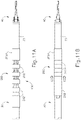
- FIGS. 11A and 11B show shaft assembly (30) of instrument (10) described above having a collapsible and expandable tube (200) added thereon.
- tube (200) may function to selectively provide rigidity to articulation section (130) and/or to prevent inadvertent deflection of end effector (40) relative to outer sheath (32).
- Tube (200) of the present example comprises a plurality of annular members (202) disposed about shaft assembly (30), including articulation section (130).
- annular members (202) are longitudinally translatable along a length of shaft assembly (30) relative to one another between an expanded configuration ( FIG. 11A ) and a collapsed configuration ( FIG. 11B ).
- annular members (202) when in the collapsed configuration, annular members (202) function to provide rigidity to articulation section (130) and/or to prevent inadvertent deflection of end effector (40) relative to outer sheath (32).
- a distal-most ring-shaped member (202A) of tube (200) is secured to an exterior surface of distal outer sheath (33) of shaft assembly (30) distally of articulation section (130).
- the remainder of annular members (202) of outer sheath (200) are slidably disposed about shaft assembly (30), including articulation section (130), such that annular members (202) are translatable along a length shaft assembly (30) relative to one another.
- annular members (202) when in the expanded configuration, annular members (202), although positioned about articulation section (130), are spaced apart from one another.
- annular members (202) may be translated distally toward distal-most ring-shaped member (202A) into the collapsed configuration.
- annular members (202) abut one another to form a substantially continuous and rigid tubular member.
- annular members (202) function to provide rigidity to articulation section (130) and/or to prevent inadvertent deflection of end effector (40) relative to outer sheath (32). If a user then desires to deflect end effector (40), annular members (202) may be moved back to the expanded configuration to permit articulation section (130) to flex.
- annular members (202) may be moved directly (e.g. by grasping one or more of annular members (202) directly, etc.) or by providing instrument (10) with additional actuation features.
- handle assembly (20) of instrument (10) may be provided with a slidable actuator that is operable to cause independent or concurrent translation of annular members (202).
- tube (200) may be provided with additional features that are configured to improve the structural integrity of tube (200) when in the collapsed configuration.
- annular members (202) may be provided with mating projections and recesses or slots that are configured to allow annular members (202) to further engage one another when in the collapsed configuration.
- annular members (202) may be provided with mating pins and pinholes that are configured to allow annular members (202) to further engage one another when in the collapsed configuration.
- annular members (202) may be tethered to each other by wires, cables, or other kinds of flexible members.
- such tethers may communicate the proximal motion from the proximal-most annular member (202) to the rest of the annular members (202), thereby pulling the rest of the proximal members from the positions shown in FIG. 11B to the positions shown in FIG. 11A .
- Such tethers may have a length selected to provide the spacing shown in FIG. 11A ; while also having the flexibility to allow annular members (202) to reach the positions shown in FIG. 11B .
- annular members (202) may be configured, actuated, and coupled with each other will be apparent to those of ordinary skill in the art in view of the teachings herein.
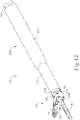
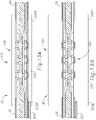
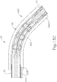
- FIGS. 12-13C show shaft assembly (30) of instrument (10) described above having an inflatable and deflatable balloon (220) secured thereto.
- balloon (220) may function to selectively provide rigidity to articulation section (130) and/or to prevent inadvertent deflection of end effector (40) relative to outer sheath (32).
- Balloon (220) of the present example comprises a tubular body (222) disposed about shaft assembly (30), including articulation section (130). Fluid is provided to tubular body (222) via a tube (224) which extends along a length of shaft assembly (30) adjacent an exterior surface of outer sheath (30).
- tube (224) functions to provide fluid to or to remove fluid from tubular body (222) so as to transition balloon (220) between a deflated state ( FIG. 13A and 13C ) and an inflated state ( FIG. 13B ).
- balloon (220) when in the inflated state, balloon (220) functions to provide rigidity to articulation section (130) and/or to prevent inadvertent deflection of end effector (40) relative to outer sheath (32) when balloon (220) is in an inflated state.
- Tubular body (222) is disposed about shaft assembly (30), including articulation section (130).
- tubular body (222) is formed of a flexible yet non-extensible material.
- a distal end (222A) of tubular body (222) is secured to an exterior surface of distal outer sheath (33) of shaft assembly (30) distally of articulation section (130).
- a proximal end (222B) of tubular body (222) is secured to an exterior surface of outer sheath (32) of shaft assembly (30) proximally of articulation section (130).
- tubular body (222) completely encompasses articulation section (130).
- tubular body (222) when in the deflated state, tubular body (222), although positioned about articulation section (130), remains flexible enough to allow articulation section (130) to flex to thereby deflect end effector (40) relative to outer sheath (32).
- tubular body (222) when in the inflated state, tubular body (222) becomes more rigid and functions to provide rigidity to articulation section (130) and/or to prevent inadvertent deflection of end effector (40) relative to outer sheath (32). If a user then desires to deflect end effector (40), tubular body (222) may be deflated to permit articulation section (130) to flex.
- the fluid communicated to tubular body (222) comprises saline, though it should be understood that any other suitable fluid may be used.
- any other suitable fluid may be used.
- fluid e.g., saline, etc.
- a fluid syringe may be coupled with a proximal end of tube (224) to thereby provide fluid to and to remove fluid from tubular body (222).
- the non-extensibility of tubular body may enable tubular body (222) to be inflated to pressures that make tubular body (222) substantially rigid, thereby effectively rigidizing articulation section (130).
- suitable fluid pressures and volumes that may be used for balloon (220) will be apparent to those of ordinary skill in the art in view of the teachings herein.
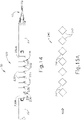
- FIGS. 14-18B show shaft assembly (30) of instrument (10) described above having an accordion-like rigidizing member (240) incorporated therein.
- rigidizing member (240) may function to selectively provide rigidity to articulation section (130) and/or to prevent inadvertent deflection of end effector (40) relative to outer sheath (32).
- rigidizing member (240) of the present example comprises a plurality of bellows (242) linked to one another along a length of rigidizing member (240).
- rigidizing member (240) is longitudinally translatable along a length of shaft assembly (30) so as to transition bellows (242) between a contracted configuration ( FIG. 15A ) and an expanded configuration ( FIG. 15B ).
- bellows (242) of rigidizing member (240) function to provide rigidity to articulation section (130) and/or to prevent inadvertent deflection of end effector (40) relative to outer sheath (32).
- rigidizing member (240) may be formed by a series of linkages that pivotably define bellows (242). Use of the term “bellows" should therefore be understood to not necessarily require a vessel that defines a variable capacity.
- Various suitable ways in which rigidizing member (240) may be configured will be apparent to those of ordinary skill in the art in view of the teachings herein.
- shaft assembly (30) of the present example comprises a plurality of couplers (230) pivotably linked to one another via a plurality of pins (232).
- Couplers (230) are disposed about shaft assembly (30), including articulation section (130).
- a distal-most coupler (230A) of couplers (230) is secured to an exterior surface of distal outer sheath (33) of shaft assembly (30) distally of articulation section (130).
- a proximal-most coupler (230B) of couplers (230) is secured to an exterior surface of outer sheath (32) of shaft assembly (30) proximally of articulation section (130).
- Each coupler (230) includes a pair of angled surfaces (234) which, when couplers (230) are linked to one another, forms a plurality of V-shaped pockets (236) in a side surface rigidizing member (240). Pockets (236) are configured to provide clearance between couplers (230) to allow couplers (230) to pivot relative to each other about pins (232) as articulation section (130) is articulated. Pockets (236) are also configured to receive bellows (242) as described in greater detail below.
- pockets (236) are shown on only one side of couplers (230) in this example, it should be understood that pockets (236) may be provided on both sides of couplers (230) if desired. Such a configuration may permit or facilitate articulation of articulation sections in two opposite directions relative to the longitudinal axis of outer sheath (32).
- bellows (242) of rigidizing member (240) are configured to extend through V-shaped pockets (236) and bear against angled surfaces (234) of couplers (230) to thereby provide rigidity to articulation section (130) and/or to prevent inadvertent deflection of end effector (40) relative to outer sheath (32).
- rigidizing member (240) is drawn proximally so as to transition bellows (242) to the expanded configuration.
- bellows (242) draws bellows (242) inwardly from V-shaped pockets (236) such that bellows (242) no longer bear against angled surfaces (234) of couplers (230) and such that articulation section (130) may flex to thereby deflect end effector (40) relative to outer sheath (32).
- rigidizing member (240) may be coupled with rotation knob (120) such that rotation of rotation knob (120) causes concurrent articulation of articulation section (130) and translation of rigidizing member (240).
- the proximal end of rigidizing member (240) may be coupled with rotation knob (120) via a slot (117) formed in a side of first hollow cylindrical portion (112) of housing (110).
- the distal end of rigidizing member (240) may be fixedly secured to distal outer sheath (33) or some other structure that is distal to articulation section (130).
- rigidizing member (240) is concurrently drawn proximally so as to transition bellows (242) from the configuration shown in FIG. 17A to the configuration shown in FIG. 17B .
- This causes bellows (242) to disengage angled surfaces (234), thus allowing articulation section (130) to flex to thereby deflect end effector (40) relative to outer sheath (32).
- rigidizing member (240) is concurrently driven distally so as to transition bellows (242) back from the configuration shown in FIG. 17B to the configuration shown in FIG. 17A .
- This causes bellows (242) to re-engage angled surfaces (234), thus providing rigidity to articulation section (130) and/or preventing inadvertent deflection of end effector (40) relative to outer sheath (32). It should therefore be understood that articulation section (130) may be automatically rigidized upon reaching a straight configuration.
- FIGS. 19-21B show a rigidizing member (260) that may be used in lieu of rigidizing member (240) discussed above.
- rigidizing member (260) of the present example comprises an elongate shaft (262), having a rectangular cross-section, and a plurality of pegs (264) extending transversely from a side surface of shaft (262).
- rigidizing member (260) is laterally translatable within an interior space of shaft assembly (30) between a first position ( FIG. 21A ) and a second position ( FIG. 21B ).
- pegs (264) of rigidizing member (260) function to provide rigidity to articulation section (130) and/or to prevent inadvertent deflection of end effector (40) relative to outer sheath (32).
- rigidizing member (260) is configured to be positioned within an interior space of shaft assembly (30), including articulation section (130).
- pegs (264) are configured to extend through V-shaped pockets (236) and bear against (or at least contact) angled surfaces (234) of couplers (230) to thereby provide rigidity to articulation section (130) and/or to prevent inadvertent deflection of end effector (40) relative to outer sheath (32).
- pegs (264) are configured to extend through V-shaped pockets (236) and bear against (or at least contact) angled surfaces (234) of couplers (230) to thereby provide rigidity to articulation section (130) and/or to prevent inadvertent deflection of end effector (40) relative to outer sheath (32).
- rigidizing member (260) is translated laterally inwardly into the second position to thereby draw pegs (264) inwardly from V-shaped pockets (236) such that pegs (264) no longer bear against (or otherwise contact) angled surfaces (234) of couplers (230). With pegs (264) moved out of V-shaped pockets (236), articulation section (130) is free to flex to thereby deflect end effector (40) relative to outer sheath (32).
- articulation section (130) is free to flex to thereby deflect end effector (40) relative to outer sheath (32).
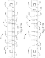
- FIGS. 22-23C show a variable-thickness rigidizing member (280) that may be incorporated into articulation section (130) of shaft assembly (30) of instrument (10).
- rigidizing member (280) may function to selectively provide rigidity to articulation section (130) and/or to prevent inadvertent deflection of end effector (40) relative to outer sheath (32).
- rigidizing member (280) of the present example comprises a plurality of flanges (282) linked to one another by a plurality of flexible rods (284), which are positioned between consecutive flanges (282). It should be understood that rods (284) may be substituted with wires, cables, or any other suitable kind of flexible member.
- rigidizing member (280) is longitudinally translatable along a length of shaft assembly (30) so as to transition flanges (282) between a first position ( FIG. 23A ) and a second position ( FIGS. 23B and 23C ). Also as will be described in more detail below, when in the first position, flanges (282) of rigidizing member (280) function to provide rigidity to articulation section (130) and/or to prevent inadvertent deflection of end effector (40) relative to outer sheath (32).
- a modified version of shaft assembly (30) comprises a plurality of couplers (290) that are pivotably linked to one another via a plurality of pins (292). Couplers (290) are disposed about shaft assembly (30), including articulation section (130).
- a distal-most coupler (290A) of couplers (290) is secured to an exterior surface of distal outer sheath (33) of shaft assembly (30) distally of articulation section (130).
- a proximal-most coupler (290B) of couplers (290) is secured to an exterior surface of outer sheath (32) of shaft assembly (30) proximally of articulation section (130).
- couplers (290) when linked to one another via pins (292), couplers (290) completely encompass articulation section (130).
- couplers (290) are pivotably linked to one another via a plurality of pins (292) such that couplers (290) pivot about a plurality of axes defined by pins (292).
- Pins (292), which pivotably link couplers (290) to one another, are aligned such that articulation section (130) may flex along a plane (P1) oriented perpendicular to the axes of rotation of pins (292).
- rigidizing member (280) is configured to be positioned within an interior space of shaft assembly (30), including articulation section (130), inside the assembly formed by couplers (290).
- Rigidizing member (280) is oriented such that flanges (282) are substantially parallel to plane (P1) and perpendicular to the axes of rotation of pins (292).
- flanges (282) of rigidizing member (280) are positioned such that each flange (282) extends between a space defined by consecutive couplers (290) and such that pins (292) are positioned above and below an intermediate portion of flanges (282).
- flanges (282) are positioned at the joints of couplers (290), flanges (282) prevent couplers (290) from flexing at those joints. This further prevents flexing at articulation section.
- rigidizing member (280) is in the position shown in FIG. 23A , the assembly formed by rigidizing member (280) and couplers (290) prevents bending of articulation section (130) and effectively rigidizes articulation section (130).
- rigidizing member (280) is translated proximally so as to move flanges (282) away from the joints of couplers (290) and to position flexible rods (284) at the joints of couplers (290).
- This positioning enables couplers (290) to pivot at the joints.
- couplers (290) being enabled to pivot
- flexible rods (284) being enabled to flex
- articulation section (130) is thereby enabled to articulate as shown in FIG. 23C .
- rigidizing member (280) may be actuated between the position shown in FIG. 23A and the positions shown in FIGS. 23B-23C will be apparent to those of ordinary skill in the art in view of the teachings herein.
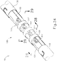
- FIGS. 24-29C show shaft assembly (30) of instrument (10) described above having a variable-thickness rigidizing member (300) incorporated therein.
- rigidizing member (300) may function to selectively provide rigidity to articulation section (130) and/or to prevent inadvertent deflection of end effector (40) relative to outer sheath (32).
- rigidizing member (300) of the present example comprises a plurality of flanges (302) linked to one another by a plurality of flexible rods (304) that are positioned between consecutive flanges (302). It should be understood that rods (304) may be substituted with wires, cables, or any other suitable kind of flexible member. As shown in FIG.
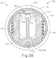
- flanges (302) of the present example have a rectangular cross-section.
- flanges (302) have a circular segment cross-section as shown in FIG. 27 .
- flanges (302) may have any other suitable cross-section as will be appreciated by one of ordinary skill in the art in view of the teachings herein.
- rigidizing member (300) is longitudinally translatable along a length of shaft assembly (30) so as to transition flanges (302) between a first position ( FIG. 29A ) and a second position ( FIGS. 29B and 29C ).
- flanges (302) of rigidizing member (300) function to provide rigidity to articulation section (130) and/or to prevent inadvertent deflection of end effector (40) relative to outer sheath (32).
- shaft assembly (30) of the present example defines a channel (310) in a top portion of ribbed body portions (132, 134) of articulation section (130).
- Channel (310) is configured to slidably receive rigidizing member (300) such that rigidizing member (300) is longitudinally translatable within channel (310) along a length of shaft assembly (30).
- rigidizing member (300) is configured to be positioned within an interior space of shaft assembly (30), including articulation section (130).
- Rigidizing member (300) is oriented such that flanges (302) are substantially parallel to a plane (P2) along which articulation member (130) is configured to flex.
- P2 a plane along which articulation member (130) is configured to flex.
- flanges (302) of rigidizing member (300) are positioned such that each flange (302) extends between the spaces between consecutive retention collars (133).
- flanges (302) Because of the orientation and position of flanges (302) in this state, and because of the width of flanges (302), flanges (302) block relative movement of retention collars (133) along plane (P2). Rigidizing member (300) thus prevents bending of articulation section (130) and effectively rigidizes articulation section (130).
- rigidizing member (300) is translated proximally so as to position flanges (302) away from the spaces between consecutive retention collars (133) and to position flexible rods (304) between the spaces between consecutive retention collars (133).
- This positioning enables retention collars (133) to move relative to each other along plane (P2).
- articulation section (130) is thereby enabled to articulate as shown in FIG 29C .
- rigidizing member (300) may be actuated between the position shown in FIG. 29A and the positions shown in FIGS. 29B-29C will be apparent to those of ordinary skill in the art in view of the teachings herein.
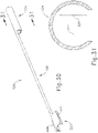
- FIGS. 30-32C show an exemplary rigidizing sleeve member (320).
- rigidizing sleeve member (320) may function to selectively provide rigidity to articulation section (130) and/or to prevent inadvertent deflection of end effector (40) relative to outer sheath (32).
- rigidizing member (320) of the present example comprises a proximal semi-circular-cylindrical portion (322) and a distal semi-circular-cylindrical portion (324). Portions (322, 324) are coupled together via a flexible rod (326).
- Rod (326) provides lateral flexibility yet has sufficient column strength to provide effective actuation of rigidizing sleeve member (320) as described below. It should be understood that rod (326) may be substituted with a band or any other suitable kind of flexible member. Cylindrical portions (322, 324) are sized to receive and selectively couple about shaft assembly (30) in a snap-fit manner. As will be described in more detail, however, sleeve member (320) remains able to translate longitudinally along a length of shaft assembly (30) so as to transition distal cylindrical portion (324) between a first position ( FIG. 32A ) and a second position ( FIGS. 32B and 32C ).
- distal cylindrical portion (324) of sleeve member (320) functions to provide rigidity to articulation section (130) and/or to prevent inadvertent deflection of end effector (40) relative to outer sheath (32).
- proximal cylindrical portion (322) comprises a pair of flanges (328) extending from opposing sides of an exterior surface of proximal cylindrical portion (322).
- a user may engage flanges (328) to assist the user in positioning proximal cylindrical portion (322) about and removing proximal cylindrical portion (322) from shaft assembly (30).
- any other suitable features may be used to facilitate manipulation of proximal cylindrical portion (322).
- distal cylindrical portion (324) comprises a plurality of rectangular projections (327) extending inwardly from an interior surface of distal cylindrical portion (324).
- distal cylindrical portion (324) is configured to be positioned about shaft assembly (30), in particular, about articulation section (130). As shown in FIG. 32A , with distal cylindrical portion (324) in the first position, projections (327) of distal cylindrical portion (324) are positioned such that each projection (327) is positioned within a corresponding space defined between consecutive retention collars (133) such that projections (327) abut consecutive retention collars (133).
- projections (327) abut consecutive retention collars (133) when sleeve member (320) is in the first position, projections (327) function to provide rigidity to articulation section (130) and/or to prevent inadvertent deflection of end effector (40) relative to outer sheath (32) by preventing movement of retention collars (133) relative to each other.
- rigidizing sleeve member (320) is translated proximally so as to draw projections (327) from the spaces defined by consecutive retention collars (133) and so as to position projections (327) adjacent an exterior surface of retention collars (133). With sleeve member (320) in this position, the space between consecutive retention collars (133) allows articulation section (130) to flex to thereby deflect end effector (40) relative to outer sheath (32) as shown in FIG. 32C .
- Distal cylindrical portion (324) is formed of a resilient material that enables projections (327) to deflect outwardly from the position shown in FIG. 32A to the position shown in FIGS. 32B and 32C .
- the resilient properties of distal cylindrical portion (324) also cause projections (327) to snap back into the spaces defined between consecutive retention collars (133) when sleeve member (320) is advanced distally back to the position shown in FIG. 32A .
- sleeve member (320) may be returned to the position shown in FIG. 32A after articulation section (130) has been returned to a straight, non-articulated configuration.
- sleeve member (320) is translated between the distal position ( FIG.
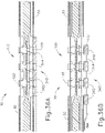
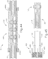
- FIGS. 33-37B show another exemplary rigidizing member (340).
- rigidizing member (340) may function to selectively provide rigidity to articulation section (130) and/or to prevent inadvertent deflection of end effector (40) relative to outer sheath (32).
- rigidizing member (340) of the present example comprises a plurality of C-channel members (342) linked to one another by a plurality of flexible rods (344), which are positioned between consecutive C-channel members (342). It should be understood that rods (344) may be substituted with wires, cables, or any other suitable kind of flexible member.
- rigidizing member (340) is configured to translate longitudinally along a length of shaft assembly (30) so as to transition C-channel members (342) between a first position ( FIG. 36A ) and a second position ( FIGS. 36B and 36C ). Also as will be described in more detail below, when rigidizing member (340) is in the first position, C-channel members (342) of rigidizing member (340) function to provide rigidity to articulation section (130) and/or to prevent inadvertent deflection of end effector (40) relative to outer sheath (32).
- C-channel members (342) are configured to be positioned about shaft assembly (30), in particular, about articulation section (130). As shown in FIG. 36A , with rigidizing member (340) in the first position, C-channel members (342) are positioned such that each C-channel member (342) is positioned within a corresponding space defined between consecutive retention collars (133) such that C-channel members (342) abut consecutive retention collars (133).
- C-channel members (342) abut consecutive retention collars (133) when rigidizing member (340) is in the first position, C-channel members (342) function to provide rigidity to articulation section (130) and/or to prevent inadvertent deflection of end effector (40) relative to outer sheath (32) by preventing movement of retention collars (133) relative to each other.
- rigidizing member (340) is translated proximally so as to draw C-channel members (342) from the spaces defined between consecutive retention collars (133) and so as to position C-channel members (342) adjacent an exterior surface of retention collars (133). With rigidizing member (340) in this position, the space between consecutive retention collars (133) allows articulation section (130) to flex to thereby deflect end effector (40) relative to outer sheath (32) as shown in FIG. 36C .
- Rigidizng member (340) is formed of a resilient material that enables C-channel members (342) to deform and deflect outwardly from the position shown in FIG. 36A to the position shown in FIGS. 36B and 36C .
- the resilient properties of C-channel members (342) also cause C-channel members (342) to snap back into the spaces defined between consecutive retention collars (133) when rigidizing member (340) is advanced distally back to the position shown in FIG. 36A .
- rigidizing member (340) may be returned to the position shown in FIG. 36A after articulation section (130) has been returned to a straight, non-articulated configuration.
- articulation section (130) has been returned to a straight, non-articulated configuration.
- a pair of rigidizing members (340) may be positioned on opposite lateral sides of articulation section (130) to provide rigidity to articulation section (130) and/or to prevent inadvertent deflection of end effector (40) relative to outer sheath (32) in multiple directions.
- FIGS. 38-39B show an exemplary rigidizing clip member (360).
- rigidizing clip member (360) may function to selectively provide rigidity to articulation section (130) and/or to prevent inadvertent deflection of end effector (40) relative to outer sheath (32).
- rigidizing clip member (360) of the present example comprises a semi-circular-cylindrical body (362).
- a plurality of slots (364) formed in opposing side surfaces of cylindrical body (362) separate a plurality of tabs (366).
- rigidizing clip member (360) is configured to be positioned about shaft assembly (30), in particular, about articulation section (130).
- tabs (366) function to provide rigidity to articulation section (130) and/or to prevent inadvertent deflection of end effector (40) relative to outer sheath (32) by preventing movement of retention collars (133) toward one another.
- clip member (360) may be formed of a resilient material such that clip member (360) may be removably secured to articulation section (130) through a snap fit. Alternatively, clip member (360) may be removably secured to articulation section (130) in any other suitable fashion.
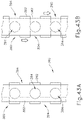
- FIGS. 40A-43B show a modified version of shaft assembly (30) of instrument (10) described above having a pair of overlapping articulation bands (380, 390).
- articulation bands (380, 390) may function to provide rigidity to articulation section (130) and/or to prevent inadvertent deflection of end effector (40) relative to outer sheath (32).
- articulation band (380) comprises an elongate strip (382) having a plurality of circular openings (384) formed therein to provide "weak spots" along the length of strip (382). Circular openings (384) are spaced apart from one another, and provide flexibility to articulation band (380) at circular openings (384).
- articulation band (390) comprises an elongate strip (392) having a plurality of opposing rectangular recesses (394) formed therein to provide "weak spots" along the length of strip (392). Rectangular recesses (394) are spaced apart from one another, and provide flexibility to articulation band (390) at rectangular recesses (394). The spacing of recesses (394) corresponds to the spacing of openings (384).
- articulation bands (380, 390) are positioned within an interior space of shaft assembly (30), including articulation section (130).
- One set of articulation bands (380, 390) is positioned on one side of waveguide (180); while another set of articulation bands (380, 390) is positioned on the other side of waveguide (180).
- Articulation bands (380, 390) are longitudinally translatable relative to one another between a first configuration ( FIG. 43A ) and a second configuration ( FIG. 43B ). As shown in FIG.
- articulation bands (380, 390) overlap one another in an arrangement such that circular openings (384) of articulation band (380) are offset from rectangular recesses (394) of articulation band (390).
- circular openings (384) of articulation band (380) are offset from rectangular recesses (394) of articulation band (390).
- the remaining “strong spots” of articulation bands (380, 390) accommodate for the "weak spots” and prevent articulation bands (380, 390) from flexing.
- Articulation bands (380, 390) thus cooperate to provide rigidity to articulation section (130) and/or prevent inadvertent deflection of end effector (40) relative to outer sheath (32) when articulation bands (380, 390) are arranged as shown in FIG. 43A .
- articulation bands (380, 390) are positioned in this arrangement when articulation section (130) is in a straight, non-articulated configuration as shown in FIG. 40A .
- articulation bands (380, 390) overlap one another in an arrangement such that circular openings (384) of articulation band (380) align with rectangular recesses (394) of articulation band (390).
- articulation bands (380, 390) may flex to thereby allow articulation section (130) to flex to thereby deflect end effector (40) relative to outer sheath (32).
- articulation bands (380, 390) cooperate to provide flexibility to articulation section (130) when articulation bands (380, 390) are arranged as shown in FIG. 43B .
- Articulation control assembly (100) may be readily modified to provide coordinated movement of articulation bands (380, 390).
- articulation control assembly (100) is configured such that knob (120) is rotatable through two ranges of motion from a neutral position where articulation section (130) is in a straight, non-articulated configuration as shown in FIG. 40A .
- knob (120) With knob (120) in the neutral position, articulation bands (380, 390) are in the arrangement shown in FIG. 43A , such that articulation bands (380, 390) rigidize articulation section (130), with articulation section (130) being in the straight, non-articulated configuration.
- articulation control assembly (100) drives a first articulation band (380, 390) in each pair of articulation bands (380, 390) relative to a second articulation band (380, 390) in that pair.
- the second articulation band (380, 390) remains stationary during this first range of motion of knob (120).
- each pair of articulation bands (380) is transitioned to the configuration shown in FIG. 43B , such that articulation bands (380, 390) are arranged to provide flexibility.
- articulation control assembly (100) drives a both articulation bands (380, 390) of one pair together in a first longitudinal direction, while simultaneously driving both articulation bands (380, 390) of the other pair together in a second longitudinal direction.
- the pairs of articulation bands (380, 390) thus cooperate to drive articulation as knob (120) is rotated through the second range of motion.
- knob (120) When the operator wishes to subsequently transition articulation section (130) back to a straight, non-articulated state, the operator may simply reverse rotation of knob (120). During this reversal, the pairs of articulation bands (380, 390) will again cooperate to drive articulation section (130) back to the straight, non-articulated state. Once articulation section (130) reaches the straight, non-articulated state, knob (120) will transition from the second range of motion back to the first range of motion as knob (120) is further rotated.
- articulation control assembly (100) again drives a first articulation band (380, 390) in each pair of articulation bands (380, 390) relative to a second articulation band (380, 390) in that pair.
- the second articulation band (380, 390) remains stationary during this first range of motion of knob (120).
- articulation bands (380, 390) are again returned to the arrangement shown in FIG. 43A , such that articulation bands (380, 390) again rigidize articulation section (130).
- knob (120) is used in the present example, it should be understood that any other suitable kind of actuator may be used, including but not limited to a slider, a lever, a dial, etc.
- knob (120) is operable to both selectively rigidize articulation section (130) (as knob (120) is rotated through the first range of motion) and to drive articulation of articulation section (130) (as knob (120) is rotated through the second range of motion).
- two separate actuators are used - one actuator to selectively rigidize articulation section (130) and another actuator to drive articulation of articulation section (130).
- any other example described herein for selectively rigidizing articulation section (130) may also be coupled with a modified version of articulation control assembly (100) as described above.
- any other example described herein for selectively rigidizing articulation section (130) may be coupled with a knob (120) that rotates through two ranges of motion - a first range of motion to selectively rigidize articulation section (130) and a second range of motion to drive articulation of articulation section (130).
- any other kind of actuator may be used, including but not limited to a slider, a lever, a dial, etc.
- Such alternative actuators may also be moved through two different ranges of motion to selectively rigidize articulation section (130) (during a first range of motion of the actuator) and to drive articulation of articulation section (during a second range of motion of the actuator).
- any other example described herein for selectively rigidizing articulation section (130) may also be coupled with two separate actuators --- one actuator to selectively rigidize articulation section (130) and another actuator to drive articulation of articulation section (130).
- Various suitable ways in which these exemplary alternatives may be incorporated into the various examples described herein will be apparent to those of ordinary skill in the art in view of the teachings herein.
- FIG. 44 shows a modified version of shaft assembly (30) of instrument (10) having a tubular member (400) that is configured to selectively rigidize.
- tubular member (400) may function to selectively provide rigidity to articulation section (130) and/or to prevent inadvertent deflection of end effector (40) relative to outer sheath (32).
- Tubular member (400) comprises hollow-cylindrical body (402) filled with magnetorheological fluid (MR fluid) (404). Cylindrical body (402) is positioned about shaft assembly (30) and encompasses articulation section (130). Cylindrical body (402) is capped at a distal end and a proximal end by a pair of magnets (406).
- MR fluid magnetorheological fluid
- magnets (406) comprise electromagnets, such that magnets (406) may be selectively activated (and thereby be selectively magnetized) by application of an electric current to magnets (406).
- a distal magnet (406A) of magnets (406) is secured to an exterior surface of distal outer sheath (33) of shaft assembly (30) distally of articulation section (130).
- a proximal magnet (406B) of magnets (406) is secured to an exterior surface of outer sheath (32) of shaft assembly (30) proximally of articulation section (130).
- Magnets (406) are in direct contact with MR fluid (404) such that magnets (406) may function to selectively magnetize MR fluid (404) based on selective activation of magnets (406).
- cylindrical body (402) of tubular member (400) Prior to magnetizing MR fluid (404), cylindrical body (402) of tubular member (400) is operable to flex to thereby allow articulation section (130) to flex to thereby deflect end effector (40) relative to outer sheath (32).
- MR fluid (404) becomes substantially rigid within cylindrical body (402) to thereby rigidize tubular member (400).
- tubular member (400) may function to provide rigidity to articulation section (130) and/or to prevent inadvertent deflection of end effector (40) relative to outer sheath (32).
- one or more wires, conductive traces, and/or other electrically conductive conduits may extend along the length of shaft assembly (30) to enable electrical power to be selectively delivered to magnets (406)
- articulation control assembly (100) is modified such that knob (120) causes closure of an electrical switch when knob (120) is rotated to a neutral position that is associated with articulation section (130) being in a straight, non-articulated configuration.
- This switch may be in communication with magnets (406) and a source of electrical power such that magnets (406) are activated when knob (120) is in the neutral position.
- Articulation section (130) will thus be rigidized when knob (120) is in the neutral position, with articulation section (130) in the straight, non-articulated configuration.
- the switch will be transitioned to an open state, thereby deactivating magnets (406), thereby de-rigidizing articulation section (130) and allowing articulation section (130) to be articulated.
- the switch will again be closed, thereby re-activating magnets (406), thereby rigidizing articulation section (130) again as articulation section (130) reaches the straight, non-articulated configuration.
- magnets (406) may be selectively activated will be apparent to those of ordinary skill in the art in view of the teachings herein.
- FIG. 45 shows a modified version of shaft assembly (30) of instrument (10) described above having a valve assembly (420).
- valve assembly (420) is configured to selectively rigidize so as to provide rigidity to articulation section (130) and/or to prevent inadvertent deflection of end effector (40) relative to outer sheath (32).
- Valve assembly (420) comprises a pair of plungers (422, 424) that are slidably disposed within a pair of cylinders (426, 428).
- Plungers (422, 424) are coupled with articulation bands (140, 142) of shaft assembly (130) such that translation of articulation bands (140, 142) caused by articulation of articulation section (130) causes concurrent translation of plungers (422, 424) within cylinders (426, 428).
- Cylinders (426, 428) are filled with MR fluid (430, 432).
- One or more electromagnets are in direct contact with MR fluid (430, 432) such that the electromagnets may selectively magnetize MR fluid (430, 432) when the electromagnets are activated.
- plungers (422, 424) Prior to magnetizing MR fluid (430, 432), plungers (422, 424) are operable to translate within cylinders (426, 428) to thereby allow articulation section (130) to flex to thereby deflect end effector (40) relative to outer sheath (32).
- MR fluid (430, 432) Once MR fluid (430, 432) is magnetized, however, MR fluid (430, 432) becomes substantially rigid within cylinders (426, 428) to thereby prevent movement of plungers (422, 424) to thereby prevent movement of articulation bands (140, 142) so as to provide rigidity to articulation section (130) and/or to prevent inadvertent deflection of end effector (40) relative to outer sheath (32).
- Various suitable ways in which MR fluid (430, 432) may be selectively magnetized will be apparent to those of ordinary skill in the art in view of the teachings herein.
- FIG. 46 shows a modified version shaft assembly (30) of instrument (10) described above having a pair of exemplary alternative articulation bands (440, 442).
- articulation bands (440, 442) may function to provide rigidity to articulation section (130) and/or to prevent inadvertent deflection of end effector (40) relative to outer sheath (32).
- Each articulation band (440, 442) comprises a plurality of teeth (444, 446) projecting outwardly from opposing side surfaces of articulation bands (440, 442).
- An interior surface of outer sheath (32) comprises two sets of teeth (450, 452) projecting inwardly from opposing sides of an interior surface of outer sheath (32).
- Teeth (444, 446) of articulation bands (440, 442) are configured to engage teeth (450, 452) of outer sheath (32) to thereby limit longitudinal translation of articulation bands (440, 442). Limiting the longitudinal translation of articulation bands (440, 442) subsequently limits articulation of articulation section (130).
- teeth (444, 446, 450, 452) may function to merely limit actuation of articulation section (130) or to substantially limit actuation of articulation section (130) by requiring a lesser or greater force to articulate articulation section (130).
- articulation bands (440, 442) are configured to transition laterally between an inward configuration and an outward configuration.
- teeth (444, 446) are disengaged from teeth (450, 452), allowing articulation bands (440, 442) to translate freely (e.g., to freely drive articulation of articulation section (130)).
- teeth (444, 446) are engaged with teeth (450, 452), with enough force to prevent articulation bands (440, 442) from translating.
- articulation bands (440, 442) being rigidly prevented from translating, articulation section (130) is effectively rigidized.
- articulation bands (440, 442) may be selectively transitioned between the inward configuration and the outward configuration will be apparent to those of ordinary skill in the art in view of the teachings herein.
- articulation bands (440, 442) are resiliently biased outwardly such that teeth (444, 446) are biased into engagement with teeth (450, 452). Teeth (444, 446) remain engaged with teeth (450, 452), yet teeth (444, 446) are permitted to slide along teeth (450, 452) in a ratcheting fashion as articulation bands (440, 442) are opposingly translated to drive articulation of articulation section (130).
- articulation bands (440, 442) are held longitudinally stationary, engagement between teeth (444, 446) and teeth (450, 452) will prevent articulation section (130) from having any "play", such that teeth (444, 446) and teeth (450, 452) cooperate to effectively rigidize articulation section (130).
- teeth (444, 446) and teeth (450, 452) are positioned proximate to articulation section (130) in this example, thereby minimizing any tolerance stacking that might otherwise frustrate the rigidization functionality in cases where teeth (444, 446) and teeth (450, 452) would be positioned further remotely from articulation section (130).
- FIGS. 47A and 47B show a modified version of shaft assembly (30) of instrument (10) described above having a pair of exemplary alternative articulation bands (460, 462).
- Articulation bands (460, 462) are coupled with a power source (464) that is operable to provide an electrical current to articulation bands (460, 462).
- Articulation bands (460, 462) of the present example comprise a "smart material” (e.g. "muscle wire” shape memory alloy, electroactive polymer, etc.). In the absence of a current being applied to it, such a "smart material” may be stretched by a small force.
- a "smart material” may be stretched by a small force.
- articulation bands (460, 462) may easily flex to thereby allow articulation section (130) to flex so as to deflect end effector (40) relative to outer sheath (32).
- a current is applied to such a "smart material," the material becomes substantially harder and returns to its original length (e.g., a length that is shorter than the length when the current is removed).
- articulation bands (460, 462) once power source (464) provides an electrical current to articulation bands (460, 462), articulation bands (460, 462) become substantially rigid and return to their original (e.g., shorter) lengths so as to provide rigidity to articulation section (130) and/or to prevent inadvertent deflection of end effector (40) relative to outer sheath (32).
- power source (464) provides an electrical current to articulation bands (460, 462)
- articulation bands (460, 462) become substantially rigid and return to their original (e.g., shorter) lengths so as to provide rigidity to articulation section (130) and/or to prevent inadvertent deflection of end effector (40) relative to outer sheath (32).
- power source (464) provides an electrical current to articulation bands (460, 462)
- articulation bands (460, 462) become substantially rigid and return to their original (e.g., shorter) lengths so as to provide rigidity to articulation section (130
- any of the versions of instruments described herein may include various other features in addition to or in lieu of those described above.
- any of the instruments described herein may also include one or more of the various features disclosed in any of the various references that are disclosed herein.
- teachings herein may be readily applied to any of the instruments described in any of the other references cited herein, such that the teachings herein may be readily combined with the teachings of any of the references cited herein in numerous ways.
- teachings herein may be readily applied to electrosurgical instruments, stapling instruments, and other kinds of surgical instruments.
- Other types of instruments into which the teachings herein may be incorporated will be apparent to those of ordinary skill in the art.
- Versions of the devices described above may have application in conventional medical treatments and procedures conducted by a medical professional, as well as application in robotic-assisted medical treatments and procedures.
- various teachings herein may be readily incorporated into a robotic surgical system such as the DAVINCI TM system by Intuitive Surgical, Inc., of Sunnyvale, California.
- DAVINCI TM system by Intuitive Surgical, Inc., of Sunnyvale, California.
- teachings herein may be readily combined with various teachings of U.S. Pat. No. 6,783,524, entitled "Robotic Surgical Tool with Ultrasound Cauterizing and Cutting Instrument," published August 31, 2004 .
- Versions described above may be designed to be disposed of after a single use, or they can be designed to be used multiple times. Versions may, in either or both cases, be reconditioned for reuse after at least one use. Reconditioning may include any combination of the steps of disassembly of the device, followed by cleaning or replacement of particular pieces, and subsequent reassembly. In particular, some versions of the device may be disassembled, and any number of the particular pieces or parts of the device may be selectively replaced or removed in any combination. Upon cleaning and/or replacement of particular parts, some versions of the device may be reassembled for subsequent use either at a reconditioning facility, or by a user immediately prior to a procedure.
- reconditioning of a device may utilize a variety of techniques for disassembly, cleaning/replacement, and reassembly. Use of such techniques, and the resulting reconditioned device, are all within the scope of the present disclosure.
- versions described herein may be sterilized before and/or after a procedure.
- the device is placed in a closed and sealed container, such as a plastic or TYVEK bag.
- the container and device may then be placed in a field of radiation that can penetrate the container, such as gamma radiation, x-rays, or high-energy electrons.
- the radiation may kill bacteria on the device and in the container.
- the sterilized device may then be stored in the sterile container for later use.
- a device may also be sterilized using any other technique known in the art, including but not limited to beta or gamma radiation, ethylene oxide, or steam.
Landscapes
- Health & Medical Sciences (AREA)
- Life Sciences & Earth Sciences (AREA)
- Surgery (AREA)
- Engineering & Computer Science (AREA)
- General Health & Medical Sciences (AREA)
- Veterinary Medicine (AREA)
- Nuclear Medicine, Radiotherapy & Molecular Imaging (AREA)
- Biomedical Technology (AREA)
- Public Health (AREA)
- Animal Behavior & Ethology (AREA)
- Molecular Biology (AREA)
- Medical Informatics (AREA)
- Heart & Thoracic Surgery (AREA)
- Dentistry (AREA)
- Mechanical Engineering (AREA)
- Ophthalmology & Optometry (AREA)
- Radiology & Medical Imaging (AREA)
- Surgical Instruments (AREA)
- Ultra Sonic Daignosis Equipment (AREA)
Claims (10)
- Instrument chirurgical à ultrasons (10) destiné à être utilisé sur un tissu, l'instrument chirurgical à ultrasons (10) comprenant :(a) un ensemble corps (20),(b) un ensemble tige (30), l'ensemble tige (30) s'étendant de manière distale depuis l'ensemble corps (20), l'ensemble tige (30) définissant un axe longitudinal ;(c) un effecteur terminal (40) comprenant une lame ultrasonore (160), l'effecteur terminal (40) étant situé à une extrémité distale de l'ensemble tige (30),(d) une section d'articulation (130), la section d'articulation (130) étant couplée à l'ensemble tige (30) et comprenant un guide d'ondes acoustiques (180) pour fournir une oscillation de la lame ultrasonore (160) à une fréquence ultrasonore de résonance, la section d'articulation (130) pouvant fonctionner pour fléchir afin de dévier ainsi l'effecteur d'extrémité (40) de l'axe longitudinal ; et(e) un élément de rigidification (200, 240, 280, 300, 320, 340) positionné à l'intérieur de la section d'articulation (130), l'élément de rigidification ayant une extrémité proximale et une extrémité distale définissant une longueur de l'élément de rigidification, la longueur de l'élément de rigidification (200, 240, 280, 300, 320, 340) étant utilisable pour se translater longitudinalement le long d'une longueur de la section d'articulation (130) pour ainsi rigidifier sélectivement la section d'articulation (130).
- Instrument chirurgical à ultrasons (10) selon la revendication 1, l'élément de rigidification comprenant un tube repliable et extensible (200) disposé de manière coulissante autour d'une partie de l'ensemble tige (30) et de la section d'articulation (130).
- Instrument chirurgical à ultrasons (10) selon la revendication 1, l'ensemble tige (30) comprenant une pluralité de coupleurs (133) reliés de manière pivotante les uns aux autres, l'élément de rigidification étant configuré pour mettre en prise de manière sélective la pluralité de coupleurs pour ainsi rigidifier la section d'articulation ; et éventuellement l'une des options suivantes étant remplie :a) l'élément de rigidification comprend un élément de rigidification en accordéon extensible et contractable (240) configuré pour venir en prise sélectivement avec la pluralité de coupleurs ; etb) l'élément de rigidification comprend une pluralité de chevilles configurées pour venir en prise sélectivement avec la pluralité de coupleurs.
- Instrument chirurgical à ultrasons (10) selon la revendication 1, l'ensemble tige (30) comprenant une pluralité de coupleurs (133) reliés de manière pivotante les uns aux autres, l'élément de rigidification étant configuré pour venir en prise sélectivement avec la pluralité de coupleurs pour ainsi rigidifier la section d'articulation et l'élément de rigidification (280) comprenant une pluralité de brides (282) reliées les unes aux autres par au moins un élément flexible (284), et éventuellement les brides (282) de la pluralité de brides comprenant un profil de section transversale rectangulaire.
- Instrument chirurgical à ultrasons (10) selon la revendication 1, l'élément de rigidification comprenant un élément de manchon de rigidification (320) disposé de manière coulissante autour d'une partie de l'ensemble tige (30) et de la section d'articulation (130), et éventuellement l'élément de manchon de rigidification (320) comprenant une pluralité de saillies (327), la pluralité de saillies (327) étant configurée pour venir en prise de manière sélective avec au moins une partie de la section d'articulation (130) pour ainsi rigidifier la section d'articulation (130).
- Instrument chirurgical à ultrasons (10) selon la revendication 1, l'ensemble tige (30) comprenant une pluralité de coupleurs (133) reliés de manière pivotante les uns aux autres, l'élément de rigidification (340) étant configuré pour venir en prise sélectivement avec la pluralité de coupleurs pour ainsi rigidifier la section d'articulation, et l'élément de rigidification (340) comprenant une pluralité d'éléments de canal en C (342) reliés les uns aux autres par au moins un élément flexible (344), et éventuellement la pluralité d'éléments de canal en C (342) étant configurés pour venir en prise sélectivement avec au moins une partie de la section d'articulation (130) pour ainsi rigidifier la section d'articulation (130).
- Instrument chirurgical à ultrasons (10) selon la revendication 1, l'élément de rigidification comprenant au moins une paire de bandes d'articulation se chevauchant (380, 390), chaque bande d'articulation (380, 390) de la pluralité de bandes structurelles comprenant une pluralité de points faibles, les bandes d'articulation se chevauchant (380, 390) étant mobiles les unes par rapport aux autres pour aligner ou décaler sélectivement les points faibles afin de fournir ainsi une flexibilité ou une rigidité à l'élément de rigidification.
- Instrument chirurgical à ultrasons (10) selon la revendication 1, l'élément de rigidification (200, 240, 280, 300, 320, 340) étant utilisable pour venir en prise sélectivement avec au moins une partie de la section d'articulation (130) pour ainsi rigidifier sélectivement la section d'articulation.
- Instrument chirurgical à ultrasons (10) selon la revendication 8, la section d'articulation comprenant une pluralité de colliers de retenue (133), l'élément de rigidification (200, 240, 280, 300, 320, 340) étant utilisable pour venir en prise sélectivement avec les colliers de retenue (133) de la section d'articulation pour ainsi rigidifier la section d'articulation.
- Instrument chirurgical à ultrasons (10) selon la revendication 1, l'élément de rigidification (200, 240, 280, 300, 320, 340) étant mobile longitudinalement le long d'une longueur de l'ensemble tige (30) entre une première position et une seconde position, la section d'articulation (130) étant utilisable pour fléchir pour ainsi dévier l'effecteur d'extrémité de l'axe longitudinal avec l'élément de rigidification (200, 240, 280, 300, 320, 340) dans la première position, l'élément de rigidification étant utilisable pour limiter la déviation de l'effecteur d'extrémité en limitant la flexibilité de la section d'articulation avec l'élément de rigidification (200, 240, 280, 300, 320, 340) dans la seconde position.
Applications Claiming Priority (2)
| Application Number | Priority Date | Filing Date | Title |
|---|---|---|---|
| US14/688,424 US10029125B2 (en) | 2015-04-16 | 2015-04-16 | Ultrasonic surgical instrument with articulation joint having integral stiffening members |
| PCT/US2016/027672 WO2016168539A1 (fr) | 2015-04-16 | 2016-04-15 | Instrument chirurgical à ultrasons avec raccord d'articulation comportant des éléments raidisseurs intégrés |
Publications (2)
| Publication Number | Publication Date |
|---|---|
| EP3282968A1 EP3282968A1 (fr) | 2018-02-21 |
| EP3282968B1 true EP3282968B1 (fr) | 2022-04-20 |
Family
ID=55806882
Family Applications (1)
| Application Number | Title | Priority Date | Filing Date |
|---|---|---|---|
| EP16718178.3A Active EP3282968B1 (fr) | 2015-04-16 | 2016-04-15 | Instrument chirurgical à ultrasons avec raccord d'articulation comportant des éléments raidisseurs intégrés |
Country Status (8)
| Country | Link |
|---|---|
| US (1) | US10029125B2 (fr) |
| EP (1) | EP3282968B1 (fr) |
| JP (1) | JP6896644B2 (fr) |
| CN (1) | CN107466224B (fr) |
| BR (1) | BR112017022075B1 (fr) |
| MA (1) | MA52452A (fr) |
| MX (1) | MX388239B (fr) |
| WO (1) | WO2016168539A1 (fr) |
Families Citing this family (427)
| Publication number | Priority date | Publication date | Assignee | Title |
|---|---|---|---|---|
| US9060770B2 (en) | 2003-05-20 | 2015-06-23 | Ethicon Endo-Surgery, Inc. | Robotically-driven surgical instrument with E-beam driver |
| US20070084897A1 (en) | 2003-05-20 | 2007-04-19 | Shelton Frederick E Iv | Articulating surgical stapling instrument incorporating a two-piece e-beam firing mechanism |
| US11998198B2 (en) | 2004-07-28 | 2024-06-04 | Cilag Gmbh International | Surgical stapling instrument incorporating a two-piece E-beam firing mechanism |
| US9072535B2 (en) | 2011-05-27 | 2015-07-07 | Ethicon Endo-Surgery, Inc. | Surgical stapling instruments with rotatable staple deployment arrangements |
| US11890012B2 (en) | 2004-07-28 | 2024-02-06 | Cilag Gmbh International | Staple cartridge comprising cartridge body and attached support |
| US8215531B2 (en) | 2004-07-28 | 2012-07-10 | Ethicon Endo-Surgery, Inc. | Surgical stapling instrument having a medical substance dispenser |
| US10159482B2 (en) | 2005-08-31 | 2018-12-25 | Ethicon Llc | Fastener cartridge assembly comprising a fixed anvil and different staple heights |
| US7934630B2 (en) | 2005-08-31 | 2011-05-03 | Ethicon Endo-Surgery, Inc. | Staple cartridges for forming staples having differing formed staple heights |
| US8365976B2 (en) | 2006-09-29 | 2013-02-05 | Ethicon Endo-Surgery, Inc. | Surgical staples having dissolvable, bioabsorbable or biofragmentable portions and stapling instruments for deploying the same |
| US9237891B2 (en) | 2005-08-31 | 2016-01-19 | Ethicon Endo-Surgery, Inc. | Robotically-controlled surgical stapling devices that produce formed staples having different lengths |
| US7669746B2 (en) | 2005-08-31 | 2010-03-02 | Ethicon Endo-Surgery, Inc. | Staple cartridges for forming staples having differing formed staple heights |
| US11246590B2 (en) | 2005-08-31 | 2022-02-15 | Cilag Gmbh International | Staple cartridge including staple drivers having different unfired heights |
| US11484312B2 (en) | 2005-08-31 | 2022-11-01 | Cilag Gmbh International | Staple cartridge comprising a staple driver arrangement |
| US20070106317A1 (en) | 2005-11-09 | 2007-05-10 | Shelton Frederick E Iv | Hydraulically and electrically actuated articulation joints for surgical instruments |
| US8708213B2 (en) | 2006-01-31 | 2014-04-29 | Ethicon Endo-Surgery, Inc. | Surgical instrument having a feedback system |
| US11278279B2 (en) | 2006-01-31 | 2022-03-22 | Cilag Gmbh International | Surgical instrument assembly |
| US11793518B2 (en) | 2006-01-31 | 2023-10-24 | Cilag Gmbh International | Powered surgical instruments with firing system lockout arrangements |
| US7753904B2 (en) | 2006-01-31 | 2010-07-13 | Ethicon Endo-Surgery, Inc. | Endoscopic surgical instrument with a handle that can articulate with respect to the shaft |
| US20120292367A1 (en) | 2006-01-31 | 2012-11-22 | Ethicon Endo-Surgery, Inc. | Robotically-controlled end effector |
| US20110024477A1 (en) | 2009-02-06 | 2011-02-03 | Hall Steven G | Driven Surgical Stapler Improvements |
| US20110295295A1 (en) | 2006-01-31 | 2011-12-01 | Ethicon Endo-Surgery, Inc. | Robotically-controlled surgical instrument having recording capabilities |
| US8820603B2 (en) | 2006-01-31 | 2014-09-02 | Ethicon Endo-Surgery, Inc. | Accessing data stored in a memory of a surgical instrument |
| US11224427B2 (en) | 2006-01-31 | 2022-01-18 | Cilag Gmbh International | Surgical stapling system including a console and retraction assembly |
| US7845537B2 (en) | 2006-01-31 | 2010-12-07 | Ethicon Endo-Surgery, Inc. | Surgical instrument having recording capabilities |
| US8186555B2 (en) | 2006-01-31 | 2012-05-29 | Ethicon Endo-Surgery, Inc. | Motor-driven surgical cutting and fastening instrument with mechanical closure system |
| US8992422B2 (en) | 2006-03-23 | 2015-03-31 | Ethicon Endo-Surgery, Inc. | Robotically-controlled endoscopic accessory channel |
| US8322455B2 (en) | 2006-06-27 | 2012-12-04 | Ethicon Endo-Surgery, Inc. | Manually driven surgical cutting and fastening instrument |
| US10568652B2 (en) | 2006-09-29 | 2020-02-25 | Ethicon Llc | Surgical staples having attached drivers of different heights and stapling instruments for deploying the same |
| US11980366B2 (en) | 2006-10-03 | 2024-05-14 | Cilag Gmbh International | Surgical instrument |
| US11291441B2 (en) | 2007-01-10 | 2022-04-05 | Cilag Gmbh International | Surgical instrument with wireless communication between control unit and remote sensor |
| US8840603B2 (en) | 2007-01-10 | 2014-09-23 | Ethicon Endo-Surgery, Inc. | Surgical instrument with wireless communication between control unit and sensor transponders |
| US8684253B2 (en) | 2007-01-10 | 2014-04-01 | Ethicon Endo-Surgery, Inc. | Surgical instrument with wireless communication between a control unit of a robotic system and remote sensor |
| US8652120B2 (en) | 2007-01-10 | 2014-02-18 | Ethicon Endo-Surgery, Inc. | Surgical instrument with wireless communication between control unit and sensor transponders |
| US11039836B2 (en) | 2007-01-11 | 2021-06-22 | Cilag Gmbh International | Staple cartridge for use with a surgical stapling instrument |
| US8827133B2 (en) | 2007-01-11 | 2014-09-09 | Ethicon Endo-Surgery, Inc. | Surgical stapling device having supports for a flexible drive mechanism |
| US7673782B2 (en) | 2007-03-15 | 2010-03-09 | Ethicon Endo-Surgery, Inc. | Surgical stapling instrument having a releasable buttress material |
| US8893946B2 (en) | 2007-03-28 | 2014-11-25 | Ethicon Endo-Surgery, Inc. | Laparoscopic tissue thickness and clamp load measuring devices |
| US11564682B2 (en) | 2007-06-04 | 2023-01-31 | Cilag Gmbh International | Surgical stapler device |
| US8931682B2 (en) | 2007-06-04 | 2015-01-13 | Ethicon Endo-Surgery, Inc. | Robotically-controlled shaft based rotary drive systems for surgical instruments |
| US7753245B2 (en) | 2007-06-22 | 2010-07-13 | Ethicon Endo-Surgery, Inc. | Surgical stapling instruments |
| US11849941B2 (en) | 2007-06-29 | 2023-12-26 | Cilag Gmbh International | Staple cartridge having staple cavities extending at a transverse angle relative to a longitudinal cartridge axis |
| US8758391B2 (en) | 2008-02-14 | 2014-06-24 | Ethicon Endo-Surgery, Inc. | Interchangeable tools for surgical instruments |
| US7866527B2 (en) | 2008-02-14 | 2011-01-11 | Ethicon Endo-Surgery, Inc. | Surgical stapling apparatus with interlockable firing system |
| US8573465B2 (en) | 2008-02-14 | 2013-11-05 | Ethicon Endo-Surgery, Inc. | Robotically-controlled surgical end effector system with rotary actuated closure systems |
| US8636736B2 (en) | 2008-02-14 | 2014-01-28 | Ethicon Endo-Surgery, Inc. | Motorized surgical cutting and fastening instrument |
| BRPI0901282A2 (pt) | 2008-02-14 | 2009-11-17 | Ethicon Endo Surgery Inc | instrumento cirúrgico de corte e fixação dotado de eletrodos de rf |
| US11986183B2 (en) | 2008-02-14 | 2024-05-21 | Cilag Gmbh International | Surgical cutting and fastening instrument comprising a plurality of sensors to measure an electrical parameter |
| US7819298B2 (en) | 2008-02-14 | 2010-10-26 | Ethicon Endo-Surgery, Inc. | Surgical stapling apparatus with control features operable with one hand |
| US9179912B2 (en) | 2008-02-14 | 2015-11-10 | Ethicon Endo-Surgery, Inc. | Robotically-controlled motorized surgical cutting and fastening instrument |
| US11272927B2 (en) | 2008-02-15 | 2022-03-15 | Cilag Gmbh International | Layer arrangements for surgical staple cartridges |
| US20130153641A1 (en) | 2008-02-15 | 2013-06-20 | Ethicon Endo-Surgery, Inc. | Releasable layer of material and surgical end effector having the same |
| US9386983B2 (en) | 2008-09-23 | 2016-07-12 | Ethicon Endo-Surgery, Llc | Robotically-controlled motorized surgical instrument |
| US11648005B2 (en) | 2008-09-23 | 2023-05-16 | Cilag Gmbh International | Robotically-controlled motorized surgical instrument with an end effector |
| US8210411B2 (en) | 2008-09-23 | 2012-07-03 | Ethicon Endo-Surgery, Inc. | Motor-driven surgical cutting instrument |
| US9005230B2 (en) | 2008-09-23 | 2015-04-14 | Ethicon Endo-Surgery, Inc. | Motorized surgical instrument |
| US8608045B2 (en) | 2008-10-10 | 2013-12-17 | Ethicon Endo-Sugery, Inc. | Powered surgical cutting and stapling apparatus with manually retractable firing system |
| US8517239B2 (en) | 2009-02-05 | 2013-08-27 | Ethicon Endo-Surgery, Inc. | Surgical stapling instrument comprising a magnetic element driver |
| US8444036B2 (en) | 2009-02-06 | 2013-05-21 | Ethicon Endo-Surgery, Inc. | Motor driven surgical fastener device with mechanisms for adjusting a tissue gap within the end effector |
| BRPI1008667A2 (pt) | 2009-02-06 | 2016-03-08 | Ethicom Endo Surgery Inc | aperfeiçoamento do grampeador cirúrgico acionado |
| US8851354B2 (en) | 2009-12-24 | 2014-10-07 | Ethicon Endo-Surgery, Inc. | Surgical cutting instrument that analyzes tissue thickness |
| US8220688B2 (en) | 2009-12-24 | 2012-07-17 | Ethicon Endo-Surgery, Inc. | Motor-driven surgical cutting instrument with electric actuator directional control assembly |
| US8783543B2 (en) | 2010-07-30 | 2014-07-22 | Ethicon Endo-Surgery, Inc. | Tissue acquisition arrangements and methods for surgical stapling devices |
| US9629814B2 (en) | 2010-09-30 | 2017-04-25 | Ethicon Endo-Surgery, Llc | Tissue thickness compensator configured to redistribute compressive forces |
| US9386988B2 (en) | 2010-09-30 | 2016-07-12 | Ethicon End-Surgery, LLC | Retainer assembly including a tissue thickness compensator |
| US9364233B2 (en) | 2010-09-30 | 2016-06-14 | Ethicon Endo-Surgery, Llc | Tissue thickness compensators for circular surgical staplers |
| US11298125B2 (en) | 2010-09-30 | 2022-04-12 | Cilag Gmbh International | Tissue stapler having a thickness compensator |
| US9232941B2 (en) | 2010-09-30 | 2016-01-12 | Ethicon Endo-Surgery, Inc. | Tissue thickness compensator comprising a reservoir |
| US9839420B2 (en) | 2010-09-30 | 2017-12-12 | Ethicon Llc | Tissue thickness compensator comprising at least one medicament |
| US11925354B2 (en) | 2010-09-30 | 2024-03-12 | Cilag Gmbh International | Staple cartridge comprising staples positioned within a compressible portion thereof |
| US11812965B2 (en) | 2010-09-30 | 2023-11-14 | Cilag Gmbh International | Layer of material for a surgical end effector |
| US12213666B2 (en) | 2010-09-30 | 2025-02-04 | Cilag Gmbh International | Tissue thickness compensator comprising layers |
| US10405854B2 (en) | 2010-09-30 | 2019-09-10 | Ethicon Llc | Surgical stapling cartridge with layer retention features |
| US10945731B2 (en) | 2010-09-30 | 2021-03-16 | Ethicon Llc | Tissue thickness compensator comprising controlled release and expansion |
| US8746535B2 (en) | 2010-09-30 | 2014-06-10 | Ethicon Endo-Surgery, Inc. | Tissue thickness compensator comprising detachable portions |
| US8695866B2 (en) | 2010-10-01 | 2014-04-15 | Ethicon Endo-Surgery, Inc. | Surgical instrument having a power control circuit |
| BR112013027794B1 (pt) | 2011-04-29 | 2020-12-15 | Ethicon Endo-Surgery, Inc | Conjunto de cartucho de grampos |
| US11207064B2 (en) | 2011-05-27 | 2021-12-28 | Cilag Gmbh International | Automated end effector component reloading system for use with a robotic system |
| US9044230B2 (en) | 2012-02-13 | 2015-06-02 | Ethicon Endo-Surgery, Inc. | Surgical cutting and fastening instrument with apparatus for determining cartridge and firing motion status |
| RU2014143258A (ru) | 2012-03-28 | 2016-05-20 | Этикон Эндо-Серджери, Инк. | Компенсатор толщины ткани, содержащий множество слоев |
| JP6105041B2 (ja) | 2012-03-28 | 2017-03-29 | エシコン・エンド−サージェリィ・インコーポレイテッドEthicon Endo−Surgery,Inc. | 低圧環境を画定するカプセルを含む組織厚コンペンセーター |
| MX353040B (es) | 2012-03-28 | 2017-12-18 | Ethicon Endo Surgery Inc | Unidad retenedora que incluye un compensador de grosor de tejido. |
| US9101358B2 (en) | 2012-06-15 | 2015-08-11 | Ethicon Endo-Surgery, Inc. | Articulatable surgical instrument comprising a firing drive |
| US20140005718A1 (en) | 2012-06-28 | 2014-01-02 | Ethicon Endo-Surgery, Inc. | Multi-functional powered surgical device with external dissection features |
| US9649111B2 (en) | 2012-06-28 | 2017-05-16 | Ethicon Endo-Surgery, Llc | Replaceable clip cartridge for a clip applier |
| US9289256B2 (en) | 2012-06-28 | 2016-03-22 | Ethicon Endo-Surgery, Llc | Surgical end effectors having angled tissue-contacting surfaces |
| US11278284B2 (en) | 2012-06-28 | 2022-03-22 | Cilag Gmbh International | Rotary drive arrangements for surgical instruments |
| CN104487005B (zh) | 2012-06-28 | 2017-09-08 | 伊西康内外科公司 | 空夹仓闭锁件 |
| US20140001231A1 (en) | 2012-06-28 | 2014-01-02 | Ethicon Endo-Surgery, Inc. | Firing system lockout arrangements for surgical instruments |
| US20140005678A1 (en) | 2012-06-28 | 2014-01-02 | Ethicon Endo-Surgery, Inc. | Rotary drive arrangements for surgical instruments |
| BR112014032776B1 (pt) | 2012-06-28 | 2021-09-08 | Ethicon Endo-Surgery, Inc | Sistema de instrumento cirúrgico e kit cirúrgico para uso com um sistema de instrumento cirúrgico |
| US12383267B2 (en) | 2012-06-28 | 2025-08-12 | Cilag Gmbh International | Robotically powered surgical device with manually-actuatable reversing system |
| US9700310B2 (en) | 2013-08-23 | 2017-07-11 | Ethicon Llc | Firing member retraction devices for powered surgical instruments |
| US20140207124A1 (en) * | 2013-01-23 | 2014-07-24 | Ethicon Endo-Surgery, Inc. | Surgical instrument with selectable integral or external power source |
| MX368026B (es) | 2013-03-01 | 2019-09-12 | Ethicon Endo Surgery Inc | Instrumento quirúrgico articulable con vías conductoras para la comunicación de la señal. |
| MX364729B (es) | 2013-03-01 | 2019-05-06 | Ethicon Endo Surgery Inc | Instrumento quirúrgico con una parada suave. |
| US9888919B2 (en) | 2013-03-14 | 2018-02-13 | Ethicon Llc | Method and system for operating a surgical instrument |
| US9629629B2 (en) | 2013-03-14 | 2017-04-25 | Ethicon Endo-Surgey, LLC | Control systems for surgical instruments |
| US9649110B2 (en) | 2013-04-16 | 2017-05-16 | Ethicon Llc | Surgical instrument comprising a closing drive and a firing drive operated from the same rotatable output |
| BR112015026109B1 (pt) | 2013-04-16 | 2022-02-22 | Ethicon Endo-Surgery, Inc | Instrumento cirúrgico |
| JP6416260B2 (ja) | 2013-08-23 | 2018-10-31 | エシコン エルエルシー | 動力付き外科用器具のための発射部材後退装置 |
| US9962161B2 (en) | 2014-02-12 | 2018-05-08 | Ethicon Llc | Deliverable surgical instrument |
| JP6462004B2 (ja) | 2014-02-24 | 2019-01-30 | エシコン エルエルシー | 発射部材ロックアウトを備える締結システム |
| US9743929B2 (en) | 2014-03-26 | 2017-08-29 | Ethicon Llc | Modular powered surgical instrument with detachable shaft assemblies |
| BR112016021943B1 (pt) | 2014-03-26 | 2022-06-14 | Ethicon Endo-Surgery, Llc | Instrumento cirúrgico para uso por um operador em um procedimento cirúrgico |
| US10004497B2 (en) | 2014-03-26 | 2018-06-26 | Ethicon Llc | Interface systems for use with surgical instruments |
| US12232723B2 (en) | 2014-03-26 | 2025-02-25 | Cilag Gmbh International | Systems and methods for controlling a segmented circuit |
| US9690362B2 (en) | 2014-03-26 | 2017-06-27 | Ethicon Llc | Surgical instrument control circuit having a safety processor |
| BR112016023825B1 (pt) | 2014-04-16 | 2022-08-02 | Ethicon Endo-Surgery, Llc | Cartucho de grampos para uso com um grampeador cirúrgico e cartucho de grampos para uso com um instrumento cirúrgico |
| US10561422B2 (en) | 2014-04-16 | 2020-02-18 | Ethicon Llc | Fastener cartridge comprising deployable tissue engaging members |
| US20150297225A1 (en) | 2014-04-16 | 2015-10-22 | Ethicon Endo-Surgery, Inc. | Fastener cartridges including extensions having different configurations |
| US10426476B2 (en) | 2014-09-26 | 2019-10-01 | Ethicon Llc | Circular fastener cartridges for applying radially expandable fastener lines |
| BR112016023807B1 (pt) | 2014-04-16 | 2022-07-12 | Ethicon Endo-Surgery, Llc | Conjunto de cartucho de prendedores para uso com um instrumento cirúrgico |
| JP6636452B2 (ja) | 2014-04-16 | 2020-01-29 | エシコン エルエルシーEthicon LLC | 異なる構成を有する延在部を含む締結具カートリッジ |
| US10667835B2 (en) | 2014-04-22 | 2020-06-02 | Ethicon Llc | Ultrasonic surgical instrument with end effector having restricted articulation |
| US10258363B2 (en) | 2014-04-22 | 2019-04-16 | Ethicon Llc | Method of operating an articulating ultrasonic surgical instrument |
| US11311294B2 (en) | 2014-09-05 | 2022-04-26 | Cilag Gmbh International | Powered medical device including measurement of closure state of jaws |
| BR112017004361B1 (pt) | 2014-09-05 | 2023-04-11 | Ethicon Llc | Sistema eletrônico para um instrumento cirúrgico |
| US10111679B2 (en) | 2014-09-05 | 2018-10-30 | Ethicon Llc | Circuitry and sensors for powered medical device |
| US10105142B2 (en) | 2014-09-18 | 2018-10-23 | Ethicon Llc | Surgical stapler with plurality of cutting elements |
| MX380639B (es) | 2014-09-26 | 2025-03-12 | Ethicon Llc | Refuerzos de grapas quirúrgicas y materiales auxiliares. |
| US11523821B2 (en) | 2014-09-26 | 2022-12-13 | Cilag Gmbh International | Method for creating a flexible staple line |
| US10076325B2 (en) | 2014-10-13 | 2018-09-18 | Ethicon Llc | Surgical stapling apparatus comprising a tissue stop |
| US9924944B2 (en) | 2014-10-16 | 2018-03-27 | Ethicon Llc | Staple cartridge comprising an adjunct material |
| US11141153B2 (en) | 2014-10-29 | 2021-10-12 | Cilag Gmbh International | Staple cartridges comprising driver arrangements |
| US10517594B2 (en) | 2014-10-29 | 2019-12-31 | Ethicon Llc | Cartridge assemblies for surgical staplers |
| US9844376B2 (en) | 2014-11-06 | 2017-12-19 | Ethicon Llc | Staple cartridge comprising a releasable adjunct material |
| US10736636B2 (en) | 2014-12-10 | 2020-08-11 | Ethicon Llc | Articulatable surgical instrument system |
| US9987000B2 (en) | 2014-12-18 | 2018-06-05 | Ethicon Llc | Surgical instrument assembly comprising a flexible articulation system |
| US10085748B2 (en) | 2014-12-18 | 2018-10-02 | Ethicon Llc | Locking arrangements for detachable shaft assemblies with articulatable surgical end effectors |
| US9844375B2 (en) | 2014-12-18 | 2017-12-19 | Ethicon Llc | Drive arrangements for articulatable surgical instruments |
| US9844374B2 (en) | 2014-12-18 | 2017-12-19 | Ethicon Llc | Surgical instrument systems comprising an articulatable end effector and means for adjusting the firing stroke of a firing member |
| US9968355B2 (en) | 2014-12-18 | 2018-05-15 | Ethicon Llc | Surgical instruments with articulatable end effectors and improved firing beam support arrangements |
| BR112017012996B1 (pt) | 2014-12-18 | 2022-11-08 | Ethicon Llc | Instrumento cirúrgico com uma bigorna que é seletivamente móvel sobre um eixo geométrico imóvel distinto em relação a um cartucho de grampos |
| US11154301B2 (en) | 2015-02-27 | 2021-10-26 | Cilag Gmbh International | Modular stapling assembly |
| US10159483B2 (en) | 2015-02-27 | 2018-12-25 | Ethicon Llc | Surgical apparatus configured to track an end-of-life parameter |
| US9924961B2 (en) | 2015-03-06 | 2018-03-27 | Ethicon Endo-Surgery, Llc | Interactive feedback system for powered surgical instruments |
| US9993248B2 (en) | 2015-03-06 | 2018-06-12 | Ethicon Endo-Surgery, Llc | Smart sensors with local signal processing |
| US10245033B2 (en) | 2015-03-06 | 2019-04-02 | Ethicon Llc | Surgical instrument comprising a lockable battery housing |
| US10687806B2 (en) | 2015-03-06 | 2020-06-23 | Ethicon Llc | Adaptive tissue compression techniques to adjust closure rates for multiple tissue types |
| JP2020121162A (ja) | 2015-03-06 | 2020-08-13 | エシコン エルエルシーEthicon LLC | 測定の安定性要素、クリープ要素、及び粘弾性要素を決定するためのセンサデータの時間依存性評価 |
| US10441279B2 (en) | 2015-03-06 | 2019-10-15 | Ethicon Llc | Multiple level thresholds to modify operation of powered surgical instruments |
| US10617412B2 (en) | 2015-03-06 | 2020-04-14 | Ethicon Llc | System for detecting the mis-insertion of a staple cartridge into a surgical stapler |
| US9808246B2 (en) | 2015-03-06 | 2017-11-07 | Ethicon Endo-Surgery, Llc | Method of operating a powered surgical instrument |
| US9901342B2 (en) | 2015-03-06 | 2018-02-27 | Ethicon Endo-Surgery, Llc | Signal and power communication system positioned on a rotatable shaft |
| US10052044B2 (en) | 2015-03-06 | 2018-08-21 | Ethicon Llc | Time dependent evaluation of sensor data to determine stability, creep, and viscoelastic elements of measures |
| US10390825B2 (en) | 2015-03-31 | 2019-08-27 | Ethicon Llc | Surgical instrument with progressive rotary drive systems |
| US10835249B2 (en) | 2015-08-17 | 2020-11-17 | Ethicon Llc | Implantable layers for a surgical instrument |
| US10327769B2 (en) | 2015-09-23 | 2019-06-25 | Ethicon Llc | Surgical stapler having motor control based on a drive system component |
| US10105139B2 (en) | 2015-09-23 | 2018-10-23 | Ethicon Llc | Surgical stapler having downstream current-based motor control |
| US10238386B2 (en) | 2015-09-23 | 2019-03-26 | Ethicon Llc | Surgical stapler having motor control based on an electrical parameter related to a motor current |
| US10363036B2 (en) | 2015-09-23 | 2019-07-30 | Ethicon Llc | Surgical stapler having force-based motor control |
| US10299878B2 (en) | 2015-09-25 | 2019-05-28 | Ethicon Llc | Implantable adjunct systems for determining adjunct skew |
| US10736633B2 (en) | 2015-09-30 | 2020-08-11 | Ethicon Llc | Compressible adjunct with looping members |
| US11690623B2 (en) | 2015-09-30 | 2023-07-04 | Cilag Gmbh International | Method for applying an implantable layer to a fastener cartridge |
| US11890015B2 (en) | 2015-09-30 | 2024-02-06 | Cilag Gmbh International | Compressible adjunct with crossing spacer fibers |
| US10980539B2 (en) | 2015-09-30 | 2021-04-20 | Ethicon Llc | Implantable adjunct comprising bonded layers |
| US10292704B2 (en) | 2015-12-30 | 2019-05-21 | Ethicon Llc | Mechanisms for compensating for battery pack failure in powered surgical instruments |
| US10265068B2 (en) | 2015-12-30 | 2019-04-23 | Ethicon Llc | Surgical instruments with separable motors and motor control circuits |
| US10368865B2 (en) | 2015-12-30 | 2019-08-06 | Ethicon Llc | Mechanisms for compensating for drivetrain failure in powered surgical instruments |
| BR112018016098B1 (pt) | 2016-02-09 | 2023-02-23 | Ethicon Llc | Instrumento cirúrgico |
| US11213293B2 (en) | 2016-02-09 | 2022-01-04 | Cilag Gmbh International | Articulatable surgical instruments with single articulation link arrangements |
| US10413291B2 (en) | 2016-02-09 | 2019-09-17 | Ethicon Llc | Surgical instrument articulation mechanism with slotted secondary constraint |
| US11224426B2 (en) | 2016-02-12 | 2022-01-18 | Cilag Gmbh International | Mechanisms for compensating for drivetrain failure in powered surgical instruments |
| US10258331B2 (en) | 2016-02-12 | 2019-04-16 | Ethicon Llc | Mechanisms for compensating for drivetrain failure in powered surgical instruments |
| US10448948B2 (en) | 2016-02-12 | 2019-10-22 | Ethicon Llc | Mechanisms for compensating for drivetrain failure in powered surgical instruments |
| US10285705B2 (en) | 2016-04-01 | 2019-05-14 | Ethicon Llc | Surgical stapling system comprising a grooved forming pocket |
| US10617413B2 (en) | 2016-04-01 | 2020-04-14 | Ethicon Llc | Closure system arrangements for surgical cutting and stapling devices with separate and distinct firing shafts |
| US10357247B2 (en) | 2016-04-15 | 2019-07-23 | Ethicon Llc | Surgical instrument with multiple program responses during a firing motion |
| US10426467B2 (en) | 2016-04-15 | 2019-10-01 | Ethicon Llc | Surgical instrument with detection sensors |
| US10335145B2 (en) | 2016-04-15 | 2019-07-02 | Ethicon Llc | Modular surgical instrument with configurable operating mode |
| US11607239B2 (en) | 2016-04-15 | 2023-03-21 | Cilag Gmbh International | Systems and methods for controlling a surgical stapling and cutting instrument |
| US10456137B2 (en) | 2016-04-15 | 2019-10-29 | Ethicon Llc | Staple formation detection mechanisms |
| US10405859B2 (en) | 2016-04-15 | 2019-09-10 | Ethicon Llc | Surgical instrument with adjustable stop/start control during a firing motion |
| US10828028B2 (en) | 2016-04-15 | 2020-11-10 | Ethicon Llc | Surgical instrument with multiple program responses during a firing motion |
| US10492783B2 (en) | 2016-04-15 | 2019-12-03 | Ethicon, Llc | Surgical instrument with improved stop/start control during a firing motion |
| US11179150B2 (en) | 2016-04-15 | 2021-11-23 | Cilag Gmbh International | Systems and methods for controlling a surgical stapling and cutting instrument |
| US20170296173A1 (en) | 2016-04-18 | 2017-10-19 | Ethicon Endo-Surgery, Llc | Method for operating a surgical instrument |
| US11317917B2 (en) | 2016-04-18 | 2022-05-03 | Cilag Gmbh International | Surgical stapling system comprising a lockable firing assembly |
| US10433840B2 (en) | 2016-04-18 | 2019-10-08 | Ethicon Llc | Surgical instrument comprising a replaceable cartridge jaw |
| US10500000B2 (en) | 2016-08-16 | 2019-12-10 | Ethicon Llc | Surgical tool with manual control of end effector jaws |
| US20180168615A1 (en) | 2016-12-21 | 2018-06-21 | Ethicon Endo-Surgery, Llc | Method of deforming staples from two different types of staple cartridges with the same surgical stapling instrument |
| US20180168608A1 (en) | 2016-12-21 | 2018-06-21 | Ethicon Endo-Surgery, Llc | Surgical instrument system comprising an end effector lockout and a firing assembly lockout |
| US10639035B2 (en) | 2016-12-21 | 2020-05-05 | Ethicon Llc | Surgical stapling instruments and replaceable tool assemblies thereof |
| US10588630B2 (en) | 2016-12-21 | 2020-03-17 | Ethicon Llc | Surgical tool assemblies with closure stroke reduction features |
| CN110114014B (zh) | 2016-12-21 | 2022-08-09 | 爱惜康有限责任公司 | 包括端部执行器闭锁件和击发组件闭锁件的外科器械系统 |
| US20180168625A1 (en) | 2016-12-21 | 2018-06-21 | Ethicon Endo-Surgery, Llc | Surgical stapling instruments with smart staple cartridges |
| US10682138B2 (en) | 2016-12-21 | 2020-06-16 | Ethicon Llc | Bilaterally asymmetric staple forming pocket pairs |
| US10675026B2 (en) | 2016-12-21 | 2020-06-09 | Ethicon Llc | Methods of stapling tissue |
| US10568624B2 (en) | 2016-12-21 | 2020-02-25 | Ethicon Llc | Surgical instruments with jaws that are pivotable about a fixed axis and include separate and distinct closure and firing systems |
| US10856868B2 (en) | 2016-12-21 | 2020-12-08 | Ethicon Llc | Firing member pin configurations |
| US11419606B2 (en) | 2016-12-21 | 2022-08-23 | Cilag Gmbh International | Shaft assembly comprising a clutch configured to adapt the output of a rotary firing member to two different systems |
| CN110114003A (zh) | 2016-12-21 | 2019-08-09 | 爱惜康有限责任公司 | 外科缝合系统 |
| US10758229B2 (en) | 2016-12-21 | 2020-09-01 | Ethicon Llc | Surgical instrument comprising improved jaw control |
| US10918385B2 (en) | 2016-12-21 | 2021-02-16 | Ethicon Llc | Surgical system comprising a firing member rotatable into an articulation state to articulate an end effector of the surgical system |
| US10426471B2 (en) | 2016-12-21 | 2019-10-01 | Ethicon Llc | Surgical instrument with multiple failure response modes |
| MX2019007311A (es) | 2016-12-21 | 2019-11-18 | Ethicon Llc | Sistemas de engrapado quirurgico. |
| JP7010956B2 (ja) | 2016-12-21 | 2022-01-26 | エシコン エルエルシー | 組織をステープル留めする方法 |
| JP6983893B2 (ja) | 2016-12-21 | 2021-12-17 | エシコン エルエルシーEthicon LLC | 外科用エンドエフェクタ及び交換式ツールアセンブリのためのロックアウト構成 |
| US10603036B2 (en) | 2016-12-21 | 2020-03-31 | Ethicon Llc | Articulatable surgical instrument with independent pivotable linkage distal of an articulation lock |
| US10568625B2 (en) | 2016-12-21 | 2020-02-25 | Ethicon Llc | Staple cartridges and arrangements of staples and staple cavities therein |
| JP7010957B2 (ja) | 2016-12-21 | 2022-01-26 | エシコン エルエルシー | ロックアウトを備えるシャフトアセンブリ |
| US11134942B2 (en) | 2016-12-21 | 2021-10-05 | Cilag Gmbh International | Surgical stapling instruments and staple-forming anvils |
| US10888321B2 (en) | 2017-06-20 | 2021-01-12 | Ethicon Llc | Systems and methods for controlling velocity of a displacement member of a surgical stapling and cutting instrument |
| US11653914B2 (en) | 2017-06-20 | 2023-05-23 | Cilag Gmbh International | Systems and methods for controlling motor velocity of a surgical stapling and cutting instrument according to articulation angle of end effector |
| US10307170B2 (en) | 2017-06-20 | 2019-06-04 | Ethicon Llc | Method for closed loop control of motor velocity of a surgical stapling and cutting instrument |
| US10813639B2 (en) | 2017-06-20 | 2020-10-27 | Ethicon Llc | Closed loop feedback control of motor velocity of a surgical stapling and cutting instrument based on system conditions |
| US10881396B2 (en) | 2017-06-20 | 2021-01-05 | Ethicon Llc | Surgical instrument with variable duration trigger arrangement |
| US11071554B2 (en) | 2017-06-20 | 2021-07-27 | Cilag Gmbh International | Closed loop feedback control of motor velocity of a surgical stapling and cutting instrument based on magnitude of velocity error measurements |
| US10779820B2 (en) | 2017-06-20 | 2020-09-22 | Ethicon Llc | Systems and methods for controlling motor speed according to user input for a surgical instrument |
| US11517325B2 (en) | 2017-06-20 | 2022-12-06 | Cilag Gmbh International | Closed loop feedback control of motor velocity of a surgical stapling and cutting instrument based on measured displacement distance traveled over a specified time interval |
| US10881399B2 (en) | 2017-06-20 | 2021-01-05 | Ethicon Llc | Techniques for adaptive control of motor velocity of a surgical stapling and cutting instrument |
| US10624633B2 (en) | 2017-06-20 | 2020-04-21 | Ethicon Llc | Systems and methods for controlling motor velocity of a surgical stapling and cutting instrument |
| US11382638B2 (en) | 2017-06-20 | 2022-07-12 | Cilag Gmbh International | Closed loop feedback control of motor velocity of a surgical stapling and cutting instrument based on measured time over a specified displacement distance |
| US10368864B2 (en) | 2017-06-20 | 2019-08-06 | Ethicon Llc | Systems and methods for controlling displaying motor velocity for a surgical instrument |
| US10327767B2 (en) | 2017-06-20 | 2019-06-25 | Ethicon Llc | Control of motor velocity of a surgical stapling and cutting instrument based on angle of articulation |
| US11090046B2 (en) | 2017-06-20 | 2021-08-17 | Cilag Gmbh International | Systems and methods for controlling displacement member motion of a surgical stapling and cutting instrument |
| USD879808S1 (en) | 2017-06-20 | 2020-03-31 | Ethicon Llc | Display panel with graphical user interface |
| US10646220B2 (en) | 2017-06-20 | 2020-05-12 | Ethicon Llc | Systems and methods for controlling displacement member velocity for a surgical instrument |
| US12490980B2 (en) | 2017-06-20 | 2025-12-09 | Cilag Gmbh International | Surgical instrument having controllable articulation velocity |
| USD879809S1 (en) | 2017-06-20 | 2020-03-31 | Ethicon Llc | Display panel with changeable graphical user interface |
| US10390841B2 (en) | 2017-06-20 | 2019-08-27 | Ethicon Llc | Control of motor velocity of a surgical stapling and cutting instrument based on angle of articulation |
| USD890784S1 (en) | 2017-06-20 | 2020-07-21 | Ethicon Llc | Display panel with changeable graphical user interface |
| US10980537B2 (en) | 2017-06-20 | 2021-04-20 | Ethicon Llc | Closed loop feedback control of motor velocity of a surgical stapling and cutting instrument based on measured time over a specified number of shaft rotations |
| US11090049B2 (en) | 2017-06-27 | 2021-08-17 | Cilag Gmbh International | Staple forming pocket arrangements |
| US11324503B2 (en) | 2017-06-27 | 2022-05-10 | Cilag Gmbh International | Surgical firing member arrangements |
| US11266405B2 (en) | 2017-06-27 | 2022-03-08 | Cilag Gmbh International | Surgical anvil manufacturing methods |
| US10993716B2 (en) | 2017-06-27 | 2021-05-04 | Ethicon Llc | Surgical anvil arrangements |
| US10856869B2 (en) | 2017-06-27 | 2020-12-08 | Ethicon Llc | Surgical anvil arrangements |
| US10772629B2 (en) | 2017-06-27 | 2020-09-15 | Ethicon Llc | Surgical anvil arrangements |
| USD906355S1 (en) | 2017-06-28 | 2020-12-29 | Ethicon Llc | Display screen or portion thereof with a graphical user interface for a surgical instrument |
| US20190000459A1 (en) | 2017-06-28 | 2019-01-03 | Ethicon Llc | Surgical instruments with jaws constrained to pivot about an axis upon contact with a closure member that is parked in close proximity to the pivot axis |
| EP3420947B1 (fr) | 2017-06-28 | 2022-05-25 | Cilag GmbH International | Instrument chirurgical comprenant des coupleurs rotatifs actionnables de façon sélective |
| US11246592B2 (en) | 2017-06-28 | 2022-02-15 | Cilag Gmbh International | Surgical instrument comprising an articulation system lockable to a frame |
| USD869655S1 (en) | 2017-06-28 | 2019-12-10 | Ethicon Llc | Surgical fastener cartridge |
| US10903685B2 (en) | 2017-06-28 | 2021-01-26 | Ethicon Llc | Surgical shaft assemblies with slip ring assemblies forming capacitive channels |
| US11259805B2 (en) | 2017-06-28 | 2022-03-01 | Cilag Gmbh International | Surgical instrument comprising firing member supports |
| USD854151S1 (en) | 2017-06-28 | 2019-07-16 | Ethicon Llc | Surgical instrument shaft |
| US10716614B2 (en) | 2017-06-28 | 2020-07-21 | Ethicon Llc | Surgical shaft assemblies with slip ring assemblies with increased contact pressure |
| USD851762S1 (en) | 2017-06-28 | 2019-06-18 | Ethicon Llc | Anvil |
| US11484310B2 (en) | 2017-06-28 | 2022-11-01 | Cilag Gmbh International | Surgical instrument comprising a shaft including a closure tube profile |
| US11564686B2 (en) | 2017-06-28 | 2023-01-31 | Cilag Gmbh International | Surgical shaft assemblies with flexible interfaces |
| BR112019027065B1 (pt) | 2017-06-28 | 2023-12-26 | Ethicon Llc | Instrumento cirúrgico e sistema cirúrgico |
| US10765427B2 (en) | 2017-06-28 | 2020-09-08 | Ethicon Llc | Method for articulating a surgical instrument |
| US11007022B2 (en) | 2017-06-29 | 2021-05-18 | Ethicon Llc | Closed loop velocity control techniques based on sensed tissue parameters for robotic surgical instrument |
| US10898183B2 (en) | 2017-06-29 | 2021-01-26 | Ethicon Llc | Robotic surgical instrument with closed loop feedback techniques for advancement of closure member during firing |
| US10398434B2 (en) | 2017-06-29 | 2019-09-03 | Ethicon Llc | Closed loop velocity control of closure member for robotic surgical instrument |
| US10932772B2 (en) | 2017-06-29 | 2021-03-02 | Ethicon Llc | Methods for closed loop velocity control for robotic surgical instrument |
| US10258418B2 (en) | 2017-06-29 | 2019-04-16 | Ethicon Llc | System for controlling articulation forces |
| US11471155B2 (en) | 2017-08-03 | 2022-10-18 | Cilag Gmbh International | Surgical system bailout |
| US11304695B2 (en) | 2017-08-03 | 2022-04-19 | Cilag Gmbh International | Surgical system shaft interconnection |
| US11944300B2 (en) | 2017-08-03 | 2024-04-02 | Cilag Gmbh International | Method for operating a surgical system bailout |
| US11974742B2 (en) | 2017-08-03 | 2024-05-07 | Cilag Gmbh International | Surgical system comprising an articulation bailout |
| US10932846B2 (en) * | 2017-08-25 | 2021-03-02 | Ethicon Llc | Articulation section for shaft assembly of surgical instrument |
| US11399829B2 (en) | 2017-09-29 | 2022-08-02 | Cilag Gmbh International | Systems and methods of initiating a power shutdown mode for a surgical instrument |
| USD917500S1 (en) | 2017-09-29 | 2021-04-27 | Ethicon Llc | Display screen or portion thereof with graphical user interface |
| US10765429B2 (en) | 2017-09-29 | 2020-09-08 | Ethicon Llc | Systems and methods for providing alerts according to the operational state of a surgical instrument |
| USD907648S1 (en) | 2017-09-29 | 2021-01-12 | Ethicon Llc | Display screen or portion thereof with animated graphical user interface |
| US10796471B2 (en) | 2017-09-29 | 2020-10-06 | Ethicon Llc | Systems and methods of displaying a knife position for a surgical instrument |
| US10743872B2 (en) | 2017-09-29 | 2020-08-18 | Ethicon Llc | System and methods for controlling a display of a surgical instrument |
| US10729501B2 (en) | 2017-09-29 | 2020-08-04 | Ethicon Llc | Systems and methods for language selection of a surgical instrument |
| USD907647S1 (en) | 2017-09-29 | 2021-01-12 | Ethicon Llc | Display screen or portion thereof with animated graphical user interface |
| US11134944B2 (en) | 2017-10-30 | 2021-10-05 | Cilag Gmbh International | Surgical stapler knife motion controls |
| US11090075B2 (en) | 2017-10-30 | 2021-08-17 | Cilag Gmbh International | Articulation features for surgical end effector |
| US10842490B2 (en) | 2017-10-31 | 2020-11-24 | Ethicon Llc | Cartridge body design with force reduction based on firing completion |
| US10779903B2 (en) | 2017-10-31 | 2020-09-22 | Ethicon Llc | Positive shaft rotation lock activated by jaw closure |
| US11071543B2 (en) | 2017-12-15 | 2021-07-27 | Cilag Gmbh International | Surgical end effectors with clamping assemblies configured to increase jaw aperture ranges |
| US10743874B2 (en) | 2017-12-15 | 2020-08-18 | Ethicon Llc | Sealed adapters for use with electromechanical surgical instruments |
| US10966718B2 (en) | 2017-12-15 | 2021-04-06 | Ethicon Llc | Dynamic clamping assemblies with improved wear characteristics for use in connection with electromechanical surgical instruments |
| US10869666B2 (en) | 2017-12-15 | 2020-12-22 | Ethicon Llc | Adapters with control systems for controlling multiple motors of an electromechanical surgical instrument |
| US10779826B2 (en) | 2017-12-15 | 2020-09-22 | Ethicon Llc | Methods of operating surgical end effectors |
| US10687813B2 (en) | 2017-12-15 | 2020-06-23 | Ethicon Llc | Adapters with firing stroke sensing arrangements for use in connection with electromechanical surgical instruments |
| US10743875B2 (en) | 2017-12-15 | 2020-08-18 | Ethicon Llc | Surgical end effectors with jaw stiffener arrangements configured to permit monitoring of firing member |
| US11033267B2 (en) | 2017-12-15 | 2021-06-15 | Ethicon Llc | Systems and methods of controlling a clamping member firing rate of a surgical instrument |
| US11006955B2 (en) | 2017-12-15 | 2021-05-18 | Ethicon Llc | End effectors with positive jaw opening features for use with adapters for electromechanical surgical instruments |
| US10828033B2 (en) | 2017-12-15 | 2020-11-10 | Ethicon Llc | Handheld electromechanical surgical instruments with improved motor control arrangements for positioning components of an adapter coupled thereto |
| US11197670B2 (en) | 2017-12-15 | 2021-12-14 | Cilag Gmbh International | Surgical end effectors with pivotal jaws configured to touch at their respective distal ends when fully closed |
| US10779825B2 (en) | 2017-12-15 | 2020-09-22 | Ethicon Llc | Adapters with end effector position sensing and control arrangements for use in connection with electromechanical surgical instruments |
| US10835330B2 (en) | 2017-12-19 | 2020-11-17 | Ethicon Llc | Method for determining the position of a rotatable jaw of a surgical instrument attachment assembly |
| US10716565B2 (en) | 2017-12-19 | 2020-07-21 | Ethicon Llc | Surgical instruments with dual articulation drivers |
| USD910847S1 (en) | 2017-12-19 | 2021-02-16 | Ethicon Llc | Surgical instrument assembly |
| US11045270B2 (en) | 2017-12-19 | 2021-06-29 | Cilag Gmbh International | Robotic attachment comprising exterior drive actuator |
| US11020112B2 (en) | 2017-12-19 | 2021-06-01 | Ethicon Llc | Surgical tools configured for interchangeable use with different controller interfaces |
| US10729509B2 (en) | 2017-12-19 | 2020-08-04 | Ethicon Llc | Surgical instrument comprising closure and firing locking mechanism |
| US11311290B2 (en) | 2017-12-21 | 2022-04-26 | Cilag Gmbh International | Surgical instrument comprising an end effector dampener |
| US11076853B2 (en) | 2017-12-21 | 2021-08-03 | Cilag Gmbh International | Systems and methods of displaying a knife position during transection for a surgical instrument |
| US12336705B2 (en) | 2017-12-21 | 2025-06-24 | Cilag Gmbh International | Continuous use self-propelled stapling instrument |
| US11364027B2 (en) | 2017-12-21 | 2022-06-21 | Cilag Gmbh International | Surgical instrument comprising speed control |
| US11129680B2 (en) | 2017-12-21 | 2021-09-28 | Cilag Gmbh International | Surgical instrument comprising a projector |
| US11324501B2 (en) | 2018-08-20 | 2022-05-10 | Cilag Gmbh International | Surgical stapling devices with improved closure members |
| USD914878S1 (en) | 2018-08-20 | 2021-03-30 | Ethicon Llc | Surgical instrument anvil |
| US10912559B2 (en) | 2018-08-20 | 2021-02-09 | Ethicon Llc | Reinforced deformable anvil tip for surgical stapler anvil |
| US11291440B2 (en) | 2018-08-20 | 2022-04-05 | Cilag Gmbh International | Method for operating a powered articulatable surgical instrument |
| US10856870B2 (en) | 2018-08-20 | 2020-12-08 | Ethicon Llc | Switching arrangements for motor powered articulatable surgical instruments |
| US10779821B2 (en) | 2018-08-20 | 2020-09-22 | Ethicon Llc | Surgical stapler anvils with tissue stop features configured to avoid tissue pinch |
| US20200054321A1 (en) | 2018-08-20 | 2020-02-20 | Ethicon Llc | Surgical instruments with progressive jaw closure arrangements |
| US11253256B2 (en) | 2018-08-20 | 2022-02-22 | Cilag Gmbh International | Articulatable motor powered surgical instruments with dedicated articulation motor arrangements |
| US11083458B2 (en) | 2018-08-20 | 2021-08-10 | Cilag Gmbh International | Powered surgical instruments with clutching arrangements to convert linear drive motions to rotary drive motions |
| US11207065B2 (en) | 2018-08-20 | 2021-12-28 | Cilag Gmbh International | Method for fabricating surgical stapler anvils |
| US11039834B2 (en) | 2018-08-20 | 2021-06-22 | Cilag Gmbh International | Surgical stapler anvils with staple directing protrusions and tissue stability features |
| US10842492B2 (en) | 2018-08-20 | 2020-11-24 | Ethicon Llc | Powered articulatable surgical instruments with clutching and locking arrangements for linking an articulation drive system to a firing drive system |
| US11045192B2 (en) | 2018-08-20 | 2021-06-29 | Cilag Gmbh International | Fabricating techniques for surgical stapler anvils |
| CN113286543A (zh) * | 2018-12-28 | 2021-08-20 | 奥瑞斯健康公司 | 具有可关节运动区段的医疗器械 |
| US11147553B2 (en) | 2019-03-25 | 2021-10-19 | Cilag Gmbh International | Firing drive arrangements for surgical systems |
| US11172929B2 (en) | 2019-03-25 | 2021-11-16 | Cilag Gmbh International | Articulation drive arrangements for surgical systems |
| US11147551B2 (en) | 2019-03-25 | 2021-10-19 | Cilag Gmbh International | Firing drive arrangements for surgical systems |
| US11696761B2 (en) | 2019-03-25 | 2023-07-11 | Cilag Gmbh International | Firing drive arrangements for surgical systems |
| US11648009B2 (en) | 2019-04-30 | 2023-05-16 | Cilag Gmbh International | Rotatable jaw tip for a surgical instrument |
| US11253254B2 (en) | 2019-04-30 | 2022-02-22 | Cilag Gmbh International | Shaft rotation actuator on a surgical instrument |
| US11426251B2 (en) | 2019-04-30 | 2022-08-30 | Cilag Gmbh International | Articulation directional lights on a surgical instrument |
| US11432816B2 (en) | 2019-04-30 | 2022-09-06 | Cilag Gmbh International | Articulation pin for a surgical instrument |
| US11452528B2 (en) | 2019-04-30 | 2022-09-27 | Cilag Gmbh International | Articulation actuators for a surgical instrument |
| US11903581B2 (en) | 2019-04-30 | 2024-02-20 | Cilag Gmbh International | Methods for stapling tissue using a surgical instrument |
| US11471157B2 (en) | 2019-04-30 | 2022-10-18 | Cilag Gmbh International | Articulation control mapping for a surgical instrument |
| US11638587B2 (en) | 2019-06-28 | 2023-05-02 | Cilag Gmbh International | RFID identification systems for surgical instruments |
| US11553971B2 (en) | 2019-06-28 | 2023-01-17 | Cilag Gmbh International | Surgical RFID assemblies for display and communication |
| US11246678B2 (en) | 2019-06-28 | 2022-02-15 | Cilag Gmbh International | Surgical stapling system having a frangible RFID tag |
| US11497492B2 (en) | 2019-06-28 | 2022-11-15 | Cilag Gmbh International | Surgical instrument including an articulation lock |
| US11291451B2 (en) | 2019-06-28 | 2022-04-05 | Cilag Gmbh International | Surgical instrument with battery compatibility verification functionality |
| US11399837B2 (en) | 2019-06-28 | 2022-08-02 | Cilag Gmbh International | Mechanisms for motor control adjustments of a motorized surgical instrument |
| US11464601B2 (en) | 2019-06-28 | 2022-10-11 | Cilag Gmbh International | Surgical instrument comprising an RFID system for tracking a movable component |
| US11219455B2 (en) | 2019-06-28 | 2022-01-11 | Cilag Gmbh International | Surgical instrument including a lockout key |
| US11051807B2 (en) | 2019-06-28 | 2021-07-06 | Cilag Gmbh International | Packaging assembly including a particulate trap |
| US11660163B2 (en) | 2019-06-28 | 2023-05-30 | Cilag Gmbh International | Surgical system with RFID tags for updating motor assembly parameters |
| US11627959B2 (en) | 2019-06-28 | 2023-04-18 | Cilag Gmbh International | Surgical instruments including manual and powered system lockouts |
| US11684434B2 (en) | 2019-06-28 | 2023-06-27 | Cilag Gmbh International | Surgical RFID assemblies for instrument operational setting control |
| US11523822B2 (en) | 2019-06-28 | 2022-12-13 | Cilag Gmbh International | Battery pack including a circuit interrupter |
| US11259803B2 (en) | 2019-06-28 | 2022-03-01 | Cilag Gmbh International | Surgical stapling system having an information encryption protocol |
| US11350938B2 (en) | 2019-06-28 | 2022-06-07 | Cilag Gmbh International | Surgical instrument comprising an aligned rfid sensor |
| US11298127B2 (en) | 2019-06-28 | 2022-04-12 | Cilag GmbH Interational | Surgical stapling system having a lockout mechanism for an incompatible cartridge |
| US11298132B2 (en) | 2019-06-28 | 2022-04-12 | Cilag GmbH Inlernational | Staple cartridge including a honeycomb extension |
| US11426167B2 (en) | 2019-06-28 | 2022-08-30 | Cilag Gmbh International | Mechanisms for proper anvil attachment surgical stapling head assembly |
| US11478241B2 (en) | 2019-06-28 | 2022-10-25 | Cilag Gmbh International | Staple cartridge including projections |
| US11771419B2 (en) | 2019-06-28 | 2023-10-03 | Cilag Gmbh International | Packaging for a replaceable component of a surgical stapling system |
| US11224497B2 (en) | 2019-06-28 | 2022-01-18 | Cilag Gmbh International | Surgical systems with multiple RFID tags |
| US12004740B2 (en) | 2019-06-28 | 2024-06-11 | Cilag Gmbh International | Surgical stapling system having an information decryption protocol |
| US11376098B2 (en) | 2019-06-28 | 2022-07-05 | Cilag Gmbh International | Surgical instrument system comprising an RFID system |
| US11844520B2 (en) | 2019-12-19 | 2023-12-19 | Cilag Gmbh International | Staple cartridge comprising driver retention members |
| US11559304B2 (en) | 2019-12-19 | 2023-01-24 | Cilag Gmbh International | Surgical instrument comprising a rapid closure mechanism |
| US11234698B2 (en) | 2019-12-19 | 2022-02-01 | Cilag Gmbh International | Stapling system comprising a clamp lockout and a firing lockout |
| US11304696B2 (en) | 2019-12-19 | 2022-04-19 | Cilag Gmbh International | Surgical instrument comprising a powered articulation system |
| US11931033B2 (en) | 2019-12-19 | 2024-03-19 | Cilag Gmbh International | Staple cartridge comprising a latch lockout |
| US11576672B2 (en) | 2019-12-19 | 2023-02-14 | Cilag Gmbh International | Surgical instrument comprising a closure system including a closure member and an opening member driven by a drive screw |
| US11504122B2 (en) | 2019-12-19 | 2022-11-22 | Cilag Gmbh International | Surgical instrument comprising a nested firing member |
| US11607219B2 (en) | 2019-12-19 | 2023-03-21 | Cilag Gmbh International | Staple cartridge comprising a detachable tissue cutting knife |
| US11446029B2 (en) | 2019-12-19 | 2022-09-20 | Cilag Gmbh International | Staple cartridge comprising projections extending from a curved deck surface |
| US11701111B2 (en) | 2019-12-19 | 2023-07-18 | Cilag Gmbh International | Method for operating a surgical stapling instrument |
| US11911032B2 (en) | 2019-12-19 | 2024-02-27 | Cilag Gmbh International | Staple cartridge comprising a seating cam |
| US11291447B2 (en) | 2019-12-19 | 2022-04-05 | Cilag Gmbh International | Stapling instrument comprising independent jaw closing and staple firing systems |
| US11464512B2 (en) | 2019-12-19 | 2022-10-11 | Cilag Gmbh International | Staple cartridge comprising a curved deck surface |
| US11529137B2 (en) | 2019-12-19 | 2022-12-20 | Cilag Gmbh International | Staple cartridge comprising driver retention members |
| US11529139B2 (en) | 2019-12-19 | 2022-12-20 | Cilag Gmbh International | Motor driven surgical instrument |
| US12035913B2 (en) | 2019-12-19 | 2024-07-16 | Cilag Gmbh International | Staple cartridge comprising a deployable knife |
| US12161355B2 (en) | 2020-05-18 | 2024-12-10 | Covidien Lp | Articulating ultrasonic surgical instruments and systems |
| US11766275B2 (en) | 2020-05-18 | 2023-09-26 | Covidien Lp | Articulating ultrasonic surgical instruments and systems |
| USD975851S1 (en) | 2020-06-02 | 2023-01-17 | Cilag Gmbh International | Staple cartridge |
| USD976401S1 (en) | 2020-06-02 | 2023-01-24 | Cilag Gmbh International | Staple cartridge |
| USD975850S1 (en) | 2020-06-02 | 2023-01-17 | Cilag Gmbh International | Staple cartridge |
| USD967421S1 (en) | 2020-06-02 | 2022-10-18 | Cilag Gmbh International | Staple cartridge |
| USD974560S1 (en) | 2020-06-02 | 2023-01-03 | Cilag Gmbh International | Staple cartridge |
| USD966512S1 (en) | 2020-06-02 | 2022-10-11 | Cilag Gmbh International | Staple cartridge |
| USD975278S1 (en) | 2020-06-02 | 2023-01-10 | Cilag Gmbh International | Staple cartridge |
| US12220126B2 (en) | 2020-07-28 | 2025-02-11 | Cilag Gmbh International | Surgical instruments with double pivot articulation joint arrangements |
| US11452526B2 (en) | 2020-10-29 | 2022-09-27 | Cilag Gmbh International | Surgical instrument comprising a staged voltage regulation start-up system |
| US11844518B2 (en) | 2020-10-29 | 2023-12-19 | Cilag Gmbh International | Method for operating a surgical instrument |
| US12053175B2 (en) | 2020-10-29 | 2024-08-06 | Cilag Gmbh International | Surgical instrument comprising a stowed closure actuator stop |
| US11717289B2 (en) | 2020-10-29 | 2023-08-08 | Cilag Gmbh International | Surgical instrument comprising an indicator which indicates that an articulation drive is actuatable |
| US11617577B2 (en) | 2020-10-29 | 2023-04-04 | Cilag Gmbh International | Surgical instrument comprising a sensor configured to sense whether an articulation drive of the surgical instrument is actuatable |
| USD1013170S1 (en) | 2020-10-29 | 2024-01-30 | Cilag Gmbh International | Surgical instrument assembly |
| US11779330B2 (en) | 2020-10-29 | 2023-10-10 | Cilag Gmbh International | Surgical instrument comprising a jaw alignment system |
| US11896217B2 (en) | 2020-10-29 | 2024-02-13 | Cilag Gmbh International | Surgical instrument comprising an articulation lock |
| US11534259B2 (en) | 2020-10-29 | 2022-12-27 | Cilag Gmbh International | Surgical instrument comprising an articulation indicator |
| US11931025B2 (en) | 2020-10-29 | 2024-03-19 | Cilag Gmbh International | Surgical instrument comprising a releasable closure drive lock |
| US11517390B2 (en) | 2020-10-29 | 2022-12-06 | Cilag Gmbh International | Surgical instrument comprising a limited travel switch |
| USD980425S1 (en) | 2020-10-29 | 2023-03-07 | Cilag Gmbh International | Surgical instrument assembly |
| US11627960B2 (en) | 2020-12-02 | 2023-04-18 | Cilag Gmbh International | Powered surgical instruments with smart reload with separately attachable exteriorly mounted wiring connections |
| US11653915B2 (en) | 2020-12-02 | 2023-05-23 | Cilag Gmbh International | Surgical instruments with sled location detection and adjustment features |
| US11890010B2 (en) | 2020-12-02 | 2024-02-06 | Cllag GmbH International | Dual-sided reinforced reload for surgical instruments |
| US11737751B2 (en) | 2020-12-02 | 2023-08-29 | Cilag Gmbh International | Devices and methods of managing energy dissipated within sterile barriers of surgical instrument housings |
| US11944296B2 (en) | 2020-12-02 | 2024-04-02 | Cilag Gmbh International | Powered surgical instruments with external connectors |
| US12471982B2 (en) | 2020-12-02 | 2025-11-18 | Cilag Gmbh International | Method for tissue treatment by surgical instrument |
| US11653920B2 (en) | 2020-12-02 | 2023-05-23 | Cilag Gmbh International | Powered surgical instruments with communication interfaces through sterile barrier |
| US11678882B2 (en) | 2020-12-02 | 2023-06-20 | Cilag Gmbh International | Surgical instruments with interactive features to remedy incidental sled movements |
| US11744581B2 (en) | 2020-12-02 | 2023-09-05 | Cilag Gmbh International | Powered surgical instruments with multi-phase tissue treatment |
| US11849943B2 (en) | 2020-12-02 | 2023-12-26 | Cilag Gmbh International | Surgical instrument with cartridge release mechanisms |
| US11749877B2 (en) | 2021-02-26 | 2023-09-05 | Cilag Gmbh International | Stapling instrument comprising a signal antenna |
| US11925349B2 (en) | 2021-02-26 | 2024-03-12 | Cilag Gmbh International | Adjustment to transfer parameters to improve available power |
| US12324580B2 (en) | 2021-02-26 | 2025-06-10 | Cilag Gmbh International | Method of powering and communicating with a staple cartridge |
| US12108951B2 (en) | 2021-02-26 | 2024-10-08 | Cilag Gmbh International | Staple cartridge comprising a sensing array and a temperature control system |
| US11723657B2 (en) | 2021-02-26 | 2023-08-15 | Cilag Gmbh International | Adjustable communication based on available bandwidth and power capacity |
| US11701113B2 (en) | 2021-02-26 | 2023-07-18 | Cilag Gmbh International | Stapling instrument comprising a separate power antenna and a data transfer antenna |
| US11793514B2 (en) | 2021-02-26 | 2023-10-24 | Cilag Gmbh International | Staple cartridge comprising sensor array which may be embedded in cartridge body |
| US11950777B2 (en) | 2021-02-26 | 2024-04-09 | Cilag Gmbh International | Staple cartridge comprising an information access control system |
| US11751869B2 (en) | 2021-02-26 | 2023-09-12 | Cilag Gmbh International | Monitoring of multiple sensors over time to detect moving characteristics of tissue |
| US11812964B2 (en) | 2021-02-26 | 2023-11-14 | Cilag Gmbh International | Staple cartridge comprising a power management circuit |
| US11696757B2 (en) | 2021-02-26 | 2023-07-11 | Cilag Gmbh International | Monitoring of internal systems to detect and track cartridge motion status |
| US11980362B2 (en) | 2021-02-26 | 2024-05-14 | Cilag Gmbh International | Surgical instrument system comprising a power transfer coil |
| US11744583B2 (en) | 2021-02-26 | 2023-09-05 | Cilag Gmbh International | Distal communication array to tune frequency of RF systems |
| US11730473B2 (en) | 2021-02-26 | 2023-08-22 | Cilag Gmbh International | Monitoring of manufacturing life-cycle |
| US11950779B2 (en) | 2021-02-26 | 2024-04-09 | Cilag Gmbh International | Method of powering and communicating with a staple cartridge |
| US11723658B2 (en) | 2021-03-22 | 2023-08-15 | Cilag Gmbh International | Staple cartridge comprising a firing lockout |
| US11759202B2 (en) | 2021-03-22 | 2023-09-19 | Cilag Gmbh International | Staple cartridge comprising an implantable layer |
| US11806011B2 (en) | 2021-03-22 | 2023-11-07 | Cilag Gmbh International | Stapling instrument comprising tissue compression systems |
| US11737749B2 (en) | 2021-03-22 | 2023-08-29 | Cilag Gmbh International | Surgical stapling instrument comprising a retraction system |
| US11826012B2 (en) | 2021-03-22 | 2023-11-28 | Cilag Gmbh International | Stapling instrument comprising a pulsed motor-driven firing rack |
| US11826042B2 (en) | 2021-03-22 | 2023-11-28 | Cilag Gmbh International | Surgical instrument comprising a firing drive including a selectable leverage mechanism |
| US11717291B2 (en) | 2021-03-22 | 2023-08-08 | Cilag Gmbh International | Staple cartridge comprising staples configured to apply different tissue compression |
| US11744603B2 (en) | 2021-03-24 | 2023-09-05 | Cilag Gmbh International | Multi-axis pivot joints for surgical instruments and methods for manufacturing same |
| US11832816B2 (en) | 2021-03-24 | 2023-12-05 | Cilag Gmbh International | Surgical stapling assembly comprising nonplanar staples and planar staples |
| US11793516B2 (en) | 2021-03-24 | 2023-10-24 | Cilag Gmbh International | Surgical staple cartridge comprising longitudinal support beam |
| US11786239B2 (en) | 2021-03-24 | 2023-10-17 | Cilag Gmbh International | Surgical instrument articulation joint arrangements comprising multiple moving linkage features |
| US12102323B2 (en) | 2021-03-24 | 2024-10-01 | Cilag Gmbh International | Rotary-driven surgical stapling assembly comprising a floatable component |
| US11896218B2 (en) | 2021-03-24 | 2024-02-13 | Cilag Gmbh International | Method of using a powered stapling device |
| US11849944B2 (en) | 2021-03-24 | 2023-12-26 | Cilag Gmbh International | Drivers for fastener cartridge assemblies having rotary drive screws |
| US11903582B2 (en) | 2021-03-24 | 2024-02-20 | Cilag Gmbh International | Leveraging surfaces for cartridge installation |
| US11857183B2 (en) | 2021-03-24 | 2024-01-02 | Cilag Gmbh International | Stapling assembly components having metal substrates and plastic bodies |
| US11786243B2 (en) | 2021-03-24 | 2023-10-17 | Cilag Gmbh International | Firing members having flexible portions for adapting to a load during a surgical firing stroke |
| US11944336B2 (en) | 2021-03-24 | 2024-04-02 | Cilag Gmbh International | Joint arrangements for multi-planar alignment and support of operational drive shafts in articulatable surgical instruments |
| US11849945B2 (en) | 2021-03-24 | 2023-12-26 | Cilag Gmbh International | Rotary-driven surgical stapling assembly comprising eccentrically driven firing member |
| US11896219B2 (en) | 2021-03-24 | 2024-02-13 | Cilag Gmbh International | Mating features between drivers and underside of a cartridge deck |
| US20220378425A1 (en) | 2021-05-28 | 2022-12-01 | Cilag Gmbh International | Stapling instrument comprising a control system that controls a firing stroke length |
| US11980363B2 (en) | 2021-10-18 | 2024-05-14 | Cilag Gmbh International | Row-to-row staple array variations |
| US11877745B2 (en) | 2021-10-18 | 2024-01-23 | Cilag Gmbh International | Surgical stapling assembly having longitudinally-repeating staple leg clusters |
| US12239317B2 (en) | 2021-10-18 | 2025-03-04 | Cilag Gmbh International | Anvil comprising an arrangement of forming pockets proximal to tissue stop |
| US11957337B2 (en) | 2021-10-18 | 2024-04-16 | Cilag Gmbh International | Surgical stapling assembly with offset ramped drive surfaces |
| US11937816B2 (en) | 2021-10-28 | 2024-03-26 | Cilag Gmbh International | Electrical lead arrangements for surgical instruments |
| US12089841B2 (en) | 2021-10-28 | 2024-09-17 | Cilag CmbH International | Staple cartridge identification systems |
| US12432790B2 (en) | 2021-10-28 | 2025-09-30 | Cilag Gmbh International | Method and device for transmitting UART communications over a security short range wireless communication |
Family Cites Families (37)
| Publication number | Priority date | Publication date | Assignee | Title |
|---|---|---|---|---|
| US5322055B1 (en) | 1993-01-27 | 1997-10-14 | Ultracision Inc | Clamp coagulator/cutting system for ultrasonic surgical instruments |
| US6063098A (en) | 1996-12-23 | 2000-05-16 | Houser; Kevin | Articulable ultrasonic surgical apparatus |
| US5980510A (en) | 1997-10-10 | 1999-11-09 | Ethicon Endo-Surgery, Inc. | Ultrasonic clamp coagulator apparatus having improved clamp arm pivot mount |
| US5873873A (en) | 1997-10-10 | 1999-02-23 | Ethicon Endo-Surgery, Inc. | Ultrasonic clamp coagulator apparatus having improved clamp mechanism |
| US6589200B1 (en) | 1999-02-22 | 2003-07-08 | Ethicon Endo-Surgery, Inc. | Articulating ultrasonic surgical shears |
| US6454782B1 (en) | 1998-04-13 | 2002-09-24 | Ethicon Endo-Surgery, Inc. | Actuation mechanism for surgical instruments |
| US5897523A (en) | 1998-04-13 | 1999-04-27 | Ethicon Endo-Surgery, Inc. | Articulating ultrasonic surgical instrument |
| US5989264A (en) | 1998-06-11 | 1999-11-23 | Ethicon Endo-Surgery, Inc. | Ultrasonic polyp snare |
| US6325811B1 (en) | 1999-10-05 | 2001-12-04 | Ethicon Endo-Surgery, Inc. | Blades with functional balance asymmetries for use with ultrasonic surgical instruments |
| US6752815B2 (en) | 2001-01-31 | 2004-06-22 | Ethicon Endo-Surgery, Inc. | Method and waveguides for changing the direction of longitudinal vibrations |
| US6783524B2 (en) | 2001-04-19 | 2004-08-31 | Intuitive Surgical, Inc. | Robotic surgical tool with ultrasound cauterizing and cutting instrument |
| US7288075B2 (en) | 2002-06-27 | 2007-10-30 | Ethicon, Inc. | Methods and devices utilizing rheological materials |
| JP5009159B2 (ja) | 2004-10-08 | 2012-08-22 | エシコン・エンド−サージェリィ・インコーポレイテッド | 超音波手術器具 |
| US20070191713A1 (en) | 2005-10-14 | 2007-08-16 | Eichmann Stephen E | Ultrasonic device for cutting and coagulating |
| US7621930B2 (en) | 2006-01-20 | 2009-11-24 | Ethicon Endo-Surgery, Inc. | Ultrasound medical instrument having a medical ultrasonic blade |
| WO2007089676A1 (fr) | 2006-01-27 | 2007-08-09 | Medtronic, Inc. | Appareil et système de dissection chirurgicale et/ou de guidage d'autres appareils médicaux dans un corps |
| US8105350B2 (en) | 2006-05-23 | 2012-01-31 | Cambridge Endoscopic Devices, Inc. | Surgical instrument |
| US8366727B2 (en) | 2006-06-01 | 2013-02-05 | Ethicon Endo-Surgery, Inc. | Tissue pad ultrasonic surgical instrument |
| AU2008206385B2 (en) | 2007-01-16 | 2013-10-24 | Ethicon Endo-Surgery, Inc. | Ultrasonic device for cutting and coagulating |
| US8057498B2 (en) | 2007-11-30 | 2011-11-15 | Ethicon Endo-Surgery, Inc. | Ultrasonic surgical instrument blades |
| CN101883531B (zh) | 2007-10-05 | 2014-07-02 | 伊西康内外科公司 | 人体工程学外科手术器械 |
| US8550989B2 (en) * | 2008-02-29 | 2013-10-08 | The University Of Tokyo | Flexibility/rigidity adjustable apparatus |
| WO2010030850A2 (fr) | 2008-09-12 | 2010-03-18 | Ethicon Endo-Surgery, Inc. | Dispositif à ultrasons à commande tactile |
| US8461744B2 (en) | 2009-07-15 | 2013-06-11 | Ethicon Endo-Surgery, Inc. | Rotating transducer mount for ultrasonic surgical instruments |
| US9060775B2 (en) | 2009-10-09 | 2015-06-23 | Ethicon Endo-Surgery, Inc. | Surgical generator for ultrasonic and electrosurgical devices |
| US8968357B2 (en) * | 2010-09-07 | 2015-03-03 | Covidien Lp | Collet based locking mechanism |
| US9402682B2 (en) | 2010-09-24 | 2016-08-02 | Ethicon Endo-Surgery, Llc | Articulation joint features for articulating surgical device |
| US20120116265A1 (en) | 2010-11-05 | 2012-05-10 | Houser Kevin L | Surgical instrument with charging devices |
| US9381058B2 (en) | 2010-11-05 | 2016-07-05 | Ethicon Endo-Surgery, Llc | Recharge system for medical devices |
| US8906019B2 (en) * | 2011-01-07 | 2014-12-09 | Covidien Lp | Ferrofluidic lock |
| US8574263B2 (en) * | 2011-07-20 | 2013-11-05 | Covidien Lp | Coaxial coil lock |
| JP5990026B2 (ja) * | 2012-04-12 | 2016-09-07 | カール シュトルツ ゲゼルシャフト ミット ベシュレンクテル ハフツング ウント コンパニー コマンディートゲゼルシャフト | 医療用マニピュレータ |
| US10238416B2 (en) | 2012-04-30 | 2019-03-26 | Ethicon Llc | Ultrasonic device for cutting and coagulating |
| US9408622B2 (en) | 2012-06-29 | 2016-08-09 | Ethicon Endo-Surgery, Llc | Surgical instruments with articulating shafts |
| US9393037B2 (en) | 2012-06-29 | 2016-07-19 | Ethicon Endo-Surgery, Llc | Surgical instruments with articulating shafts |
| US9095367B2 (en) | 2012-10-22 | 2015-08-04 | Ethicon Endo-Surgery, Inc. | Flexible harmonic waveguides/blades for surgical instruments |
| US10172636B2 (en) | 2013-09-17 | 2019-01-08 | Ethicon Llc | Articulation features for ultrasonic surgical instrument |
-
2015
- 2015-04-16 US US14/688,424 patent/US10029125B2/en active Active
-
2016
- 2016-04-15 BR BR112017022075-0A patent/BR112017022075B1/pt active IP Right Grant
- 2016-04-15 WO PCT/US2016/027672 patent/WO2016168539A1/fr not_active Ceased
- 2016-04-15 CN CN201680021984.9A patent/CN107466224B/zh active Active
- 2016-04-15 MA MA052452A patent/MA52452A/fr unknown
- 2016-04-15 JP JP2017553976A patent/JP6896644B2/ja active Active
- 2016-04-15 EP EP16718178.3A patent/EP3282968B1/fr active Active
- 2016-04-15 MX MX2017013266A patent/MX388239B/es unknown
Also Published As
| Publication number | Publication date |
|---|---|
| JP2018511429A (ja) | 2018-04-26 |
| MA52452A (fr) | 2021-03-10 |
| WO2016168539A1 (fr) | 2016-10-20 |
| CN107466224A (zh) | 2017-12-12 |
| US20160303403A1 (en) | 2016-10-20 |
| BR112017022075A2 (pt) | 2018-07-03 |
| MX2017013266A (es) | 2018-08-15 |
| MX388239B (es) | 2025-03-19 |
| BR112017022075B1 (pt) | 2022-09-13 |
| CN107466224B (zh) | 2022-03-11 |
| JP6896644B2 (ja) | 2021-06-30 |
| US10029125B2 (en) | 2018-07-24 |
| EP3282968A1 (fr) | 2018-02-21 |
Similar Documents
| Publication | Publication Date | Title |
|---|---|---|
| US10029125B2 (en) | Ultrasonic surgical instrument with articulation joint having integral stiffening members | |
| US12433631B2 (en) | Ultrasonic surgical instrument with movable rigidizing member | |
| US20220202439A1 (en) | Articulation joint for surgical instrument | |
| US10667835B2 (en) | Ultrasonic surgical instrument with end effector having restricted articulation | |
| JP6495299B2 (ja) | 超音波外科用器具の関節運動特徴部 | |
| EP3673842A1 (fr) | Instrument chirurgical ultrasonore présentant un entraînement d'articulation motorisé dans un bouton de rotation d'arbre | |
| CN107466226A (zh) | 具有带弯刀的关节运动端部执行器的超声外科器械 | |
| US20220192697A1 (en) | Ultrasonic surgical instrument with a clamp arm clocking assembly |
Legal Events
| Date | Code | Title | Description |
|---|---|---|---|
| STAA | Information on the status of an ep patent application or granted ep patent |
Free format text: STATUS: THE INTERNATIONAL PUBLICATION HAS BEEN MADE |
|
| PUAI | Public reference made under article 153(3) epc to a published international application that has entered the european phase |
Free format text: ORIGINAL CODE: 0009012 |
|
| STAA | Information on the status of an ep patent application or granted ep patent |
Free format text: STATUS: REQUEST FOR EXAMINATION WAS MADE |
|
| 17P | Request for examination filed |
Effective date: 20171113 |
|
| AK | Designated contracting states |
Kind code of ref document: A1 Designated state(s): AL AT BE BG CH CY CZ DE DK EE ES FI FR GB GR HR HU IE IS IT LI LT LU LV MC MK MT NL NO PL PT RO RS SE SI SK SM TR |
|
| AX | Request for extension of the european patent |
Extension state: BA ME |
|
| STAA | Information on the status of an ep patent application or granted ep patent |
Free format text: STATUS: EXAMINATION IS IN PROGRESS |
|
| 17Q | First examination report despatched |
Effective date: 20210203 |
|
| REG | Reference to a national code |
Ref country code: DE Ref legal event code: R079 Ref document number: 602016071265 Country of ref document: DE Free format text: PREVIOUS MAIN CLASS: A61B0017320000 Ipc: A61B0017290000 |
|
| GRAP | Despatch of communication of intention to grant a patent |
Free format text: ORIGINAL CODE: EPIDOSNIGR1 |
|
| STAA | Information on the status of an ep patent application or granted ep patent |
Free format text: STATUS: GRANT OF PATENT IS INTENDED |
|
| RIC1 | Information provided on ipc code assigned before grant |
Ipc: A61B 17/00 20060101ALN20211012BHEP Ipc: A61B 1/00 20060101ALN20211012BHEP Ipc: A61B 17/32 20060101ALI20211012BHEP Ipc: A61B 17/295 20060101ALI20211012BHEP Ipc: A61B 17/29 20060101AFI20211012BHEP |
|
| INTG | Intention to grant announced |
Effective date: 20211103 |
|
| GRAS | Grant fee paid |
Free format text: ORIGINAL CODE: EPIDOSNIGR3 |
|
| GRAA | (expected) grant |
Free format text: ORIGINAL CODE: 0009210 |
|
| STAA | Information on the status of an ep patent application or granted ep patent |
Free format text: STATUS: THE PATENT HAS BEEN GRANTED |
|
| AK | Designated contracting states |
Kind code of ref document: B1 Designated state(s): AL AT BE BG CH CY CZ DE DK EE ES FI FR GB GR HR HU IE IS IT LI LT LU LV MC MK MT NL NO PL PT RO RS SE SI SK SM TR |
|
| REG | Reference to a national code |
Ref country code: GB Ref legal event code: FG4D |
|
| REG | Reference to a national code |
Ref country code: CH Ref legal event code: EP |
|
| REG | Reference to a national code |
Ref country code: DE Ref legal event code: R096 Ref document number: 602016071265 Country of ref document: DE |
|
| REG | Reference to a national code |
Ref country code: IE Ref legal event code: FG4D |
|
| REG | Reference to a national code |
Ref country code: AT Ref legal event code: REF Ref document number: 1484558 Country of ref document: AT Kind code of ref document: T Effective date: 20220515 |
|
| REG | Reference to a national code |
Ref country code: NL Ref legal event code: FP |
|
| REG | Reference to a national code |
Ref country code: LT Ref legal event code: MG9D |
|
| REG | Reference to a national code |
Ref country code: AT Ref legal event code: MK05 Ref document number: 1484558 Country of ref document: AT Kind code of ref document: T Effective date: 20220420 |
|
| PG25 | Lapsed in a contracting state [announced via postgrant information from national office to epo] |
Ref country code: SE Free format text: LAPSE BECAUSE OF FAILURE TO SUBMIT A TRANSLATION OF THE DESCRIPTION OR TO PAY THE FEE WITHIN THE PRESCRIBED TIME-LIMIT Effective date: 20220420 Ref country code: PT Free format text: LAPSE BECAUSE OF FAILURE TO SUBMIT A TRANSLATION OF THE DESCRIPTION OR TO PAY THE FEE WITHIN THE PRESCRIBED TIME-LIMIT Effective date: 20220822 Ref country code: NO Free format text: LAPSE BECAUSE OF FAILURE TO SUBMIT A TRANSLATION OF THE DESCRIPTION OR TO PAY THE FEE WITHIN THE PRESCRIBED TIME-LIMIT Effective date: 20220720 Ref country code: LT Free format text: LAPSE BECAUSE OF FAILURE TO SUBMIT A TRANSLATION OF THE DESCRIPTION OR TO PAY THE FEE WITHIN THE PRESCRIBED TIME-LIMIT Effective date: 20220420 Ref country code: HR Free format text: LAPSE BECAUSE OF FAILURE TO SUBMIT A TRANSLATION OF THE DESCRIPTION OR TO PAY THE FEE WITHIN THE PRESCRIBED TIME-LIMIT Effective date: 20220420 Ref country code: GR Free format text: LAPSE BECAUSE OF FAILURE TO SUBMIT A TRANSLATION OF THE DESCRIPTION OR TO PAY THE FEE WITHIN THE PRESCRIBED TIME-LIMIT Effective date: 20220721 Ref country code: FI Free format text: LAPSE BECAUSE OF FAILURE TO SUBMIT A TRANSLATION OF THE DESCRIPTION OR TO PAY THE FEE WITHIN THE PRESCRIBED TIME-LIMIT Effective date: 20220420 Ref country code: ES Free format text: LAPSE BECAUSE OF FAILURE TO SUBMIT A TRANSLATION OF THE DESCRIPTION OR TO PAY THE FEE WITHIN THE PRESCRIBED TIME-LIMIT Effective date: 20220420 Ref country code: BG Free format text: LAPSE BECAUSE OF FAILURE TO SUBMIT A TRANSLATION OF THE DESCRIPTION OR TO PAY THE FEE WITHIN THE PRESCRIBED TIME-LIMIT Effective date: 20220720 Ref country code: AT Free format text: LAPSE BECAUSE OF FAILURE TO SUBMIT A TRANSLATION OF THE DESCRIPTION OR TO PAY THE FEE WITHIN THE PRESCRIBED TIME-LIMIT Effective date: 20220420 |
|
| PG25 | Lapsed in a contracting state [announced via postgrant information from national office to epo] |
Ref country code: RS Free format text: LAPSE BECAUSE OF FAILURE TO SUBMIT A TRANSLATION OF THE DESCRIPTION OR TO PAY THE FEE WITHIN THE PRESCRIBED TIME-LIMIT Effective date: 20220420 Ref country code: PL Free format text: LAPSE BECAUSE OF FAILURE TO SUBMIT A TRANSLATION OF THE DESCRIPTION OR TO PAY THE FEE WITHIN THE PRESCRIBED TIME-LIMIT Effective date: 20220420 Ref country code: LV Free format text: LAPSE BECAUSE OF FAILURE TO SUBMIT A TRANSLATION OF THE DESCRIPTION OR TO PAY THE FEE WITHIN THE PRESCRIBED TIME-LIMIT Effective date: 20220420 Ref country code: IS Free format text: LAPSE BECAUSE OF FAILURE TO SUBMIT A TRANSLATION OF THE DESCRIPTION OR TO PAY THE FEE WITHIN THE PRESCRIBED TIME-LIMIT Effective date: 20220820 |
|
| REG | Reference to a national code |
Ref country code: DE Ref legal event code: R097 Ref document number: 602016071265 Country of ref document: DE |
|
| PG25 | Lapsed in a contracting state [announced via postgrant information from national office to epo] |
Ref country code: SM Free format text: LAPSE BECAUSE OF FAILURE TO SUBMIT A TRANSLATION OF THE DESCRIPTION OR TO PAY THE FEE WITHIN THE PRESCRIBED TIME-LIMIT Effective date: 20220420 Ref country code: SK Free format text: LAPSE BECAUSE OF FAILURE TO SUBMIT A TRANSLATION OF THE DESCRIPTION OR TO PAY THE FEE WITHIN THE PRESCRIBED TIME-LIMIT Effective date: 20220420 Ref country code: RO Free format text: LAPSE BECAUSE OF FAILURE TO SUBMIT A TRANSLATION OF THE DESCRIPTION OR TO PAY THE FEE WITHIN THE PRESCRIBED TIME-LIMIT Effective date: 20220420 Ref country code: EE Free format text: LAPSE BECAUSE OF FAILURE TO SUBMIT A TRANSLATION OF THE DESCRIPTION OR TO PAY THE FEE WITHIN THE PRESCRIBED TIME-LIMIT Effective date: 20220420 Ref country code: DK Free format text: LAPSE BECAUSE OF FAILURE TO SUBMIT A TRANSLATION OF THE DESCRIPTION OR TO PAY THE FEE WITHIN THE PRESCRIBED TIME-LIMIT Effective date: 20220420 Ref country code: CZ Free format text: LAPSE BECAUSE OF FAILURE TO SUBMIT A TRANSLATION OF THE DESCRIPTION OR TO PAY THE FEE WITHIN THE PRESCRIBED TIME-LIMIT Effective date: 20220420 |
|
| VS25 | Lapsed in a validation state [announced via postgrant information from nat. office to epo] |
Ref country code: MD Free format text: LAPSE BECAUSE OF FAILURE TO SUBMIT A TRANSLATION OF THE DESCRIPTION OR TO PAY THE FEE WITHIN THE PRESCRIBED TIME-LIMIT Effective date: 20220420 |
|
| PLBE | No opposition filed within time limit |
Free format text: ORIGINAL CODE: 0009261 |
|
| STAA | Information on the status of an ep patent application or granted ep patent |
Free format text: STATUS: NO OPPOSITION FILED WITHIN TIME LIMIT |
|
| 26N | No opposition filed |
Effective date: 20230123 |
|
| PG25 | Lapsed in a contracting state [announced via postgrant information from national office to epo] |
Ref country code: AL Free format text: LAPSE BECAUSE OF FAILURE TO SUBMIT A TRANSLATION OF THE DESCRIPTION OR TO PAY THE FEE WITHIN THE PRESCRIBED TIME-LIMIT Effective date: 20220420 |
|
| PG25 | Lapsed in a contracting state [announced via postgrant information from national office to epo] |
Ref country code: SI Free format text: LAPSE BECAUSE OF FAILURE TO SUBMIT A TRANSLATION OF THE DESCRIPTION OR TO PAY THE FEE WITHIN THE PRESCRIBED TIME-LIMIT Effective date: 20220420 |
|
| REG | Reference to a national code |
Ref country code: CH Ref legal event code: PL |
|
| PG25 | Lapsed in a contracting state [announced via postgrant information from national office to epo] |
Ref country code: LU Free format text: LAPSE BECAUSE OF NON-PAYMENT OF DUE FEES Effective date: 20230415 |
|
| REG | Reference to a national code |
Ref country code: BE Ref legal event code: MM Effective date: 20230430 |
|
| PG25 | Lapsed in a contracting state [announced via postgrant information from national office to epo] |
Ref country code: MC Free format text: LAPSE BECAUSE OF FAILURE TO SUBMIT A TRANSLATION OF THE DESCRIPTION OR TO PAY THE FEE WITHIN THE PRESCRIBED TIME-LIMIT Effective date: 20220420 |
|
| PG25 | Lapsed in a contracting state [announced via postgrant information from national office to epo] |
Ref country code: MC Free format text: LAPSE BECAUSE OF FAILURE TO SUBMIT A TRANSLATION OF THE DESCRIPTION OR TO PAY THE FEE WITHIN THE PRESCRIBED TIME-LIMIT Effective date: 20220420 Ref country code: LI Free format text: LAPSE BECAUSE OF NON-PAYMENT OF DUE FEES Effective date: 20230430 Ref country code: CH Free format text: LAPSE BECAUSE OF NON-PAYMENT OF DUE FEES Effective date: 20230430 |
|
| REG | Reference to a national code |
Ref country code: IE Ref legal event code: MM4A |
|
| PG25 | Lapsed in a contracting state [announced via postgrant information from national office to epo] |
Ref country code: BE Free format text: LAPSE BECAUSE OF NON-PAYMENT OF DUE FEES Effective date: 20230430 |
|
| PG25 | Lapsed in a contracting state [announced via postgrant information from national office to epo] |
Ref country code: IE Free format text: LAPSE BECAUSE OF NON-PAYMENT OF DUE FEES Effective date: 20230415 |
|
| PGFP | Annual fee paid to national office [announced via postgrant information from national office to epo] |
Ref country code: NL Payment date: 20240315 Year of fee payment: 9 |
|
| PG25 | Lapsed in a contracting state [announced via postgrant information from national office to epo] |
Ref country code: IE Free format text: LAPSE BECAUSE OF NON-PAYMENT OF DUE FEES Effective date: 20230415 |
|
| PGFP | Annual fee paid to national office [announced via postgrant information from national office to epo] |
Ref country code: IT Payment date: 20240313 Year of fee payment: 9 |
|
| PG25 | Lapsed in a contracting state [announced via postgrant information from national office to epo] |
Ref country code: BG Free format text: LAPSE BECAUSE OF FAILURE TO SUBMIT A TRANSLATION OF THE DESCRIPTION OR TO PAY THE FEE WITHIN THE PRESCRIBED TIME-LIMIT Effective date: 20220420 |
|
| PG25 | Lapsed in a contracting state [announced via postgrant information from national office to epo] |
Ref country code: BG Free format text: LAPSE BECAUSE OF FAILURE TO SUBMIT A TRANSLATION OF THE DESCRIPTION OR TO PAY THE FEE WITHIN THE PRESCRIBED TIME-LIMIT Effective date: 20220420 |
|
| PGFP | Annual fee paid to national office [announced via postgrant information from national office to epo] |
Ref country code: DE Payment date: 20250305 Year of fee payment: 10 |
|
| PG25 | Lapsed in a contracting state [announced via postgrant information from national office to epo] |
Ref country code: CY Free format text: LAPSE BECAUSE OF FAILURE TO SUBMIT A TRANSLATION OF THE DESCRIPTION OR TO PAY THE FEE WITHIN THE PRESCRIBED TIME-LIMIT; INVALID AB INITIO Effective date: 20160415 |
|
| PG25 | Lapsed in a contracting state [announced via postgrant information from national office to epo] |
Ref country code: HU Free format text: LAPSE BECAUSE OF FAILURE TO SUBMIT A TRANSLATION OF THE DESCRIPTION OR TO PAY THE FEE WITHIN THE PRESCRIBED TIME-LIMIT; INVALID AB INITIO Effective date: 20160415 |
|
| VS25 | Lapsed in a validation state [announced via postgrant information from nat. office to epo] |
Ref country code: MA Free format text: FAILURE TO ELECT DOMICILE IN THE NATIONAL COUNTRY Effective date: 20220721 |
|
| REG | Reference to a national code |
Ref country code: NL Ref legal event code: MM Effective date: 20250501 |
|
| PG25 | Lapsed in a contracting state [announced via postgrant information from national office to epo] |
Ref country code: TR Free format text: LAPSE BECAUSE OF FAILURE TO SUBMIT A TRANSLATION OF THE DESCRIPTION OR TO PAY THE FEE WITHIN THE PRESCRIBED TIME-LIMIT Effective date: 20220420 |
|
| PG25 | Lapsed in a contracting state [announced via postgrant information from national office to epo] |
Ref country code: NL Free format text: LAPSE BECAUSE OF NON-PAYMENT OF DUE FEES Effective date: 20250501 |
|
| PGFP | Annual fee paid to national office [announced via postgrant information from national office to epo] |
Ref country code: GB Payment date: 20260312 Year of fee payment: 11 |
|
| PG25 | Lapsed in a contracting state [announced via postgrant information from national office to epo] |
Ref country code: IT Free format text: LAPSE BECAUSE OF NON-PAYMENT OF DUE FEES Effective date: 20250415 |
|
| PGFP | Annual fee paid to national office [announced via postgrant information from national office to epo] |
Ref country code: FR Payment date: 20260309 Year of fee payment: 11 |