EP3283149B1 - Elektronischer verdampfer mit reduzierter partikelgrösse - Google Patents
Elektronischer verdampfer mit reduzierter partikelgrösse Download PDFInfo
- Publication number
- EP3283149B1 EP3283149B1 EP15730646.5A EP15730646A EP3283149B1 EP 3283149 B1 EP3283149 B1 EP 3283149B1 EP 15730646 A EP15730646 A EP 15730646A EP 3283149 B1 EP3283149 B1 EP 3283149B1
- Authority
- EP
- European Patent Office
- Prior art keywords
- heating element
- temperature
- vapor
- resistance
- heating
- Prior art date
- Legal status (The legal status is an assumption and is not a legal conclusion. Google has not performed a legal analysis and makes no representation as to the accuracy of the status listed.)
- Active
Links
Images


Classifications
-
- A—HUMAN NECESSITIES
- A61—MEDICAL OR VETERINARY SCIENCE; HYGIENE
- A61M—DEVICES FOR INTRODUCING MEDIA INTO, OR ONTO, THE BODY; DEVICES FOR TRANSDUCING BODY MEDIA OR FOR TAKING MEDIA FROM THE BODY; DEVICES FOR PRODUCING OR ENDING SLEEP OR STUPOR
- A61M11/00—Sprayers or atomisers specially adapted for therapeutic purposes
- A61M11/04—Sprayers or atomisers specially adapted for therapeutic purposes operated by the vapour pressure of the liquid to be sprayed or atomised
- A61M11/041—Sprayers or atomisers specially adapted for therapeutic purposes operated by the vapour pressure of the liquid to be sprayed or atomised using heaters
- A61M11/042—Sprayers or atomisers specially adapted for therapeutic purposes operated by the vapour pressure of the liquid to be sprayed or atomised using heaters electrical
-
- A—HUMAN NECESSITIES
- A24—TOBACCO; CIGARS; CIGARETTES; SIMULATED SMOKING DEVICES; SMOKERS' REQUISITES
- A24F—SMOKERS' REQUISITES; MATCH BOXES; SIMULATED SMOKING DEVICES
- A24F40/00—Electrically operated smoking devices; Component parts thereof; Manufacture thereof; Maintenance or testing thereof; Charging means specially adapted therefor
- A24F40/40—Constructional details, e.g. connection of cartridges and battery parts
- A24F40/46—Shape or structure of electric heating means
-
- A—HUMAN NECESSITIES
- A24—TOBACCO; CIGARS; CIGARETTES; SIMULATED SMOKING DEVICES; SMOKERS' REQUISITES
- A24F—SMOKERS' REQUISITES; MATCH BOXES; SIMULATED SMOKING DEVICES
- A24F40/00—Electrically operated smoking devices; Component parts thereof; Manufacture thereof; Maintenance or testing thereof; Charging means specially adapted therefor
- A24F40/50—Control or monitoring
-
- A—HUMAN NECESSITIES
- A61—MEDICAL OR VETERINARY SCIENCE; HYGIENE
- A61M—DEVICES FOR INTRODUCING MEDIA INTO, OR ONTO, THE BODY; DEVICES FOR TRANSDUCING BODY MEDIA OR FOR TAKING MEDIA FROM THE BODY; DEVICES FOR PRODUCING OR ENDING SLEEP OR STUPOR
- A61M15/00—Inhalators
- A61M15/06—Inhaling appliances shaped like cigars, cigarettes or pipes
-
- A—HUMAN NECESSITIES
- A24—TOBACCO; CIGARS; CIGARETTES; SIMULATED SMOKING DEVICES; SMOKERS' REQUISITES
- A24F—SMOKERS' REQUISITES; MATCH BOXES; SIMULATED SMOKING DEVICES
- A24F40/00—Electrically operated smoking devices; Component parts thereof; Manufacture thereof; Maintenance or testing thereof; Charging means specially adapted therefor
- A24F40/10—Devices using liquid inhalable precursors
Definitions
- This application relates generally to an electronic vaporizer or electronic cigarette and, more specifically, to control structures, heating elements, and other components thereof.
- Electronic vaporizers typically includes a power source, control electronics, a heating element, a container for a fluid, and a mouthpiece for inhalation.
- the control electronics can activate the heating element to vaporize the fluid, which can be inhaled via the mouthpiece.
- the control electronics can regulate the power supplied to the heating element from the power source.
- Patent document EP2327318 discloses an example of a known electronic vaporizer.
- the control electronics can output a set voltage, a set current, etc. to the heating element.
- a two-stage atomizer for an electronic vaporizer device includes a primary heating element and a secondary heating element.
- the primary heating element heats (e.g., boils) a fluid to generate an aerosol.
- the aerosol has an average temperature functionally dependent on at least the power delivered to the heater coil and a boiling point of the fluid, and a particle size measured according to a primary dimension (e.g., mass, diameter, etc.).
- the aerosol is conveyed to the secondary heating element for additional heating and/or boiling to generate a finer aerosol.
- the finer aerosol includes particles having a reduced size along the primary dimension.
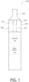
- the electronic vaporizer 100 can include a power source 110, a controller 120, an atomizer 130, and a mouthpiece 140.
- the atomizer 130 can include a first heating element 132 generally positioned within an air channel 134 leading to the mouthpiece 140. Further, the first heating element 132 can be in fluid communication with a fluid 138 held in a chamber, tank or other container 136. As discussed in greater detail below, a wicking material or other delivery mechanism can be employed to convey fluid 138 from the container 136 to a location proximate to the first heating element 132.
- Fluid 138 which is deposited near or in contact with the first heating element 132, boils and transitions to a vapor when the first heating element 132 is heated via electrical power provided by power source 110 and regulated by controller 120.
- the vapor once generated, can be drawn up the air channel 134 by an air flow created by a user via the mouthpiece 140. While referred to herein as a vapor, it is to be appreciated that, in some examples, the output of the electronic vaporizer 100 is an aerosol mist form of fluid 138.
- One parameter or characteristic on which user experience with the electronic vaporizer 100 is based includes an amount or quantity of vapor generated.
- This parameter generally corresponds to a power input (e.g., wattage) to the heating element 132.
- the controller 120 can ensure a substantially consistent and uniform vapor production and, therefore, consistent user experience, by regulating the power input from power source 110 to the first heating element 132 to maintain a preset level.
- the preset level can be established by the user via input means (not shown) of the electronic vaporizer 100 such as buttons, switches, etc.
- the preset level can also be displayed on a display screen (not shown) of the electronic vaporizer 100.
- controller 120 can measure at least two of the following: a resistance of the first heating element 132, a voltage applied to the first heating element 132, or a current supplied to the first heating element 132. From these measures, the controller 120 can determine an actual power output of the first heating element 132 and adjust one of a voltage or current provided by power source 110 to maintain the power output to the preset level.
- a resistance of the first heating element 132 a voltage applied to the first heating element 132
- a current supplied to the first heating element 132 the controller 120 can determine an actual power output of the first heating element 132 and adjust one of a voltage or current provided by power source 110 to maintain the power output to the preset level.
- other control, measurement, and/or feedback schemes can be utilized provided such schemes result in a substantially constant power output to the first heating element 132.
- a quality of the vapor e.g., taste, feeling, etc.
- This parameter generally correlates to a temperature of the first heating element 132.
- Fluid 138 can be a mixture of propylene glycol, glycerin, water, nicotine, and flavorings. At a high temperature, these compounds can degrade into less flavorful materials, or potentially harmful substances.
- the controller 120 can determine the temperature of the first heating element 132 and control the power source 110 to prevent the temperature of the first heating element 132 from exceeding a set temperature. As with the preset power level described above, the set temperature is configurable by the user.
- temperature control can be implemented by utilizing a heating element comprising a material with a known, positive temperature coefficient of resistance.
- the controller 120 by measuring a relative change in resistance of the first heating element 132, can determine a relative change in temperature.
- a reference resistance e.g., an absolute resistance of the heating element at a known temperature
- the controller 120 can determine an average temperature of the first heating element 132 based on a measured resistance.
- the controller 120 limits a power output to prevent a further increase in temperature.
- fluid 138 containing nicotine similar to how the quantity of vapor generated correlates with power output of heating element 132, dosing may also correlate to the power output.
- the energy imparted to fluid 138 via the power output of the heating element 132 generates a vapor, which condenses to an aerosol upon entry into an airstream thereby transferring some of that energy to the airstream.
- the aerosol cools slightly.
- a user experience e.g., taste, feeling, etc.
- a hotter aerosol more power is delivered to the fluid 138.
- vapor productions which results in a larger does of nicotine.
- Yet another characteristic of user experience is an effect of the vapor (e.g., a physiological or psychological effect, a health effect, etc.).
- this characteristic can be a rate of absorption and/or an amount of absorption.
- this characteristic can relate to externalities of the vapor imposed on others in an environment. In either case, a property of the vapor relating to this characteristic is particle size.
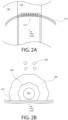
- first heating device 132 can be a heating coil at least partially positioned within the air channel 134.
- a wicking material 210 being in fluid communication with fluid 138, conveys fluid 138 to the first heating device 132, where the fluid 138 can be vaporized (more specifically, aerosolized).
- Fig. 2B depicts a cross-sectional view of a wire 202 of the first heating device 132.
- the wicking material 210 deposits a liquid phase layer 206 of fluid 138 around the wire 202.
- vapor phase layer 204 Due to the current carried by the wire 202, a portion of the liquid phase layer 206 is heated to a boiling point and transitions to a vapor, thereby creating a vapor phase layer 204. In response to air flow 220 through air channel 134, vapor in the vapor phase layer 204 is carried away from the wire 202. However, as the vapor phase layer 204 is substantially surrounded by the liquid phase layer 206, the vapor particles condense, cool, and increase in size. After transiting across the liquid phase layer 206, the vapor condenses to aerosol particles 208 having a larger particle size than the vapor particles of the vapor phase layer 204.
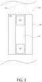
- Fig. 3 illustrates a schematic block diagram of an embodiment of an atomizer 300 configured to reduce the size of aerosol particles 208 produced by the first heating element 132.
- vapor/particle size is reduced with a two-stage heating structure.
- atomizer 300 includes a second heating element 310 at least partially disposed within the air channel 134.
- the second heating element 310 reheats or applies additional heat to the aerosol particles 208 carried by air flow 220 from the first heating element 132 to produce vapor and smaller aerosol particles.
- second heating element 310 super-heats a saturated low-quality vapor within the air flow 220. This vapor and smaller aerosol particles are carried out through the mouthpiece 140 to be inhaled by the user.
- the first heating element 132 implements a first stage where liquid fluid is heated to a heat of vaporization or boiling point to produce liquid droplets carried by air flow 220.
- the second heating element 310 implements a second stage where the liquid droplets are heated again to produce vapor and/or fine droplets.
- the second heating element 310 can be substantially similar to the first heating element 132.
- the second heating element 310 can be a heating coil substantially similar to the heating coil illustrated in Figs. 2A and 2B . It is to be appreciated that the second heating element 310 is not associated with a wicking material since a heating target, i.e. the saturated vapor, for the second heating element 310 is conveyed to the heating coil by air flow 220.
- the second heating element 310 facilitates output of a finer aerosol (e.g., an aerosol having a reduced particle size), which leads to improved absorption.
- the second heating element 310 also facilitates improving the quality of the vapor (e.g., taste, feel, etc.) by increasing a temperature of the output aerosol.
- the improved vapor quality can occur without a corresponding increase in dosing.
- atomizer 300 may be applicable for smoking cessation purposes. For instance, a traditional cigarette may deliver approximately between 20 and 30 watts to heat the air and smoke passing through. An atomizer providing less than this range generates an output (i.e. aerosol) cooler and weaker, in comparison, to a user.
- increasing the power output of the atomizer to produce an equivalent aerosol, from a user experience perspective, to a traditional cigarette would increase the dosing of nicotine.
- the second heating element 310 adds more total energy to the aerosol without producing a larger quantity of vapor or aerosol. In other words, the amount of vapor produced is decoupled from the quality of the vapor. That is, the first heating element 132 controls an amount of vapor generated and the second heating element 310 controls the temperature of the vapor independently from the amount generated. With the second heating element 310, a satisfying user experience is achievable while consuming smaller amounts of fluid 138. Accordingly, from a cessation perspective, the dosing of nicotine can be reduced through use of atomizer 300 without sacrificing user experience or satisfaction.
- the second heating element 310 can be controlled, via controller 120 for example, with similar techniques as the first heating element 132.
- the second heating element 310 can be temperature controlled and/or power (wattage) controlled by controller 120 via the techniques described above.
- a reference resistance for the second heating element 310 can be established.
- the reference resistance in an example, can be a resistance of the second heating element 310 at a cold temperature relative to an operating temperature of the atomizer 300 such as, but not limited to, a resistance at room temperature.
- the second heating element 310 can have known resistance characteristics versus temperature. Accordingly, a relative change in measured resistance can be translated into a relative change in temperature.
- the controller 120 can determine an actual average temperature of the second heating element 310. By monitoring the average temperature of the second heating element 310, the controller 120 can limit temperature to prevent heating the vapor high enough to negatively impact taste, produce undesirable compounds, or to increase a temperature of mouthpiece 140 (or other parts of the electronic vaporizer 100).
- System 400 includes a portion of electronic vaporizer 100 and, specifically, includes an atomizer 402 and controller 120. As shown, atomizer 402 can be similar to atomizer 300 described above with having the first heating element 132 and the second heating element 310.
- Atomizer 402 includes a connector 410 to facilitate removably coupling the atomizer 402 to other components of the electronic vaporizer 100 such as controller 120 and/or power source 110.
- connector 410 can be at least a three-pin adapter such as, but not limited to, a coaxial connector having at least three conductor rings. It is to be appreciated that connector 410 can be other form factors and/or include more or less pins, conductors, communication paths, lines, etc.
- a first pin can carry current or provide power to first heating element 132
- a second pin can carry current or provide power to second heating element 310
- a third pin can be a return path or ground connection. The third pin can be shared by both the first heating element 132 and the second heating element 310.
- Memory 402 can be an electrically erasable/programmable read-only memory (EEPROM); however, it is to be appreciated that memory 402 can be other forms of memory such as flash memory, other forms of ROM, or the like.
- Memory 402 can store a first reference resistance associated with the first heating element 132 and a second reference resistance associated with the second heating element 310. Further, memory 402 can include a user-space to store user-configurable settings such as, but not limited to, a power setting for the first heating element 132, a power setting for the second heating element 310, a temperature setting for the first heating element 132, a temperature setting for the second heating element 310, etc.
- Memory 402 enables atomizer 402 to be pre-initialized or preconfigured for temperature control by storing reference resistances.
- memory 402 enables atomizer 402 to be swapped with another similar atomizer (e.g., containing a different fluid) and the controller 120 can read memory 402 to automatically configure power control, temperature control, etc.
- the references stored in memory may be stored based on the type of atomizer 402 including but not limited to the volume of the atomizer, liquid type, flavor or other characteristic such that customized or stored settings may be defined for a given atomizer 402. These settings may be based on defined settings from a manufacturer or based on custom settings stored through user input.
- control circuit 500 that implements temperature control. Specifically, control circuit 500 prevents an average temperature of a heating element 506 from exceeding a predetermined temperature (e.g., a statutory limit or the like). Circuit 500 includes a power source 502 and a current source 504 which outputs a constant current to the heating element 506. As discussed above, resistance changes with temperature. Thus, the resistance of the heating element 506 increases as temperature increases. Since current source 504 outputs a constant current, the increase in resistance increases the output voltage to the heating element 506.
- a predetermined temperature e.g., a statutory limit or the like.
- circuit 500 includes a voltage sensor 508, which can be a voltage divider, for example, or substantially any component capable of outputting a measured output voltage.
- the voltage sensor 508 provides the measured output voltage to a comparator 510 for comparison to the reference voltage.
- the comparator 510 provides a feedback signal to the current source 504 to reduce power and lower the temperature.
- current source 504 can be implemented with a switching regulator.
- the feedback signal can adjust a duty cycle of the switching regulator to limit temperature.
- the feedback signal can operate to shut off the current source 504 for a remainder of a period.
- the current source 504, the comparator 510, etc., reset for the next period and only shut off again if the comparator 510 trips.
- Circuit 500 can be utilized in place of controller 120 to implement temperature control for the first heating element 132 and/or the second heating element 310.
- a cold resistance e.g., a room temperature resistance, or the like
- a range of cold resistances can be associated with a range of hot temperatures around the threshold temperature.
- a threshold resistance is known. Based on the known resistance/temperature characteristics of the heating element material, this threshold resistance is correlated to a temperature based on the measured cold resistance.
- the first heating element 132 and/or second heating element 310 can be manufactured to a cold resistance that can increase to a temperature sufficient to operate the electronic vaporizer 100 without tripping the comparator 510. Further, the heating elements 132, 310 can be manufactured such to cold resistances that will not result in the threshold resistance at a temperature exceeding the threshold temperature.
- tank 602 for holding a fluid (e.g., fluid 138) is illustrated.
- tank 602 is a toroid having a hollow extending axially through the tank 602.
- tank 602 fits around a base 612 of an atomizer having a heating element 604 positioned in an air channel and a connector 606 for coupling the heating element 604 to a controller and/or power source.
- a wicking material 608 is provided to convey the fluid from tank 602 to the heating element 604.
- a set of valves 610 are provided to bring the wicking material 608 into fluid communication with the contents of tank 602.
- base 612 can include a set of protrusions to respective ends of the wicking material 608 are mounted.
- the protrusions open features on tank 602 to enable the fluid to flow.
- the protrusions retract and the features on tank 602 seal.
- Fig. 7 illustrates an exemplary, non-limiting embodiment of a heating element 700 according to one or more aspects.
- heating element 700 is substantially cylindrical having an outer cylinder 702 and an inner cylinder 704.
- outer cylinder 702 is a thin foil having a plurality of apertures 706, which can be laser drilled to a diameter determined based on at least surface tension properties of fluid utilized with electronic vaporizers.
- the inner cylinder 704, according to an aspect, can be similar constructed; however, it is to be appreciated that inner cylinder 704 can be formed of a similar material as other heating elements described herein and/or conventionally used with electronic vaporizers.
- the outer cylinder 702 and inner cylinder 704 are maintained in a spaced relationship by spacers 708.
- the distance maintained between the outer cylinder 702 and the inner cylinder 704 is determined based on fluid properties and a minimum operating temperature of heating element 700. For instance, the distance is established by spacers 708 such that, as the temperature approaches the minimum operating temperature, the viscosity of the fluid decreases to enable the fluid to flow into a gap between the outer cylinder 702 and inner cylinder 704 by capillary action (see Fig. 7C ).
- the spacing established between the outer cylinder 702 and inner cylinder 704 may be configured such that a resultant capillary height (e.g., a height of the fluid column) for a particular fluid is greater than a height of the atomizer (i.e., heating element 700).
- a resultant capillary height e.g., a height of the fluid column
- the heating coil can be self-feeding with fluid from a reservoir.
- a current is carried by the inner cylinder 704 to generate heat to vaporize the fluid.
- the plurality of apertures 706 on the outer cylinder 702 render the outer cylinder 702 semi-permeable such that a vapor phase of the fluid can pass the barrier, but a liquid phase cannot.
- the vaporized fluid can pass through the outer cylinder 702 and into an air flow.
- the inner cylinder 704 and the outer cylinder 702 can be connected such that the current is carried into the heating element 700 via the inner cylinder 704 and carried out via the outer cylinder 702.
- the heating element 700 can be utilized in connection with the removable tank 602 described above.
- the protrusions on the base 612 can open into channels connected heating element 700 and, specifically, the gap between the inner cylinder 704 and the outer cylinder 702.
- another wickless fluid delivery system can involve a pump (e.g., a peristaltic pump) that conveys fluid through tubing to a spray bar positioned relative to a heating plate.
- the spray bar applies the fluid to the heating plate for vaporization.
- the heated plate can be a curved plate having a half-moon or semi-circular cross-section. That is, the curved plate can be a half-cylinder or half-pipe.
- the spray bar can extend along an axis of the curved plate and direct fluid radial outward to the heating plate.
- a device in one embodiment, includes a first heating element for heating a fluid to produce a first aerosol having a first particle size.
- the device further includes a second heating element for heating the first aerosol to generate a second aerosol having a second particle size.
- a primary dimension of the second particle size is less than a primary dimension of the first particle size.
- at least one of the first heating coil or the second heating coil are replaceable portions of the device.
- the device is a two-stage atomizer removably coupleable to an electronic vaporizer device having a power source and control electronics.
- the device can include a power source for providing electrical power to the first heating element and the second heating element and a control circuit for regulating the supply of electrical power to the first heating element and the second heating element.
- the device can include a connector for electrically coupling at least the first heating element and the second heating element to at least one of the power source or the control circuit.
- the control circuit can include a processor-based controller configured to monitor a temperature of at least one of the first heating element or the second heating element and to regulate the temperature of the at least one of the first heating element or the second heating element, the control circuit regulates the temperature to prevent the temperature from exceeding a limit.
- the control circuit includes a constant current source and a voltage comparator, the voltage comparator interrupts the constant current source when a measured output voltage to at least one of the first heating element or the second heating element exceeds a predetermined threshold.
- the predetermined threshold can correspond to a resistance value associated with a temperature limit of the at least one of the first heating element or the second heating element.
- the device can include a container for storing a fluid and means for conveying the fluid from the container to the first heating element.
- the container can be removably attached to the means for conveying.
- the device can include a memory.
- the memory stores at least one of a first resistance reference associated with the first heating element or a second resistance reference associated with the second heating element, the first resistance reference and the second resistance reference respectively indicate a resistance of a respective heating element at a predetermined temperature.
- the memory stores at least one of a first temperature coefficient of resistance (TCR) curve associated with the first heating element, a first temperature-resistance transfer function associated with the first heating element, a second TCR curve associated with the second heating element, or a second temperature-resistance transfer function associated with the second heating element.
- the memory can store values for user-configurable parameters.
- the user-configurable parameters include one or more of a power setting for the first heating element, a power setting for the second heating element, a temperature limit for the first heating element, or a temperature limit for the second heating element.
- an atomizer for an electronic vaporizer includes a first heating element for heating a fluid to produce a vapor.
- the first heating element has a first controllable power output to generate a correspondingly controllable quantity of the vapor.
- the atomizer further includes a second heating element for heating the vapor, delivered via an airstream from the first heating element, to generate an output vapor.
- the second heating element has a second controllable power output to generate a correspondingly controllable temperature of the output vapor.
- the first controllable power output and the second controllable power output are independently controlled such that the quantity of the vapor is decoupled from the temperature of the output vapor.
- a method for an electronic vaporizer can include controlling a first power output of a first heating element of an atomizer to generate a quantity of vapor from a fluid in contact with the first heating element.
- the method further includes controlling a second power output a second heating element, separated from the first heating element along an airstream, to increase a temperature of the quantity of vapor delivered to the second heating element via the airstream.
- the first power output and the second power output can be independently controlled.
- the term "or” is intended to mean an inclusive “or” rather than an exclusive “or.” That is, unless specified otherwise, or clear from the context, the phrase “X employs A or B” is intended to mean any of the natural inclusive permutations. That is, the phrase “X employs A or B” is satisfied by any of the following instances: X employs A; X employs B; or X employs both A and B.
- the terms “may” and “may be” indicate a possibility of an occurrence within a set of circumstances; a possession of a specified property, characteristic or function; and/or qualify another verb by expressing one or more of an ability, capability, or possibility associated with the qualified verb. Accordingly, usage of “may” and “may be” indicates that a modified term is apparently appropriate, capable, or suitable for an indicated capacity, function, or usage, while taking into account that in some circumstances the modified term may sometimes not be appropriate, capable, or suitable. For example, in some circumstances an event or capacity can be expected, while in other circumstances the event or capacity cannot occur - this distinction is captured by the terms “may” and “may be.”
Landscapes
- Health & Medical Sciences (AREA)
- Engineering & Computer Science (AREA)
- Anesthesiology (AREA)
- Biomedical Technology (AREA)
- Heart & Thoracic Surgery (AREA)
- Hematology (AREA)
- Life Sciences & Earth Sciences (AREA)
- Animal Behavior & Ethology (AREA)
- General Health & Medical Sciences (AREA)
- Public Health (AREA)
- Veterinary Medicine (AREA)
- Bioinformatics & Cheminformatics (AREA)
- Pulmonology (AREA)
- Catching Or Destruction (AREA)
- Control Of Resistance Heating (AREA)
Claims (15)
- Zerstäuber (130) für einen elektronischen Verdampfer (100), umfassend:ein erstes Heizelement (132) zum Erwärmen eines Fluids, um einen Dampf zu erzeugen, wobei das erste Heizelement (132) einen ersten steuerbaren Leistungsausgang aufweist, um eine entsprechend steuerbare Menge des Dampfes zu erzeugen;ein Dochtmaterial (210) zum Fördern des Fluids von einem Behälter zu dem ersten Heizelement (132);ein zweites Heizelement (310) zum Erwärmen des Dampfes, das nicht mit einem weiteren Dochtmaterial assoziiert ist, sondern über einen Luftstrom von dem ersten Heizelement (132) zugeführt wird, um einen Ausgangsdampf zu erzeugen, wobei das zweite Heizelement (310) einen zweiten steuerbaren Leistungsausgang aufweist, um eine entsprechend steuerbare Temperatur des Ausgangsdampfes zu erzeugen.
- Zerstäuber nach Anspruch 1, wobei der erste steuerbare Leistungsausgang und der zweite steuerbare Leistungsausgang unabhängig gesteuert werden, so dass die Dampfmenge von der Temperatur des Ausgangsdampfes entkoppelt ist.
- Vorrichtung, die einen elektronischen Verdampfer (100) bereitstellt und den Zerstäuber (130) nach Anspruch 1 einschließt, wobei:das erste Heizelement (132) zum Erwärmen eines Fluids dient, um ein erstes Aerosol mit einer ersten Partikelgröße zu erzeugen; unddas zweite Heizelement (310) zum Erwärmen des ersten Aerosols dient, um ein zweites Aerosol mit einer zweiten Partikelgröße zu erzeugen,wobei eine primäre Abmessung der zweiten Partikelgröße kleiner als eine primäre Abmessung der ersten Partikelgröße ist,wobei die Vorrichtung ferner einen Luftkanal zwischen dem ersten Heizelement (132) und dem zweiten Heizelement (310) umfasst,wobei der Luftkanal einen Luftstrom leitet, um das erste Aerosol zu dem zweiten Heizelement (310) zu transportieren,wobei die Vorrichtung ferner umfasst:eine Stromquelle (110) zum Bereitstellen von elektrischer Leistung an das erste Heizelement (132) und das zweite Heizelement (310); undeine Steuerschaltung zum Regeln der Zufuhr von elektrischer Leistung an das erste Heizelement (132) und das zweite Heizelement (310),wobei die Vorrichtung ferner umfasst:einen Behälter zum Speichern eines Fluids;wobei das zweite Heizelement (310) zumindest teilweise in dem Luftkanal angeordnet ist, wobei das zweite Heizelement (310) das erste Aerosol, das durch den Luftstrom in dem Luftkanal von dem ersten Heizelement (132) transportiert wird, wiedererwärmt, um Dampf und kleinere Aerosolpartikel zu erzeugen,wobei das erste Aerosol durch den Luftstrom in dem Luftkanal zu dem zweiten Heizelement (310) befördert wird,wobei der erste steuerbare Leistungsausgang und der zweite steuerbare Leistungsausgang unabhängig gesteuert werden.
- Vorrichtung (100) nach Anspruch 3, die ferner einen Verbinder zum elektrischen Koppeln mindestens des ersten Heizelements (132) und des zweiten Heizelements (310) mit mindestens der Stromquelle oder der Steuerschaltung umfasst.
- Vorrichtung (100) nach Anspruch 3, wobei die Steuerschaltung eine prozessorbasierte Steuerung (120) umfasst, die konfiguriert ist, um eine Temperatur von mindestens einem zwischen dem ersten Heizelement (132) oder dem zweiten Heizelement (310) zu überwachen und die Temperatur des mindestens einen zwischen dem ersten Heizelement (132) oder dem zweiten Heizelement (310) zu regeln.
- Vorrichtung (100) nach Anspruch 5, wobei die Steuerschaltung die Temperatur regelt, um zu verhindern, dass die Temperatur einen Grenzwert überschreitet.
- Vorrichtung (100) nach Anspruch 3, wobei die Steuerschaltung eine Konstantstromquelle und einen Spannungskomparator umfasst, wobei der Spannungskomparator die Konstantstromquelle unterbricht, wenn eine gemessene Ausgangsspannung an mindestens einem zwischen dem ersten Heizelement (132) oder dem zweiten Heizelement (310) einen vorbestimmten Schwellenwert überschreitet.
- Vorrichtung (100) nach Anspruch 7, wobei der vorbestimmte Schwellenwert einem Widerstandswert entspricht, der mit einer Temperaturgrenze des mindestens einen des ersten Heizelements (132) oder des zweiten Heizelements (310) assoziiert ist.
- Vorrichtung (100) nach Anspruch 7, wobei der Behälter abnehmbar an den Fördermitteln angebracht ist.
- Vorrichtung (100) nach Anspruch 3, die ferner einen Speicher (402) umfasst.
- Vorrichtung (100) nach Anspruch 10, wobei der Speicher (402) mindestens eine erste Widerstandsreferenz, die mit dem ersten Heizelement (132) assoziiert ist, oder eine zweite Widerstandsreferenz, die mit dem zweiten Heizelement (310) assoziiert ist, speichert, wobei die erste Widerstandsreferenz und die zweite Widerstandsreferenz jeweils einen Widerstand eines jeweiligen Heizelements bei einer vorbestimmten Temperatur anzeigen.
- Vorrichtung (100) nach Anspruch 10, wobei der Speicher (402) mindestens eine unter einer ersten Temperaturkoeffizient-(TCR)-Widerstandskurve, die mit dem ersten Heizelement (132) assoziiert ist, einer ersten Temperaturwiderstandsübertragungsfunktion, die mit dem ersten Heizelement (132) assoziiert ist, einer zweiten TCR-Kurve, die mit dem zweiten Heizelement (310) assoziiert ist, oder einer zweiten Temperaturwiderstandsübertragungsfunktion, die mit dem zweiten Heizelement (310) assoziiert ist, speichert.
- Vorrichtung (100) nach Anspruch 10, wobei der Speicher Werte für vom Benutzer konfigurierbare Parameter speichert.
- Vorrichtung (100) nach Anspruch 13, wobei die vom Benutzer konfigurierbaren Parameter eine oder mehrere zwischen einer Leistungseinstellung für das erste Heizelement (132), einer Leistungseinstellung für das zweite Heizelement (310), einer Temperaturgrenze für das erste Heizelement (132) oder einer Temperaturgrenze für das zweite Heizelement (310) einschließen.
- Vorrichtung (100) nach Anspruch 3, wobei das erste Heizelement und/oder das zweite Heizelement austauschbare Abschnitte der Vorrichtung sind.
Applications Claiming Priority (1)
| Application Number | Priority Date | Filing Date | Title |
|---|---|---|---|
| PCT/US2015/035154 WO2016200382A1 (en) | 2015-06-10 | 2015-06-10 | Electronic vaporizer having reduced particle size |
Publications (2)
| Publication Number | Publication Date |
|---|---|
| EP3283149A1 EP3283149A1 (de) | 2018-02-21 |
| EP3283149B1 true EP3283149B1 (de) | 2023-08-02 |
Family
ID=53443032
Family Applications (1)
| Application Number | Title | Priority Date | Filing Date |
|---|---|---|---|
| EP15730646.5A Active EP3283149B1 (de) | 2015-06-10 | 2015-06-10 | Elektronischer verdampfer mit reduzierter partikelgrösse |
Country Status (4)
| Country | Link |
|---|---|
| EP (1) | EP3283149B1 (de) |
| CN (1) | CN107635417A (de) |
| HK (1) | HK1249994A1 (de) |
| WO (1) | WO2016200382A1 (de) |
Cited By (1)
| Publication number | Priority date | Publication date | Assignee | Title |
|---|---|---|---|---|
| US12520880B2 (en) | 2021-01-18 | 2026-01-13 | Altria Client Services Llc | Heat-not-burn (HNB) aerosol-generating devices including energy based heater control, and methods of controlling a heater |
Families Citing this family (35)
| Publication number | Priority date | Publication date | Assignee | Title |
|---|---|---|---|---|
| US20160345631A1 (en) | 2005-07-19 | 2016-12-01 | James Monsees | Portable devices for generating an inhalable vapor |
| US10279934B2 (en) | 2013-03-15 | 2019-05-07 | Juul Labs, Inc. | Fillable vaporizer cartridge and method of filling |
| PT3508080T (pt) | 2013-12-23 | 2021-03-02 | Juul Labs Int Inc | Sistemas e métodos de dispositivo de vaporização |
| USD825102S1 (en) | 2016-07-28 | 2018-08-07 | Juul Labs, Inc. | Vaporizer device with cartridge |
| USD842536S1 (en) | 2016-07-28 | 2019-03-05 | Juul Labs, Inc. | Vaporizer cartridge |
| US10159282B2 (en) | 2013-12-23 | 2018-12-25 | Juul Labs, Inc. | Cartridge for use with a vaporizer device |
| US10076139B2 (en) | 2013-12-23 | 2018-09-18 | Juul Labs, Inc. | Vaporizer apparatus |
| US10058129B2 (en) | 2013-12-23 | 2018-08-28 | Juul Labs, Inc. | Vaporization device systems and methods |
| US20160366947A1 (en) | 2013-12-23 | 2016-12-22 | James Monsees | Vaporizer apparatus |
| CN112155255B (zh) | 2014-12-05 | 2025-10-28 | 尤尔实验室有限公司 | 校正剂量控制 |
| CN115299642A (zh) | 2015-07-10 | 2022-11-08 | 尤尔实验室有限公司 | 无芯汽化装置及方法 |
| EP3413960B1 (de) | 2016-02-11 | 2021-03-31 | Juul Labs, Inc. | Füllbare verdampferkartusche und verfahren zum füllen |
| SG11201806801VA (en) | 2016-02-11 | 2018-09-27 | Juul Labs Inc | Securely attaching cartridges for vaporizer devices |
| US10405582B2 (en) | 2016-03-10 | 2019-09-10 | Pax Labs, Inc. | Vaporization device with lip sensing |
| USD849996S1 (en) | 2016-06-16 | 2019-05-28 | Pax Labs, Inc. | Vaporizer cartridge |
| USD851830S1 (en) | 2016-06-23 | 2019-06-18 | Pax Labs, Inc. | Combined vaporizer tamp and pick tool |
| USD836541S1 (en) | 2016-06-23 | 2018-12-25 | Pax Labs, Inc. | Charging device |
| CN109789285B (zh) | 2016-08-05 | 2023-01-20 | 尤尔实验室有限公司 | 蒸发器的风速辅助控制 |
| USD887632S1 (en) | 2017-09-14 | 2020-06-16 | Pax Labs, Inc. | Vaporizer cartridge |
| CN109587840A (zh) * | 2018-05-21 | 2019-04-05 | 深圳市卓力能电子有限公司 | 一种电子烟加热元件的加热方法及电子烟加热元件 |
| US11666086B2 (en) | 2018-05-29 | 2023-06-06 | Juul Labs, Inc. | Vaporizer cartridge for a vaporizer |
| IT201800006391A1 (it) * | 2018-06-18 | 2019-12-18 | Sistema per la vaporizzazione molecolare di una sostanza liquida | |
| US10986875B2 (en) | 2018-06-25 | 2021-04-27 | Juul Labs, Inc. | Vaporizer device heater control |
| CN109330027B (zh) * | 2018-08-24 | 2022-10-21 | 深圳麦克韦尔科技有限公司 | 电子烟具及其控制方法、发热组件、电子设备及存储介质 |
| US11413409B2 (en) | 2018-09-12 | 2022-08-16 | Juul Labs, Inc. | Vaporizer including positive temperature coefficient of resistivity (PTCR) heating element |
| EP3628354A1 (de) | 2018-09-27 | 2020-04-01 | Ttp Plc. | Aerosolabgabesystem mit perforierter membran |
| US11614720B2 (en) | 2018-11-19 | 2023-03-28 | Rai Strategic Holdings, Inc. | Temperature control in an aerosol delivery device |
| US12066654B2 (en) | 2018-11-19 | 2024-08-20 | Rai Strategic Holdings, Inc. | Charging control for an aerosol delivery device |
| US11592793B2 (en) | 2018-11-19 | 2023-02-28 | Rai Strategic Holdings, Inc. | Power control for an aerosol delivery device |
| DE102018130105A1 (de) | 2018-11-28 | 2020-05-28 | Hauni Maschinenbau Gmbh | Verfahren und Vorrichtung zur Temperaturregelung eines Verdampfers für einen Inhalator, insbesondere ein elektronisches Zigarettenprodukt |
| KR102199793B1 (ko) * | 2018-12-11 | 2021-01-07 | 주식회사 케이티앤지 | 에어로졸 생성 장치 |
| CN212590266U (zh) * | 2019-10-29 | 2021-02-26 | 深圳麦克韦尔科技有限公司 | 电子雾化装置 |
| CN116548685B (zh) * | 2023-04-27 | 2025-11-18 | 深圳市太美亚电子科技有限公司 | 一种加热均匀的电子雾化器 |
| CN120899034B (zh) * | 2025-07-09 | 2026-06-30 | 东莞市麦斯莫科电子科技有限公司 | 空气加热式加热不燃烧电子烟及其温度控制方法 |
| CN120960564A (zh) * | 2025-09-11 | 2025-11-18 | 广东伊诗图电子科技有限公司 | 一种便携式雾化器及其雾化方法 |
Family Cites Families (19)
| Publication number | Priority date | Publication date | Assignee | Title |
|---|---|---|---|---|
| US5144962A (en) * | 1989-12-01 | 1992-09-08 | Philip Morris Incorporated | Flavor-delivery article |
| US6501052B2 (en) * | 2000-12-22 | 2002-12-31 | Chrysalis Technologies Incorporated | Aerosol generator having multiple heating zones and methods of use thereof |
| EP2113178A1 (de) * | 2008-04-30 | 2009-11-04 | Philip Morris Products S.A. | Elektrisch beheiztes Rauchsystem mit einem Element zur Flüssigkeitsspeicherung |
| EP2327318A1 (de) * | 2009-11-27 | 2011-06-01 | Philip Morris Products S.A. | Elektrisch erhitztes Rauchsystem mit interner oder externer Heizvorrichtung |
| EP2468117A1 (de) * | 2010-12-24 | 2012-06-27 | Philip Morris Products S.A. | Aerosolerzeugungssystem mit Mitteln zur Bestimmung der Erschöpfung eines Flüssigsubstrats |
| KR102671442B1 (ko) * | 2011-09-06 | 2024-05-30 | 니코벤처스 트레이딩 리미티드 | 가열식 끽연 가능 물질 |
| KR102032102B1 (ko) * | 2011-12-30 | 2019-10-14 | 필립모리스 프로덕츠 에스.에이. | 공기 흐름 검출을 구비하는 에어로졸 발생 장치 |
| AU2012360817B2 (en) * | 2011-12-30 | 2017-09-07 | Philip Morris Products S.A. | Aerosol generating device with improved temperature distribution |
| US9282772B2 (en) * | 2012-01-31 | 2016-03-15 | Altria Client Services Llc | Electronic vaping device |
| CN104254258B (zh) * | 2012-04-12 | 2018-11-30 | Jt国际公司 | 浮质发生装置 |
| US10004259B2 (en) * | 2012-06-28 | 2018-06-26 | Rai Strategic Holdings, Inc. | Reservoir and heater system for controllable delivery of multiple aerosolizable materials in an electronic smoking article |
| PL2925395T3 (pl) * | 2012-11-28 | 2019-08-30 | Fontem Holdings 1 B.V. | Urządzenie wytwarzające aerozol kondensacyjny z ciekłej formulacji |
| CN103251134B (zh) * | 2013-05-20 | 2015-07-15 | 西安拓尔微电子有限责任公司 | 一种新型的电子烟控制芯片 |
| UA120351C2 (uk) * | 2013-05-21 | 2019-11-25 | Філіп Морріс Продактс С.А. | Система подачі аерозолю, яка нагрівається за допомогою електричного струму |
| CN203643774U (zh) * | 2013-12-13 | 2014-06-11 | 深圳市合元科技有限公司 | 电子烟 |
| CN203748667U (zh) * | 2013-12-24 | 2014-08-06 | 深圳市合元科技有限公司 | 电子烟用雾化器及电子烟 |
| CN203748670U (zh) * | 2013-12-30 | 2014-08-06 | 深圳市合元科技有限公司 | 烘焙型雾化器及电子烟 |
| CN104122179B (zh) * | 2014-08-05 | 2017-03-22 | 云南中烟工业有限责任公司 | 一种评价电子烟烟雾量的方法 |
| CN204146307U (zh) * | 2014-08-12 | 2015-02-11 | 刘水根 | 一种电子烟草蒸发器 |
-
2015
- 2015-06-10 EP EP15730646.5A patent/EP3283149B1/de active Active
- 2015-06-10 WO PCT/US2015/035154 patent/WO2016200382A1/en not_active Ceased
- 2015-06-10 HK HK18109512.0A patent/HK1249994A1/zh unknown
- 2015-06-10 CN CN201580079948.3A patent/CN107635417A/zh active Pending
Cited By (1)
| Publication number | Priority date | Publication date | Assignee | Title |
|---|---|---|---|---|
| US12520880B2 (en) | 2021-01-18 | 2026-01-13 | Altria Client Services Llc | Heat-not-burn (HNB) aerosol-generating devices including energy based heater control, and methods of controlling a heater |
Also Published As
| Publication number | Publication date |
|---|---|
| HK1249994A1 (zh) | 2018-11-23 |
| CN107635417A (zh) | 2018-01-26 |
| WO2016200382A1 (en) | 2016-12-15 |
| EP3283149A1 (de) | 2018-02-21 |
Similar Documents
| Publication | Publication Date | Title |
|---|---|---|
| US12156299B2 (en) | Electronic vaporizer having reduced particle size | |
| EP3283149A1 (de) | Elektronischer verdampfer mit reduzierter partikelgrösse | |
| US12133296B2 (en) | Electronic vaporizer having temperature sensing and limit | |
| US11617395B2 (en) | Aerosol-generating device and method for controlling a heater of an aerosol-generating device | |
| KR102052713B1 (ko) | 히터를 구비한 에어로졸 생성 장치 | |
| CA2851933C (en) | Aerosol generating system with improved aerosol production | |
| KR102628153B1 (ko) | 맞춤형 식별 저항을 갖는 에어로졸 발생 시스템용 카트리지 | |
| KR102624338B1 (ko) | 에어로졸 형성 조성물의 생성 | |
| US10512285B2 (en) | Method of controlling aerosol production to control aerosol properties | |
| CN101977522B (zh) | 用于控制电气烟雾生成系统中烟气成分的形成的方法 | |
| JP7480159B2 (ja) | 吸入装置における温度を制御するための装置および方法 | |
| CN107692316B (zh) | 加热式气溶胶产生装置及产生特性一致的气溶胶的方法 | |
| US10470496B2 (en) | Device and method for controlling an electrical heater to limit temperature according to desired temperature profile over time | |
| JP2022554063A (ja) | ヒーター制御を備えた電子タバコ装置 | |
| CA3042149A1 (en) | Aerosol-generating device | |
| GB2537121A (en) | Inhalation device | |
| KR102052715B1 (ko) | 히터를 구비한 에어로졸 생성 장치 | |
| KR102065073B1 (ko) | 히터를 구비한 에어로졸 생성 장치 | |
| TW202121999A (zh) | 電子煙 | |
| HK1232744A1 (en) | Electronic vaporizer having temperature sensing and limit | |
| HK40030312A (en) | Aerosol-generating device and method for controlling a heater of an aerosol-generating device |
Legal Events
| Date | Code | Title | Description |
|---|---|---|---|
| STAA | Information on the status of an ep patent application or granted ep patent |
Free format text: STATUS: THE INTERNATIONAL PUBLICATION HAS BEEN MADE |
|
| PUAI | Public reference made under article 153(3) epc to a published international application that has entered the european phase |
Free format text: ORIGINAL CODE: 0009012 |
|
| STAA | Information on the status of an ep patent application or granted ep patent |
Free format text: STATUS: REQUEST FOR EXAMINATION WAS MADE |
|
| 17P | Request for examination filed |
Effective date: 20171116 |
|
| AK | Designated contracting states |
Kind code of ref document: A1 Designated state(s): AL AT BE BG CH CY CZ DE DK EE ES FI FR GB GR HR HU IE IS IT LI LT LU LV MC MK MT NL NO PL PT RO RS SE SI SK SM TR |
|
| AX | Request for extension of the european patent |
Extension state: BA ME |
|
| DAV | Request for validation of the european patent (deleted) | ||
| DAX | Request for extension of the european patent (deleted) | ||
| STAA | Information on the status of an ep patent application or granted ep patent |
Free format text: STATUS: EXAMINATION IS IN PROGRESS |
|
| 17Q | First examination report despatched |
Effective date: 20200909 |
|
| GRAP | Despatch of communication of intention to grant a patent |
Free format text: ORIGINAL CODE: EPIDOSNIGR1 |
|
| STAA | Information on the status of an ep patent application or granted ep patent |
Free format text: STATUS: GRANT OF PATENT IS INTENDED |
|
| INTG | Intention to grant announced |
Effective date: 20220923 |
|
| GRAS | Grant fee paid |
Free format text: ORIGINAL CODE: EPIDOSNIGR3 |
|
| GRAA | (expected) grant |
Free format text: ORIGINAL CODE: 0009210 |
|
| STAA | Information on the status of an ep patent application or granted ep patent |
Free format text: STATUS: THE PATENT HAS BEEN GRANTED |
|
| AK | Designated contracting states |
Kind code of ref document: B1 Designated state(s): AL AT BE BG CH CY CZ DE DK EE ES FI FR GB GR HR HU IE IS IT LI LT LU LV MC MK MT NL NO PL PT RO RS SE SI SK SM TR |
|
| REG | Reference to a national code |
Ref country code: GB Ref legal event code: FG4D |
|
| REG | Reference to a national code |
Ref country code: CH Ref legal event code: EP |
|
| REG | Reference to a national code |
Ref country code: DE Ref legal event code: R096 Ref document number: 602015084895 Country of ref document: DE |
|
| REG | Reference to a national code |
Ref country code: IE Ref legal event code: FG4D |
|
| REG | Reference to a national code |
Ref country code: LT Ref legal event code: MG9D |
|
| REG | Reference to a national code |
Ref country code: NL Ref legal event code: MP Effective date: 20230802 |
|
| REG | Reference to a national code |
Ref country code: AT Ref legal event code: MK05 Ref document number: 1593935 Country of ref document: AT Kind code of ref document: T Effective date: 20230802 |
|
| PG25 | Lapsed in a contracting state [announced via postgrant information from national office to epo] |
Ref country code: GR Free format text: LAPSE BECAUSE OF FAILURE TO SUBMIT A TRANSLATION OF THE DESCRIPTION OR TO PAY THE FEE WITHIN THE PRESCRIBED TIME-LIMIT Effective date: 20231103 |
|
| PG25 | Lapsed in a contracting state [announced via postgrant information from national office to epo] |
Ref country code: IS Free format text: LAPSE BECAUSE OF FAILURE TO SUBMIT A TRANSLATION OF THE DESCRIPTION OR TO PAY THE FEE WITHIN THE PRESCRIBED TIME-LIMIT Effective date: 20231202 |
|
| PG25 | Lapsed in a contracting state [announced via postgrant information from national office to epo] |
Ref country code: SE Free format text: LAPSE BECAUSE OF FAILURE TO SUBMIT A TRANSLATION OF THE DESCRIPTION OR TO PAY THE FEE WITHIN THE PRESCRIBED TIME-LIMIT Effective date: 20230802 Ref country code: RS Free format text: LAPSE BECAUSE OF FAILURE TO SUBMIT A TRANSLATION OF THE DESCRIPTION OR TO PAY THE FEE WITHIN THE PRESCRIBED TIME-LIMIT Effective date: 20230802 Ref country code: PT Free format text: LAPSE BECAUSE OF FAILURE TO SUBMIT A TRANSLATION OF THE DESCRIPTION OR TO PAY THE FEE WITHIN THE PRESCRIBED TIME-LIMIT Effective date: 20231204 Ref country code: NO Free format text: LAPSE BECAUSE OF FAILURE TO SUBMIT A TRANSLATION OF THE DESCRIPTION OR TO PAY THE FEE WITHIN THE PRESCRIBED TIME-LIMIT Effective date: 20231102 Ref country code: NL Free format text: LAPSE BECAUSE OF FAILURE TO SUBMIT A TRANSLATION OF THE DESCRIPTION OR TO PAY THE FEE WITHIN THE PRESCRIBED TIME-LIMIT Effective date: 20230802 Ref country code: LV Free format text: LAPSE BECAUSE OF FAILURE TO SUBMIT A TRANSLATION OF THE DESCRIPTION OR TO PAY THE FEE WITHIN THE PRESCRIBED TIME-LIMIT Effective date: 20230802 Ref country code: LT Free format text: LAPSE BECAUSE OF FAILURE TO SUBMIT A TRANSLATION OF THE DESCRIPTION OR TO PAY THE FEE WITHIN THE PRESCRIBED TIME-LIMIT Effective date: 20230802 Ref country code: IS Free format text: LAPSE BECAUSE OF FAILURE TO SUBMIT A TRANSLATION OF THE DESCRIPTION OR TO PAY THE FEE WITHIN THE PRESCRIBED TIME-LIMIT Effective date: 20231202 Ref country code: HR Free format text: LAPSE BECAUSE OF FAILURE TO SUBMIT A TRANSLATION OF THE DESCRIPTION OR TO PAY THE FEE WITHIN THE PRESCRIBED TIME-LIMIT Effective date: 20230802 Ref country code: GR Free format text: LAPSE BECAUSE OF FAILURE TO SUBMIT A TRANSLATION OF THE DESCRIPTION OR TO PAY THE FEE WITHIN THE PRESCRIBED TIME-LIMIT Effective date: 20231103 Ref country code: FI Free format text: LAPSE BECAUSE OF FAILURE TO SUBMIT A TRANSLATION OF THE DESCRIPTION OR TO PAY THE FEE WITHIN THE PRESCRIBED TIME-LIMIT Effective date: 20230802 Ref country code: AT Free format text: LAPSE BECAUSE OF FAILURE TO SUBMIT A TRANSLATION OF THE DESCRIPTION OR TO PAY THE FEE WITHIN THE PRESCRIBED TIME-LIMIT Effective date: 20230802 |
|
| PG25 | Lapsed in a contracting state [announced via postgrant information from national office to epo] |
Ref country code: PL Free format text: LAPSE BECAUSE OF FAILURE TO SUBMIT A TRANSLATION OF THE DESCRIPTION OR TO PAY THE FEE WITHIN THE PRESCRIBED TIME-LIMIT Effective date: 20230802 |
|
| PG25 | Lapsed in a contracting state [announced via postgrant information from national office to epo] |
Ref country code: ES Free format text: LAPSE BECAUSE OF FAILURE TO SUBMIT A TRANSLATION OF THE DESCRIPTION OR TO PAY THE FEE WITHIN THE PRESCRIBED TIME-LIMIT Effective date: 20230802 |
|
| PG25 | Lapsed in a contracting state [announced via postgrant information from national office to epo] |
Ref country code: SM Free format text: LAPSE BECAUSE OF FAILURE TO SUBMIT A TRANSLATION OF THE DESCRIPTION OR TO PAY THE FEE WITHIN THE PRESCRIBED TIME-LIMIT Effective date: 20230802 Ref country code: RO Free format text: LAPSE BECAUSE OF FAILURE TO SUBMIT A TRANSLATION OF THE DESCRIPTION OR TO PAY THE FEE WITHIN THE PRESCRIBED TIME-LIMIT Effective date: 20230802 Ref country code: ES Free format text: LAPSE BECAUSE OF FAILURE TO SUBMIT A TRANSLATION OF THE DESCRIPTION OR TO PAY THE FEE WITHIN THE PRESCRIBED TIME-LIMIT Effective date: 20230802 Ref country code: EE Free format text: LAPSE BECAUSE OF FAILURE TO SUBMIT A TRANSLATION OF THE DESCRIPTION OR TO PAY THE FEE WITHIN THE PRESCRIBED TIME-LIMIT Effective date: 20230802 Ref country code: DK Free format text: LAPSE BECAUSE OF FAILURE TO SUBMIT A TRANSLATION OF THE DESCRIPTION OR TO PAY THE FEE WITHIN THE PRESCRIBED TIME-LIMIT Effective date: 20230802 Ref country code: CZ Free format text: LAPSE BECAUSE OF FAILURE TO SUBMIT A TRANSLATION OF THE DESCRIPTION OR TO PAY THE FEE WITHIN THE PRESCRIBED TIME-LIMIT Effective date: 20230802 Ref country code: SK Free format text: LAPSE BECAUSE OF FAILURE TO SUBMIT A TRANSLATION OF THE DESCRIPTION OR TO PAY THE FEE WITHIN THE PRESCRIBED TIME-LIMIT Effective date: 20230802 |
|
| REG | Reference to a national code |
Ref country code: DE Ref legal event code: R097 Ref document number: 602015084895 Country of ref document: DE |
|
| PLBE | No opposition filed within time limit |
Free format text: ORIGINAL CODE: 0009261 |
|
| STAA | Information on the status of an ep patent application or granted ep patent |
Free format text: STATUS: NO OPPOSITION FILED WITHIN TIME LIMIT |
|
| 26N | No opposition filed |
Effective date: 20240503 |
|
| PG25 | Lapsed in a contracting state [announced via postgrant information from national office to epo] |
Ref country code: SI Free format text: LAPSE BECAUSE OF FAILURE TO SUBMIT A TRANSLATION OF THE DESCRIPTION OR TO PAY THE FEE WITHIN THE PRESCRIBED TIME-LIMIT Effective date: 20230802 |
|
| PG25 | Lapsed in a contracting state [announced via postgrant information from national office to epo] |
Ref country code: BG Free format text: LAPSE BECAUSE OF FAILURE TO SUBMIT A TRANSLATION OF THE DESCRIPTION OR TO PAY THE FEE WITHIN THE PRESCRIBED TIME-LIMIT Effective date: 20230802 |
|
| PG25 | Lapsed in a contracting state [announced via postgrant information from national office to epo] |
Ref country code: BG Free format text: LAPSE BECAUSE OF FAILURE TO SUBMIT A TRANSLATION OF THE DESCRIPTION OR TO PAY THE FEE WITHIN THE PRESCRIBED TIME-LIMIT Effective date: 20230802 |
|
| PG25 | Lapsed in a contracting state [announced via postgrant information from national office to epo] |
Ref country code: MC Free format text: LAPSE BECAUSE OF FAILURE TO SUBMIT A TRANSLATION OF THE DESCRIPTION OR TO PAY THE FEE WITHIN THE PRESCRIBED TIME-LIMIT Effective date: 20230802 |
|
| REG | Reference to a national code |
Ref country code: CH Ref legal event code: PL |
|
| PG25 | Lapsed in a contracting state [announced via postgrant information from national office to epo] |
Ref country code: LU Free format text: LAPSE BECAUSE OF NON-PAYMENT OF DUE FEES Effective date: 20240610 |
|
| PG25 | Lapsed in a contracting state [announced via postgrant information from national office to epo] |
Ref country code: IE Free format text: LAPSE BECAUSE OF NON-PAYMENT OF DUE FEES Effective date: 20240610 |
|
| PG25 | Lapsed in a contracting state [announced via postgrant information from national office to epo] |
Ref country code: CH Free format text: LAPSE BECAUSE OF NON-PAYMENT OF DUE FEES Effective date: 20240630 Ref country code: BE Free format text: LAPSE BECAUSE OF NON-PAYMENT OF DUE FEES Effective date: 20240630 |
|
| REG | Reference to a national code |
Ref country code: BE Ref legal event code: MM Effective date: 20240630 |
|
| PGFP | Annual fee paid to national office [announced via postgrant information from national office to epo] |
Ref country code: IT Payment date: 20250612 Year of fee payment: 11 |
|
| PG25 | Lapsed in a contracting state [announced via postgrant information from national office to epo] |
Ref country code: CY Free format text: LAPSE BECAUSE OF FAILURE TO SUBMIT A TRANSLATION OF THE DESCRIPTION OR TO PAY THE FEE WITHIN THE PRESCRIBED TIME-LIMIT; INVALID AB INITIO Effective date: 20150610 |
|
| PG25 | Lapsed in a contracting state [announced via postgrant information from national office to epo] |
Ref country code: HU Free format text: LAPSE BECAUSE OF FAILURE TO SUBMIT A TRANSLATION OF THE DESCRIPTION OR TO PAY THE FEE WITHIN THE PRESCRIBED TIME-LIMIT; INVALID AB INITIO Effective date: 20150610 |
|
| PG25 | Lapsed in a contracting state [announced via postgrant information from national office to epo] |
Ref country code: TR Free format text: LAPSE BECAUSE OF FAILURE TO SUBMIT A TRANSLATION OF THE DESCRIPTION OR TO PAY THE FEE WITHIN THE PRESCRIBED TIME-LIMIT Effective date: 20230802 |
|
| PGFP | Annual fee paid to national office [announced via postgrant information from national office to epo] |
Ref country code: GB Payment date: 20260622 Year of fee payment: 12 |
|
| PGFP | Annual fee paid to national office [announced via postgrant information from national office to epo] |
Ref country code: DE Payment date: 20260623 Year of fee payment: 12 |
|
| PGFP | Annual fee paid to national office [announced via postgrant information from national office to epo] |
Ref country code: FR Payment date: 20260622 Year of fee payment: 12 |