EP3283231B1 - Système de changement de couleur - Google Patents
Système de changement de couleur Download PDFInfo
- Publication number
- EP3283231B1 EP3283231B1 EP16728214.4A EP16728214A EP3283231B1 EP 3283231 B1 EP3283231 B1 EP 3283231B1 EP 16728214 A EP16728214 A EP 16728214A EP 3283231 B1 EP3283231 B1 EP 3283231B1
- Authority
- EP
- European Patent Office
- Prior art keywords
- valve
- media
- stator
- selection head
- control channel
- Prior art date
- Legal status (The legal status is an assumption and is not a legal conclusion. Google has not performed a legal analysis and makes no representation as to the accuracy of the status listed.)
- Not-in-force
Links
Images




Classifications
-
- B—PERFORMING OPERATIONS; TRANSPORTING
- B05—SPRAYING OR ATOMISING IN GENERAL; APPLYING FLUENT MATERIALS TO SURFACES, IN GENERAL
- B05B—SPRAYING APPARATUS; ATOMISING APPARATUS; NOZZLES
- B05B15/00—Details of spraying plant or spraying apparatus not otherwise provided for; Accessories
- B05B15/50—Arrangements for cleaning; Arrangements for preventing deposits, drying-out or blockage; Arrangements for detecting improper discharge caused by the presence of foreign matter
- B05B15/55—Arrangements for cleaning; Arrangements for preventing deposits, drying-out or blockage; Arrangements for detecting improper discharge caused by the presence of foreign matter using cleaning fluids
-
- B—PERFORMING OPERATIONS; TRANSPORTING
- B05—SPRAYING OR ATOMISING IN GENERAL; APPLYING FLUENT MATERIALS TO SURFACES, IN GENERAL
- B05B—SPRAYING APPARATUS; ATOMISING APPARATUS; NOZZLES
- B05B12/00—Arrangements for controlling delivery; Arrangements for controlling the spray area
- B05B12/14—Arrangements for controlling delivery; Arrangements for controlling the spray area for supplying a selected one of a plurality of liquids or other fluent materials or several in selected proportions to a spray apparatus, e.g. to a single spray outlet
- B05B12/149—Arrangements for controlling delivery; Arrangements for controlling the spray area for supplying a selected one of a plurality of liquids or other fluent materials or several in selected proportions to a spray apparatus, e.g. to a single spray outlet characterised by colour change manifolds or valves therefor
-
- B—PERFORMING OPERATIONS; TRANSPORTING
- B08—CLEANING
- B08B—CLEANING IN GENERAL; PREVENTION OF FOULING IN GENERAL
- B08B9/00—Cleaning hollow articles by methods or apparatus specially adapted thereto
- B08B9/02—Cleaning pipes or tubes or systems of pipes or tubes
- B08B9/027—Cleaning the internal surfaces; Removal of blockages
Definitions
- the invention relates to a color change system according to the preamble of claim 1.
- a color change system in which fluid pressure-controlled media valves are arranged in a stator, a media inlet arranged in a selection head, which was rotated in front of the media valve outlet of an open media valve, being supplied with a colored medium (lacquer). Furthermore, a flushing line is provided which opens laterally into the media line adjoining the media inlet. Such an arrangement only allows the media line to be flushed when the selection head rests on the stator. Thus, during a flush, the selection head cannot be rotated with respect to the stator and thus there can be no color change.
- the media valve consists of a valve closing body and a valve seat in the stator and a fluid-operated tappet in the selection head. For flushing, this is withdrawn so that the media valve closes. A flush valve is then opened to flush the media line. The selection head rests on the stator to keep the media inlet closed.
- the media valve is actuated by a plunger fixed to the selection head.
- the selection head rests on the stator to keep the media inlet closed when the media line is flushed.
- WO 01/51216 A2 discloses a color change system with a stator having a plurality of color connections, a media valve being located in each color connection.
- a selection head can optionally be coupled to one of the paint connections, a plunger connected to an actuating piston in the selection head pushing open the respective media valve, so that a medium can flow from the selected paint connection into a media line in the selection head.
- a flushing line which is controlled by an externally operated valve, opens into the media line.
- the invention is based on the task of simplifying the control of the media valves and making them safer and of creating a possibility that the media line can be flushed during a color change.
- the invention provides that a check valve is arranged in the media inlet in the immediate connection to the rear of the selection head, which blocks to the back of the selection head and that the flushing line, in which the flushing check valve is located, downstream of the check valve in the media line flows into.
- the invention further provides that the stator has a fluid connection which in each case has a control channel with the control pressure chambers of the media valves is connected to switch them, that in each of these control channels there is a switching valve mechanically actuated by a cam, and that a cam is attached to the rear of the selection head, which, when the rear of the selection head is placed on the front of the stator opens the switching valve belonging to the media valve, the media valve outlet in the stator of which is connected to the media inlet in the selection head.
- Such an actuation can be implemented most simply by the fact that the selection head can be moved perpendicularly to the front of the stator, that the cam is formed on the rear of the selection head and projects vertically from it, that the switching valves are accommodated in the bores opening into the front of the stator, the cam being adapted to immerse in the bores and the bores being oriented to the media valve outlets in the same manner as the cam to the media inlet.
- the invention provides that the media valves are fluid-controlled, that the stator for each media valve has a fluid connection on the front of the stator, which is connected via a control channel to the control pressure chamber of the associated media valve in order to switch it, with a check valve being present in each control channel that blocks towards the fluid connection, and that a collection control channel runs in the selection head, which opens into the rear of the selection head, the opening of the collection control channel being aligned with the fluid connection, the control channel leading to the media valve, the media valve outlet of which is in register with the media inlet.
- a color change can therefore take place relatively quickly. While the selection head is moving to a next position, the media line is flushed in the selection head so that the the next media valve that is fed in does not mix with the remnants in the media line. According to the invention, the conversion time is used for flushing the media line, so that the change between two colors can take place more quickly.
- the invention is therefore based on the task of setting up a color change system with at least one multi-color media valve to which several colors are connected so that it is possible to clean it after a color change and thereby a color change by adjusting the selection head to other media valves not to hinder time.
- the invention provides that at least one of the media valves has a circulation valve in the Stator is assigned, the outlet of which has a connection to the inlet of the media valve, and that the media valve is designed such that when its control pressure chamber is pressurized, the valve closing body of the circulation valve is connected to an actuating piston which can be acted upon by a fluid pressure and which is arranged within the stator is adjacent to a control pressure chamber, the circulation valve being designed such that it is closed when pressure is applied to its control pressure chamber.
- a control pressure is applied to both control pressure chambers, whereby the media valve opens and the circulation valve closes. Paint that is in contact with the media feed of the media valve is fed through the open media valve into the media line.
- the control pressure is taken from the control pressure chambers so that the media valve closes and the circulation valve opens.
- the current paint can first be fed from the media valve back into a container via the switching valve by means of a sliding medium and then the media valve is cleaned by means of a purge air.
- the selection head Since the media outlet of the media valve is closed, the selection head need not be docked. Rather, it can be brought in one position to another media valve so that the paint supplied there can be used.
- This arrangement allows the media valve to be flushed so that it can be used as a multi-color media valve.
- Control pressure chamber of the circulation valve connected to the fluid connection via a switchable additional control channel.
- the additional control channel is switched with the switching valve of the associated media valve. Control channel and additional control channel are thus opened or closed at the same time.
- an additional switching valve that can be mechanically actuated by a cam can be provided in the additional control channel.
- control channel runs over the separating surface between the stator and the selection head.
- the color change system consists of a stator 1 and a selection head 2, the z. B. is designed as a rotor.
- the stator 1 there are a large number of media valves 3, each of which is connected to a media feed 4 and whose media valve outlets 5 are located in the front 6 of the stator 1.
- the media valves 3 are z. B. on a circle, so that by rotating the selection head 2, the media line 7, which opens into a media inlet 8 in the rear 9 of the selection head 2, can be brought to cover with one of the media valve outlets 5.
- a check valve 10 that opens into the media line 7.
- a flush line 11 opens, in which there is a further flush check valve 12 which opens in the direction of the media line 7.
- the media valve 3 is controlled by compressed air (hydraulic control is also possible in principle).
- the valve closing body is connected to an actuating piston which can be acted upon by a fluid pressure and which is arranged within the stator and which adjoins a control pressure chamber.
- the actuating piston is not shown here.
- a suitable version of the media valve with an actuator is in the DE 10 2015 102 332 A1 described: The valve closing body are located within a Stator-formed valve chamber and are displaceable against a valve sealing seat directed into the valve chamber.
- Each media valve 3 is embedded in a cartridge which is fastened in a recess on the back of the stator 1. Inside the cartridge is a hollow valve stem, on the head of which the conical valve closing body is attached. This interacts with the likewise conical valve seat, which is formed in the head of the cartridge.
- the hollow design of the valve stem ensures that the medium is guided in a streamlined manner.
- the back of the stator 1 has a fluid or compressed air connection 16 on a ring line 17, which is connected via a control channel 18 to the actuation of the media valves 3.
- a switching valve 19 which has a dumbbell-shaped closing body 20, one head of the closing body 20 being able to be placed against a sealing ring 21, so that the control channel 18 is closed.
- the closing body 20 is actuated by means of a cam 22 which is located on the rear 9 of the selection head 2 and which plunges into a bore 23 in which the switching valve 19 is located.
- the Fig. 1 shows that the stator 1 and the selection head 2 are placed against one another, that is to say are coupled, so that the cam 22 dips into the bore 23 and the switching valve 19 opens, so that the control channel 18 is released.
- the media valve 3 is still closed, ie its valve closing body 24 is still resting on the valve sealing seat 25.
- the check valve 10 is slightly open, since its valve ball is applied to the valve closing body 24 of the media valve 3.
- the Fig. 2 shows the situation in which compressed air is applied to the compressed air connection 16.
- the media valve 3 opens, as a result of which the valve closing body 24 moves away from the valve sealing seat 25.
- the inflowing paint pushes the valve ball of the check valve 10 in front of it and opens the media inlet 8 further.
- the flush line 11 is blocked by the flush check valve 12.
- a color To change a color, first, as in Fig. 3 shown, the compressed air is switched off again, so that the media valve 3 closes and the check valve 10 also changes into a largely closed position. If a flushing agent is now introduced via the flushing line 11, the flushing check valve 12 opens and the flushing agent flows into the media line 7. An escape via the media inlet 8 is prevented since the latter is sealed off from the outside by means of a sealing ring 26.
- the switching valve 19 is first closed because the cam 22 has withdrawn from the bore 23.
- the check valve 10 closes, so that the media inlet 8 is closed and the flushing can continue during the movement of the selection head 2 to the next media valve 3. This is associated with a considerable saving of time.
- each media valve 3 is connected to its own control channel 31 with its own fluid connection 32 in the front side 6 of the stator 1.
- each fluid connection 32 there is a check valve 33, which closes towards the front 6.
- the selection head 2 there is a single collective control channel 34 which is connected to a fluid source (compressed air connection), not shown here.
- the mouth of the collective control channel 34 is aligned with the fluid connection 32 (compressed air connection), whose control channel 31 leads to the media valve 3, the media valve outlet 5 of which overlaps the media inlet 8 in the selection head 2.
- An actuation with compressed air opens the media valve 3, so that varnish is conducted into the media line 7 to a spray head, not shown here.
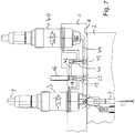
- a media valve 3 which is to be used as a multi-color media valve, with a circulation valve 40 is shown.
- the connection of the media valve 3 corresponds to that in the 1 to 4 is shown.
- the circulation valve 40 which in principle has the same structure as the media valve.
- the adjusting piston not shown here, is arranged such that pressurization via an additional control channel 42 leads to the valve closing - and not - as with the media valve, to the valve opening.
- media valve 3 and circulation valve 40 shown here serves to clarify the mode of operation.
- the media valves 3 and 3 are preferably used Circulation valves 40 in different circles - offset from one another - arranged.
- this also makes it necessary to provide two parallel switching valves (19, 41), namely one for the media valve 3 and an additional switching valve 41 for the circulation valve 40, as shown here. In terms of function, however, only one switching valve is required which opens or closes both control channels 18, 42.
- the media valve outlet of the circulation valve 40 has no opening in the front 6 of the stator 1, but rather is connected to the valve chamber of the media valve 3 via a connecting channel 44 within the stator 1.
- the additional control channel 42 to the circulation valve 40 can also be controlled by the switching valve 19 of the media valve 3, so that the additional switching valve 41 shown for the circulation valve 40 can be dispensed with.
- Fig. 8 shows the same situation as in Fig. 7 . However, here a control pressure is applied to the fluid connection 16, which causes the media valve 3 to open and the circulation valve 40 to close.
- a medium that rests on the media feed 4 of the media valve can, as in connection with the 1 to 4 described, via the open media valve 3 into the media line 7 and further to a consumption (spray gun). There is no return of the medium via the circulation valve 40, since this is closed.
- Fig. 9 shows the situation with a color change.
- the selection head 2 is removed from the stator 1 and can thus be rotated into a new position so that its media inlet 8 can be moved to the media valve outlet of another media valve.
- cams 22, 45 are also removed from the switching valves 19, 41, they are closed, so that regardless of a pressurization at the fluid connection 16, which may be necessary to open the other media valves, the media valve 3 shown is closed and the circulation valve 40 is open.
- a so-called sliding medium is first inserted into the media feed 4 of the media valve, which pushes the current color out of the media valve 3 and the circulation valve 40, and then, alternately, flushing medium and air are fed in around the media valve, the connecting channel 44 and the circulation valve from To remove paint residues. Then it is possible to apply a new paint color via the media feed 4 of the media valve 3.
- valve stem has a hollow channel 50 which ends in front of the valve closing body 24 and which has lateral exits 51.
- the head dips into a sleeve 52, in which the valve sealing seat 25 of the media valve 3 is formed and in the outer lateral surface of which a circumferential groove runs. Since the lateral surface rests on the wall of a media valve receiving bore in the stator 1, an annular channel 53 is created which is connected to the hollow channel 50 via a transverse bore 54 in the sleeve 52.
- the transverse bore 54 is located at the level of the lateral outputs 51 of the valve closing body 24 when the latter is in a closed position.
- the connecting channel 44 opens into the annular channel 53 opposite the transverse bore 54.
- the air or the flushing medium which emerges from the side outlets 51 is therefore forced to flow around the outside of the valve closing body 24 in order to reach the annular channel 53 via the transverse bore 54 and to flow from there in the direction of the connecting channel 44 can.
- This opposite arrangement of the connecting channel 44 and the transverse bore 54 ensures that the valve closing body 24 is cleaned on all sides.
Landscapes
- Multiple-Way Valves (AREA)
- Spray Control Apparatus (AREA)
Claims (9)
- Système de changement de couleur avec un stator (1) comportant une face avant, qui possède une pluralité de soupapes de fluide (3), dont les entrées sont reliées respectivement à une arrivée de fluide (4) et dont les sorties (5) débouchent dans la face avant du stator (1), sachant que chaque soupape de fluide (3) à l'intérieur d'une chambre de soupape constituée dans le stator comporte un corps de fermeture de soupape (24), qui peut être déplacé contre un siège étanche de soupape (25) orienté dans la chambre de soupape, sachant que le corps de fermeture de soupape est relié à un piston de réglage pouvant être sollicité par une pression de fluide et disposé à l'intérieur du stator, qui vient jouxter une chambre de pression de commande et avec une tête de sélection (2) disposée avant la face avant du stator (1), qui peut tourner autour d'un axe passant perpendiculairement à la face avant de stator et/ou parallèlement à la face avant de stator, sachant que la tête de sélection (2) comporte sur sa face arrière tournée vers la face avant de stator, une entrée de fluide (8), qui peut être placée par une rotation et/ou un déplacement de la tête de sélection (2) en superposition avec une des sorties de soupape de fluide (5) et sachant que la tête de sélection (2) comporte une conduite de fluide (7), qui relie l'entrée de fluide (8) à un point de prélèvement de fluide du système, sachant que dans la conduite de fluide (7) débouche une conduite de rinçage (11) dans laquelle se trouve une soupape antiretour de rinçage (12), qui s'ouvre en direction de la conduite de fluide (7), caractérisé en ce que dans l'entrée de fluide (8) est disposée en raccord direct à la face arrière de la tête de sélection (2), une soupape antiretour d'arrêt (10), qui bloque en direction de la face arrière de la tête de sélection (2) et en ce que la conduite de rinçage (11), dans laquelle se trouve la soupape antiretour de rinçage (12), débouche en aval de la soupape antiretour d'arrêt (10) dans la conduite de fluide (7).
- Système de changement de couleur selon la revendication 1, caractérisé en ce que le stator (1) comporte un raccord de fluide (16), qui est relié par respectivement un conduit de commande (18) aux chambres de pression de commande des soupapes de fluide (3) pour commander celles-ci, en ce qu'une soupape de commande (19) actionnable mécaniquement par une came est respectivement présente dans chacun de ces conduits de commande (18) et en ce qu'une came (22) est placée sur la face arrière de la tête de sélection (2), qui, lorsque la face arrière de la tête de sélection vient s'appliquer à la face avant du stator, ouvre la soupape de commande (19), qui appartient à la soupape de fluide (3), dont la sortie de soupape de fluide (5) dans le stator est reliée à l'entrée de fluide (8) dans la tête de sélection (2).
- Système de changement de couleur selon la revendication 2, caractérisé en ce que la tête de sélection (2) peut être déplacée perpendiculairement à la face avant de stator, en ce que la came (22) est constituée sur la face arrière de la tête de sélection (2) et fait saillie perpendiculairement de celle-ci, en ce que les soupapes de commande (19) sont placées dans des trous (23) débouchant sur la face avant du stator, sachant que la came (22) est adaptée pour plonger dans les trous et en ce que les trous sont orientés respectivement de la même manière vers les sorties de soupape de fluide (5) que la came (22) vers l'entrée de fluide (8).
- Système de changement de couleur selon la revendication 1, caractérisé en ce que le stator (1) possède pour chaque soupape de fluide (3) un raccord de fluide (32) sur sa face avant (6), qui est relié par un conduit de commande (31) à la chambre de pression de commande de la soupape de fluide (3) respective pour commander celle-ci, sachant que dans chaque conduit de commande (31) une soupape antiretour (33) est présente, qui bloque en direction du raccord de fluide (32) et en ce que dans la tête de sélection (2) passe un conduit de commande collecteur (34), qui débouche dans la face arrière de la tête de sélection (2), sachant que l'embouchure du conduit de commande collecteur (34) est alignée avec le raccord de fluide (32), dont le conduit de commande (31) mène à la soupape de fluide (3), dont la sortie de soupape de fluide (5) est en superposition avec l'entrée de fluide (8).
- Système de changement de couleur selon l'une quelconque des revendications précédentes, caractérisé en ce qu'au moins une soupape de circulation (40) dans le stator (1) est attribuée à une des soupapes de fluide (3), dont la sortie possède une liaison avec l'entrée de la soupape de fluide (3) et en ce que la soupape de fluide (3) est constituée de telle manière qu'elle est ouverte lors d'une sollicitation par pression de sa chambre de de pression de commande, en ce que le corps de fermeture de soupape de la soupape de circulation (40) est relié à un piston de réglage pouvant être sollicité par une pression de fluide et placé à l'intérieur du stator (1), qui jouxte une chambre de pression de commande, sachant que la soupape de circulation (40) est constituée de telle manière qu'elle est fermée lors d'une sollicitation par pression de sa chambre de pression de commande.
- Système de changement de couleur selon la revendication 5, caractérisé en ce que la chambre de pression de commande de la soupape de circulation (40) est reliée au raccord de fluide (16) par le biais d'un conduit de commande supplémentaire (42) pouvant être commandé.
- Système de changement de couleur selon la revendication 6, caractérisé en ce qu'une soupape de commande supplémentaire (41) se trouve dans le conduit de commande supplémentaire (42).
- Système de changement de couleur selon la revendication 7, caractérisé en ce qu'une soupape de commande supplémentaire (42) actionnable mécaniquement par une came (45) est présente dans le conduit de commande supplémentaire (41) et en ce qu'une came supplémentaire (45) est placée sur la face arrière de la tête de sélection (2), qui, lorsque la face arrière de la tête de sélection (2) est appliquée à la face avant du stator (1), ouvre la soupape de commande supplémentaire (41), qui appartient à la soupape de circulation (40).
- système de changement de couleur selon la revendication 5, caractérisé en ce que le stator (1) possède pour chaque soupape de fluide (3) un raccord de fluide (32) sur sa face avant (6), qui est relié par un conduit de commande (31) à la chambre de pression de commande de la soupape de fluide (3) respective pour commander celle-ci, sachant que dans chaque conduit de commande (31), une soupape antiretour (33) est présente qui bloque en direction du raccord de fluide (32) et en ce qu'un conduit de commande collecteur (34) passe dans la tête de sélection (2), qui débouche dans la face arrière de la tête de sélection (2), sachant que l'embouchure du conduit de commande collecteur (34) est alignée avec le raccord de fluide (32), dont le conduit de commande (31) mène à la soupape de fluide (3), dont la sortie de soupape de fluide (5) vient en superposition avec l'entrée de fluide (8) et en ce qu'au moins une des soupapes de fluide (3) dérive du conduit de commande (31) un conduit de commande supplémentaire (42) vers la soupape de circulation (40).
Priority Applications (1)
| Application Number | Priority Date | Filing Date | Title |
|---|---|---|---|
| EP19197160.5A EP3610955A1 (fr) | 2015-04-15 | 2016-04-15 | Système de changement de couleur |
Applications Claiming Priority (2)
| Application Number | Priority Date | Filing Date | Title |
|---|---|---|---|
| DE102015105774 | 2015-04-15 | ||
| PCT/DE2016/100181 WO2016165698A1 (fr) | 2015-04-15 | 2016-04-15 | Système de changement de couleur |
Related Child Applications (2)
| Application Number | Title | Priority Date | Filing Date |
|---|---|---|---|
| EP19197160.5A Division-Into EP3610955A1 (fr) | 2015-04-15 | 2016-04-15 | Système de changement de couleur |
| EP19197160.5A Division EP3610955A1 (fr) | 2015-04-15 | 2016-04-15 | Système de changement de couleur |
Publications (2)
| Publication Number | Publication Date |
|---|---|
| EP3283231A1 EP3283231A1 (fr) | 2018-02-21 |
| EP3283231B1 true EP3283231B1 (fr) | 2020-07-29 |
Family
ID=56117458
Family Applications (2)
| Application Number | Title | Priority Date | Filing Date |
|---|---|---|---|
| EP16728214.4A Not-in-force EP3283231B1 (fr) | 2015-04-15 | 2016-04-15 | Système de changement de couleur |
| EP19197160.5A Withdrawn EP3610955A1 (fr) | 2015-04-15 | 2016-04-15 | Système de changement de couleur |
Family Applications After (1)
| Application Number | Title | Priority Date | Filing Date |
|---|---|---|---|
| EP19197160.5A Withdrawn EP3610955A1 (fr) | 2015-04-15 | 2016-04-15 | Système de changement de couleur |
Country Status (3)
| Country | Link |
|---|---|
| EP (2) | EP3283231B1 (fr) |
| DE (2) | DE112016001728A5 (fr) |
| WO (1) | WO2016165698A1 (fr) |
Families Citing this family (1)
| Publication number | Priority date | Publication date | Assignee | Title |
|---|---|---|---|---|
| CN107694856B (zh) * | 2017-11-17 | 2023-05-23 | 常德烟草机械有限责任公司 | 一种自动对接系统 |
Family Cites Families (9)
| Publication number | Priority date | Publication date | Assignee | Title |
|---|---|---|---|---|
| US3240225A (en) * | 1963-01-17 | 1966-03-15 | Benjamin G Barrows | Selecting and purging apparatus |
| DE4339302C2 (de) * | 1993-11-18 | 1999-12-30 | Abb Patent Gmbh | Farbwechselblock mit Leckageindikatoren |
| FR2803776B1 (fr) * | 2000-01-14 | 2002-06-07 | Sames Sa | Installation de projection de produit de revetement |
| US6945483B2 (en) * | 2000-12-07 | 2005-09-20 | Fanuc Robotics North America, Inc. | Electrostatic painting apparatus with paint filling station and method for operating same |
| DE20122759U1 (de) | 2001-03-29 | 2007-08-23 | Dürr Systems GmbH | Farbwechselsystem für eine Beschichtungsanlage |
| ES2399882T3 (es) | 2007-12-28 | 2013-04-04 | Industra Industrieanlagen - Maschinen Und Teile Gmbh | Sistema cambiador de color de pintura y procedimiento para cambiar un color de pintura |
| JP5596950B2 (ja) * | 2009-09-23 | 2014-09-24 | ランズバーグ・インダストリー株式会社 | 静電塗装機用の塗料カートリッジ及びこれを含む静電塗装機 |
| DE102015102332A1 (de) | 2014-02-18 | 2015-08-20 | Apson Lackiertechnik Gmbh | Farbwechselsystem |
| EP2987558B1 (fr) * | 2014-08-19 | 2017-12-27 | ABB Schweiz AG | Changeur de couleur |
-
2016
- 2016-04-15 DE DE112016001728.6T patent/DE112016001728A5/de not_active Withdrawn
- 2016-04-15 EP EP16728214.4A patent/EP3283231B1/fr not_active Not-in-force
- 2016-04-15 WO PCT/DE2016/100181 patent/WO2016165698A1/fr not_active Ceased
- 2016-04-15 EP EP19197160.5A patent/EP3610955A1/fr not_active Withdrawn
- 2016-04-15 DE DE102016107042.4A patent/DE102016107042A1/de not_active Withdrawn
Non-Patent Citations (1)
| Title |
|---|
| None * |
Also Published As
| Publication number | Publication date |
|---|---|
| DE102016107042A1 (de) | 2016-10-20 |
| EP3610955A1 (fr) | 2020-02-19 |
| DE112016001728A5 (de) | 2018-01-04 |
| EP3283231A1 (fr) | 2018-02-21 |
| WO2016165698A1 (fr) | 2016-10-20 |
Similar Documents
| Publication | Publication Date | Title |
|---|---|---|
| EP0061630B1 (fr) | Pompe à engrenage à dispositif pour nettoyer | |
| DE2043789C3 (de) | Vorrichtung zum Farbspritzen einer Folge von Gegenständen | |
| DE1285819B (de) | Mehrfachsteuerventil | |
| EP2065100B1 (fr) | Dispositif de pulvérisation d'agent séparateur pour une machine de coulée | |
| CH623927A5 (fr) | ||
| EP3283231B1 (fr) | Système de changement de couleur | |
| DE1621857A1 (de) | Spritzpistole | |
| DE102007007645B3 (de) | Ventil mit Schaltstellungsverriegelung | |
| EP1991791B1 (fr) | Batterie de distributeurs à distributeur de sécurité | |
| EP2075073B1 (fr) | Système de changement de couleur et procédé de changement de couleur | |
| DE20305232U1 (de) | Ventilblock | |
| DE102015102332A1 (de) | Farbwechselsystem | |
| EP1250964B1 (fr) | Procédé et valve d'alimentation en liquide d'un élément désaccoupable d'une installation de revêtement | |
| EP1468745B1 (fr) | Elément de pulvérisation pour une tête de pulvérisation | |
| EP3033181B1 (fr) | Dispositif de changement de substances de revêtement et système de revêtement d'objets | |
| EP2554275B1 (fr) | Changeur de teinte | |
| DE19633191C2 (de) | Umschaltventil für ein Druckmedium | |
| EP1384518B1 (fr) | Procédé ainsi qu'ensemble de valves pour commander le changement de couleur dans une installation de revêtement | |
| DE102016113505A1 (de) | Farbwechselsystem | |
| DE3227656C2 (fr) | ||
| DE19641073A1 (de) | Druckmittelbetätigbares Ventil | |
| EP0496052B1 (fr) | Dispositif pour la pulvérisation de liant fluide spécialement le bitume | |
| DE102021214056B4 (de) | Wegeventil | |
| DE4214778C2 (de) | Sprühbeschichtungseinrichtung für flüssige Farbe | |
| EP2606981B1 (fr) | Module de changement de teinte et changeur de teinte |
Legal Events
| Date | Code | Title | Description |
|---|---|---|---|
| STAA | Information on the status of an ep patent application or granted ep patent |
Free format text: STATUS: THE INTERNATIONAL PUBLICATION HAS BEEN MADE |
|
| PUAI | Public reference made under article 153(3) epc to a published international application that has entered the european phase |
Free format text: ORIGINAL CODE: 0009012 |
|
| STAA | Information on the status of an ep patent application or granted ep patent |
Free format text: STATUS: REQUEST FOR EXAMINATION WAS MADE |
|
| 17P | Request for examination filed |
Effective date: 20171012 |
|
| AK | Designated contracting states |
Kind code of ref document: A1 Designated state(s): AL AT BE BG CH CY CZ DE DK EE ES FI FR GB GR HR HU IE IS IT LI LT LU LV MC MK MT NL NO PL PT RO RS SE SI SK SM TR |
|
| AX | Request for extension of the european patent |
Extension state: BA ME |
|
| DAV | Request for validation of the european patent (deleted) | ||
| DAX | Request for extension of the european patent (deleted) | ||
| RIC1 | Information provided on ipc code assigned before grant |
Ipc: B05B 12/14 20060101ALI20161025BHEP Ipc: B05B 15/02 20181130AFI20161025BHEP |
|
| RIC1 | Information provided on ipc code assigned before grant |
Ipc: B05B 15/02 20060101AFI20161025BHEP Ipc: B05B 12/14 20060101ALI20161025BHEP |
|
| STAA | Information on the status of an ep patent application or granted ep patent |
Free format text: STATUS: EXAMINATION IS IN PROGRESS |
|
| 17Q | First examination report despatched |
Effective date: 20190418 |
|
| REG | Reference to a national code |
Ref country code: DE Ref legal event code: R079 Ref document number: 502016010662 Country of ref document: DE Free format text: PREVIOUS MAIN CLASS: B05B0015020000 Ipc: B05B0012140000 |
|
| RIC1 | Information provided on ipc code assigned before grant |
Ipc: B08B 9/027 20060101ALI20191203BHEP Ipc: B05B 12/14 20060101AFI20191203BHEP Ipc: B05B 15/55 20180101ALI20191203BHEP |
|
| GRAP | Despatch of communication of intention to grant a patent |
Free format text: ORIGINAL CODE: EPIDOSNIGR1 |
|
| STAA | Information on the status of an ep patent application or granted ep patent |
Free format text: STATUS: GRANT OF PATENT IS INTENDED |
|
| GRAS | Grant fee paid |
Free format text: ORIGINAL CODE: EPIDOSNIGR3 |
|
| INTG | Intention to grant announced |
Effective date: 20200210 |
|
| GRAA | (expected) grant |
Free format text: ORIGINAL CODE: 0009210 |
|
| STAA | Information on the status of an ep patent application or granted ep patent |
Free format text: STATUS: THE PATENT HAS BEEN GRANTED |
|
| AK | Designated contracting states |
Kind code of ref document: B1 Designated state(s): AL AT BE BG CH CY CZ DE DK EE ES FI FR GB GR HR HU IE IS IT LI LT LU LV MC MK MT NL NO PL PT RO RS SE SI SK SM TR |
|
| REG | Reference to a national code |
Ref country code: CH Ref legal event code: EP |
|
| REG | Reference to a national code |
Ref country code: DE Ref legal event code: R096 Ref document number: 502016010662 Country of ref document: DE |
|
| REG | Reference to a national code |
Ref country code: AT Ref legal event code: REF Ref document number: 1295177 Country of ref document: AT Kind code of ref document: T Effective date: 20200815 |
|
| REG | Reference to a national code |
Ref country code: IE Ref legal event code: FG4D Free format text: LANGUAGE OF EP DOCUMENT: GERMAN |
|
| REG | Reference to a national code |
Ref country code: LT Ref legal event code: MG4D |
|
| REG | Reference to a national code |
Ref country code: NL Ref legal event code: MP Effective date: 20200729 |
|
| PG25 | Lapsed in a contracting state [announced via postgrant information from national office to epo] |
Ref country code: HR Free format text: LAPSE BECAUSE OF FAILURE TO SUBMIT A TRANSLATION OF THE DESCRIPTION OR TO PAY THE FEE WITHIN THE PRESCRIBED TIME-LIMIT Effective date: 20200729 Ref country code: LT Free format text: LAPSE BECAUSE OF FAILURE TO SUBMIT A TRANSLATION OF THE DESCRIPTION OR TO PAY THE FEE WITHIN THE PRESCRIBED TIME-LIMIT Effective date: 20200729 Ref country code: FI Free format text: LAPSE BECAUSE OF FAILURE TO SUBMIT A TRANSLATION OF THE DESCRIPTION OR TO PAY THE FEE WITHIN THE PRESCRIBED TIME-LIMIT Effective date: 20200729 Ref country code: PT Free format text: LAPSE BECAUSE OF FAILURE TO SUBMIT A TRANSLATION OF THE DESCRIPTION OR TO PAY THE FEE WITHIN THE PRESCRIBED TIME-LIMIT Effective date: 20201130 Ref country code: SE Free format text: LAPSE BECAUSE OF FAILURE TO SUBMIT A TRANSLATION OF THE DESCRIPTION OR TO PAY THE FEE WITHIN THE PRESCRIBED TIME-LIMIT Effective date: 20200729 Ref country code: ES Free format text: LAPSE BECAUSE OF FAILURE TO SUBMIT A TRANSLATION OF THE DESCRIPTION OR TO PAY THE FEE WITHIN THE PRESCRIBED TIME-LIMIT Effective date: 20200729 Ref country code: GR Free format text: LAPSE BECAUSE OF FAILURE TO SUBMIT A TRANSLATION OF THE DESCRIPTION OR TO PAY THE FEE WITHIN THE PRESCRIBED TIME-LIMIT Effective date: 20201030 Ref country code: NO Free format text: LAPSE BECAUSE OF FAILURE TO SUBMIT A TRANSLATION OF THE DESCRIPTION OR TO PAY THE FEE WITHIN THE PRESCRIBED TIME-LIMIT Effective date: 20201029 Ref country code: BG Free format text: LAPSE BECAUSE OF FAILURE TO SUBMIT A TRANSLATION OF THE DESCRIPTION OR TO PAY THE FEE WITHIN THE PRESCRIBED TIME-LIMIT Effective date: 20201029 |
|
| PG25 | Lapsed in a contracting state [announced via postgrant information from national office to epo] |
Ref country code: LV Free format text: LAPSE BECAUSE OF FAILURE TO SUBMIT A TRANSLATION OF THE DESCRIPTION OR TO PAY THE FEE WITHIN THE PRESCRIBED TIME-LIMIT Effective date: 20200729 Ref country code: RS Free format text: LAPSE BECAUSE OF FAILURE TO SUBMIT A TRANSLATION OF THE DESCRIPTION OR TO PAY THE FEE WITHIN THE PRESCRIBED TIME-LIMIT Effective date: 20200729 Ref country code: PL Free format text: LAPSE BECAUSE OF FAILURE TO SUBMIT A TRANSLATION OF THE DESCRIPTION OR TO PAY THE FEE WITHIN THE PRESCRIBED TIME-LIMIT Effective date: 20200729 Ref country code: IS Free format text: LAPSE BECAUSE OF FAILURE TO SUBMIT A TRANSLATION OF THE DESCRIPTION OR TO PAY THE FEE WITHIN THE PRESCRIBED TIME-LIMIT Effective date: 20201129 |
|
| PG25 | Lapsed in a contracting state [announced via postgrant information from national office to epo] |
Ref country code: NL Free format text: LAPSE BECAUSE OF FAILURE TO SUBMIT A TRANSLATION OF THE DESCRIPTION OR TO PAY THE FEE WITHIN THE PRESCRIBED TIME-LIMIT Effective date: 20200729 |
|
| PG25 | Lapsed in a contracting state [announced via postgrant information from national office to epo] |
Ref country code: IT Free format text: LAPSE BECAUSE OF FAILURE TO SUBMIT A TRANSLATION OF THE DESCRIPTION OR TO PAY THE FEE WITHIN THE PRESCRIBED TIME-LIMIT Effective date: 20200729 Ref country code: EE Free format text: LAPSE BECAUSE OF FAILURE TO SUBMIT A TRANSLATION OF THE DESCRIPTION OR TO PAY THE FEE WITHIN THE PRESCRIBED TIME-LIMIT Effective date: 20200729 Ref country code: CZ Free format text: LAPSE BECAUSE OF FAILURE TO SUBMIT A TRANSLATION OF THE DESCRIPTION OR TO PAY THE FEE WITHIN THE PRESCRIBED TIME-LIMIT Effective date: 20200729 Ref country code: DK Free format text: LAPSE BECAUSE OF FAILURE TO SUBMIT A TRANSLATION OF THE DESCRIPTION OR TO PAY THE FEE WITHIN THE PRESCRIBED TIME-LIMIT Effective date: 20200729 Ref country code: SM Free format text: LAPSE BECAUSE OF FAILURE TO SUBMIT A TRANSLATION OF THE DESCRIPTION OR TO PAY THE FEE WITHIN THE PRESCRIBED TIME-LIMIT Effective date: 20200729 Ref country code: RO Free format text: LAPSE BECAUSE OF FAILURE TO SUBMIT A TRANSLATION OF THE DESCRIPTION OR TO PAY THE FEE WITHIN THE PRESCRIBED TIME-LIMIT Effective date: 20200729 |
|
| REG | Reference to a national code |
Ref country code: DE Ref legal event code: R097 Ref document number: 502016010662 Country of ref document: DE |
|
| PG25 | Lapsed in a contracting state [announced via postgrant information from national office to epo] |
Ref country code: AL Free format text: LAPSE BECAUSE OF FAILURE TO SUBMIT A TRANSLATION OF THE DESCRIPTION OR TO PAY THE FEE WITHIN THE PRESCRIBED TIME-LIMIT Effective date: 20200729 |
|
| PLBE | No opposition filed within time limit |
Free format text: ORIGINAL CODE: 0009261 |
|
| STAA | Information on the status of an ep patent application or granted ep patent |
Free format text: STATUS: NO OPPOSITION FILED WITHIN TIME LIMIT |
|
| PG25 | Lapsed in a contracting state [announced via postgrant information from national office to epo] |
Ref country code: SK Free format text: LAPSE BECAUSE OF FAILURE TO SUBMIT A TRANSLATION OF THE DESCRIPTION OR TO PAY THE FEE WITHIN THE PRESCRIBED TIME-LIMIT Effective date: 20200729 |
|
| 26N | No opposition filed |
Effective date: 20210430 |
|
| PGFP | Annual fee paid to national office [announced via postgrant information from national office to epo] |
Ref country code: DE Payment date: 20210202 Year of fee payment: 6 Ref country code: FR Payment date: 20210423 Year of fee payment: 6 |
|
| PG25 | Lapsed in a contracting state [announced via postgrant information from national office to epo] |
Ref country code: SI Free format text: LAPSE BECAUSE OF FAILURE TO SUBMIT A TRANSLATION OF THE DESCRIPTION OR TO PAY THE FEE WITHIN THE PRESCRIBED TIME-LIMIT Effective date: 20200729 |
|
| PG25 | Lapsed in a contracting state [announced via postgrant information from national office to epo] |
Ref country code: MC Free format text: LAPSE BECAUSE OF FAILURE TO SUBMIT A TRANSLATION OF THE DESCRIPTION OR TO PAY THE FEE WITHIN THE PRESCRIBED TIME-LIMIT Effective date: 20200729 |
|
| GBPC | Gb: european patent ceased through non-payment of renewal fee |
Effective date: 20210415 |
|
| PG25 | Lapsed in a contracting state [announced via postgrant information from national office to epo] |
Ref country code: LU Free format text: LAPSE BECAUSE OF NON-PAYMENT OF DUE FEES Effective date: 20210415 |
|
| REG | Reference to a national code |
Ref country code: BE Ref legal event code: MM Effective date: 20210430 |
|
| PG25 | Lapsed in a contracting state [announced via postgrant information from national office to epo] |
Ref country code: GB Free format text: LAPSE BECAUSE OF NON-PAYMENT OF DUE FEES Effective date: 20210415 Ref country code: CH Free format text: LAPSE BECAUSE OF NON-PAYMENT OF DUE FEES Effective date: 20210430 Ref country code: LI Free format text: LAPSE BECAUSE OF NON-PAYMENT OF DUE FEES Effective date: 20210430 |
|
| PG25 | Lapsed in a contracting state [announced via postgrant information from national office to epo] |
Ref country code: IE Free format text: LAPSE BECAUSE OF NON-PAYMENT OF DUE FEES Effective date: 20210415 |
|
| PG25 | Lapsed in a contracting state [announced via postgrant information from national office to epo] |
Ref country code: IS Free format text: LAPSE BECAUSE OF FAILURE TO SUBMIT A TRANSLATION OF THE DESCRIPTION OR TO PAY THE FEE WITHIN THE PRESCRIBED TIME-LIMIT Effective date: 20201129 |
|
| REG | Reference to a national code |
Ref country code: AT Ref legal event code: MM01 Ref document number: 1295177 Country of ref document: AT Kind code of ref document: T Effective date: 20210415 |
|
| PG25 | Lapsed in a contracting state [announced via postgrant information from national office to epo] |
Ref country code: BE Free format text: LAPSE BECAUSE OF NON-PAYMENT OF DUE FEES Effective date: 20210430 |
|
| PG25 | Lapsed in a contracting state [announced via postgrant information from national office to epo] |
Ref country code: AT Free format text: LAPSE BECAUSE OF NON-PAYMENT OF DUE FEES Effective date: 20210415 |
|
| REG | Reference to a national code |
Ref country code: DE Ref legal event code: R119 Ref document number: 502016010662 Country of ref document: DE |
|
| PG25 | Lapsed in a contracting state [announced via postgrant information from national office to epo] |
Ref country code: FR Free format text: LAPSE BECAUSE OF NON-PAYMENT OF DUE FEES Effective date: 20220430 Ref country code: DE Free format text: LAPSE BECAUSE OF NON-PAYMENT OF DUE FEES Effective date: 20221103 |
|
| PG25 | Lapsed in a contracting state [announced via postgrant information from national office to epo] |
Ref country code: HU Free format text: LAPSE BECAUSE OF FAILURE TO SUBMIT A TRANSLATION OF THE DESCRIPTION OR TO PAY THE FEE WITHIN THE PRESCRIBED TIME-LIMIT; INVALID AB INITIO Effective date: 20160415 |
|
| PG25 | Lapsed in a contracting state [announced via postgrant information from national office to epo] |
Ref country code: CY Free format text: LAPSE BECAUSE OF FAILURE TO SUBMIT A TRANSLATION OF THE DESCRIPTION OR TO PAY THE FEE WITHIN THE PRESCRIBED TIME-LIMIT Effective date: 20200729 |
|
| PG25 | Lapsed in a contracting state [announced via postgrant information from national office to epo] |
Ref country code: MK Free format text: LAPSE BECAUSE OF FAILURE TO SUBMIT A TRANSLATION OF THE DESCRIPTION OR TO PAY THE FEE WITHIN THE PRESCRIBED TIME-LIMIT Effective date: 20200729 |
|
| PG25 | Lapsed in a contracting state [announced via postgrant information from national office to epo] |
Ref country code: MT Free format text: LAPSE BECAUSE OF FAILURE TO SUBMIT A TRANSLATION OF THE DESCRIPTION OR TO PAY THE FEE WITHIN THE PRESCRIBED TIME-LIMIT Effective date: 20200729 |
|
| PG25 | Lapsed in a contracting state [announced via postgrant information from national office to epo] |
Ref country code: TR Free format text: LAPSE BECAUSE OF FAILURE TO SUBMIT A TRANSLATION OF THE DESCRIPTION OR TO PAY THE FEE WITHIN THE PRESCRIBED TIME-LIMIT Effective date: 20200729 |