EP3283260B1 - Sortimentbox und anordnung mit wenigstens einer sortimentbox und einer halteleiste - Google Patents
Sortimentbox und anordnung mit wenigstens einer sortimentbox und einer halteleiste Download PDFInfo
- Publication number
- EP3283260B1 EP3283260B1 EP16711570.8A EP16711570A EP3283260B1 EP 3283260 B1 EP3283260 B1 EP 3283260B1 EP 16711570 A EP16711570 A EP 16711570A EP 3283260 B1 EP3283260 B1 EP 3283260B1
- Authority
- EP
- European Patent Office
- Prior art keywords
- assortment box
- holding device
- assortment
- groove
- holding
- Prior art date
- Legal status (The legal status is an assumption and is not a legal conclusion. Google has not performed a legal analysis and makes no representation as to the accuracy of the status listed.)
- Active
Links
Images



Classifications
-
- B—PERFORMING OPERATIONS; TRANSPORTING
- B25—HAND TOOLS; PORTABLE POWER-DRIVEN TOOLS; MANIPULATORS
- B25H—WORKSHOP EQUIPMENT, e.g. FOR MARKING-OUT WORK; STORAGE MEANS FOR WORKSHOPS
- B25H3/00—Storage means or arrangements for workshops facilitating access to, or handling of, work tools or instruments
- B25H3/02—Boxes
- B25H3/021—Boxes comprising a number of connected storage elements
- B25H3/022—Boxes comprising a number of connected storage elements in fixed relationship
-
- B—PERFORMING OPERATIONS; TRANSPORTING
- B25—HAND TOOLS; PORTABLE POWER-DRIVEN TOOLS; MANIPULATORS
- B25H—WORKSHOP EQUIPMENT, e.g. FOR MARKING-OUT WORK; STORAGE MEANS FOR WORKSHOPS
- B25H3/00—Storage means or arrangements for workshops facilitating access to, or handling of, work tools or instruments
- B25H3/04—Racks
Definitions
- the invention relates to an assortment box for accommodating small parts with a base and four side walls, the assortment box having shape features for non-slip arrangement in transport and storage units, in particular suitcases, shelves, workshop trolleys.
- the invention also relates to an arrangement with at least one assortment box according to the invention and a retaining strip. Some examples are from DE202014101910U1 or US2702649A known.
- an assortment box is to be improved in terms of its flexible usability.
- an assortment box with the features of claim 1 is provided for this purpose.
- an assortment box for accommodating small parts with a base and four side walls
- the assortment box having shape features for non-slip arrangement in transport and storage units, in particular suitcases, shelves, workshop trolleys, with a holding device for the tool-free attachment of the assortment box to a retaining strip, with the holding device being designed as a hook-shaped projection that extends from the top of the side wall, with an inside of at least one of the side walls in its upper section adjoining an opening of the assortment box having an angle of more than 90° and less than 110°, in particular 100°, with the base and that the side wall has a lower section arranged perpendicularly to the base, to which, in the upward direction, towards the opening of the assortment box, the section arranged obliquely to the base adjoins reads
- the assortment box according to the invention can not only be arranged in a transport and storage unit, but it can also be attached to a holding strip.
- Known assortment boxes can, for example, be removed from a transport box and then placed on a workbench. There, however, the assortment boxes are often in the way, since the workbench is actually needed for storing and processing a workpiece.
- the assortment box according to the invention can be hung in a retaining bar.
- the retaining bar can be attached to a wall behind a workbench. A worker can then remove the assortment box from the transport and storage unit and hang it in the retaining bar.
- the workbench itself remains free for the workpiece to be processed and the assortment box can be attached to the holding rail at an ideal grip height.
- a retaining strip for example, it is also possible to attach a retaining strip to a workshop trolley.
- the worker can then remove a required assortment box, for example with the screws that are currently required, from the workshop trolley and hang it in the retaining bar on one side of the workshop trolley.
- the assortment box is therefore very easily accessible and safely arranged.
- the assortment box does not take up the already scarce space on the workshop trolley
- the assortment box can be hung in a holding strip in a simple manner by means of a hook-shaped holding device.
- the holding device is arranged in the area of the upper edge of at least one of the side walls, which delimits the opening of the assortment box in sections.
- the assortment box can be securely attached to the holding device, since the center of gravity of the assortment box is then below the holding device.
- the holding device extends over the entire width of one of the side walls.
- the assortment box can be hung in the holding strip in a very simple manner, even if the worker cannot see the holding device himself. Because he can then create the assortment box with the side wall on the retaining bar and then move the assortment box relative to the retaining bar down until the hook-shaped projection engages in the retaining bar.
- the outside of the side wall with the holding device is designed to be smooth and without projections.
- the inside of at least one of the side walls forms an angle of more than 90° and less than 110° with the floor, not only is it easy to reach into the assortment box, for example to get small parts, but also at the diagonal to the Floor arranged section of the side wall can be arranged, for example, a label or a label. Since the inscription or the label is then already inclined towards an observer, its legibility is considerably improved.
- the side wall with the holding device is preferably beveled on its inside, ie in its upper area it encloses an angle of more than 90° and less than 110° with the floor.
- the improved legibility of a label or an inscription on the beveled section of the side wall is both when the assortment box is arranged in a case, especially when looking at the assortment box from above, and when the assortment box is arranged on a retaining strip, especially when the assortment box is viewed from an approximately horizontal direction , given.
- the shape features are designed as projections starting from an underside of a base facing away from the interior of the assortment box.
- Such projections on the bottom of the assortment box can be used to securely lock the assortment box in a transport and storage facility.
- the inside of the bottom facing the interior of the assortment box is advantageously smooth in order to enable easy removal of small parts.
- two opposite inner sides facing an interior of the assortment box each have a groove for inserting a divider plate.
- a divider plate can be securely anchored, for example when very small parts are to be stored that would only insufficiently fill the full assortment box.
- no projections or guides on the side wall interfere with the removal of small parts from the assortment box if there is no divider plate.
- the grooves and the side edges of the divider plate have a dovetail-like cross section.
- a groove running parallel to the upper edge is provided on the upper edge of at least one of the side walls, the groove being provided for fastening a lid to the assortment box.
- a retaining strip of a lid can be clipped or pressed into the groove in order to anchor a pivotable lid to the assortment box in a particularly simple manner.
- the cover plate itself can then be attached to the retaining strip, for example by means of a film hinge.
- the groove for attaching a lid is advantageously open at the top, like the opening in the interior of the assortment box.
- the groove is provided on the upper edge of that side wall with the holding device.
- the holding device requires space at the upper edge of at least one of the side walls.
- the location of the groove for attaching a lid can then be accommodated in this area without taking up additional space.
- the groove advantageously forms a section of the holding device.
- the problem on which the invention is based is also solved by an arrangement according to claim 10 with at least one assortment box according to the invention and at least one holding strip, in which the holding strip has a first holding device matching the holding device of the assortment box.
- the holding strip has a second holding device that matches the holding device of the assortment box, the assortment box and the holding strip being arranged at a first angle to one another when the holding device of the assortment box engages in the first holding device and when the holding device of the assortment box engages in the second holding device are arranged at a second angle to one another which is different from the first angle.
- the assortment box can be arranged in two different positions or angular orientations on the retaining bar.
- the arrangement of the assortment box on the retaining bar can be adjusted to a current work situation or a worker's size. For example, if the worker kneels in front of a workpiece lying on the floor, he will arrange the assortment box on the retaining bar on a workshop trolley in such a way that he can easily reach into the assortment box from a lower position. On the other hand, if the worker processes a workpiece on the upper side of the workshop trolley, he becomes the assortment box hang it in the retaining bar so that it has optimal access to the assortment box when standing.
- two retaining strips can be arranged on the workshop trolley.
- the first holding device is designed as a first groove that runs through the longitudinal direction of the holding strip.
- a holding device on the holding strip as a groove can be accomplished in a simple and elegant manner.
- a suitably designed holding device on the assortment box can also be hung in a groove in a simple manner and yet securely fastened in the groove.
- the second holding device is designed as a continuous second groove in the longitudinal direction of the holding strip, the second groove being arranged at an angle of more than 0° to the first groove when viewed in cross section of the holding strip.
- the two grooves are thus arranged at a different angle to a rear side of the retaining strip, so that it can be ensured in a very simple manner that the assortment box is at a different angle depending on whether it is hung in the first groove or the second groove is arranged to the retaining strip. Seen in cross section, the grooves are therefore not parallel to one another.
- the grooves can be of different widths transversely to the longitudinal direction in order to be able to hang the assortment box at different angles.
- the holding strip is designed as an extruded profile or extruded profile
- Extruded profiles or extruded profiles can be produced inexpensively with very precise dimensions, for example as an aluminum extruded profile.
- the representation of 1 shows an assortment box 10 according to the invention, which is arranged in the lower part 12 of a transport case.
- the bottom of the transport case is provided with projections 14 arranged in a grid-like manner, into which projections on the underside of the bottom of the assortment box 10 engage.
- These protrusions on the underside of the bottom of the Assortment Box 10 are in 4 to recognize.
- the assortment box 10 can be arranged in different positions on the bottom of the transport case and the interaction of the projections on the underside of the bottom of the assortment box 10 with the projections 14 then ensures that the assortment box 10 cannot slide back and forth on the bottom of the transport case .
- a total of eight assortment boxes 10 can be arranged.
- the assortment boxes 10 can, for example, also be produced in different sizes, for example narrower, wider, shorter or longer than the assortment box 10 shown, so that small parts of the most varied sizes can be arranged in such assortment boxes.
- the lower part 12 of the transport case is only shown as an example, corresponding projections 14 can also be arranged, for example, on the shelves of shelves, on the drawer bottoms of workshop trolleys or the like in order to arrange assortment boxes 10 in a non-slip manner.
- the divider plate 16 extends from a bottom of the assortment box 10 to a height slightly below the upper edge of the assortment box 10.
- a hook-shaped holding device 18 can be seen on the assortment box 10.
- This hook-shaped holding device 18 extends from an in 1 top right side wall of assortment box 10.
- the holding device 18 is used to be able to hang the assortment box 10 in a holding bar, as shown in 6 is shown.
- An upper section 20 of the 1 The side wall of the assortment box 10 arranged at the top right is arranged at an angle to the bottom of the assortment box. This section 20 is provided for receiving an inscription, which can thus be easily recognized by a viewer who looks into the assortment box from an angle from above.
- the inclined section 20 also makes it easier to reach into the interior of the assortment box 10.
- the representation of 2 12 shows the assortment box 10 with the divider plate 16 pulled out.
- the divider plate 16 is inserted into grooves 22 which are arranged in opposite side walls of the assortment box 10.
- the grooves 22 each have a dovetail-like cross-section and the divider plate 16 has matching dovetail-like projections 24 on both of its side edges.
- the divider plate 16 runs flat at the side edges.
- the two lower corners 26 of the divider plate 16 are angularly recessed. This is because the grooves 22 end a little above a floor 28 of the assortment box 10 .
- the divider plate 16 can be placed on the bottom 28 of the assortment box 10 with its lower edge. However, the floor 28 itself is smooth and without a groove for the divider plate. If no divider plate 16 is arranged in the assortment box 10, a smooth floor is thereby available and small parts stored in the assortment box 10 cannot snag or get caught on the floor.
- Projections 30 can already be seen in sections on the underside of the base 28 facing away from the interior. These projections 30 serve, as already explained, to engage in projections or recesses 14 on the base of the lower part 12 of the transport case.
- the section 20 arranged obliquely to the floor 28 is also the in 2 and 1
- the side wall 36 of the assortment box 10 arranged at the top right can be seen.
- a section 32 of the side wall 36 arranged perpendicularly to the base 28 adjoins the section 20 arranged at an angle.
- the side wall 36 is thus tilted away from the floor 28 only in its upper region.
- the hook-shaped holding device 18 is in 2 recognizable in sections on the rear side of the side wall 36 of the assortment box 10 facing away from the viewer. As stated, the assortment box 10 is hung with this hook-shaped holding device 18 in a groove of a holding strip, as shown in 6 is shown. With the hook-shaped holding device 18, however, the assortment box 10 can also be hung, for example, in the peripheral edge of a workshop trolley. Tool trolleys usually have a raised edge made of comparatively thin sheet metal, which is intended to prevent small parts from rolling off the top of the tool trolley. The assortment box 10 with the hook-shaped holding device 18 can also be hung in such a peripheral edge.
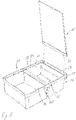
- the representation of 3 shows a view of the assortment box 10 obliquely from above. Additionally is in 3 a hinged lid 50 which can be attached to the assortment box 10 is shown schematically.
- the hinged lid 50 is provided with a holding strip 52 which can be clipped into a groove 54 which is arranged at the upper end of the side wall 36 of the assortment box 10 .
- the groove 54 is part of the hook-shaped projection 34.
- the retaining strip 52 is pressed into the groove 54 from above.
- the retaining strip 52 and the groove 54 are dimensioned in such a way that simply pressing in is sufficient to anchor the hinged lid 50 to the assortment box 10 .
- the interior of the assortment box 10 is provided with a circumferential shoulder 56 at its upper end. Above the step 56, the interior expands slightly outwards, so that an upper peripheral edge 58 of the assortment box 10 is offset slightly outwards compared to the sections of the side walls ending on the bottom 28.
- This shoulder 56 serves to serve as an abutment for the hinged cover 50 in the closed state.
- the retaining strip 52 and the cover plate of the hinged cover 50 can be connected to one another by means of a conventional hinge, but also, for example, by means of a film hinge.
- An upper edge of the divider plate 16 is provided with a widened support 62 which is arranged at the height of the shoulder 56 when the divider plate 16 is fully inserted.
- the cover plate of the hinged cover 50 can thus also rest on the widened upper side 62 of the divider plate 16, which reliably prevents small parts from migrating or moving from one half of the box to the other half of the box when the cover is closed.
- the representation of 4 shows the assortment box 10 from below. This view shows the projections 30 on the underside of the bottom of the assortment box 10, which, as has been explained, are matched to the projections 14 on the bottom of the lower part 12 of a transport case or other transport and storage unit.
- the hook-shaped holding device 18 is arranged in 4 the two sections 20, 32 of the side wall 36 in 4 below.
- the hook-shaped holding device 18 is designed as a hook-shaped projection 34 which extends from the top of the side wall 36 of the assortment box 10 .
- the top of sidewall 36, which includes sections 32 and 20, is in 4 arranged below, since the assortment box is shown with its opening downwards.
- figure 5 shows a sectional view of the assortment box 10 according to the invention.
- the hook-shaped projection 34 extends from an upper side of the figure 5 right side wall 36 from.
- the side wall 36 has a lower section 32 which is arranged perpendicularly to the base 28 and which is adjoined in the upward direction towards the opening of the assortment box 10 by the section 20 arranged obliquely to the base 28 .
- Section 20 encloses an angle of more than 90° and less than 110°, in particular 100°, with base 28 .
- the inclined section 20 makes it easier to reach into the interior of the assortment box. For a viewer who figure 5 would look into the assortment box 10 diagonally from the top left, an inscription on the section 20 is very easy to read.
- the assortment box 10 In order to hang the assortment box 10 in a groove of a holding bar or on a projection, the assortment box 10 only has to be placed with the outside of the side wall 36 in the area of section 32 against the holding bar or the projection. The assortment box 10 can then simply be moved downwards until the projection or retaining strip engages in the space between the hook-shaped projection 34 and the section 20 of the side wall 36 . If the assortment box 10 is then released, it is securely fastened by means of the hook-shaped projection 34 .
- the hook-shaped projection 34 has a slight undercut 38.
- This undercut can contribute to attaching the assortment box 10 particularly securely to a holding strip or a projection.
- the assortment box 10 can easily be hung in a projection or a holding bar without the hook-shaped projection 34 being visible to an observer. This makes the Assortment Box 10 extremely user-friendly.
- the representation of 6 shows a retaining strip 40 as can be used together with the assortment box 10 according to the invention.
- the retaining strip 40 is designed as an extruded aluminum profile and has a number of screw holes 42 with which it can be attached to a wall or to a workshop trolley or to another suitable location.
- the holding bar 40 is provided with a first groove 44 and a second groove 46 .
- the two grooves 44, 46 do not run parallel to one another as seen in the cross section of the retaining strip and therefore close with an in 6 not recognizable back 48 of the retaining bar 40 a different angle. Seen in cross section, the grooves 44, 46 are arranged at an angle of more than 0° to one another.
- the groove 44 is wider transversely to the longitudinal direction than the groove 46.
- the groove 46 takes up the section of the hook-shaped projection 34 that figure 5 is arranged below the undercut 38, essentially without play.
- the groove 44 is significantly wider.
- the side walls of the groove 44 are arranged parallel to a rear side 48 of the holding strip 40 .
- the side walls of the groove 46 are arranged obliquely to the rear side 48 .
- the two grooves 44, 46 are each provided for hanging the hook-shaped projection 34 of the assortment box 10.
- the assortment box 10 will hang approximately perpendicularly to the rear side 48 of the retaining strip 40 when it is hung in the groove 44 .
- the assortment box 10 will then also hang approximately perpendicularly to a wall on which the retaining strip 40 is attached.
- the assortment box 10 will hang slightly obliquely to the rear side 48 of the retaining bar 40 and thus also obliquely to a wall to which the retaining bar 40 is attached. The assortment box will then hang slightly tilted downwards according to the arrangement of the groove 46 . Reaching into the interior of the assortment box 10 to remove small parts is then made much easier, particularly when a worker wants to reach into the assortment box 10 from a lower position, for example a kneeling position.
Landscapes
- Engineering & Computer Science (AREA)
- Mechanical Engineering (AREA)
- Details Of Rigid Or Semi-Rigid Containers (AREA)
- Cartons (AREA)
- Warehouses Or Storage Devices (AREA)
- Housing For Livestock And Birds (AREA)
Applications Claiming Priority (2)
| Application Number | Priority Date | Filing Date | Title |
|---|---|---|---|
| DE102015206606.1A DE102015206606A1 (de) | 2015-04-14 | 2015-04-14 | Sortimentbox und Anordnung mit wenigstens einer Sortimentbox und einer Halteleiste |
| PCT/EP2016/055709 WO2016165901A1 (de) | 2015-04-14 | 2016-03-16 | Sortimentbox und anordnung mit wenigstens einer sortimentbox und einer halteleiste |
Publications (2)
| Publication Number | Publication Date |
|---|---|
| EP3283260A1 EP3283260A1 (de) | 2018-02-21 |
| EP3283260B1 true EP3283260B1 (de) | 2022-06-15 |
Family
ID=55589819
Family Applications (1)
| Application Number | Title | Priority Date | Filing Date |
|---|---|---|---|
| EP16711570.8A Active EP3283260B1 (de) | 2015-04-14 | 2016-03-16 | Sortimentbox und anordnung mit wenigstens einer sortimentbox und einer halteleiste |
Country Status (9)
| Country | Link |
|---|---|
| EP (1) | EP3283260B1 (da) |
| CN (1) | CN107889476B (da) |
| AU (1) | AU2016249627B2 (da) |
| DE (1) | DE102015206606A1 (da) |
| DK (1) | DK3283260T3 (da) |
| ES (1) | ES2922808T3 (da) |
| PL (1) | PL3283260T3 (da) |
| PT (1) | PT3283260T (da) |
| WO (1) | WO2016165901A1 (da) |
Families Citing this family (9)
| Publication number | Priority date | Publication date | Assignee | Title |
|---|---|---|---|---|
| DE102015118024A1 (de) | 2015-10-22 | 2017-04-27 | Adolf Würth GmbH & Co. KG | Wandhalterung für stapelbaren Koffer mit multifunktionaler Befestigungsstruktur |
| NO343763B1 (en) * | 2017-07-13 | 2019-06-03 | Hung Tai Packing Design Co Ltd | Toolbox |
| CN112469618B (zh) * | 2018-06-01 | 2023-11-07 | 塔诺斯包装整理展示有限责任公司 | 运输设备 |
| CN109178635B (zh) * | 2018-08-17 | 2020-09-11 | 中车青岛四方机车车辆股份有限公司 | 一种小型零部件的通用储运装置 |
| DE102018007090A1 (de) | 2018-09-07 | 2020-03-12 | Adolf Würth Gmbh & Co Kg | Werkstattwagen |
| US20200095057A1 (en) * | 2018-09-24 | 2020-03-26 | Brian Conicella | Visually Distinctive Tarpaulins And Kits Thereof |
| CN110789829A (zh) * | 2019-11-06 | 2020-02-14 | 西安医学院 | 一种带有标记分类功能的流式抗体储存盒 |
| DE102020103322A1 (de) * | 2020-02-10 | 2021-08-12 | Adolf Würth Gmbh & Co Kg | Werkzeugverwaltungsvorrichtung mit Kulissenführung sowie Zapfen an Gelenkverbindung |
| US11884456B2 (en) | 2020-09-25 | 2024-01-30 | Techtronic Cordless Gp | Tool storage system |
Family Cites Families (22)
| Publication number | Priority date | Publication date | Assignee | Title |
|---|---|---|---|---|
| US2702649A (en) * | 1951-07-13 | 1955-02-22 | Allan K Neilson | Adjustable container for service parts |
| US4126366A (en) * | 1977-03-04 | 1978-11-21 | Hirsh Company | Rotatable, multiple storage bin assembly |
| DE8502042U1 (de) * | 1985-01-26 | 1988-05-11 | Kretzschmar, Günter, 7444 Beuren | Werkzeugkasten |
| DE8634432U1 (de) * | 1986-12-23 | 1987-02-12 | Adolf Würth GmbH & Co KG, 7118 Künzelsau | Einsatz für Sortimentskästen |
| DE3823142A1 (de) * | 1988-07-08 | 1990-01-11 | Bosch Gmbh Robert | Einrichtung zum griffgerechten bereitstellen von montageteilen |
| US20020074332A1 (en) * | 2000-12-18 | 2002-06-20 | Sami Sagol | Twin organizer pack |
| DE20216908U1 (de) * | 2002-11-02 | 2003-02-13 | TTS Tooltechnic Systems AG & Co. KG, 73240 Wendlingen | Behälter zur Aufnahme von Kleinteilen |
| US7165695B2 (en) * | 2003-02-11 | 2007-01-23 | Primesource Building Products, Inc. | Dispensing container for dispensing fasteners |
| DE20314773U1 (de) * | 2003-09-22 | 2003-12-04 | Elabo Gmbh | Leiste zum Anbringen von Lagerelementen |
| FR2866291B1 (fr) * | 2004-02-17 | 2006-04-14 | Macc | Ensemble de rangement pour vehicules utilitaires compose d'un nombre evolutif de racks et de mallettes |
| CN2863679Y (zh) * | 2006-01-06 | 2007-01-31 | 精中(宁波)五金实业有限公司 | 塑料挂盒 |
| US8136775B2 (en) * | 2009-06-30 | 2012-03-20 | Vance Chiang | Rack assembly |
| CN201693545U (zh) * | 2010-06-30 | 2011-01-05 | 贵阳永青仪电科技有限公司 | 仪表元器件存放装置 |
| CN201726703U (zh) * | 2010-07-07 | 2011-02-02 | 南京绿色组合环保有限公司 | 一种阳台绿化组合 |
| CN202080530U (zh) * | 2011-04-12 | 2011-12-21 | 徐兵 | 一种食物保鲜盒 |
| US8505728B2 (en) * | 2011-09-01 | 2013-08-13 | Chung-Hsiu Su | Portable tool storing device |
| AT512009B1 (de) * | 2011-10-13 | 2014-04-15 | Metzler Gmbh & Co Kg | Einrichtung zum lagern von utensilien, insbesondere werkzeug |
| CN202321033U (zh) * | 2011-12-02 | 2012-07-11 | 李群星 | 一种带挂钩的物品盒 |
| DE202013002265U1 (de) * | 2013-03-04 | 2013-06-13 | Minitec Maschinenbau Gmbh | Behälter zur Aufnahme von Kleinteilen |
| TWM478591U (zh) * | 2014-01-14 | 2014-05-21 | Hung Tai Packing Design Co Ltd | 工具箱結構 |
| DE202014101910U1 (de) * | 2014-04-08 | 2014-05-06 | Bott Gmbh & Co Kg | Behälter für Kleinteile |
| DE202014105326U1 (de) * | 2014-11-05 | 2014-11-26 | Ktl International Co., Ltd. | Werkzeugkasten und den besagten Werkzeugkasten beinhaltenden Werkzeugwagen |
-
2015
- 2015-04-14 DE DE102015206606.1A patent/DE102015206606A1/de not_active Withdrawn
-
2016
- 2016-03-16 AU AU2016249627A patent/AU2016249627B2/en active Active
- 2016-03-16 CN CN201680021423.9A patent/CN107889476B/zh active Active
- 2016-03-16 WO PCT/EP2016/055709 patent/WO2016165901A1/de not_active Ceased
- 2016-03-16 EP EP16711570.8A patent/EP3283260B1/de active Active
- 2016-03-16 PT PT167115708T patent/PT3283260T/pt unknown
- 2016-03-16 DK DK16711570.8T patent/DK3283260T3/da active
- 2016-03-16 PL PL16711570.8T patent/PL3283260T3/pl unknown
- 2016-03-16 ES ES16711570T patent/ES2922808T3/es active Active
Also Published As
| Publication number | Publication date |
|---|---|
| PT3283260T (pt) | 2022-08-02 |
| PL3283260T3 (pl) | 2022-10-17 |
| ES2922808T3 (es) | 2022-09-20 |
| WO2016165901A1 (de) | 2016-10-20 |
| EP3283260A1 (de) | 2018-02-21 |
| DK3283260T3 (da) | 2022-08-01 |
| AU2016249627A1 (en) | 2017-10-19 |
| AU2016249627B2 (en) | 2019-02-14 |
| DE102015206606A1 (de) | 2016-10-20 |
| CN107889476B (zh) | 2021-05-18 |
| CN107889476A (zh) | 2018-04-06 |
Similar Documents
| Publication | Publication Date | Title |
|---|---|---|
| EP3283260B1 (de) | Sortimentbox und anordnung mit wenigstens einer sortimentbox und einer halteleiste | |
| EP2428333B1 (de) | Werkzeugaufnahme | |
| DE102018116210A1 (de) | Ablageboden für ein Möbel oder Haushaltsgerät und Verfahren zur Montage eines Ablagebodens | |
| DE202012012595U1 (de) | Einrichtung zum Lagern von Utensilien | |
| WO2010121585A1 (de) | Aufbewahrungssystem für einen laderaum eines kraftfahrzeugs | |
| DE102013200336B4 (de) | Modulares System mit Rahmenmodul für einen Schrank oder eine Schublade | |
| EP1528878B1 (de) | Aufbewahrungsanordnung | |
| EP0043540B1 (de) | Sortimentskastenregal | |
| DE10259397B4 (de) | Regal für Warenlagerung und Darbietung in Einzelhandelsgeschäften | |
| DE102013206712A1 (de) | Haushaltskältegerät mit einem Transportsicherungskörper | |
| EP2454542B1 (de) | Kühlgutträger für ein kältegerät | |
| DE102010001451A1 (de) | Flaschenablage für ein Kältegerät | |
| WO2019092079A1 (de) | Reinigungsfahrwagen und verfahren zu dessen montage | |
| EP3072415B1 (de) | Möbelbeschlag zur ausbildung einer ausziehbaren abfallsammelvorrichtung und schrank mit einem solchen möbelbeschlag | |
| EP3000360B1 (de) | Objektaufbewahrungssystem | |
| EP2939565B1 (de) | In einem schrank aufgenommener auszug | |
| DE102013204938B4 (de) | Systemmöbel | |
| DE2258249C3 (de) | Kassettenregistratur | |
| WO2018028844A1 (de) | Profilbauteil und möbelsystem mit einem solchen profilbauteil | |
| EP3090655A1 (de) | Schubladencontainersystem für büromöbel | |
| DE102007058354A1 (de) | Systemmöbel | |
| DE102014202941A1 (de) | Kältegeräte-Fachboden und Haushaltskältegerät mit einem solchen Kältegeräte-Fachboden | |
| DE202017104147U1 (de) | Aufbewahrungssystem für ein Aufbewahrungselement | |
| DE29710340U1 (de) | Mehrzweckwagen oder Mehrzwecktischgestell | |
| DE29816574U1 (de) | Behälter für die Aufnahme und den Transport von Werkzeugen |
Legal Events
| Date | Code | Title | Description |
|---|---|---|---|
| STAA | Information on the status of an ep patent application or granted ep patent |
Free format text: STATUS: THE INTERNATIONAL PUBLICATION HAS BEEN MADE |
|
| PUAI | Public reference made under article 153(3) epc to a published international application that has entered the european phase |
Free format text: ORIGINAL CODE: 0009012 |
|
| STAA | Information on the status of an ep patent application or granted ep patent |
Free format text: STATUS: REQUEST FOR EXAMINATION WAS MADE |
|
| 17P | Request for examination filed |
Effective date: 20171114 |
|
| AK | Designated contracting states |
Kind code of ref document: A1 Designated state(s): AL AT BE BG CH CY CZ DE DK EE ES FI FR GB GR HR HU IE IS IT LI LT LU LV MC MK MT NL NO PL PT RO RS SE SI SK SM TR |
|
| AX | Request for extension of the european patent |
Extension state: BA ME |
|
| DAV | Request for validation of the european patent (deleted) | ||
| DAX | Request for extension of the european patent (deleted) | ||
| STAA | Information on the status of an ep patent application or granted ep patent |
Free format text: STATUS: EXAMINATION IS IN PROGRESS |
|
| 17Q | First examination report despatched |
Effective date: 20200225 |
|
| GRAP | Despatch of communication of intention to grant a patent |
Free format text: ORIGINAL CODE: EPIDOSNIGR1 |
|
| STAA | Information on the status of an ep patent application or granted ep patent |
Free format text: STATUS: GRANT OF PATENT IS INTENDED |
|
| INTG | Intention to grant announced |
Effective date: 20220223 |
|
| GRAS | Grant fee paid |
Free format text: ORIGINAL CODE: EPIDOSNIGR3 |
|
| GRAA | (expected) grant |
Free format text: ORIGINAL CODE: 0009210 |
|
| STAA | Information on the status of an ep patent application or granted ep patent |
Free format text: STATUS: THE PATENT HAS BEEN GRANTED |
|
| RAP1 | Party data changed (applicant data changed or rights of an application transferred) |
Owner name: WUERTH INTERNATIONAL AG Owner name: ADOLF WUERTH GMBH & CO. KG |
|
| AK | Designated contracting states |
Kind code of ref document: B1 Designated state(s): AL AT BE BG CH CY CZ DE DK EE ES FI FR GB GR HR HU IE IS IT LI LT LU LV MC MK MT NL NO PL PT RO RS SE SI SK SM TR |
|
| REG | Reference to a national code |
Ref country code: CH Ref legal event code: EP Ref country code: GB Ref legal event code: FG4D Free format text: NOT ENGLISH |
|
| REG | Reference to a national code |
Ref country code: IE Ref legal event code: FG4D Free format text: LANGUAGE OF EP DOCUMENT: GERMAN |
|
| REG | Reference to a national code |
Ref country code: DE Ref legal event code: R096 Ref document number: 502016014966 Country of ref document: DE |
|
| REG | Reference to a national code |
Ref country code: AT Ref legal event code: REF Ref document number: 1498075 Country of ref document: AT Kind code of ref document: T Effective date: 20220715 |
|
| REG | Reference to a national code |
Ref country code: DK Ref legal event code: T3 Effective date: 20220728 |
|
| REG | Reference to a national code |
Ref country code: PT Ref legal event code: SC4A Ref document number: 3283260 Country of ref document: PT Date of ref document: 20220802 Kind code of ref document: T Free format text: AVAILABILITY OF NATIONAL TRANSLATION Effective date: 20220727 |
|
| REG | Reference to a national code |
Ref country code: NO Ref legal event code: T2 Effective date: 20220615 |
|
| REG | Reference to a national code |
Ref country code: SE Ref legal event code: TRGR |
|
| REG | Reference to a national code |
Ref country code: ES Ref legal event code: FG2A Ref document number: 2922808 Country of ref document: ES Kind code of ref document: T3 Effective date: 20220920 |
|
| REG | Reference to a national code |
Ref country code: LT Ref legal event code: MG9D |
|
| REG | Reference to a national code |
Ref country code: NL Ref legal event code: MP Effective date: 20220615 |
|
| PG25 | Lapsed in a contracting state [announced via postgrant information from national office to epo] |
Ref country code: LT Free format text: LAPSE BECAUSE OF FAILURE TO SUBMIT A TRANSLATION OF THE DESCRIPTION OR TO PAY THE FEE WITHIN THE PRESCRIBED TIME-LIMIT Effective date: 20220615 Ref country code: HR Free format text: LAPSE BECAUSE OF FAILURE TO SUBMIT A TRANSLATION OF THE DESCRIPTION OR TO PAY THE FEE WITHIN THE PRESCRIBED TIME-LIMIT Effective date: 20220615 Ref country code: GR Free format text: LAPSE BECAUSE OF FAILURE TO SUBMIT A TRANSLATION OF THE DESCRIPTION OR TO PAY THE FEE WITHIN THE PRESCRIBED TIME-LIMIT Effective date: 20220916 Ref country code: FI Free format text: LAPSE BECAUSE OF FAILURE TO SUBMIT A TRANSLATION OF THE DESCRIPTION OR TO PAY THE FEE WITHIN THE PRESCRIBED TIME-LIMIT Effective date: 20220615 Ref country code: BG Free format text: LAPSE BECAUSE OF FAILURE TO SUBMIT A TRANSLATION OF THE DESCRIPTION OR TO PAY THE FEE WITHIN THE PRESCRIBED TIME-LIMIT Effective date: 20220915 |
|
| PG25 | Lapsed in a contracting state [announced via postgrant information from national office to epo] |
Ref country code: RS Free format text: LAPSE BECAUSE OF FAILURE TO SUBMIT A TRANSLATION OF THE DESCRIPTION OR TO PAY THE FEE WITHIN THE PRESCRIBED TIME-LIMIT Effective date: 20220615 Ref country code: LV Free format text: LAPSE BECAUSE OF FAILURE TO SUBMIT A TRANSLATION OF THE DESCRIPTION OR TO PAY THE FEE WITHIN THE PRESCRIBED TIME-LIMIT Effective date: 20220615 |
|
| PG25 | Lapsed in a contracting state [announced via postgrant information from national office to epo] |
Ref country code: NL Free format text: LAPSE BECAUSE OF FAILURE TO SUBMIT A TRANSLATION OF THE DESCRIPTION OR TO PAY THE FEE WITHIN THE PRESCRIBED TIME-LIMIT Effective date: 20220615 |
|
| PG25 | Lapsed in a contracting state [announced via postgrant information from national office to epo] |
Ref country code: SM Free format text: LAPSE BECAUSE OF FAILURE TO SUBMIT A TRANSLATION OF THE DESCRIPTION OR TO PAY THE FEE WITHIN THE PRESCRIBED TIME-LIMIT Effective date: 20220615 Ref country code: SK Free format text: LAPSE BECAUSE OF FAILURE TO SUBMIT A TRANSLATION OF THE DESCRIPTION OR TO PAY THE FEE WITHIN THE PRESCRIBED TIME-LIMIT Effective date: 20220615 Ref country code: EE Free format text: LAPSE BECAUSE OF FAILURE TO SUBMIT A TRANSLATION OF THE DESCRIPTION OR TO PAY THE FEE WITHIN THE PRESCRIBED TIME-LIMIT Effective date: 20220615 |
|
| PG25 | Lapsed in a contracting state [announced via postgrant information from national office to epo] |
Ref country code: IS Free format text: LAPSE BECAUSE OF FAILURE TO SUBMIT A TRANSLATION OF THE DESCRIPTION OR TO PAY THE FEE WITHIN THE PRESCRIBED TIME-LIMIT Effective date: 20221015 |
|
| REG | Reference to a national code |
Ref country code: DE Ref legal event code: R097 Ref document number: 502016014966 Country of ref document: DE |
|
| PG25 | Lapsed in a contracting state [announced via postgrant information from national office to epo] |
Ref country code: AL Free format text: LAPSE BECAUSE OF FAILURE TO SUBMIT A TRANSLATION OF THE DESCRIPTION OR TO PAY THE FEE WITHIN THE PRESCRIBED TIME-LIMIT Effective date: 20220615 |
|
| PLBE | No opposition filed within time limit |
Free format text: ORIGINAL CODE: 0009261 |
|
| STAA | Information on the status of an ep patent application or granted ep patent |
Free format text: STATUS: NO OPPOSITION FILED WITHIN TIME LIMIT |
|
| 26N | No opposition filed |
Effective date: 20230316 |
|
| PG25 | Lapsed in a contracting state [announced via postgrant information from national office to epo] |
Ref country code: SI Free format text: LAPSE BECAUSE OF FAILURE TO SUBMIT A TRANSLATION OF THE DESCRIPTION OR TO PAY THE FEE WITHIN THE PRESCRIBED TIME-LIMIT Effective date: 20220615 |
|
| P01 | Opt-out of the competence of the unified patent court (upc) registered |
Effective date: 20230609 |
|
| REG | Reference to a national code |
Ref country code: BE Ref legal event code: MM Effective date: 20230331 |
|
| PG25 | Lapsed in a contracting state [announced via postgrant information from national office to epo] |
Ref country code: LU Free format text: LAPSE BECAUSE OF NON-PAYMENT OF DUE FEES Effective date: 20230316 |
|
| REG | Reference to a national code |
Ref country code: IE Ref legal event code: MM4A |
|
| PG25 | Lapsed in a contracting state [announced via postgrant information from national office to epo] |
Ref country code: IE Free format text: LAPSE BECAUSE OF NON-PAYMENT OF DUE FEES Effective date: 20230316 |
|
| PG25 | Lapsed in a contracting state [announced via postgrant information from national office to epo] |
Ref country code: BE Free format text: LAPSE BECAUSE OF NON-PAYMENT OF DUE FEES Effective date: 20230331 |
|
| PG25 | Lapsed in a contracting state [announced via postgrant information from national office to epo] |
Ref country code: BG Free format text: LAPSE BECAUSE OF FAILURE TO SUBMIT A TRANSLATION OF THE DESCRIPTION OR TO PAY THE FEE WITHIN THE PRESCRIBED TIME-LIMIT Effective date: 20220615 |
|
| PG25 | Lapsed in a contracting state [announced via postgrant information from national office to epo] |
Ref country code: BG Free format text: LAPSE BECAUSE OF FAILURE TO SUBMIT A TRANSLATION OF THE DESCRIPTION OR TO PAY THE FEE WITHIN THE PRESCRIBED TIME-LIMIT Effective date: 20220615 |
|
| PG25 | Lapsed in a contracting state [announced via postgrant information from national office to epo] |
Ref country code: MC Free format text: LAPSE BECAUSE OF FAILURE TO SUBMIT A TRANSLATION OF THE DESCRIPTION OR TO PAY THE FEE WITHIN THE PRESCRIBED TIME-LIMIT Effective date: 20220615 |
|
| PG25 | Lapsed in a contracting state [announced via postgrant information from national office to epo] |
Ref country code: MC Free format text: LAPSE BECAUSE OF FAILURE TO SUBMIT A TRANSLATION OF THE DESCRIPTION OR TO PAY THE FEE WITHIN THE PRESCRIBED TIME-LIMIT Effective date: 20220615 |
|
| PGFP | Annual fee paid to national office [announced via postgrant information from national office to epo] |
Ref country code: ES Payment date: 20250429 Year of fee payment: 10 |
|
| PGFP | Annual fee paid to national office [announced via postgrant information from national office to epo] |
Ref country code: CH Payment date: 20250401 Year of fee payment: 10 |
|
| PG25 | Lapsed in a contracting state [announced via postgrant information from national office to epo] |
Ref country code: CY Free format text: LAPSE BECAUSE OF FAILURE TO SUBMIT A TRANSLATION OF THE DESCRIPTION OR TO PAY THE FEE WITHIN THE PRESCRIBED TIME-LIMIT; INVALID AB INITIO Effective date: 20160316 |
|
| PG25 | Lapsed in a contracting state [announced via postgrant information from national office to epo] |
Ref country code: HU Free format text: LAPSE BECAUSE OF FAILURE TO SUBMIT A TRANSLATION OF THE DESCRIPTION OR TO PAY THE FEE WITHIN THE PRESCRIBED TIME-LIMIT; INVALID AB INITIO Effective date: 20160316 |
|
| REG | Reference to a national code |
Ref country code: CH Ref legal event code: U11 Free format text: ST27 STATUS EVENT CODE: U-0-0-U10-U11 (AS PROVIDED BY THE NATIONAL OFFICE) Effective date: 20260401 |
|
| PGFP | Annual fee paid to national office [announced via postgrant information from national office to epo] |
Ref country code: SE Payment date: 20260319 Year of fee payment: 11 |
|
| PGFP | Annual fee paid to national office [announced via postgrant information from national office to epo] |
Ref country code: GB Payment date: 20260324 Year of fee payment: 11 |
|
| PGFP | Annual fee paid to national office [announced via postgrant information from national office to epo] |
Ref country code: NO Payment date: 20260323 Year of fee payment: 11 Ref country code: DE Payment date: 20260319 Year of fee payment: 11 Ref country code: DK Payment date: 20260324 Year of fee payment: 11 |
|
| PGFP | Annual fee paid to national office [announced via postgrant information from national office to epo] |
Ref country code: AT Payment date: 20260320 Year of fee payment: 11 |
|
| PGFP | Annual fee paid to national office [announced via postgrant information from national office to epo] |
Ref country code: RO Payment date: 20260312 Year of fee payment: 11 Ref country code: IT Payment date: 20260324 Year of fee payment: 11 |
|
| PGFP | Annual fee paid to national office [announced via postgrant information from national office to epo] |
Ref country code: FR Payment date: 20260320 Year of fee payment: 11 |
|
| PGFP | Annual fee paid to national office [announced via postgrant information from national office to epo] |
Ref country code: TR Payment date: 20260311 Year of fee payment: 11 |
|
| PGFP | Annual fee paid to national office [announced via postgrant information from national office to epo] |
Ref country code: PT Payment date: 20260305 Year of fee payment: 11 Ref country code: CZ Payment date: 20260310 Year of fee payment: 11 |
|
| PGFP | Annual fee paid to national office [announced via postgrant information from national office to epo] |
Ref country code: PL Payment date: 20260305 Year of fee payment: 11 |