EP3283368B1 - Grafische benutzerschnittstelle für uxv - Google Patents
Grafische benutzerschnittstelle für uxv Download PDFInfo
- Publication number
- EP3283368B1 EP3283368B1 EP16779702.6A EP16779702A EP3283368B1 EP 3283368 B1 EP3283368 B1 EP 3283368B1 EP 16779702 A EP16779702 A EP 16779702A EP 3283368 B1 EP3283368 B1 EP 3283368B1
- Authority
- EP
- European Patent Office
- Prior art keywords
- uxv
- images
- selected object
- operator
- control unit
- Prior art date
- Legal status (The legal status is an assumption and is not a legal conclusion. Google has not performed a legal analysis and makes no representation as to the accuracy of the status listed.)
- Active
Links
Images



Classifications
-
- G—PHYSICS
- G05—CONTROLLING; REGULATING
- G05D—SYSTEMS FOR CONTROLLING OR REGULATING NON-ELECTRIC VARIABLES
- G05D1/00—Control of position, course, altitude or attitude of land, water, air or space vehicles, e.g. using automatic pilots
- G05D1/0011—Control of position, course, altitude or attitude of land, water, air or space vehicles, e.g. using automatic pilots associated with a remote control arrangement
- G05D1/0016—Control of position, course, altitude or attitude of land, water, air or space vehicles, e.g. using automatic pilots associated with a remote control arrangement characterised by the operator's input device
-
- G—PHYSICS
- G05—CONTROLLING; REGULATING
- G05D—SYSTEMS FOR CONTROLLING OR REGULATING NON-ELECTRIC VARIABLES
- G05D1/00—Control of position, course, altitude or attitude of land, water, air or space vehicles, e.g. using automatic pilots
- G05D1/0011—Control of position, course, altitude or attitude of land, water, air or space vehicles, e.g. using automatic pilots associated with a remote control arrangement
- G05D1/0038—Control of position, course, altitude or attitude of land, water, air or space vehicles, e.g. using automatic pilots associated with a remote control arrangement by providing the operator with simple or augmented images from one or more cameras located onboard the vehicle, e.g. tele-operation
-
- G—PHYSICS
- G05—CONTROLLING; REGULATING
- G05D—SYSTEMS FOR CONTROLLING OR REGULATING NON-ELECTRIC VARIABLES
- G05D1/00—Control of position, course, altitude or attitude of land, water, air or space vehicles, e.g. using automatic pilots
- G05D1/0088—Control of position, course, altitude or attitude of land, water, air or space vehicles, e.g. using automatic pilots characterized by the autonomous decision making process, e.g. artificial intelligence, predefined behaviours
-
- G—PHYSICS
- G05—CONTROLLING; REGULATING
- G05D—SYSTEMS FOR CONTROLLING OR REGULATING NON-ELECTRIC VARIABLES
- G05D1/00—Control of position, course, altitude or attitude of land, water, air or space vehicles, e.g. using automatic pilots
- G05D1/0094—Control of position, course, altitude or attitude of land, water, air or space vehicles, e.g. using automatic pilots involving pointing a payload, e.g. camera, weapon, sensor, towards a fixed or moving target
-
- G—PHYSICS
- G06—COMPUTING OR CALCULATING; COUNTING
- G06F—ELECTRIC DIGITAL DATA PROCESSING
- G06F3/00—Input arrangements for transferring data to be processed into a form capable of being handled by the computer; Output arrangements for transferring data from processing unit to output unit, e.g. interface arrangements
- G06F3/01—Input arrangements or combined input and output arrangements for interaction between user and computer
- G06F3/048—Interaction techniques based on graphical user interfaces [GUI]
- G06F3/0481—Interaction techniques based on graphical user interfaces [GUI] based on specific properties of the displayed interaction object or a metaphor-based environment, e.g. interaction with desktop elements like windows or icons, or assisted by a cursor's changing behaviour or appearance
- G06F3/04815—Interaction with a metaphor-based environment or interaction object displayed as three-dimensional [3D], e.g. changing the user viewpoint with respect to the environment or object
-
- G—PHYSICS
- G06—COMPUTING OR CALCULATING; COUNTING
- G06F—ELECTRIC DIGITAL DATA PROCESSING
- G06F3/00—Input arrangements for transferring data to be processed into a form capable of being handled by the computer; Output arrangements for transferring data from processing unit to output unit, e.g. interface arrangements
- G06F3/01—Input arrangements or combined input and output arrangements for interaction between user and computer
- G06F3/048—Interaction techniques based on graphical user interfaces [GUI]
- G06F3/0481—Interaction techniques based on graphical user interfaces [GUI] based on specific properties of the displayed interaction object or a metaphor-based environment, e.g. interaction with desktop elements like windows or icons, or assisted by a cursor's changing behaviour or appearance
- G06F3/04817—Interaction techniques based on graphical user interfaces [GUI] based on specific properties of the displayed interaction object or a metaphor-based environment, e.g. interaction with desktop elements like windows or icons, or assisted by a cursor's changing behaviour or appearance using icons
-
- G—PHYSICS
- G06—COMPUTING OR CALCULATING; COUNTING
- G06V—IMAGE OR VIDEO RECOGNITION OR UNDERSTANDING
- G06V20/00—Scenes; Scene-specific elements
- G06V20/10—Terrestrial scenes
- G06V20/13—Satellite images
-
- B—PERFORMING OPERATIONS; TRANSPORTING
- B64—AIRCRAFT; AVIATION; COSMONAUTICS
- B64U—UNMANNED AERIAL VEHICLES [UAV]; EQUIPMENT THEREFOR
- B64U2101/00—UAVs specially adapted for particular uses or applications
- B64U2101/30—UAVs specially adapted for particular uses or applications for imaging, photography or videography
- B64U2101/31—UAVs specially adapted for particular uses or applications for imaging, photography or videography for surveillance
Definitions
- the presently disclosed subject matter relates to control systems for controlling unmanned vehicles.
- Unmanned vehicles which are predominantly used for military and special operation applications, are today becoming increasingly popular in civilian applications. UxVs are used in a large variety of applications including, for example, traffic monitoring, remote sensing and reconnaissance, transportation, search and rescue, domestic policing, electronic warfare and decoys, and more.
- Unmanned vehicles include various types, such as for example Unmanned Aerial Vehicles (UAVs also known as Unmanned Aerial systems), Unmanned Ground Vehicles (UGVs), Unmanned Marine Vehicles (UMVs), etc.
- UAVs Unmanned Aerial Vehicles
- UAVs Unmanned Aerial systems
- UAVs Unmanned Ground Vehicles
- UUVs Unmanned Marine Vehicles
- a UxV The operation of a UxV throughout its mission is controlled by a control station which is manned by a control station operator. For example, a UAV is controlled and monitored from takeoff, through flight and mission performance, and until landing.
- US 2013/317667 A1 describes for controlling a flight path of a UAV based image capture system for solid modeling. Upon determining an initial movement path based on an estimate of a structure to be modeled, images of the structure to be modeled may be captured and surface hypotheses formed for unobserved surfaces based on the captured images.
- US 2014/192193 A1 concerns a method for acquiring images of a photographic target from arbitrary perspectives with an unmanned aerial vehicle (UAV) equipped with at least one image acquisition device having a fixed acquisition direction with respect to the vehicle, said UAV having automatic navigation means allowing to reach an arbitrary location and automatic attitude control means allowing to transiently reach an arbitrary orientation in space, said photographic target being outside the current field of view of the acquisition device while the UAV flies along a predefined flying path, this method comprising: computing a target UAV position and an orientation in space required to acquire a desired image from a set of parameters, navigating to said target UAV position, modifying an attitude of the UAV in order to modify the acquisition direction to point toward the photographic target, acquiring images, and starting a recovery phase by controlling the UAV back to cruise attitude and navigate back along the predefined flying path.
- UAV unmanned aerial vehicle
- system may comprise the additional features (i-ix) enumerated below in any technically possible combination and/or permutation:.
- the method may comprise the additional features (i-ix) enumerated above in any technically possible combination and/or permutation.
- ⁇ ⁇ ⁇ ⁇ ⁇ ⁇ ⁇ ⁇ ⁇ ⁇ ⁇ ⁇ ⁇ ⁇ ⁇ ⁇ ⁇ ⁇ ⁇ ⁇ ⁇ ⁇ ⁇ ⁇ ⁇ ⁇ ⁇ ⁇ ⁇ ⁇ ⁇ ⁇ ⁇ ⁇ ⁇ ⁇ ⁇ ⁇ ⁇ ⁇ ⁇ ⁇ ⁇ ⁇ ⁇ ⁇ ⁇ ⁇ ⁇ ⁇ ⁇ ⁇ ⁇ ⁇ ⁇ ⁇ ⁇ ⁇ ⁇ ⁇ ⁇ ⁇ ⁇ ⁇ ⁇ ⁇ ⁇ ⁇ ⁇ ⁇ ⁇ ⁇ ⁇ ⁇ ⁇ ⁇ ⁇ ⁇ ⁇ ⁇ ⁇ ⁇ ⁇ ⁇ ⁇ ⁇ ⁇ ⁇ ⁇ ⁇ ⁇ ⁇ ⁇ ⁇ ⁇ ⁇ ⁇ ⁇ ⁇ ⁇ ⁇ ⁇ ⁇ ⁇ ⁇ ⁇ ⁇ ⁇ ⁇ ⁇ ⁇ ⁇ ⁇ ⁇ ⁇ ⁇ ⁇ ⁇ ⁇ ⁇ ⁇ ⁇ ⁇ ⁇ ⁇ ⁇
- the phrase “for example,” “such as”, “for instance” and variants thereof describe non-limiting embodiments of the presently disclosed subject matter.
- Reference in the specification to “one case”, “some cases”, “other cases” or variants thereof means that a particular feature, structure or characteristic described in connection with the embodiment(s) is included in at least one embodiment of the presently disclosed subject matter.
- the appearance of the phrase “one case”, “some cases”, “other cases” or variants thereof does not necessarily refer to the same embodiment(s).
- Fig. 1 and Fig. 4 illustrate a schematic of the system architecture in accordance with embodiments of the presently disclosed subject matter. Functional elements in Fig. 1 and Fig. 4 may be centralized in one location or dispersed over more than one location. In other embodiments of the presently disclosed subject matter, the system may comprise fewer, more and/or different functional elements than those shown in Fig. 1 and Fig. 4 .
- UxV onboard control unit 5 as well as control unit 160 depicted in fig. 4 are each a computerized device comprising or otherwise associated with one or more computer processor devices and computer memory (comprising the required computer instructions) for providing the required processing capability and executing the operations as disclosed herein.
- image and “images” should be expansively construed to cover both stills images as well as images combined into a video stream.
- object as used herein should be broadly interpreted to include any type of identifiable object in an image of a scene or part thereof, including a specific type of object in an image of a scene (e.g. car, building, person, aircraft etc.) as well as a discernible group of one or more pixels (e.g. a group of moving pixels or a group of pixels characterized by a discernible temperature or color with respect to their surrounding area) or an area selected in an image of the surveyed scene.
- a discernible group of one or more pixels e.g. a group of moving pixels or a group of pixels characterized by a discernible temperature or color with respect to their surrounding area
- FIG. 1 showing a schematic illustration of a surveillance system, according to an example of the presently disclosed subject matter.
- the illustration in fig. 1 provides an example of a high level view of a UAV-based surveillance and tracking system 100. It is noted that while the description set forth herein mainly pertains to UAVs, this is done by way of a non-limiting example only and the principles disclosed with respect to UAVs can be similarly implemented in other types of unmanned vehicles (UxVs).
- UxVs unmanned vehicles
- a UxV system for surveillance and remote tracking of objects comprises a control system 110 (sometimes known as ground control unit (GCU)) at one location and a UxV 120 (exemplified in fig. 1 by an UAV) carrying a sensing unit at another location.
- the control unit is configured to enable an operator to monitor and control the operation of a respective UxV.
- Control of the UxV can include both control over the operation of the UAV itself, as well as control over the operation of various payloads which are installed on the UAV.
- Control system 110 can communicate with UxV 120 over a line of sight (LOS) and/or beyond line of sight (BLOS) communication link.
- LOS line of sight
- BLOS line of sight
- the sensing unit which comprises some type of data acquisition payload (e.g. image sensor or Radar) can be used for surveying a scene (area of interest 130) and transmitting sensing-data to the control unit.
- Sensing-data includes data that was acquired by the data acquisition payload or data generated using the acquired data (e.g. captured images of the surveyed area of interest (AOI), data characterizing identified objects in the captured images etc.). Captured images can be provided by a sensing unit in the form of stills images and/or video stream. Sensing-data received at control system 110, can be displayed on a display device for viewing by control system 110 operators.
- the sensing unit can be further configured to locate and track a sighted object.
- the control unit allows providing the sensing unit with control-data, including for example, different types of commands, each command comprises instructions for directing the sensing unit to perform various operations. Commands include for example, lock and track commands, zoom commands, centering commands, etc.
- the sensing unit is configured to execute the received command and provide the control unit with the requested sensing-data.
- control system 110 comprises a client module (operator console) connected in sequence to the application servers unit, vehicle specific module and primary B ⁇ LOS ground data terminal.
- the operator console can be implemented on various types of computerized devices including by way of non-limiting example, PC or laptop computers or any other computerized device which comprises computer memory (e.g. volatile and non-volatile) and one or more computer processors configured with the required processing capabilities and dedicated software.
- the operator console is used by an operator to control the UAV while on the ground and in the air.
- the application servers unit comprises one or more computerized devices (e.g. computer servers) configured to enable the execution of various tasks.
- Each server is a computerized device with appropriate computer memory and one or more computer processors providing the required data processing capabilities.
- the application servers unit can include by way of non-limiting example: flight control server configured for controlling the UAV's flight; various data acquisition servers operatively connected to a respective data acquisition device (e.g. camera, radar, communication intelligence device, etc.) installed on the UAV.
- flight control server configured for controlling the UAV's flight
- data acquisition servers operatively connected to a respective data acquisition device (e.g. camera, radar, communication intelligence device, etc.) installed on the UAV.
- B/LOS GDT is configured to communicate with the UAV via a respective aerial data terminal (B/LOS ADT) which is part of the UAV onboard control system.
- Communication between GDT and ADT can be line of sight communication (LOS) or satellite based, beyond line of sight communication (B-LOS).
- UAV 120 in addition to control system 110 UAV 120 also communicates with one or more active payload control systems (APCS) 140.
- APCS is a system which enables to provide sensing-data directly from the UAV to various entities other than control system 110. For example, task forces deployed in a mission area often make use of UAV sensing-data during mission execution. Likewise, commanding forces engaged in a mission, possibly located outside the mission area, may also use UAV sensing-data for controlling the mission and commanding other forces participating in the mission.
- APCS 140 comprises a LOS and/or BLOS communication link with the UAV and an operator console allowing an operator to view sensing-data transmitted from the UAV, which is displayed on a respective display device.
- Fig. 1 shows an example of a vehicle based APCS 140 with an operator console 150 installed within the vehicle.
- Other types of APCS 140 also exist including more compact versions which are not vehicle based and comprise for example a portable computerized device configured for communicating with UAV 120.
- Some APCS portable devices can be carried by task force personnel allowing mobile forces to view UAV sensing-data received directly from the UAV in real-time.
- the APCS operator console can be implemented on various types of computerized devices including by way of non-limiting example, PC or laptop computers or any other computerized device which comprises computer memory (e.g. transitory and non-transitory) and one or more computer processors configured with the required processing capabilities and dedicated software.
- APCS 140 does not provide all the functionalities provided by control system 110.
- APCS 140 does not include UAV flight controls, and accordingly an APCS operator is unable to send direct flight control instructions to the UAV.
- an APCS 140 operator wishes to reposition the UAV, he is required to contact an operator of control system 110 over a communication link and provide the control unit operator with the desired UAV position. The control unit operator can then use the UAV controls available at control system 110, and direct the UAV to the desired location.
- an APCS operator may wish to change the viewing angle of the sensing unit.
- the APCS operator may send pointing commands (comprising pointing instructions) to the UAV directed for controlling the angle of an imaging device (e.g. camera) for providing images at the desired angle.
- pointing commands comprising pointing instructions
- the UAV directed for controlling the angle of an imaging device (e.g. camera) for providing images at the desired angle.
- imaging device e.g. camera
- control commands can be generated with the help of some type of control device allowing the APCS operator to input the relevant control commands.
- some operator consoles allow APCS operators to point with a pointing device (e.g. computer mouse, dedicated joystick, touch screen, etc.) on a desired object of interest or area in the displayed images, and generate commands to the UAV to point the imaging device to the desired location.
- a pointing device e.g. computer mouse, dedicated joystick, touch screen, etc.
- an APCS operator may wish to view an object or an area which is not visible on the displayed images.
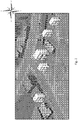
- image 200 shown in Fig. 2 comprising building 20.
- the front side of the building (marked by 23) is exposed in the displayed image allowing an APCS operator to point with an input device (e.g. mouse cursor) at any point located on the front side of the building (facing substantially the south-west direction).
- the APCS operator can thus direct the imaging device to point and/or zoom anywhere in the front side of the building.
- the APCS operator wishes to view the rear of the building (facing substantially the north-east direction) he is unable to do so, since the rear of the building is not exposed in the image and therefore the APCS operator is unable to point to the desired area.
- the APCS operator is required to contact control system 110 operator and request the operator to reposition the UAV to allow viewing the building from the desired direction.
- this process is inconvenient, time consuming and depends on the existence of an available communication link between control system 110 and APCS 140.
- an APCS graphical user interface configured to enable an UxV operator (e.g. an APCS operator) to direct the UxV to view a selected object from a desired viewing angle, notwithstanding the fact that the desired viewing angle of the object is not exposed in the displayed image.
- the graphical user interface is thus configured to operate in a "slave to icon” mode rather than the commonly known "slave to sensor mode”.
- a graphical user interface configured with a 3 dimensional (3D) graphical control tool.
- the 3D graphical control tool allows an APCS operator to place a graphical control icon in a desired position in a displayed image over a selected object, and use the icon for indicating, directly to the UxV, a desired viewing angle of the selected object.
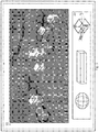
- Fig. 3 is a schematic illustration demonstrating an APCS operator console with a graphical user interface according to an example of the presently disclosed subject matter.
- Fig. 3 shows screen 31 of an operator console of APCS 140 displaying images captured by UAV 120. The displayed image shows the same screenshot shown earlier in fig. 2 .
- Fig. 3 also shows graphical control icon 33 of the 3D graphical control tool disclosed herein, which is displayed on screen 31.
- Graphical control icon can be displayed for example, in a toolbar control element 35.
- the toolbar can be integrated into the edge of screen 31 or a display window.
- the graphical control icon can be otherwise displayed in any way known in the art.
- Graphical control icon 33 can be configured as a 3D geometrical shape (e.g. polyhedron) which can be used by an APCS operator to mark an object of interest in a displayed image. For example, graphical control icon 33 can be dragged from its location in the toolbar control element to the screen and be placed over the object of interest, appearing as an external skeleton surrounding the object.
- the graphical control icon can be configured with resizable dimensions, which can be stretched or compressed to fit the size and shape of the selected object of interest.
- multiple icons having different selectable shapes and proportions can be made available (e.g. displayed on the toolbar) allowing the operator to conveniently select the most suitable icon for a given selected object.
- some icons can be pre-configured with the shapes of certain common objects which are likely to be selected in viewed images.
- a vehicle shaped icon can be provided for tracking vehicles.
- graphical control icon 33 can be drawn by APCS operator (e.g. with the help of a dedicated drawing tool) on top of the displayed image at the desired location.
- each face of the 3D graphical control icon assumes the representation of a respective real world face (or side) of the object as displayed in the image(s).
- pointing instructions can be generated by the APCS operator by pointing to a desired point on graphical control icon 33. Responsive to a pointing instruction generated with respect to the graphical control icon, a pointing command is generated with respect to the corresponding point on the object.
- the graphical control icon enables the APCS operator to generate pointing instructions for directing the UAV to observe any face of the selected object, including those not exposed in the displayed image.
- graphical control icon 33 can be manipulated by the APCS operator to change its orientation.
- the control icon which is placed in the image can be manipulated by the operator to change its orientation in all directions and thus expose, towards the operator, the faces of the control icon which represent hidden faces of the object that are not exposed in the displayed image.
- rotation around the center of the 3D graphical control icon 33 can be done by a left mouse button click followed by mouse dragging in the desired orientation and direction of rotation.
- This action exposes to the operator faces of the icon, representing the hidden faces of the respective object and allows the operator to interact and point to these faces.
- rotation of the graphical control icon may not be allowed in all directions.
- a graphical control icon assigned to a building may not be allowed to be rotated such that the bottom of the building, being in contact with the ground, is exposed.
- manipulation of the 3D graphical control icon can be done on a different icon than the one placed in the displayed image, such as a 3D graphical control icon located in the toolbar control element representing the icon placed in the displayed image.
- This solution allows maintaining the 3D graphical control icon in the image at the same orientation of the respective object while the toolbar icon is manipulated and turned in order to expose faces of the icon, representing the hidden faces of the respective object.
- a 3D graphical control icon is not necessarily placed over the selected object. Rather, once an object of interest is selected in a displayed image (e.g. by mouse clicking or otherwise marking the object) a respective 3D graphical control icon placed at a different location (not directly on the selected object, e.g. on the toolbar control element) is activated for receiving instructions with respect to the selected object, while the object itself in the image remains unchanged.
- Fig. 4 is a functional block diagram of a UAV operatively connected to a control unit, according to an example of the presently disclosed subject matter.
- Control unit 140 can be for example APCS.
- Fig. 4 shows UAV 120 comprising UAV onboard control unit 5, communication unit 9 and UAV flight control devices 15.
- UAV communication unit 9 is configured to provide a LOS and/or BLOS communication link with communication unit 41 of control unit 160.
- Communication between UAV 120 and the control unit can be realized by any suitable communication infrastructure and protocol known in the art.
- Communication unit 9 can comprise or be otherwise operatively connected to an aerial data terminal (B/LOS ADT) as described above.
- B/LOS ADT aerial data terminal
- the UAV onboard control unit 5 comprises data acquisition payload (sensing unit 10).
- the sensing unit can include an imaging device (e.g. a camera) configured for capturing images of a surveyed scene. These images can come from an electro-optic sensor which can provide for example, color optical images, black and white optical images, as well as infra-red image sensor, or any other types of imaging devices.
- an imaging device e.g. a camera
- electro-optic sensor can provide for example, color optical images, black and white optical images, as well as infra-red image sensor, or any other types of imaging devices.
- UAV onboard control unit further comprises a command processing module 12 and a command generator module 13.
- Command processing module 12 is configured to receive control-data and generate instructions for executing respective commands.
- control-data can include pointing instructions directed for pointing the image sensor in a desired direction.
- command processing unit 12 can generate and provide instructions to UAV flight control system 14 configured to control flight control devices for navigating the UAV to a desired position.
- command processing module 12 can be configured to determine whether the execution of a received pointing command requires repositioning of the UAV and if so, to generate instructions (e.g. with the help of command generator 13) to UAV flight control system 14 for controlling UAV flight control devices 15 in order to navigate the UAV to the desired location and provide the required images.
- UAV flight control devices include for example throttle, stabilizers, ailerons and rudders, configured for directing the UAV from its current position to a new desired position.
- UxVs different control devices exist depending on the specific type of vehicle.
- UAV flight control system 14 may include various control units, each dedicated for controlling the operation of a respective flight control device.
- control unit 160 (e.g. APCS 140), it comprises (in addition to communication unit 41) display unit 47, input device 49, command generator 43 and graphical engine 45.
- Display unit 47 comprises one or more display devices (e.g. one or more LED screens) for displaying received sensing-data received from UAV 120.
- Input device 49 is configured to enable an operator to interact with the control unit.
- Input device 49 includes for example, keyboard, joystick, computer mouse, touch pad, touch screen or any other device enabling operator-interaction with the control system.
- 3D graphical engine 45 is configured to generate and display the 3D graphical control tool for controlling the UAV.
- Command generator 43 is configured to generate control-data responsive to instructions received by an operator. For example, an APCS operator may interact with the control unit for generating pointing instructions directed for pointing the sensing unit to provide desired viewing angles of a selected object.
- Command generator 43 is configured to generate a respective pointing command based on the received pointing instructions.
- Fig. 5 is a flowchart of a sequence of operations carried out according to an example of the presently disclosed subject matter. Operations described with reference to Fig. 5 , can be executed, for example, with the help of a surveillance system configured according to the principles described above with reference to Fig. 4 . It is noted however that any description of operations which is made with reference to elements in Fig. 4 is done by way of example and for the purpose of illustration only and should not be construed as limiting in any way.
- the sensing unit onboard an UxV acquires images of a surveyed scene. Sensing-data comprising at least the captured images transmitted from the UxV is received at the control unit e.g. APCS 140 (block 501).
- the captured images may comprise one or more objects. For the purpose of providing a continuous video feed of the surveyed scene, images are continuously captured and continuously transmitted, and displayed at the control unit.
- one or more 3D graphical control icons are generated (e.g. with the help of 3D graphical engine 45) and displayed on the display device.
- graphical control icons can be automatically generated by graphical engine 45 and displayed by display unit 47.
- graphical control icons can be generated and displayed in a toolbar control element, making the icon available for use. The operator can then drag an appropriate icon and place it on an object of interest selected in the displayed images (or otherwise associate between the graphical control icon and the selected object).
- graphical control icons can be generated in response to a request or specific operation of an operator.
- control unit 160 can comprise an image processing module configured to determine the shape and possibly also size of the selected object and provide the graphical engine with instructions for generating an appropriate graphical control icon.
- an APCS operator can use input device 49 (configured together with the graphical engine as a drawing tool) for marking the outlines of an object of interest displayed in one or more images, and thus cause graphical engine 45 to generate a 3D graphical control icon according to the outline of the object, as marked by the operator.
- each face of the 3D graphical control icon assumes the representation of a respective real world face (or side) of the object as displayed in the image(s). Association between the faces of the object and the faces of the icon can be performed for example by graphical engine 45.
- graphical control icons are traced from an earlier image to a later image along a succession of captured images, thereby maintaining each graphical control icon associated with its respective object along the succession of images in the video stream.
- Methods of tracing objects from an earlier image to a later image along a succession of images are well known in the art and include for example a video motion detection algorithm (which enables tracing moving objects), center of gravity identification, edge detection, correlation etc.
- pointing instructions are received (e.g. from an operator) indicating desired viewing angles for viewing the selected object.
- the pointing instructions can be received by an operator using an input device for pointing on the 3D graphical control icon assigned to the selected object.
- Pointing instructions are processed by the control unit (e.g. with the help of command generator 43) and a respective command is generated and transmitted to the UxV (block 507).
- the control unit is initially configured to issue a centering command (e.g. with the help of command generator 43) instructing the UAV to position the selected object at the center of the displayed images.
- the received (pointing) command is processed (e.g. with the help of command processing module 12) to, inter alia, determine whether the respective pointing instructions require repositioning of the UxV (block 509).
- the pointing location on the 3D graphical control icon is considered and compared to the current position of the UxV.
- UxV position can be obtained from an onboard positioning such as a GPS receiver and/or INS.
- the dimensions (e.g. height) of the selected object can also be obtained from the viewed image and used for determining whether repositioning of the UxV is required.
- the graphical control icon can be manipulated by the operator in order to change its orientation (e.g. by turning the icon around its central axis in various directions) and thus expose, for interaction, areas of the icons which represent respective areas of the assigned object of interest which are not visible to the sensing unit and are thus not exposed in the displayed images.
- a pointing command is generated (block 513).
- the pointing command includes instructions for directing the image sensor to point in the desired direction. If an initial centering command has already brought the image sensor to point in the desired direction, no further commands are necessarily executed.
- a UAV repositioning command is generated (block 511).
- the repositioning command includes instructions for navigating the UAV to new position from which the desired point can be viewed by the image sensor.
- a pointing command can be generated in addition to the repositioning command for directing the sensing device towards a certain point.
- a pointing command (or a centering command) can be generated based on pointing instructions received from the operator after the UAV has reached its new position.
- control unit 160 can comprise command processing module 51 configured to execute operations as described above with reference to blocks 509 to 513. After the processing is completed, the respective command can be transmitted to the UxV where it can be executed.
- Received pointing commands are processed for generating instructions for directing the image sensor in a desired direction.
- Received UAV navigation (repositioning) commands are processed for generating instructions to the UAV fight control elements for navigating the UAV to a new position from which the desired point of view of the object can be obtained.
- While the presently disclosed subject matter provides an APCS operator with the ability to generate instructions directed to repositioning a UxV, in surveillance systems such as the one illustrated above with reference to fig. 1 , the operator of control system 110 can be maintained in the loop for controlling the UxV.
- the operator of control system 110 may have superseding commands over the APCS operator, and, accordingly may confirm or abort the APCS generated instructions before they are executed by the UxV.
- UxV In different flight scenarios, progression of a UxV is restricted by various restrictions.
- a UAV flight is sometimes restricted by no-flight zones (NFZ), which are areas over which aircraft are not permitted to fly.
- restricted airspace is an area (volume) of airspace in which air traffic is restricted.
- NFZ no-flight zones
- restricted airspace is an area (volume) of airspace in which air traffic is restricted.
- Such restrictions are commonly set up by authorities for military, security or safety reasons. For example, for national security reasons, aircraft are often allowed to cross borders between neighboring countries, only after being officially authorized to do so. In some cases, where the border delineates enemy territory, crossing of such a border may be altogether prohibited. Likewise, some aircraft (such as UAVs) are not allowed to fly over populated areas for human safety reasons.
- flight restrictions are related to the topography and/or the land cover in urban areas. For example, flight routes can be restricted in the vicinity of tall mountains or buildings to avoid the risk of collision.
- Another example of a flight restriction is related to the operation of an onboard camera.
- banking of the wings may position the UAV fuselage between the camera (located for example on the ventral side of the fuselage) and the direction of the earth, thus blocking the line of sight between the camera and the object(s) which are being captured. Note, that banking of the UAV directs the camera FOV away from the object of interest.
- the progression of a UGV can be restricted by the existence of holes, crevices or any other type of drops in the ground which may put the vehicle in danger.
- UAV flight control unit 14 can be configured to consider one or more flight restrictions and adapt the flight path of the UAV in order to avoid the violation of any possible restrictions.
- UAV flight control unit 14 can be configured, after determining the new position of the UAV, to consider available restrictions related data (being indicative of one or more restrictions) and adapt the flight path to the new position in order to avoid the violation of existing restrictions.
- UAV flight control unit 14 is configured to determine, based on priority data, whether the restriction supersede the repositioning command, or vice versa, and determine whether to execute the command accordingly.
- the operator of control system 110 may be responsible for determining whether the issued repositioning instructions should be executed or not.
- the presently disclosed subject matter contemplates a computer program implemented on a non-transitory computer useable medium being readable by a computer for executing the method of the presently disclosed subject matter.
- the presently disclosed subject matter further contemplates a computer-readable non-transitory computer memory tangibly embodying a program of instructions executable by the computer for executing the method of the presently disclosed subject matter.
- non-transitory is used herein to exclude transitory, propagating signals, but to otherwise include any volatile or non-volatile computer memory technology suitable to the application.
Landscapes
- Engineering & Computer Science (AREA)
- Physics & Mathematics (AREA)
- General Physics & Mathematics (AREA)
- Remote Sensing (AREA)
- Radar, Positioning & Navigation (AREA)
- Theoretical Computer Science (AREA)
- Aviation & Aerospace Engineering (AREA)
- Automation & Control Theory (AREA)
- General Engineering & Computer Science (AREA)
- Human Computer Interaction (AREA)
- Computing Systems (AREA)
- Mathematical Physics (AREA)
- Business, Economics & Management (AREA)
- Evolutionary Computation (AREA)
- Game Theory and Decision Science (AREA)
- Medical Informatics (AREA)
- Artificial Intelligence (AREA)
- Health & Medical Sciences (AREA)
- Astronomy & Astrophysics (AREA)
- Multimedia (AREA)
- Closed-Circuit Television Systems (AREA)
Claims (13)
- Überwachungssystem, umfassend:eine Steuereinheit (160) für unbemanntes Fahrzeug (UxV), die konfiguriert ist, um über eine Kommunikationsverbindung mit einem UxV (120) zu kommunizieren; das UxV umfassend eine Erfassungseinheit (10), die konfiguriert ist, um ein oder mehrere Bilder eines überwachten Bereichs zu erfassen und die Bilder an die UxV-Steuereinheit (160) zu übertragen; wobei die UxV-Steuereinheit konfiguriert ist, um das eine oder die mehreren Bilder auf einer Anzeigevorrichtung (47) anzuzeigen;wobei das Überwachungssystem dadurch gekennzeichnet ist, dass die UxV-Steuereinheit (160) ferner konfiguriert ist, um als Reaktion auf empfangene Daten, die indikativ für ein ausgewähltes Objekt (20) in dem einen oder den mehreren Bildern sind, dem ausgewählten Objekt ein grafisches Bediensymbol (33) zuzuweisen; wobei das grafische Bediensymbol eine 3D-Darstellung des ausgewählten Objekts (20) ist, wobei verschiedene Flächen des ausgewählten Objekts (20) verschiedenen jeweiligen Flächen des grafischen Bediensymbols (33) zugewiesen sind;wobei das grafische Bediensymbol (33) in der Lage ist, von einem Bediener interagiert zu werden, um seine Ausrichtung zu ändern und dadurch Bereiche des Bediensymbols (33) gegenüber dem Bediener freizulegen, die jeweilige Bereiche des ausgewählten Objekts (20) darstellen, die in dem einen oder den mehreren auf der Anzeigevorrichtung angezeigten Bildern nicht freigelegt sind, und dadurch zu ermöglichen, Anweisungen in Bezug auf die Bereiche zu erzeugen, die in dem einen oder den mehreren Bildern nicht freigelegt sind;wobei das Überwachungssystem ferner konfiguriert ist, um auf die Interaktion eines Bedieners mit dem Bediensymbol zum Anzeigen gewünschter Betrachtungswinkel des ausgewählten Objekts (20) zu reagieren, um:
zu bestimmen, ob die Betrachtung des ausgewählten Objekts (20) in den gewünschten Betrachtungswinkeln eine Neupositionierung des UxV erfordert, und wenn ja, Anweisungen zum Neupositionieren des UxV (120) zu erzeugen, damit die Erfassungseinheit (10) das Objekt in den gewünschten Betrachtungswinkeln betrachten kann. - System nach Anspruch 1, ferner umfassend eine Bordsteuereinheit (5), die an Bord eines UxV montiert werden kann und konfiguriert ist, um das Bestimmen, ob das Betrachten des ausgewählten Objekts unter den gewünschten Betrachtungswinkeln ein Neupositionieren des UxV erfordert, und das Erzeugen von Anweisungen zum Neupositionieren des UxV auszuführen.
- System nach Anspruch 1, wobei die UxV-Steuereinheit (160) konfiguriert ist, um das Bestimmen auszuführen, ob das Betrachten des ausgewählten Objekts (20) unter den gewünschten Betrachtungswinkeln ein Neupositionieren des UxV erfordert.
- System nach einem der Ansprüche 1 bis 3, wobei die UxV-Steuereinheit (160) konfiguriert ist, um als Reaktion auf empfangene Daten, die ein ausgewähltes Objekt (20) in dem einen oder den mehreren Bildern anzeigen, das grafische Bediensymbol entsprechend der Form und Größe des ausgewählten Objekts zu erzeugen.
- System nach einem der Ansprüche 1 bis 3, wobei das grafische Bediensymbol (33) ein wählbares und in der Größe veränderbares Symbol ist, das an die Form und Größe des ausgewählten Objekts angepasst werden kann.
- System nach einem der Ansprüche 1 bis 3, wobei die UxV-Steuereinheit (160) ein Zeichnen-Tool umfasst, das konfiguriert ist, um den Bediener zu ermöglichen, das grafische Bediensymbol (33) um das ausgewählte Objekt zu zeichnen.
- System nach einem der Ansprüche 1 bis 6, wobei das eine oder die mehreren Bilder eine Abfolge von Bildern in einem Videostreaming sind; das Überwachungssystem ferner konfiguriert ist, um grafische Bediensymbole von einem früheren Bild zu einem späteren Bild entlang der Abfolge von Bildern zu verfolgen, wodurch jedes grafische Bediensymbol mit seinem zugewiesenen Objekt entlang der Abfolge von Bildern in dem Videostreaming assoziiert bleibt.
- System nach einem der vorherigen Ansprüche, ferner umfassend das UxV, wobei das UxV ein unbemanntes Luftfahrzeug (120) ist.
- Computergestütztes Verfahren zum Steuern eines unbemannten Fahrzeugs (UxV) (120) in einem Überwachungssystem; das Überwachungssystem umfassend eine UxV-Steuereinheit (160), die konfiguriert ist, um über eine Kommunikationsverbindung mit einem UxV zu kommunizieren; das UxV umfassend eine Erfassungseinheit, die konfiguriert ist, um ein oder mehrere Bilder eines überwachten Bereichs zu erfassen und die Bilder an die UxV-Steuereinheit zu übertragen; wobei die UxV-Steuereinheit konfiguriert ist, um das eine oder die mehreren Bilder auf einer Anzeigevorrichtung (47) anzuzeigen;
wobei das Verfahren durch Verwenden von einem oder mehreren Prozessoren gekennzeichnet ist, um:als Reaktion auf Daten, die an der Steuereinheit empfangen werden, die ein ausgewähltes Objekt (20) in dem einen oder den mehreren Bildern anzeigen, ein grafischen Bediensymbols zu dem ausgewählten Objekt zuzuweisen; wobei das grafische Bediensymbol (33) eine 3D-Darstellung des ausgewählten Objekts ist, wobei verschiedene Flächen des ausgewählten Objekts verschiedenen jeweiligen Flächen des grafischen Bediensymbols (33) zugewiesen sind;wobei das grafische Bediensymbol (33) in der Lage ist, von einem Bediener interagiert zu werden, um seine Ausrichtung zu ändern und dadurch Bereiche des Bediensymbols (33) gegenüber dem Bediener freizulegen, die jeweilige Bereiche des ausgewählten Objekts (20) darstellen, die in dem einen oder den mehreren auf der Anzeigevorrichtung angezeigten Bildern nicht freigelegt sind, und dadurch zu ermöglichen, Anweisungen in Bezug auf die Bereiche zu erzeugen, die in dem einen oder den mehreren Bildern nicht freigelegt sind;als Reaktion auf eine Interaktion eines Bedieners mit dem Bediensymbol zum Anzeigen gewünschter Betrachtungswinkel des ausgewählten Objekts (20), zu bestimmen, ob ein Betrachten des ausgewählten Objekts (20) unter den gewünschten Betrachtungswinkeln ein Neupositionieren des UxV erfordert; und wenn dies der Fall ist,Anweisungen zum Neupositionieren des UxV (120) zu erzeugen, damit die Erfassungseinheit das Objekt unter den gewünschten Blickwinkeln betrachten kann. - Verfahren nach Anspruch 9, wobei das Bestimmen, ob ein Betrachten des ausgewählten Objekts unter den gewünschten Betrachtungswinkeln ein Neupositionieren des UxV (120) und das Erzeugen von Anweisungen erfordert, von einer Steuereinheit (5) ausgeführt wird, die an der UxV (120) montiert werden kann.
- Verfahren nach einem der Ansprüche 9 bis 10,ferner umfassend: als Reaktion auf empfangene Daten, die indikativ für ein ausgewähltes Objekt in dem einen oder den mehreren Bildern sind, Erzeugen des grafischen Bediensymbols entsprechend der Form und Größe des ausgewählten Objekts (20).
- Verfahren nach einem der Ansprüche 9 bis 11, wobei das eine oder die mehreren Bilder eine Abfolge von Bildern in einem Videostreaming sind; das Verfahren ferner umfassend:
Verfolgen der grafischen Bediensymbole von einem früheren Bild zu einem späteren Bild entlang der Abfolge von Bildern, wodurch jedes grafische Bediensymbol mit seinem zugewiesenen Objekt entlang der Abfolge von Bildern in dem Videostreaming assoziiert bleibt. - Computerlesbare Datenspeichervorrichtung, umfassend ein Programm von Anweisungen, die von dem Computer zum Ausführen des Verfahrens nach Anspruch 9 ausgeführt werden können.
Applications Claiming Priority (2)
| Application Number | Priority Date | Filing Date | Title |
|---|---|---|---|
| IL238318A IL238318B (en) | 2015-04-16 | 2015-04-16 | Control interface for uxv |
| PCT/IL2016/050358 WO2016166745A1 (en) | 2015-04-16 | 2016-04-03 | Control interface for uxv |
Publications (3)
| Publication Number | Publication Date |
|---|---|
| EP3283368A1 EP3283368A1 (de) | 2018-02-21 |
| EP3283368A4 EP3283368A4 (de) | 2018-12-26 |
| EP3283368B1 true EP3283368B1 (de) | 2021-07-28 |
Family
ID=57125837
Family Applications (1)
| Application Number | Title | Priority Date | Filing Date |
|---|---|---|---|
| EP16779702.6A Active EP3283368B1 (de) | 2015-04-16 | 2016-04-03 | Grafische benutzerschnittstelle für uxv |
Country Status (6)
| Country | Link |
|---|---|
| US (1) | US10429834B2 (de) |
| EP (1) | EP3283368B1 (de) |
| ES (1) | ES2892489T3 (de) |
| IL (1) | IL238318B (de) |
| SG (1) | SG11201707171WA (de) |
| WO (1) | WO2016166745A1 (de) |
Families Citing this family (5)
| Publication number | Priority date | Publication date | Assignee | Title |
|---|---|---|---|---|
| US10553122B1 (en) * | 2016-03-22 | 2020-02-04 | Amazon Technologies, Inc. | Unmanned aerial vehicle data collection for routing |
| JP6688901B2 (ja) * | 2016-10-17 | 2020-04-28 | エスゼット ディージェイアイ テクノロジー カンパニー リミテッドSz Dji Technology Co.,Ltd | 3次元形状推定方法、3次元形状推定システム、飛行体、プログラム、及び記録媒体 |
| KR102681582B1 (ko) * | 2017-01-05 | 2024-07-05 | 삼성전자주식회사 | 전자 장치 및 그 제어 방법 |
| CN107396051A (zh) * | 2017-08-09 | 2017-11-24 | 广州云从信息科技有限公司 | 一种采用无人机进行人脸识别监控的方法 |
| AT522653B1 (de) * | 2019-05-15 | 2025-12-15 | Wittmann Tech Gmbh | Verfahren zur Darstellung und Bedienung von Produktionsmitteln, insbesondere für die kunststoffverarbeitende Industrie |
Family Cites Families (22)
| Publication number | Priority date | Publication date | Assignee | Title |
|---|---|---|---|---|
| US5521817A (en) * | 1994-08-08 | 1996-05-28 | Honeywell Inc. | Airborne drone formation control system |
| US6584382B2 (en) | 2000-05-17 | 2003-06-24 | Abraham E. Karem | Intuitive vehicle and machine control |
| US6925382B2 (en) | 2000-10-16 | 2005-08-02 | Richard H. Lahn | Remote image management system (RIMS) |
| US6732024B2 (en) * | 2001-05-07 | 2004-05-04 | The Board Of Trustees Of The Leland Stanford Junior University | Method and apparatus for vehicle control, navigation and positioning |
| US6963795B2 (en) * | 2002-07-16 | 2005-11-08 | Honeywell Interntaional Inc. | Vehicle position keeping system |
| SE0300871D0 (sv) * | 2003-03-27 | 2003-03-27 | Saab Ab | Waypoint navigation |
| US7911497B2 (en) | 2003-04-25 | 2011-03-22 | Lockheed Martin Corporation | Method and apparatus for video on demand |
| WO2005076967A2 (en) * | 2004-02-06 | 2005-08-25 | Icosystem Corporation | Methods and systems for area search using a plurality of unmanned vehicles |
| JP2005339746A (ja) * | 2004-05-31 | 2005-12-08 | Pioneer Electronic Corp | 圧縮データファイルの付加情報読込方法およびその方法を実行するプログラム |
| US7418320B1 (en) * | 2005-01-24 | 2008-08-26 | International Business Machines Corporation | Navigating a UAV having an on-board digital camera to capture desired geographic area |
| US20080144884A1 (en) | 2006-07-20 | 2008-06-19 | Babak Habibi | System and method of aerial surveillance |
| US8718838B2 (en) | 2007-12-14 | 2014-05-06 | The Boeing Company | System and methods for autonomous tracking and surveillance |
| US8170840B2 (en) | 2008-10-31 | 2012-05-01 | Eagle View Technologies, Inc. | Pitch determination systems and methods for aerial roof estimation |
| US20100228406A1 (en) | 2009-03-03 | 2010-09-09 | Honeywell International Inc. | UAV Flight Control Method And System |
| US8977407B2 (en) | 2009-05-27 | 2015-03-10 | Honeywell International Inc. | Adaptive user interface for semi-automatic operation |
| FR2957266B1 (fr) | 2010-03-11 | 2012-04-20 | Parrot | Procede et appareil de telecommande d'un drone, notamment d'un drone a voilure tournante. |
| US8965598B2 (en) | 2010-09-30 | 2015-02-24 | Empire Technology Development Llc | Automatic flight control for UAV based solid modeling |
| EP2538298A1 (de) * | 2011-06-22 | 2012-12-26 | Sensefly Sàrl | Verfahren zur Erfassung von Bildern aus beliebigen Perspektiven mithilfe von mit festen Bildgebern ausgestatteten UAV |
| FR2985581B1 (fr) | 2012-01-05 | 2014-11-28 | Parrot | Procede de pilotage d'un drone a voilure tournante pour operer une prise de vue par une camera embarquee avec minimisation des mouvements perturbateurs |
| NO334183B1 (no) | 2012-03-22 | 2014-01-13 | Prox Dynamics As | Metode og anordning for å kontrollere og overvåke det omliggende område til et ubemannet luftfartøy |
| US9002719B2 (en) * | 2012-10-08 | 2015-04-07 | State Farm Mutual Automobile Insurance Company | Device and method for building claim assessment |
| US8903568B1 (en) | 2013-07-31 | 2014-12-02 | SZ DJI Technology Co., Ltd | Remote control method and terminal |
-
2015
- 2015-04-16 IL IL238318A patent/IL238318B/en active IP Right Grant
-
2016
- 2016-04-03 EP EP16779702.6A patent/EP3283368B1/de active Active
- 2016-04-03 ES ES16779702T patent/ES2892489T3/es active Active
- 2016-04-03 US US15/557,985 patent/US10429834B2/en active Active
- 2016-04-03 SG SG11201707171WA patent/SG11201707171WA/en unknown
- 2016-04-03 WO PCT/IL2016/050358 patent/WO2016166745A1/en not_active Ceased
Non-Patent Citations (1)
| Title |
|---|
| None * |
Also Published As
| Publication number | Publication date |
|---|---|
| EP3283368A4 (de) | 2018-12-26 |
| SG11201707171WA (en) | 2017-10-30 |
| IL238318B (en) | 2020-09-30 |
| ES2892489T3 (es) | 2022-02-04 |
| EP3283368A1 (de) | 2018-02-21 |
| US20180046178A1 (en) | 2018-02-15 |
| US10429834B2 (en) | 2019-10-01 |
| WO2016166745A1 (en) | 2016-10-20 |
Similar Documents
| Publication | Publication Date | Title |
|---|---|---|
| US11361665B2 (en) | Unmanned aerial vehicle privacy controls | |
| US11897607B2 (en) | Unmanned aerial vehicle beyond visual line of sight control | |
| US8229163B2 (en) | 4D GIS based virtual reality for moving target prediction | |
| CN107924638B (zh) | 用于云台模拟的系统和方法 | |
| JP6964786B2 (ja) | レーダー作動のための自動カメラ駆動型航空機制御 | |
| US12254779B2 (en) | Unmanned aerial vehicle privacy controls | |
| EP4273656B1 (de) | Vorrichtung, verfahren und software zur unterstützung eines bedieners beim fliegen einer drohne unter verwendung einer fernbedienung und ar brille | |
| US10429834B2 (en) | Control interface for UxV | |
| WO2017139282A1 (en) | Unmanned aerial vehicle privacy controls | |
| CN105518555A (zh) | 目标追踪系统及方法 | |
| WO2019061334A1 (en) | SYSTEMS AND METHODS FOR PROCESSING AND DISPLAYING IMAGE DATA BASED ON ATTITUDE INFORMATION | |
| WO2018023736A1 (en) | System and method for positioning a movable object | |
| WO2017147142A1 (en) | Unmanned aerial vehicle visual line of sight control | |
| KR20250158216A (ko) | 무인이동체 운용 시스템 | |
| JP2023083072A (ja) | 方法、システムおよびプログラム | |
| WO2021090312A2 (en) | Line of sight maintenance during object tracking |
Legal Events
| Date | Code | Title | Description |
|---|---|---|---|
| STAA | Information on the status of an ep patent application or granted ep patent |
Free format text: STATUS: THE INTERNATIONAL PUBLICATION HAS BEEN MADE |
|
| PUAI | Public reference made under article 153(3) epc to a published international application that has entered the european phase |
Free format text: ORIGINAL CODE: 0009012 |
|
| STAA | Information on the status of an ep patent application or granted ep patent |
Free format text: STATUS: REQUEST FOR EXAMINATION WAS MADE |
|
| 17P | Request for examination filed |
Effective date: 20171115 |
|
| AK | Designated contracting states |
Kind code of ref document: A1 Designated state(s): AL AT BE BG CH CY CZ DE DK EE ES FI FR GB GR HR HU IE IS IT LI LT LU LV MC MK MT NL NO PL PT RO RS SE SI SK SM TR |
|
| AX | Request for extension of the european patent |
Extension state: BA ME |
|
| DAV | Request for validation of the european patent (deleted) | ||
| DAX | Request for extension of the european patent (deleted) | ||
| A4 | Supplementary search report drawn up and despatched |
Effective date: 20181123 |
|
| RIC1 | Information provided on ipc code assigned before grant |
Ipc: B64C 19/00 20060101AFI20181119BHEP Ipc: B64C 39/02 20060101ALI20181119BHEP Ipc: G06K 9/00 20060101ALI20181119BHEP Ipc: G06F 3/0481 20130101ALI20181119BHEP Ipc: G05D 1/00 20060101ALI20181119BHEP Ipc: G06T 17/10 20060101ALI20181119BHEP |
|
| STAA | Information on the status of an ep patent application or granted ep patent |
Free format text: STATUS: EXAMINATION IS IN PROGRESS |
|
| 17Q | First examination report despatched |
Effective date: 20191002 |
|
| GRAP | Despatch of communication of intention to grant a patent |
Free format text: ORIGINAL CODE: EPIDOSNIGR1 |
|
| STAA | Information on the status of an ep patent application or granted ep patent |
Free format text: STATUS: GRANT OF PATENT IS INTENDED |
|
| INTG | Intention to grant announced |
Effective date: 20210318 |
|
| GRAS | Grant fee paid |
Free format text: ORIGINAL CODE: EPIDOSNIGR3 |
|
| GRAA | (expected) grant |
Free format text: ORIGINAL CODE: 0009210 |
|
| STAA | Information on the status of an ep patent application or granted ep patent |
Free format text: STATUS: THE PATENT HAS BEEN GRANTED |
|
| AK | Designated contracting states |
Kind code of ref document: B1 Designated state(s): AL AT BE BG CH CY CZ DE DK EE ES FI FR GB GR HR HU IE IS IT LI LT LU LV MC MK MT NL NO PL PT RO RS SE SI SK SM TR |
|
| REG | Reference to a national code |
Ref country code: GB Ref legal event code: FG4D |
|
| REG | Reference to a national code |
Ref country code: CH Ref legal event code: EP |
|
| REG | Reference to a national code |
Ref country code: AT Ref legal event code: REF Ref document number: 1414538 Country of ref document: AT Kind code of ref document: T Effective date: 20210815 |
|
| REG | Reference to a national code |
Ref country code: IE Ref legal event code: FG4D |
|
| REG | Reference to a national code |
Ref country code: DE Ref legal event code: R096 Ref document number: 602016061273 Country of ref document: DE |
|
| REG | Reference to a national code |
Ref country code: LT Ref legal event code: MG9D |
|
| REG | Reference to a national code |
Ref country code: NL Ref legal event code: MP Effective date: 20210728 |
|
| REG | Reference to a national code |
Ref country code: GR Ref legal event code: EP Ref document number: 20210402825 Country of ref document: GR Effective date: 20211209 |
|
| REG | Reference to a national code |
Ref country code: AT Ref legal event code: MK05 Ref document number: 1414538 Country of ref document: AT Kind code of ref document: T Effective date: 20210728 |
|
| PG25 | Lapsed in a contracting state [announced via postgrant information from national office to epo] |
Ref country code: RS Free format text: LAPSE BECAUSE OF FAILURE TO SUBMIT A TRANSLATION OF THE DESCRIPTION OR TO PAY THE FEE WITHIN THE PRESCRIBED TIME-LIMIT Effective date: 20210728 Ref country code: SE Free format text: LAPSE BECAUSE OF FAILURE TO SUBMIT A TRANSLATION OF THE DESCRIPTION OR TO PAY THE FEE WITHIN THE PRESCRIBED TIME-LIMIT Effective date: 20210728 Ref country code: LT Free format text: LAPSE BECAUSE OF FAILURE TO SUBMIT A TRANSLATION OF THE DESCRIPTION OR TO PAY THE FEE WITHIN THE PRESCRIBED TIME-LIMIT Effective date: 20210728 Ref country code: AT Free format text: LAPSE BECAUSE OF FAILURE TO SUBMIT A TRANSLATION OF THE DESCRIPTION OR TO PAY THE FEE WITHIN THE PRESCRIBED TIME-LIMIT Effective date: 20210728 Ref country code: BG Free format text: LAPSE BECAUSE OF FAILURE TO SUBMIT A TRANSLATION OF THE DESCRIPTION OR TO PAY THE FEE WITHIN THE PRESCRIBED TIME-LIMIT Effective date: 20211028 Ref country code: NL Free format text: LAPSE BECAUSE OF FAILURE TO SUBMIT A TRANSLATION OF THE DESCRIPTION OR TO PAY THE FEE WITHIN THE PRESCRIBED TIME-LIMIT Effective date: 20210728 Ref country code: NO Free format text: LAPSE BECAUSE OF FAILURE TO SUBMIT A TRANSLATION OF THE DESCRIPTION OR TO PAY THE FEE WITHIN THE PRESCRIBED TIME-LIMIT Effective date: 20211028 Ref country code: PT Free format text: LAPSE BECAUSE OF FAILURE TO SUBMIT A TRANSLATION OF THE DESCRIPTION OR TO PAY THE FEE WITHIN THE PRESCRIBED TIME-LIMIT Effective date: 20211129 Ref country code: HR Free format text: LAPSE BECAUSE OF FAILURE TO SUBMIT A TRANSLATION OF THE DESCRIPTION OR TO PAY THE FEE WITHIN THE PRESCRIBED TIME-LIMIT Effective date: 20210728 Ref country code: FI Free format text: LAPSE BECAUSE OF FAILURE TO SUBMIT A TRANSLATION OF THE DESCRIPTION OR TO PAY THE FEE WITHIN THE PRESCRIBED TIME-LIMIT Effective date: 20210728 |
|
| REG | Reference to a national code |
Ref country code: ES Ref legal event code: FG2A Ref document number: 2892489 Country of ref document: ES Kind code of ref document: T3 Effective date: 20220204 |
|
| PG25 | Lapsed in a contracting state [announced via postgrant information from national office to epo] |
Ref country code: PL Free format text: LAPSE BECAUSE OF FAILURE TO SUBMIT A TRANSLATION OF THE DESCRIPTION OR TO PAY THE FEE WITHIN THE PRESCRIBED TIME-LIMIT Effective date: 20210728 Ref country code: LV Free format text: LAPSE BECAUSE OF FAILURE TO SUBMIT A TRANSLATION OF THE DESCRIPTION OR TO PAY THE FEE WITHIN THE PRESCRIBED TIME-LIMIT Effective date: 20210728 |
|
| PG25 | Lapsed in a contracting state [announced via postgrant information from national office to epo] |
Ref country code: DK Free format text: LAPSE BECAUSE OF FAILURE TO SUBMIT A TRANSLATION OF THE DESCRIPTION OR TO PAY THE FEE WITHIN THE PRESCRIBED TIME-LIMIT Effective date: 20210728 |
|
| REG | Reference to a national code |
Ref country code: DE Ref legal event code: R097 Ref document number: 602016061273 Country of ref document: DE |
|
| PG25 | Lapsed in a contracting state [announced via postgrant information from national office to epo] |
Ref country code: SM Free format text: LAPSE BECAUSE OF FAILURE TO SUBMIT A TRANSLATION OF THE DESCRIPTION OR TO PAY THE FEE WITHIN THE PRESCRIBED TIME-LIMIT Effective date: 20210728 Ref country code: SK Free format text: LAPSE BECAUSE OF FAILURE TO SUBMIT A TRANSLATION OF THE DESCRIPTION OR TO PAY THE FEE WITHIN THE PRESCRIBED TIME-LIMIT Effective date: 20210728 Ref country code: RO Free format text: LAPSE BECAUSE OF FAILURE TO SUBMIT A TRANSLATION OF THE DESCRIPTION OR TO PAY THE FEE WITHIN THE PRESCRIBED TIME-LIMIT Effective date: 20210728 Ref country code: EE Free format text: LAPSE BECAUSE OF FAILURE TO SUBMIT A TRANSLATION OF THE DESCRIPTION OR TO PAY THE FEE WITHIN THE PRESCRIBED TIME-LIMIT Effective date: 20210728 Ref country code: CZ Free format text: LAPSE BECAUSE OF FAILURE TO SUBMIT A TRANSLATION OF THE DESCRIPTION OR TO PAY THE FEE WITHIN THE PRESCRIBED TIME-LIMIT Effective date: 20210728 Ref country code: AL Free format text: LAPSE BECAUSE OF FAILURE TO SUBMIT A TRANSLATION OF THE DESCRIPTION OR TO PAY THE FEE WITHIN THE PRESCRIBED TIME-LIMIT Effective date: 20210728 |
|
| PLBE | No opposition filed within time limit |
Free format text: ORIGINAL CODE: 0009261 |
|
| STAA | Information on the status of an ep patent application or granted ep patent |
Free format text: STATUS: NO OPPOSITION FILED WITHIN TIME LIMIT |
|
| 26N | No opposition filed |
Effective date: 20220429 |
|
| PG25 | Lapsed in a contracting state [announced via postgrant information from national office to epo] |
Ref country code: IT Free format text: LAPSE BECAUSE OF FAILURE TO SUBMIT A TRANSLATION OF THE DESCRIPTION OR TO PAY THE FEE WITHIN THE PRESCRIBED TIME-LIMIT Effective date: 20210728 |
|
| REG | Reference to a national code |
Ref country code: CH Ref legal event code: PL |
|
| GBPC | Gb: european patent ceased through non-payment of renewal fee |
Effective date: 20220403 |
|
| REG | Reference to a national code |
Ref country code: BE Ref legal event code: MM Effective date: 20220430 |
|
| PG25 | Lapsed in a contracting state [announced via postgrant information from national office to epo] |
Ref country code: MC Free format text: LAPSE BECAUSE OF FAILURE TO SUBMIT A TRANSLATION OF THE DESCRIPTION OR TO PAY THE FEE WITHIN THE PRESCRIBED TIME-LIMIT Effective date: 20210728 Ref country code: LU Free format text: LAPSE BECAUSE OF NON-PAYMENT OF DUE FEES Effective date: 20220403 Ref country code: LI Free format text: LAPSE BECAUSE OF NON-PAYMENT OF DUE FEES Effective date: 20220430 Ref country code: GB Free format text: LAPSE BECAUSE OF NON-PAYMENT OF DUE FEES Effective date: 20220403 Ref country code: CH Free format text: LAPSE BECAUSE OF NON-PAYMENT OF DUE FEES Effective date: 20220430 |
|
| PG25 | Lapsed in a contracting state [announced via postgrant information from national office to epo] |
Ref country code: BE Free format text: LAPSE BECAUSE OF NON-PAYMENT OF DUE FEES Effective date: 20220430 |
|
| PG25 | Lapsed in a contracting state [announced via postgrant information from national office to epo] |
Ref country code: IE Free format text: LAPSE BECAUSE OF NON-PAYMENT OF DUE FEES Effective date: 20220403 |
|
| PG25 | Lapsed in a contracting state [announced via postgrant information from national office to epo] |
Ref country code: HU Free format text: LAPSE BECAUSE OF FAILURE TO SUBMIT A TRANSLATION OF THE DESCRIPTION OR TO PAY THE FEE WITHIN THE PRESCRIBED TIME-LIMIT; INVALID AB INITIO Effective date: 20160403 |
|
| PG25 | Lapsed in a contracting state [announced via postgrant information from national office to epo] |
Ref country code: MK Free format text: LAPSE BECAUSE OF FAILURE TO SUBMIT A TRANSLATION OF THE DESCRIPTION OR TO PAY THE FEE WITHIN THE PRESCRIBED TIME-LIMIT Effective date: 20210728 Ref country code: CY Free format text: LAPSE BECAUSE OF FAILURE TO SUBMIT A TRANSLATION OF THE DESCRIPTION OR TO PAY THE FEE WITHIN THE PRESCRIBED TIME-LIMIT Effective date: 20210728 |
|
| PG25 | Lapsed in a contracting state [announced via postgrant information from national office to epo] |
Ref country code: MT Free format text: LAPSE BECAUSE OF FAILURE TO SUBMIT A TRANSLATION OF THE DESCRIPTION OR TO PAY THE FEE WITHIN THE PRESCRIBED TIME-LIMIT Effective date: 20210728 |
|
| PGFP | Annual fee paid to national office [announced via postgrant information from national office to epo] |
Ref country code: GR Payment date: 20250318 Year of fee payment: 10 |
|
| PGFP | Annual fee paid to national office [announced via postgrant information from national office to epo] |
Ref country code: FR Payment date: 20250210 Year of fee payment: 10 |
|
| PGFP | Annual fee paid to national office [announced via postgrant information from national office to epo] |
Ref country code: DE Payment date: 20250204 Year of fee payment: 10 |
|
| PGFP | Annual fee paid to national office [announced via postgrant information from national office to epo] |
Ref country code: ES Payment date: 20250506 Year of fee payment: 10 |
|
| PG25 | Lapsed in a contracting state [announced via postgrant information from national office to epo] |
Ref country code: TR Free format text: LAPSE BECAUSE OF FAILURE TO SUBMIT A TRANSLATION OF THE DESCRIPTION OR TO PAY THE FEE WITHIN THE PRESCRIBED TIME-LIMIT Effective date: 20210728 |