EP3283853B1 - Capteur pour déterminer au moins un paramètre d'un milieu fluide s'écoulant dans un conduit de mesure - Google Patents
Capteur pour déterminer au moins un paramètre d'un milieu fluide s'écoulant dans un conduit de mesure Download PDFInfo
- Publication number
- EP3283853B1 EP3283853B1 EP16706205.8A EP16706205A EP3283853B1 EP 3283853 B1 EP3283853 B1 EP 3283853B1 EP 16706205 A EP16706205 A EP 16706205A EP 3283853 B1 EP3283853 B1 EP 3283853B1
- Authority
- EP
- European Patent Office
- Prior art keywords
- sensor
- electronics compartment
- compartment cover
- electronics
- projection
- Prior art date
- Legal status (The legal status is an assumption and is not a legal conclusion. Google has not performed a legal analysis and makes no representation as to the accuracy of the status listed.)
- Active
Links
Images

Classifications
-
- G—PHYSICS
- G01—MEASURING; TESTING
- G01F—MEASURING VOLUME, VOLUME FLOW, MASS FLOW OR LIQUID LEVEL; METERING BY VOLUME
- G01F1/00—Measuring the volume flow or mass flow of fluid or fluent solid material wherein the fluid passes through a meter in a continuous flow
- G01F1/68—Measuring the volume flow or mass flow of fluid or fluent solid material wherein the fluid passes through a meter in a continuous flow by using thermal effects
- G01F1/684—Structural arrangements; Mounting of elements, e.g. in relation to fluid flow
- G01F1/6847—Structural arrangements; Mounting of elements, e.g. in relation to fluid flow where sensing or heating elements are not disturbing the fluid flow, e.g. elements mounted outside the flow duct
-
- G—PHYSICS
- G01—MEASURING; TESTING
- G01F—MEASURING VOLUME, VOLUME FLOW, MASS FLOW OR LIQUID LEVEL; METERING BY VOLUME
- G01F1/00—Measuring the volume flow or mass flow of fluid or fluent solid material wherein the fluid passes through a meter in a continuous flow
- G01F1/68—Measuring the volume flow or mass flow of fluid or fluent solid material wherein the fluid passes through a meter in a continuous flow by using thermal effects
-
- G—PHYSICS
- G01—MEASURING; TESTING
- G01F—MEASURING VOLUME, VOLUME FLOW, MASS FLOW OR LIQUID LEVEL; METERING BY VOLUME
- G01F1/00—Measuring the volume flow or mass flow of fluid or fluent solid material wherein the fluid passes through a meter in a continuous flow
- G01F1/68—Measuring the volume flow or mass flow of fluid or fluent solid material wherein the fluid passes through a meter in a continuous flow by using thermal effects
- G01F1/684—Structural arrangements; Mounting of elements, e.g. in relation to fluid flow
- G01F1/6842—Structural arrangements; Mounting of elements, e.g. in relation to fluid flow with means for influencing the fluid flow
-
- G—PHYSICS
- G01—MEASURING; TESTING
- G01F—MEASURING VOLUME, VOLUME FLOW, MASS FLOW OR LIQUID LEVEL; METERING BY VOLUME
- G01F5/00—Measuring a proportion of the volume flow
-
- F—MECHANICAL ENGINEERING; LIGHTING; HEATING; WEAPONS; BLASTING
- F02—COMBUSTION ENGINES; HOT-GAS OR COMBUSTION-PRODUCT ENGINE PLANTS
- F02D—CONTROLLING COMBUSTION ENGINES
- F02D41/00—Electrical control of supply of combustible mixture or its constituents
- F02D41/02—Circuit arrangements for generating control signals
- F02D41/18—Circuit arrangements for generating control signals by measuring intake air flow
-
- F—MECHANICAL ENGINEERING; LIGHTING; HEATING; WEAPONS; BLASTING
- F02—COMBUSTION ENGINES; HOT-GAS OR COMBUSTION-PRODUCT ENGINE PLANTS
- F02M—SUPPLYING COMBUSTION ENGINES IN GENERAL WITH COMBUSTIBLE MIXTURES OR CONSTITUENTS THEREOF
- F02M35/00—Combustion-air cleaners, air intakes, intake silencers, or induction systems specially adapted for, or arranged on, internal-combustion engines
- F02M35/10—Air intakes; Induction systems
- F02M35/10373—Sensors for intake systems
- F02M35/10386—Sensors for intake systems for flow rate
Definitions
- the flow properties as a possible parameter can be any physical and/or chemical measurable properties that qualify or quantify a flow of the fluid medium. In particular, this can be a flow rate and/or a mass flow and/or a volume flow.
- hot-film air-mass meters such as those shown in FIG Konrad Reif (ed.): Sensors in motor vehicles, 1st edition 2010, pages 146-148 , are known.
- Such hot-film air mass meters are generally based on a sensor chip, in particular a silicon sensor chip, for example with a sensor membrane as the measuring surface or sensor area over which the flowing fluid medium can flow.
- the sensor chip usually includes at least one heating element and at least two temperature sensors, which are arranged, for example, on the measuring surface of the sensor chip, one temperature sensor being mounted upstream of the heating element and the other temperature sensor being mounted downstream of the heating element. From an asymmetry of the temperature profile detected by the temperature sensors, which is influenced by the flow of the fluid medium, on a mass flow and/or volume flow of the fluid medium can be closed.
- Hot-film air-mass meters are usually designed as a plug-in sensor, which can be introduced into a flow tube in a fixed or interchangeable manner.
- this flow pipe can be an intake tract of an internal combustion engine.
- a partial flow of the medium flows through at least one main channel provided in the hot-film air-mass meter.
- a bypass channel is formed between the inlet and the outlet of the main channel.
- the bypass channel is designed in such a way that it has a curved section for deflecting the partial flow of the medium that has entered through the inlet of the main channel, the curved section subsequently merging into a section in which a sensor chip is arranged.
- the last-mentioned section represents the actual measurement channel in which the sensor chip is arranged.
- a sensor carrier with the sensor chip attached or incorporated thereon generally protrudes into the measurement channel.
- the sensor chip can be glued into the sensor carrier or glued onto it.
- the sensor carrier can, for example, form a unit with a base plate made of metal, to which electronics, a control and evaluation circuit (for example with a circuit carrier, in particular a printed circuit board) can also be glued.
- the sensor carrier can be designed as a molded plastic part of an electronic module.
- the sensor chip and the control and evaluation circuit can be connected to one another by bonded connections, for example.
- the electronic module created in this way can be glued into a sensor housing, for example, and the entire plug-in sensor can be closed with covers.
- the signal drift relates to the deviation, for example, in the mass flow of the medium in the sense of a change in the characteristic curve relationship between the mass flow actually occurring and the signal to be output determined during calibration during manufacture.
- the sensor signals output in rapid succession are considered, whereas the characteristic curve or signal drift relates to a change in the mean value.
- the DE 10 2013 212 162 A1 describes a sensor device for detecting at least one property of a fluid medium flowing in a channel.
- the sensor device is placed in a channel section through which a fluid medium can flow, having an inlet and an outlet.
- the entire channel piece wall of the channel piece is made entirely of an electrically conductive plastic, with the channel piece wall being at a fixed electrical potential.
- a sensor for determining at least one parameter of a fluid medium flowing through a measuring channel is known.
- the sensor has a sensor housing in the form of a plug-in sensor that is or can be inserted into a flow tube, in which the measuring channel is formed, and at least one sensor chip arranged in the measuring channel for determining the parameter of the fluid medium, the sensor housing having an electronics space for accommodating an electronics module and an electronics compartment cover for closing the electronics compartment, the electronics module being introduced into the electronics compartment and the electronics compartment cover having at least partially electrically conductive properties.
- the electronics module has a base plate, the base plate being electrically conductively connected to the interior of the electronics compartment cover.
- a sensor is therefore proposed for determining at least one parameter of a fluid medium flowing through a measuring channel, which can at least largely avoid the disadvantages of known sensors and which, in particular, reduces or avoids dust contamination of the micromechanical sensor membrane, the sensor chip and the sensor carrier and thus a reduction in characteristic curve drifts, in particular over the service life, in particular due to a deposit of dust particles on the surface of the components mentioned, allows improved electromagnetic compatibility, i.e. reduced sensitivity of the electrical and electronic signal processing to electromagnetic interference radiated in, and improved protection against electrostatic discharges into the circuit by controlled discharge of the charge.
- a sensor according to the invention for determining at least one parameter of a fluid medium flowing through a measuring channel, in particular an intake air mass flow of an internal combustion engine has a sensor housing, in particular one that is or can be placed in a flow tube Plug-in sensor, in which the measuring channel is formed, and at least one sensor chip arranged in the measuring channel for determining the parameter of the fluid medium, the sensor housing having an electronics compartment for accommodating an electronics module and an electronics compartment cover for closing the electronics compartment.
- the electronics compartment cover has at least partially electrically conductive properties, with the electronics module being electrically conductively connected to an interior of the electronics compartment cover.
- an electrically conductive connection of the electronics module to an interior of the electronics compartment cover is to be understood as meaning that the electronics module is connected to at least one area of the Electronics compartment cover is electrically conductively connected, which is located inside the electronics compartment cover.
- the interior of the electronics compartment cover is the volume enclosed by the outer surfaces of the electronics compartment cover. If the electronics compartment cover is made from plastic using an injection molding process, for example, a so-called spray skin is formed during the injection molding process on the outer surface of the electronics compartment cover, underneath which the plastic is initially soft until it cools.
- An electrically conductive connection to the inside of the electronics compartment cover can now be made by scratching or peeling off the sprayed skin.
- the electrically conductive connection to the interior of the electronics compartment cover can be realized by deliberately scratching or peeling off the sprayed skin when the electronics compartment cover is fitted to the sensor housing. Peeling can also be an integral part of the injection molding process.
- the electronics module can have a base plate.
- the floor panel can be electrically conductively connected to the interior of the electronics compartment cover. For example, when mounting the electronics compartment cover on the sensor housing, the surface or sprayed skin of the electronics compartment cover is intentionally scratched or peeled off by means of a punched edge of the floor panel.
- the bottom plate can be set to a fixed potential.
- the bottom plate can be connected to the fixed potential by means of an electrically conductive adhesive or by means of wire bonding.
- the electrical potential is preferably provided by voltage-carrying elements of the electronics module.
- the fixed potential is the sensor ground.
- the floor panel is connected to the interior of the electronics compartment cover combined with an at least partial removal of material from a surface of the electronics compartment cover.
- Material removal from a surface of the electronics compartment cover is to be understood within the scope of the present invention as a superficial removal of material from the electronics compartment cover.
- the surface can be deliberately scratched or peeled off by scratching or peeling off when mounting the electronics compartment cover on the sensor housing.
- Superficial in this context means a material thickness of not more than 1 mm.
- the electronics module can have a contact pin which is electrically conductively connected to the interior of the electronics compartment cover.
- the electronics compartment cover can have a projection.
- the electronics module can be electrically conductively connected to an interior of the projection.
- the electronics compartment cover can have an insert component made of an electrically conductive material in its interior.
- the insert component can be electrically conductively connected to the electronics module.
- the insert component can be made of metal.
- the insert component can be electrically conductively connected to the electronics module by means of an elastic contact.
- an insert component is to be understood as meaning a component which is completely surrounded by the material of the electronics compartment cover during the manufacture of the electronics compartment cover.
- the insert component is placed in a mold and then the material of the electronics compartment cover is cast around it. This can be realized in particular as part of an injection molding process with plastic.
- the main direction of flow is to be understood as meaning the local direction of flow of the fluid medium at the location of the sensor or the sensor arrangement, with local irregularities such as turbulence, for example, being able to remain unconsidered.
- the main flow direction can thus be understood to mean the locally averaged transport direction of the flowing fluid medium.
- the main direction of flow can therefore relate to the direction of flow at the location of the sensor arrangement itself or to the direction of flow in the channel within the sensor housing, such as at the location of the sensor carrier or the sensor chip, whereby the two main directions of flow mentioned can differ.
- the location to which the main direction of flow relates is therefore always specified. If no further information is given, the main direction of flow refers to the location of the sensor arrangement.
- the sensor carrier can be designed entirely or partially as a circuit carrier, in particular a printed circuit board, or be part of a circuit carrier, in particular a printed circuit board.
- the circuit carrier, in particular the printed circuit board can have an extension which forms the sensor carrier and which extends into the channel for example the measuring channel of a hot-film air mass meter.
- the remaining part of the circuit carrier, in particular the printed circuit board can be accommodated, for example, in an electronics compartment, in a housing of the sensor arrangement or in a plug-in sensor of the sensor arrangement.
- a printed circuit board is generally to be understood as an essentially plate-shaped element, which can also be used as a carrier for electronic structures, such as conductor tracks, connection contacts or the like, and preferably also has one or more such structures. In principle, at least slight deviations from the plate shape can also be considered and should be included in the concept.
- the printed circuit board can be made, for example, from a plastic material and/or a ceramic material, for example an epoxy resin, in particular a fiber-reinforced epoxy resin.
- the printed circuit board can be designed, for example, as a printed circuit board with conductor tracks, in particular printed conductor tracks (printed circuit board, PCB).
- the electronics module of the sensor arrangement can be greatly simplified and, for example, a floor panel and a separate sensor carrier can be dispensed with.
- the base plate and sensor carrier can be replaced by a single printed circuit board, on which, for example, a control and evaluation circuit of the sensor arrangement can also be arranged in whole or in part.
- This control and evaluation circuit of the sensor arrangement serves to control the at least one sensor chip and/or to evaluate the signals generated by this sensor chip.
- the sensor arrangement can have at least one housing, with the channel being formed in the housing or in the housing cover.
- the channel can include a main channel and a bypass channel or measuring channel, the sensor carrier and the sensor chip being, for example can be arranged in the bypass or measuring channel.
- the housing can have an electronics space that is separate from the bypass channel, with the electronics module or the printed circuit board being essentially accommodated in the electronics space.
- the sensor carrier can then be designed as an extension of the printed circuit board that protrudes into the channel.
- the sensor carrier can be designed at least partially as a multilayer sensor carrier.
- the sensor carrier can be designed using what is known as multilayer technology and have two or more carrier layers connected to one another.
- these carrier layers can in turn be made of a metal, a plastic or a ceramic material or a composite material and connected by connection techniques such. B. gluing, be connected to each other.
- the leading edge can be at least partially stepped by a different dimensioning of the carrier layers against the main flow direction of the fluid medium.
- the profiles can be realized at least in a stepped manner.
- rectangular shaped or—approximately by a stepped shape—at least approximately round, rounded off or wedge-shaped profiles can be formed in a sectional plane perpendicular to the plane of extension of the sensor carrier.
- the sensor chip can be arranged on or in the sensor carrier in such a way that it is aligned perpendicularly to the local main flow direction.
- the sensor chip can have a rectangular configuration, with one side of this rectangle being arranged perpendicularly or essentially perpendicularly, for example with an orientation that deviates from the perpendicular by no more than 10 degrees, to the local main flow direction.
- the sensor chip can be electrically contacted via at least one electrical connection.
- the sensor carrier in particular a circuit board forming the sensor carrier or an extension of this circuit board, can have one or more conductor tracks and/or contact pads which are connected to corresponding contacts on the sensor chip, for example by a bonding method.
- the electrical connection can be protected by at least one cover and separated from the fluid medium.
- This cover can in particular be designed as what is known as a glob top, for example as a drop of plastic and/or a drop of adhesive, which covers the electrical connection, for example the bonding wires. In this way, influences on the flow through the electrical connection can also be reduced, in particular, since the glob top has a smooth surface.
- the sensor chip can have at least one sensor area.
- This sensor area can, for example, be a sensor surface made of, for example, a porous, ceramic material and/or in particular a sensor membrane.
- the flowing fluid medium can flow over the sensor membrane as the measuring surface or sensor area.
- the sensor chip includes, for example, at least one heating element and at least two temperature sensors, which are arranged, for example, on the measuring surface of the sensor chip, one temperature sensor being mounted upstream of the heating element and the other temperature sensor being mounted downstream of the heating element.
- a mass flow and/or volume flow of the fluid medium can be inferred from an asymmetry of the temperature profile detected by the temperature sensors, which is influenced by the flow of the fluid medium.
- an inflow section of the sensor carrier is to be understood as meaning that section of the sensor carrier which is located upstream of the sensor chip.
- a basic idea of the present invention is to ensure reliable electrical contacting of an electronics module with a cover, for example an electronics compartment cover, which has electrically conductive properties create.
- sensors can be manufactured that are significantly more robust to contamination than previously known sensors and at the same time meet the strict cost specifications of large-scale production.
- the electronics compartment cover to be contacted is made of electrically conductive plastic and already provided with a hole during the injection molding process by means of a support pin.
- a protruding or protruding contact pin which is made of an electrically conductive material, such as metal, and is electrically conductively connected to the electronics module, cuts into the prepared hole in the electronics compartment cover.
- the diameters are dimensioned in such a way that the diameter of the pin is larger than or equal to the diameter of the hole. This ensures that the metallic contact pin scratches the sprayed skin of the plastic part and thus creates a contact with the lowest possible electrical contact resistance.
- the electronics compartment cover is thickened in the area of the cutting connection described above in order to achieve a larger contact surface (surface area) on the one hand and to ensure flush termination of the contact pin with the fitted electronics compartment cover on the other.
- a subsequent local heating process or gluing process brings about hermetic tightness.
- this is not necessary at all, namely if the hole is designed as a cone and is therefore closed to the outside, ie away from the electronics space.
- tightness is often not even required or explicitly not wanted in order to allow the trapped air to escape during the joining process.
- a hot-film air-mass meter usually has such a ventilation hole, which could be omitted when implementing this invention, which leads to a higher tightness of the entire electronics space, with and without the additional sealing process mentioned above.
- an electrical contact is made outside the sensor housing in order to be able to bring further components to a defined potential, for example cylinder housings or other enclosing structures.
- This contact can either be formed directly between the plastic joining part and the conductor comb, with part of the conductor comb being shaped and bent accordingly, or as in a conventional hot-film air mass meter between the plastic joining part and the metallic floor panel. For reasons of symmetry and load distribution, several cutting contacts can also be shown.
- two contact points can be provided in particular: joining part in the form of the electronics compartment cover made of conductive plastic to metal press-fit part and metal press-fit part to earth pin of the conductor comb.
- the joining part made of conductive plastic that is to be contacted has, for example, a nose that is contacted with a crimped connection on the metal part.
- One or more, for example four, such contacts are provided.
- Another contact point accomplishes the through-plating to the connector pin.
- the joining part has a nose in the area of the contact point, which is contacted with a crimped connection on the metal part.
- a crimped connection on the metal part.
- a peeling process at a defined point can be an integral part of the plastic injection molding process.
- a metal inlay can also be provided in the electronics compartment cover.
- this metal insert in the electronics compartment lid forms the contact to the plastic lid made of electrically conductive material and, on the other hand, it can produce a resilient metal-to-metal contact with the installed circuit board.
- This resilient contact can be installed vertically, but preferably horizontally.
- the through-connection to the connector pin can be made by an adhesive connection or a thick-wire bond connection to a ground contact on the printed circuit board.
- the construction is designed in such a way that the press-in forces required for assembly are sensibly distributed and it works over the intended temperature range with tolerable distortion forces. If necessary, the contact could finally be improved by a subsequent local heating process.
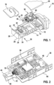
- FIG 1 shows a perspective view of a sensor 10 for determining a parameter of a fluid medium.
- Sensor 10 is designed as a hot-film air mass meter and includes a sensor housing 12 designed as a plug-in sensor, which can be plugged into a flow pipe, in particular an intake tract of an internal combustion engine, for example.
- the sensor housing 12 has a housing body 14 , a measuring channel cover 16 , an electronics compartment 18 and an electronics compartment cover 20 for closing the electronics compartment 18 .
- a channel structure 22 is formed in the housing body 16 .
- the duct structure 22 has a main duct 24, which is located in a main flow outlet 26, for example on the underside 28 in relation to the representation in FIG figure 1 of the sensor housing 12, as well as a bypass or measuring channel 30 branching off from the main channel 24, which opens into a bypass or measuring channel outlet 32, which can be designed separately or integrated.
- a representative quantity of the fluid medium can flow through the channel structure 22 via an inlet opening 34 which, in the inserted state, faces a main flow direction 36 of the fluid medium at the location of the sensor housing 12 .
- FIG 2 shows an enlarged view of an electronic module 38 of sensor 10.
- a sensor carrier 40 protrudes into measuring channel 30.
- a sensor chip 42 is embedded in sensor carrier 40 in such a way that a micromechanical sensor membrane 44 configured as the sensor area of sensor chip 42 protrudes from the fluid medium can flow over.
- the sensor carrier 40 is part of the electronic module 38 with the sensor chip 42.
- the electronic module 38 also has a curved base plate 46 and a plate attached thereto, for example glued on Circuit board 48 with a control and evaluation circuit 50 on.
- the sensor chip 42 is electrically connected to the control and evaluation circuit 50 via electrical connections 52, which are configured here as wire bonding.
- the electronics module 38 created in this way is inserted, for example glued, into the electronics space 18 of the housing body 14--itself an integral part of the sensor housing 12.
- the sensor carrier 40 protrudes into the channel structure 22 .
- the electronics compartment 18 is then closed by the electronics compartment cover 20 .
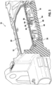
- FIG 3 12 shows a cross-sectional view of a sensor 10 according to a first embodiment of the present invention.
- Electronics compartment cover 20 has at least partially electrically conductive properties.
- the electronics compartment cover 20 is made of an electrically conductive material, such as electrically conductive plastic.
- the electronics module 38 is connected to an interior 54 of the electronics compartment lid 20, as will be described in more detail below.
- the floor panel 46 is thus electrically conductively connected to the interior 54 of the electronics compartment cover 20 .
- This can be implemented, for example, in that the electronics compartment cover 20 has a projection 56 .
- the projection 56 is provided with a hole 58 .
- the hole 58 is conical and tapers in the direction of the electronics compartment cover 20.
- the configuration of the electronics compartment cover 20 with the projection 56 and the hole 58 can be realized, for example, by the electronics compartment cover 20 being made of plastic and the hole 58 being formed as a result that a support pin is introduced into the injection mold around which the plastic is injected.
- the floor panel 46 has a contact pin 60 protruding therefrom.
- the contact pin 60 is arranged at a position of the floor panel 46 which is intended to face the projection 56 .
- the contact pin 60 is also conical, or as a flat cone, namely as part of a metallic stamped part, and tapers in a direction away from the floor panel.
- a diameter of contact pin 60 is greater than or equal to a diameter of hole 58.
- the base plate 46 is connected to the interior 54 of the electronics compartment cover 20 in combination with an at least partial removal of material from the surface 62 of the electronics compartment cover 20 .
- the electronics module 46 is electrically conductively connected to an interior 64 of the projection 56 by means of the contact pin 60 .
- the contact pin 60 is shorter than the projection 56. The contact pin therefore does not penetrate the cover 20 of the electronics compartment.
- the contact pin 60 and the hole 58 can be cylindrical.
- figure 4 12 shows a cross-sectional view of a sensor 10 according to a second embodiment of the present invention. Only the differences from the first embodiment are described below, and the same components are given the same reference symbols.
- the electronics compartment cover 20 has a projection 56 .
- the projection 56 is nose-shaped and, in contrast to the first embodiment, has no hole 58 .
- the floor panel 46 has a groove 66 .
- a width of groove 66 is smaller than or equal to a width of projection 56. In other words, groove 66 is the same width or narrower than projection 56.
- the floor panel 46 scratches the projection 56 on the outside. This results in a partial removal of material from the surface 62 of the electronics compartment cover 20 in the area of the projection 56. This creates contact with the lowest possible contact resistance and the base plate 46 is securely connected to the interior 54 of the electronics compartment cover 20 in an electrically conductive manner.
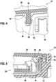
- FIG. 12 shows a cross-sectional view of a sensor 10 according to a third embodiment of the present invention. Only the Described differences from the first embodiment and the same components are provided with the same reference numerals.
- the projection 56 of the electronics compartment cover 20 is wider than in the second embodiment and has a side surface 68 which faces or lies opposite a sharp-edged punched edge 70 of the floor panel 46 in a mounted state.
- material is partially removed from the surface 62 of the electronics compartment cover 20, since the sharp-edged punched edge 70 of the base plate 46 scratches the side surface 68. This brings about a contact with the lowest possible contact resistance and the base plate 46 is securely connected to the interior 54 of the electronics compartment cover 20 in an electrically conductive manner.
- figure 6 12 shows a cross-sectional view of a sensor 10 according to a fourth embodiment of the present invention. Only the differences from the first embodiment are described below, and the same components are given the same reference symbols.
- the protrusion 56 is formed longer than the protrusion 56 of the third embodiment.
- the projection 56 is arranged in such a way that, during assembly, the electronics compartment cover 20 is connected to the punched edge 70 of the floor panel 46 in a resilient manner. In the process, the punching edge 70 is pressed slightly outwards by the projection 56 .
- material is partially removed from the surface 62 of the electronics compartment cover 20, since the sharp-edged punched edge 70 of the base plate 46 scratches the side surface 68.
- the surface of the elastic spring connection of the base plate 46 must be configured locally that material removal can take place on the cover 62 due to a locally increased surface roughness. This brings about a contact with the lowest possible contact resistance and the base plate 46 is securely connected to the interior 54 of the electronics compartment cover 20 in an electrically conductive manner.
- FIG 7 12 shows a side view of electronics module 38 as may be used in any of the previously described embodiments.
- the floor panel 46 is set to a fixed potential 72 .
- Floor panel 46 is connected to the fixed potential 72 by means of an electrically conductive adhesive 74 .
- the fixed electrical potential 72 can be a ground contact 76 of the printed circuit board 48, for example.
- figure 8 12 shows a side view of electronics module 38 as may be used in any of the previously described embodiments.
- the base plate 46 is connected to the fixed potential 72 .
- the bottom plate 46 is connected to the fixed potential 72 by means of wire bonding 78.
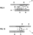
- FIG 9 12 shows a cross-sectional view of a sensor 10 according to a fifth embodiment of the present invention. Only the differences from the first embodiment are described below, and the same components are given the same reference symbols.
- the electronics compartment cover 20 has an insert component 80 made of an electrically conductive material in its interior 54 .
- the insert component 80 is made of metal, for example.
- the insert component 80 is electrically conductively connected to the electronics module 38 .
- the insert component 80 is electrically conductively connected to the electronic module 38 by means of an elastic contact 82, such as a so-called S-spring.
- connection of the insert component 80 to the elastic contact 82 can be realized by connecting them to one another during the manufacture of the electronics compartment cover 20 or by overmolding the insert component 80 and subsequently removing part of the surface 62 so that the elastic contact 82 the insert component 80 can be contacted.
- the elastic contact 82 can be oriented essentially horizontally, i.e. parallel to the electronics compartment cover 20 or the floor panel 46, and can be connected to a stop surface 84 made of an electrically conductive material, which in turn can be connected to the ground contact 76 by means of an electrically conductive adhesive 74 connected is.
- figure 10 12 shows a cross-sectional view of a sensor 10 according to a sixth embodiment of the present invention. Only the differences from the fifth embodiment are described below, and the same components are given the same reference symbols.
- the fifth embodiment is resorted to. The difference is that the elastic contact 82 is oriented vertically, ie perpendicular to the electronics compartment cover 20 or the floor panel 46, and is directly connected to the ground contact 76.
Landscapes
- Physics & Mathematics (AREA)
- Fluid Mechanics (AREA)
- General Physics & Mathematics (AREA)
- Measuring Volume Flow (AREA)
Claims (3)
- Capteur (10) permettant de déterminer au moins un paramètre d'un milieu fluide s'écoulant dans un conduit de mesure (30), en particulier d'un débit massique d'air d'aspiration d'un moteur à combustion interne, dans lequel le capteur (10) présente un boîtier de capteur (12), en particulier une sonde à piquer introduite ou pouvant être introduite dans un tube d'écoulement et dans laquelle est réalisé le conduit de mesure (30), et au moins une puce de capteur (42) disposée dans le conduit de mesure (30) pour déterminer le paramètre du milieu fluide, dans lequel le boîtier de capteur (12) présente un compartiment électronique (18) pour recevoir un module électronique (38) et un couvercle de compartiment électronique (20) pour fermer le compartiment électronique (18), dans lequel le module électronique (38) est introduit dans le compartiment électronique (18), dans lequel le couvercle de compartiment électronique (20) présente au moins en partie des propriétés de conductivité électrique, dans lequel le module électronique (38) est relié de manière électriquement conductrice à un espace intérieur (54) du couvercle de compartiment électronique (20), dans lequel le module électronique (38) présente une tôle de fond (46), dans lequel la tôle de fond (46) est reliée de manière électriquement conductrice à l'espace intérieur (54) du couvercle de compartiment électronique (20),
caractérisé en ce que la tôle de fond (46) est reliée à l'espace intérieur (54) du couvercle de compartiment électronique (20) en combinaison avec un enlèvement de copeaux au moins partiel d'une surface (62) du couvercle de compartiment électronique (20), en ce que- le couvercle de compartiment électronique (20) présente une saillie (56) munie d'un trou (58), et la tôle de fond (46) présente une broche de contact (60), dans lequel le diamètre de la broche de contact (60) est supérieur au diamètre du trou (58), et la broche de contact (60) érafle une peau d'injection ou une surface (62) du couvercle de compartiment électronique (20), ou- le couvercle de compartiment électronique (20) présente une saillie (56), et la tôle de fond (46) présente une rainure à arêtes vives (66), dans lequel une largeur de la rainure (66) est inférieure ou égale à une largeur de la saillie (56) et la saillie (56) est mise en contact dans la rainure (66) au moyen d'un assemblage serré, et la rainure à arêtes vives (66) érafle la saillie (56) à l'extérieur, ou- le couvercle de compartiment électronique (20) présente une saillie (56), et la tôle de fond présente une arête d'estampage à arêtes vives (70), dans lequel l'arête d'estampage à arêtes vives (70) érafle une surface latérale de la saillie (58). - Capteur (10) selon la revendication précédente, dans lequel la tôle de fond (46) est réglée sur un potentiel fixe (72).
- Capteur (10) selon la revendication précédente, dans lequel la tôle de fond (46) est reliée au potentiel fixe (72) au moyen d'une colle électriquement conductrice (74) ou au moyen d'un câble par fil (78).
Applications Claiming Priority (2)
| Application Number | Priority Date | Filing Date | Title |
|---|---|---|---|
| DE102015206677.0A DE102015206677A1 (de) | 2015-04-14 | 2015-04-14 | Sensor zur Bestimmung wenigstens eines Parameters eines durch einen Messkanal strömenden fluiden Mediums |
| PCT/EP2016/053938 WO2016165866A1 (fr) | 2015-04-14 | 2016-02-25 | Capteur pour déterminer au moins un paramètre d'un milieu fluide s'écoulant dans un conduit de mesure |
Publications (2)
| Publication Number | Publication Date |
|---|---|
| EP3283853A1 EP3283853A1 (fr) | 2018-02-21 |
| EP3283853B1 true EP3283853B1 (fr) | 2023-08-02 |
Family
ID=55411402
Family Applications (1)
| Application Number | Title | Priority Date | Filing Date |
|---|---|---|---|
| EP16706205.8A Active EP3283853B1 (fr) | 2015-04-14 | 2016-02-25 | Capteur pour déterminer au moins un paramètre d'un milieu fluide s'écoulant dans un conduit de mesure |
Country Status (5)
| Country | Link |
|---|---|
| US (1) | US10627275B2 (fr) |
| EP (1) | EP3283853B1 (fr) |
| CN (1) | CN107532935B (fr) |
| DE (1) | DE102015206677A1 (fr) |
| WO (1) | WO2016165866A1 (fr) |
Families Citing this family (5)
| Publication number | Priority date | Publication date | Assignee | Title |
|---|---|---|---|---|
| JP2019023606A (ja) * | 2017-07-24 | 2019-02-14 | 株式会社デンソー | 物理量計測装置及び物理量計測装置の製造方法 |
| WO2019225073A1 (fr) * | 2018-05-22 | 2019-11-28 | 日立オートモティブシステムズ株式会社 | Dispositif de détection de quantité physique |
| DE102018215714A1 (de) * | 2018-09-14 | 2020-03-19 | Robert Bosch Gmbh | Sensor zur Bestimmung wenigstens eines Parameters eines durch einen Messkanal strömenden fluiden Mediums |
| DE102018221847A1 (de) * | 2018-12-14 | 2020-06-18 | Robert Bosch Gmbh | Elektrische Vorrichtung mit einem Sensor |
| DE102019126013A1 (de) * | 2019-09-26 | 2021-04-01 | Endress+Hauser Flowtec Ag | Magnetisch-induktives Durchflussmessgerät |
Family Cites Families (14)
| Publication number | Priority date | Publication date | Assignee | Title |
|---|---|---|---|---|
| DE4447570C2 (de) | 1994-07-22 | 1999-06-02 | Bosch Gmbh Robert | Vorrichtung zur Messung der Masse eines strömenden Mediums |
| US6299469B1 (en) | 1999-04-22 | 2001-10-09 | Visteon Global Technologies, Inc. | Flexible circuit board splice clamp |
| DE10036290A1 (de) * | 2000-07-26 | 2002-02-07 | Bosch Gmbh Robert | Vorrichtung zur Bestimmung zumindest eines Parameters eines strömenden Mediums |
| JP3871566B2 (ja) * | 2001-12-26 | 2007-01-24 | シーケーディ株式会社 | 熱式流量計 |
| JP2008182126A (ja) * | 2007-01-25 | 2008-08-07 | Hitachi Ltd | エンジンルーム内に設置される電子機器 |
| DE102008042155A1 (de) * | 2008-09-17 | 2010-03-18 | Robert Bosch Gmbh | Sensoranordnung zur Bestimmung eines Parameters eines fluiden Mediums |
| US8002315B2 (en) | 2009-12-23 | 2011-08-23 | General Electric Corporation | Device for measuring fluid properties in caustic environments |
| DE102010028267A1 (de) * | 2010-04-27 | 2011-10-27 | Robert Bosch Gmbh | Vorrichtung zur Erfassung einer Eigenschaft eines strömenden fluiden Mediums |
| DE102010020264A1 (de) | 2010-05-28 | 2011-12-01 | Continental Automotive Gmbh | Luftmassenmesser |
| DE102010043083A1 (de) * | 2010-10-28 | 2012-05-03 | Robert Bosch Gmbh | Sensorvorrichtung zur Erfassung einer Strömungseigenschaft eines fluiden Mediums |
| US8852123B2 (en) * | 2010-12-30 | 2014-10-07 | Roche Diagnostics Operations, Inc. | Handheld medical diagnostic devices housing with sample transfer |
| CN103501845B (zh) * | 2011-04-28 | 2016-02-10 | 泰尔茂株式会社 | 注射针组装体及药剂注射装置 |
| DE102013212162A1 (de) | 2013-06-26 | 2014-12-31 | Robert Bosch Gmbh | Sensorvorrichtung zur Erfassung wenigstens einer Eigenschaft eines in einem Kanal strömenden fluiden Mediums |
| DE102013215522A1 (de) | 2013-08-07 | 2015-02-12 | Robert Bosch Gmbh | Sensorvorrichtung zur Bestimmung wenigstens eines Parameters eines durch einen Kanal strömenden fluiden Mediums |
-
2015
- 2015-04-14 DE DE102015206677.0A patent/DE102015206677A1/de active Pending
-
2016
- 2016-02-25 WO PCT/EP2016/053938 patent/WO2016165866A1/fr not_active Ceased
- 2016-02-25 EP EP16706205.8A patent/EP3283853B1/fr active Active
- 2016-02-25 US US15/566,119 patent/US10627275B2/en active Active
- 2016-02-25 CN CN201680022265.9A patent/CN107532935B/zh active Active
Also Published As
| Publication number | Publication date |
|---|---|
| CN107532935A (zh) | 2018-01-02 |
| US10627275B2 (en) | 2020-04-21 |
| DE102015206677A1 (de) | 2016-10-20 |
| CN107532935B (zh) | 2020-02-14 |
| US20180087944A1 (en) | 2018-03-29 |
| EP3283853A1 (fr) | 2018-02-21 |
| WO2016165866A1 (fr) | 2016-10-20 |
Similar Documents
| Publication | Publication Date | Title |
|---|---|---|
| EP3283853B1 (fr) | Capteur pour déterminer au moins un paramètre d'un milieu fluide s'écoulant dans un conduit de mesure | |
| EP3230697B1 (fr) | Détecteur pour déterminer au moins un paramètre d'un milieu fluide s'écoulant dans un conduit de mesure | |
| EP3191804B1 (fr) | Dispositif de détection pour déterminer au moins un paramètre d'un milieu fluide s'écoulant dans un conduit de mesure | |
| EP3097388B1 (fr) | Système de détection servant à déterminer au moins un paramètre d'un milieu fluide circulant dans une structure de conduit | |
| EP2686644B1 (fr) | Dispositif servant à appréhender au moins une propriété d'un milieu fluide | |
| DE102014202853A1 (de) | Sensoranordnung zur Bestimmung wenigstens eines Parameters eines durch einen Kanal strömenden fluiden Mediums | |
| DE102008042166A1 (de) | Sensoranordnung zur Bestimmung eines Parameters eines fluiden Mediums | |
| DE102016209150A1 (de) | Sensor zur Bestimmung wenigstens eines Parameters eines durch einen Messkanal strömenden fluiden Mediums | |
| DE102013221791B4 (de) | Sensoranordnung zur Bestimmung wenigstens eines Parameters eines durch einen Kanal strömenden fluiden Mediums | |
| DE102013226345A1 (de) | Sensoranordnung zur Bestimmung wenigstens eines Parameters eines durch einen Kanal strömenden fluiden Mediums | |
| DE102014215209B4 (de) | Sensor zur Bestimmung wenigstens eines Parameters eines durch einen Messkanal strömenden fluiden Mediums | |
| DE102013222051A1 (de) | Drucksensor mit eingebautem Temperatursensor | |
| DE102014218579B4 (de) | Sensoranordnung zur Bestimmung wenigstens eines Parameters eines durch einen Kanal strömenden fluiden Mediums | |
| DE102015206702B4 (de) | Sensor zur Bestimmung wenigstens eines Parameters eines durch einen Kanal strömenden fluiden Mediums | |
| EP3283854B1 (fr) | Capteur pour déterminer au moins un paramètre d'un milieu fluide s'écoulant dans un conduit de mesure | |
| DE102012200151A1 (de) | Sensorvorrichtung zur Bestimmung wenigstens eines Parameters eines durch einen Kanal strömenden fluiden Mediums | |
| DE102019220425A1 (de) | Sensor zur Bestimmung wenigstens eines Parameters eines durch einen Messkanal strömenden fluiden Mediums | |
| DE102012220098B4 (de) | Sensorvorrichtung zur Erfassung mindestens einer Strömungseigenschaft eines fluiden Mediums | |
| DE102012204646A1 (de) | Vorrichtung zur Erfassung eines Drucks und einer Temperatur eines Fluids | |
| EP2525197A1 (fr) | Dispositif destiné à déterminer au moins une propriété d'un milieu de fluide s'écoulant | |
| DE102011078992A1 (de) | Sensoranordnung zur Bestimmung wenigstens einer Strömungseigenschaft eines mit einer Hauptströmungsrichtung strömenden fluiden Mediums | |
| DE102011089483A1 (de) | Sensoranordnung zur Bestimmung wenigstens eines Parameters eines durch einen Kanal strömenden fluiden Mediums | |
| DE102012200147A1 (de) | Sensorvorrichtung zur Bestimmung wenigstens eines Parameters eines durch einen Kanal strömenden fluiden Mediums | |
| DE102014218592B4 (de) | Sensoranordnung zur Bestimmung wenigstens eines Parameters eines durch eine Kanalstruktur strömenden fluiden Mediums | |
| DE102012216511A1 (de) | Sensoranordnung zur Bestimmung wenigstens eines Parameters eines durch einen Kanal strömenden fluiden Mediums |
Legal Events
| Date | Code | Title | Description |
|---|---|---|---|
| STAA | Information on the status of an ep patent application or granted ep patent |
Free format text: STATUS: THE INTERNATIONAL PUBLICATION HAS BEEN MADE |
|
| PUAI | Public reference made under article 153(3) epc to a published international application that has entered the european phase |
Free format text: ORIGINAL CODE: 0009012 |
|
| STAA | Information on the status of an ep patent application or granted ep patent |
Free format text: STATUS: REQUEST FOR EXAMINATION WAS MADE |
|
| 17P | Request for examination filed |
Effective date: 20171114 |
|
| AK | Designated contracting states |
Kind code of ref document: A1 Designated state(s): AL AT BE BG CH CY CZ DE DK EE ES FI FR GB GR HR HU IE IS IT LI LT LU LV MC MK MT NL NO PL PT RO RS SE SI SK SM TR |
|
| AX | Request for extension of the european patent |
Extension state: BA ME |
|
| DAV | Request for validation of the european patent (deleted) | ||
| DAX | Request for extension of the european patent (deleted) | ||
| RAP1 | Party data changed (applicant data changed or rights of an application transferred) |
Owner name: ROBERT BOSCH GMBH |
|
| STAA | Information on the status of an ep patent application or granted ep patent |
Free format text: STATUS: EXAMINATION IS IN PROGRESS |
|
| 17Q | First examination report despatched |
Effective date: 20200514 |
|
| GRAP | Despatch of communication of intention to grant a patent |
Free format text: ORIGINAL CODE: EPIDOSNIGR1 |
|
| STAA | Information on the status of an ep patent application or granted ep patent |
Free format text: STATUS: GRANT OF PATENT IS INTENDED |
|
| INTG | Intention to grant announced |
Effective date: 20230524 |
|
| GRAS | Grant fee paid |
Free format text: ORIGINAL CODE: EPIDOSNIGR3 |
|
| GRAA | (expected) grant |
Free format text: ORIGINAL CODE: 0009210 |
|
| STAA | Information on the status of an ep patent application or granted ep patent |
Free format text: STATUS: THE PATENT HAS BEEN GRANTED |
|
| AK | Designated contracting states |
Kind code of ref document: B1 Designated state(s): AL AT BE BG CH CY CZ DE DK EE ES FI FR GB GR HR HU IE IS IT LI LT LU LV MC MK MT NL NO PL PT RO RS SE SI SK SM TR |
|
| REG | Reference to a national code |
Ref country code: GB Ref legal event code: FG4D Free format text: NOT ENGLISH |
|
| REG | Reference to a national code |
Ref country code: CH Ref legal event code: EP |
|
| REG | Reference to a national code |
Ref country code: DE Ref legal event code: R096 Ref document number: 502016015989 Country of ref document: DE |
|
| REG | Reference to a national code |
Ref country code: IE Ref legal event code: FG4D Free format text: LANGUAGE OF EP DOCUMENT: GERMAN |
|
| REG | Reference to a national code |
Ref country code: LT Ref legal event code: MG9D |
|
| REG | Reference to a national code |
Ref country code: NL Ref legal event code: MP Effective date: 20230802 |
|
| PG25 | Lapsed in a contracting state [announced via postgrant information from national office to epo] |
Ref country code: GR Free format text: LAPSE BECAUSE OF FAILURE TO SUBMIT A TRANSLATION OF THE DESCRIPTION OR TO PAY THE FEE WITHIN THE PRESCRIBED TIME-LIMIT Effective date: 20231103 |
|
| PG25 | Lapsed in a contracting state [announced via postgrant information from national office to epo] |
Ref country code: IS Free format text: LAPSE BECAUSE OF FAILURE TO SUBMIT A TRANSLATION OF THE DESCRIPTION OR TO PAY THE FEE WITHIN THE PRESCRIBED TIME-LIMIT Effective date: 20231202 |
|
| PG25 | Lapsed in a contracting state [announced via postgrant information from national office to epo] |
Ref country code: SE Free format text: LAPSE BECAUSE OF FAILURE TO SUBMIT A TRANSLATION OF THE DESCRIPTION OR TO PAY THE FEE WITHIN THE PRESCRIBED TIME-LIMIT Effective date: 20230802 Ref country code: RS Free format text: LAPSE BECAUSE OF FAILURE TO SUBMIT A TRANSLATION OF THE DESCRIPTION OR TO PAY THE FEE WITHIN THE PRESCRIBED TIME-LIMIT Effective date: 20230802 Ref country code: PT Free format text: LAPSE BECAUSE OF FAILURE TO SUBMIT A TRANSLATION OF THE DESCRIPTION OR TO PAY THE FEE WITHIN THE PRESCRIBED TIME-LIMIT Effective date: 20231204 Ref country code: NO Free format text: LAPSE BECAUSE OF FAILURE TO SUBMIT A TRANSLATION OF THE DESCRIPTION OR TO PAY THE FEE WITHIN THE PRESCRIBED TIME-LIMIT Effective date: 20231102 Ref country code: NL Free format text: LAPSE BECAUSE OF FAILURE TO SUBMIT A TRANSLATION OF THE DESCRIPTION OR TO PAY THE FEE WITHIN THE PRESCRIBED TIME-LIMIT Effective date: 20230802 Ref country code: LV Free format text: LAPSE BECAUSE OF FAILURE TO SUBMIT A TRANSLATION OF THE DESCRIPTION OR TO PAY THE FEE WITHIN THE PRESCRIBED TIME-LIMIT Effective date: 20230802 Ref country code: LT Free format text: LAPSE BECAUSE OF FAILURE TO SUBMIT A TRANSLATION OF THE DESCRIPTION OR TO PAY THE FEE WITHIN THE PRESCRIBED TIME-LIMIT Effective date: 20230802 Ref country code: IS Free format text: LAPSE BECAUSE OF FAILURE TO SUBMIT A TRANSLATION OF THE DESCRIPTION OR TO PAY THE FEE WITHIN THE PRESCRIBED TIME-LIMIT Effective date: 20231202 Ref country code: HR Free format text: LAPSE BECAUSE OF FAILURE TO SUBMIT A TRANSLATION OF THE DESCRIPTION OR TO PAY THE FEE WITHIN THE PRESCRIBED TIME-LIMIT Effective date: 20230802 Ref country code: GR Free format text: LAPSE BECAUSE OF FAILURE TO SUBMIT A TRANSLATION OF THE DESCRIPTION OR TO PAY THE FEE WITHIN THE PRESCRIBED TIME-LIMIT Effective date: 20231103 Ref country code: FI Free format text: LAPSE BECAUSE OF FAILURE TO SUBMIT A TRANSLATION OF THE DESCRIPTION OR TO PAY THE FEE WITHIN THE PRESCRIBED TIME-LIMIT Effective date: 20230802 |
|
| PG25 | Lapsed in a contracting state [announced via postgrant information from national office to epo] |
Ref country code: PL Free format text: LAPSE BECAUSE OF FAILURE TO SUBMIT A TRANSLATION OF THE DESCRIPTION OR TO PAY THE FEE WITHIN THE PRESCRIBED TIME-LIMIT Effective date: 20230802 |
|
| PG25 | Lapsed in a contracting state [announced via postgrant information from national office to epo] |
Ref country code: ES Free format text: LAPSE BECAUSE OF FAILURE TO SUBMIT A TRANSLATION OF THE DESCRIPTION OR TO PAY THE FEE WITHIN THE PRESCRIBED TIME-LIMIT Effective date: 20230802 |
|
| PG25 | Lapsed in a contracting state [announced via postgrant information from national office to epo] |
Ref country code: SM Free format text: LAPSE BECAUSE OF FAILURE TO SUBMIT A TRANSLATION OF THE DESCRIPTION OR TO PAY THE FEE WITHIN THE PRESCRIBED TIME-LIMIT Effective date: 20230802 Ref country code: RO Free format text: LAPSE BECAUSE OF FAILURE TO SUBMIT A TRANSLATION OF THE DESCRIPTION OR TO PAY THE FEE WITHIN THE PRESCRIBED TIME-LIMIT Effective date: 20230802 Ref country code: ES Free format text: LAPSE BECAUSE OF FAILURE TO SUBMIT A TRANSLATION OF THE DESCRIPTION OR TO PAY THE FEE WITHIN THE PRESCRIBED TIME-LIMIT Effective date: 20230802 Ref country code: EE Free format text: LAPSE BECAUSE OF FAILURE TO SUBMIT A TRANSLATION OF THE DESCRIPTION OR TO PAY THE FEE WITHIN THE PRESCRIBED TIME-LIMIT Effective date: 20230802 Ref country code: DK Free format text: LAPSE BECAUSE OF FAILURE TO SUBMIT A TRANSLATION OF THE DESCRIPTION OR TO PAY THE FEE WITHIN THE PRESCRIBED TIME-LIMIT Effective date: 20230802 Ref country code: CZ Free format text: LAPSE BECAUSE OF FAILURE TO SUBMIT A TRANSLATION OF THE DESCRIPTION OR TO PAY THE FEE WITHIN THE PRESCRIBED TIME-LIMIT Effective date: 20230802 Ref country code: SK Free format text: LAPSE BECAUSE OF FAILURE TO SUBMIT A TRANSLATION OF THE DESCRIPTION OR TO PAY THE FEE WITHIN THE PRESCRIBED TIME-LIMIT Effective date: 20230802 |
|
| REG | Reference to a national code |
Ref country code: DE Ref legal event code: R097 Ref document number: 502016015989 Country of ref document: DE |
|
| PLBE | No opposition filed within time limit |
Free format text: ORIGINAL CODE: 0009261 |
|
| STAA | Information on the status of an ep patent application or granted ep patent |
Free format text: STATUS: NO OPPOSITION FILED WITHIN TIME LIMIT |
|
| 26N | No opposition filed |
Effective date: 20240503 |
|
| PG25 | Lapsed in a contracting state [announced via postgrant information from national office to epo] |
Ref country code: SI Free format text: LAPSE BECAUSE OF FAILURE TO SUBMIT A TRANSLATION OF THE DESCRIPTION OR TO PAY THE FEE WITHIN THE PRESCRIBED TIME-LIMIT Effective date: 20230802 |
|
| PG25 | Lapsed in a contracting state [announced via postgrant information from national office to epo] |
Ref country code: MC Free format text: LAPSE BECAUSE OF FAILURE TO SUBMIT A TRANSLATION OF THE DESCRIPTION OR TO PAY THE FEE WITHIN THE PRESCRIBED TIME-LIMIT Effective date: 20230802 |
|
| REG | Reference to a national code |
Ref country code: CH Ref legal event code: PL |
|
| PG25 | Lapsed in a contracting state [announced via postgrant information from national office to epo] |
Ref country code: LU Free format text: LAPSE BECAUSE OF NON-PAYMENT OF DUE FEES Effective date: 20240225 |
|
| PG25 | Lapsed in a contracting state [announced via postgrant information from national office to epo] |
Ref country code: CH Free format text: LAPSE BECAUSE OF NON-PAYMENT OF DUE FEES Effective date: 20240229 |
|
| GBPC | Gb: european patent ceased through non-payment of renewal fee |
Effective date: 20240225 |
|
| PG25 | Lapsed in a contracting state [announced via postgrant information from national office to epo] |
Ref country code: LU Free format text: LAPSE BECAUSE OF NON-PAYMENT OF DUE FEES Effective date: 20240225 Ref country code: CH Free format text: LAPSE BECAUSE OF NON-PAYMENT OF DUE FEES Effective date: 20240229 |
|
| PG25 | Lapsed in a contracting state [announced via postgrant information from national office to epo] |
Ref country code: BG Free format text: LAPSE BECAUSE OF FAILURE TO SUBMIT A TRANSLATION OF THE DESCRIPTION OR TO PAY THE FEE WITHIN THE PRESCRIBED TIME-LIMIT Effective date: 20230802 |
|
| PG25 | Lapsed in a contracting state [announced via postgrant information from national office to epo] |
Ref country code: BG Free format text: LAPSE BECAUSE OF FAILURE TO SUBMIT A TRANSLATION OF THE DESCRIPTION OR TO PAY THE FEE WITHIN THE PRESCRIBED TIME-LIMIT Effective date: 20230802 |
|
| REG | Reference to a national code |
Ref country code: BE Ref legal event code: MM Effective date: 20240229 |
|
| PG25 | Lapsed in a contracting state [announced via postgrant information from national office to epo] |
Ref country code: BE Free format text: LAPSE BECAUSE OF NON-PAYMENT OF DUE FEES Effective date: 20240229 |
|
| PG25 | Lapsed in a contracting state [announced via postgrant information from national office to epo] |
Ref country code: GB Free format text: LAPSE BECAUSE OF NON-PAYMENT OF DUE FEES Effective date: 20240225 |
|
| PG25 | Lapsed in a contracting state [announced via postgrant information from national office to epo] |
Ref country code: IE Free format text: LAPSE BECAUSE OF NON-PAYMENT OF DUE FEES Effective date: 20240225 |
|
| PG25 | Lapsed in a contracting state [announced via postgrant information from national office to epo] |
Ref country code: IE Free format text: LAPSE BECAUSE OF NON-PAYMENT OF DUE FEES Effective date: 20240225 Ref country code: GB Free format text: LAPSE BECAUSE OF NON-PAYMENT OF DUE FEES Effective date: 20240225 Ref country code: BE Free format text: LAPSE BECAUSE OF NON-PAYMENT OF DUE FEES Effective date: 20240229 |
|
| REG | Reference to a national code |
Ref country code: AT Ref legal event code: MM01 Ref document number: 1595276 Country of ref document: AT Kind code of ref document: T Effective date: 20240225 |
|
| PG25 | Lapsed in a contracting state [announced via postgrant information from national office to epo] |
Ref country code: AT Free format text: LAPSE BECAUSE OF NON-PAYMENT OF DUE FEES Effective date: 20240225 |
|
| PGFP | Annual fee paid to national office [announced via postgrant information from national office to epo] |
Ref country code: DE Payment date: 20250422 Year of fee payment: 10 |
|
| PG25 | Lapsed in a contracting state [announced via postgrant information from national office to epo] |
Ref country code: CY Free format text: LAPSE BECAUSE OF FAILURE TO SUBMIT A TRANSLATION OF THE DESCRIPTION OR TO PAY THE FEE WITHIN THE PRESCRIBED TIME-LIMIT; INVALID AB INITIO Effective date: 20160225 |
|
| PG25 | Lapsed in a contracting state [announced via postgrant information from national office to epo] |
Ref country code: HU Free format text: LAPSE BECAUSE OF FAILURE TO SUBMIT A TRANSLATION OF THE DESCRIPTION OR TO PAY THE FEE WITHIN THE PRESCRIBED TIME-LIMIT; INVALID AB INITIO Effective date: 20160225 |
|
| PG25 | Lapsed in a contracting state [announced via postgrant information from national office to epo] |
Ref country code: TR Free format text: LAPSE BECAUSE OF FAILURE TO SUBMIT A TRANSLATION OF THE DESCRIPTION OR TO PAY THE FEE WITHIN THE PRESCRIBED TIME-LIMIT Effective date: 20230802 |
|
| PGFP | Annual fee paid to national office [announced via postgrant information from national office to epo] |
Ref country code: IT Payment date: 20260227 Year of fee payment: 11 |
|
| PGFP | Annual fee paid to national office [announced via postgrant information from national office to epo] |
Ref country code: FR Payment date: 20260223 Year of fee payment: 11 |