EP3284143B1 - Ensemble connecteur électrique scellé - Google Patents
Ensemble connecteur électrique scellé Download PDFInfo
- Publication number
- EP3284143B1 EP3284143B1 EP16780476.4A EP16780476A EP3284143B1 EP 3284143 B1 EP3284143 B1 EP 3284143B1 EP 16780476 A EP16780476 A EP 16780476A EP 3284143 B1 EP3284143 B1 EP 3284143B1
- Authority
- EP
- European Patent Office
- Prior art keywords
- connector body
- wire
- grommet
- axial passage
- rearward
- Prior art date
- Legal status (The legal status is an assumption and is not a legal conclusion. Google has not performed a legal analysis and makes no representation as to the accuracy of the status listed.)
- Active
Links
Images














Classifications
-
- H—ELECTRICITY
- H01—ELECTRIC ELEMENTS
- H01R—ELECTRICALLY-CONDUCTIVE CONNECTIONS; STRUCTURAL ASSOCIATIONS OF A PLURALITY OF MUTUALLY-INSULATED ELECTRICAL CONNECTING ELEMENTS; COUPLING DEVICES; CURRENT COLLECTORS
- H01R13/00—Details of coupling devices of the kinds covered by groups H01R12/70 or H01R24/00 - H01R33/00
- H01R13/46—Bases; Cases
- H01R13/52—Dustproof, splashproof, drip-proof, waterproof, or flameproof cases
- H01R13/5205—Sealing means between cable and housing, e.g. grommet
-
- H—ELECTRICITY
- H01—ELECTRIC ELEMENTS
- H01R—ELECTRICALLY-CONDUCTIVE CONNECTIONS; STRUCTURAL ASSOCIATIONS OF A PLURALITY OF MUTUALLY-INSULATED ELECTRICAL CONNECTING ELEMENTS; COUPLING DEVICES; CURRENT COLLECTORS
- H01R13/00—Details of coupling devices of the kinds covered by groups H01R12/70 or H01R24/00 - H01R33/00
- H01R13/46—Bases; Cases
- H01R13/502—Bases; Cases composed of different pieces
-
- H—ELECTRICITY
- H01—ELECTRIC ELEMENTS
- H01R—ELECTRICALLY-CONDUCTIVE CONNECTIONS; STRUCTURAL ASSOCIATIONS OF A PLURALITY OF MUTUALLY-INSULATED ELECTRICAL CONNECTING ELEMENTS; COUPLING DEVICES; CURRENT COLLECTORS
- H01R13/00—Details of coupling devices of the kinds covered by groups H01R12/70 or H01R24/00 - H01R33/00
- H01R13/46—Bases; Cases
- H01R13/52—Dustproof, splashproof, drip-proof, waterproof, or flameproof cases
- H01R13/5205—Sealing means between cable and housing, e.g. grommet
- H01R13/5208—Sealing means between cable and housing, e.g. grommet having at least two cable receiving openings
-
- H—ELECTRICITY
- H01—ELECTRIC ELEMENTS
- H01R—ELECTRICALLY-CONDUCTIVE CONNECTIONS; STRUCTURAL ASSOCIATIONS OF A PLURALITY OF MUTUALLY-INSULATED ELECTRICAL CONNECTING ELEMENTS; COUPLING DEVICES; CURRENT COLLECTORS
- H01R24/00—Two-part coupling devices, or either of their cooperating parts, characterised by their overall structure
- H01R24/86—Parallel contacts arranged about a common axis
-
- H—ELECTRICITY
- H01—ELECTRIC ELEMENTS
- H01R—ELECTRICALLY-CONDUCTIVE CONNECTIONS; STRUCTURAL ASSOCIATIONS OF A PLURALITY OF MUTUALLY-INSULATED ELECTRICAL CONNECTING ELEMENTS; COUPLING DEVICES; CURRENT COLLECTORS
- H01R43/00—Apparatus or processes specially adapted for manufacturing, assembling, maintaining, or repairing of line connectors or current collectors or for joining electric conductors
- H01R43/005—Apparatus or processes specially adapted for manufacturing, assembling, maintaining, or repairing of line connectors or current collectors or for joining electric conductors for making dustproof, splashproof, drip-proof, waterproof, or flameproof connection, coupling, or casing
-
- H—ELECTRICITY
- H01—ELECTRIC ELEMENTS
- H01R—ELECTRICALLY-CONDUCTIVE CONNECTIONS; STRUCTURAL ASSOCIATIONS OF A PLURALITY OF MUTUALLY-INSULATED ELECTRICAL CONNECTING ELEMENTS; COUPLING DEVICES; CURRENT COLLECTORS
- H01R9/00—Structural associations of a plurality of mutually-insulated electrical connecting elements, e.g. terminal strips or terminal blocks; Terminals or binding posts mounted upon a base or in a case; Bases therefor
- H01R9/16—Fastening of connecting parts to base or case; Insulating connecting parts from base or case
- H01R9/18—Fastening by means of screw or nut
-
- H—ELECTRICITY
- H01—ELECTRIC ELEMENTS
- H01R—ELECTRICALLY-CONDUCTIVE CONNECTIONS; STRUCTURAL ASSOCIATIONS OF A PLURALITY OF MUTUALLY-INSULATED ELECTRICAL CONNECTING ELEMENTS; COUPLING DEVICES; CURRENT COLLECTORS
- H01R2107/00—Four or more poles
-
- H—ELECTRICITY
- H01—ELECTRIC ELEMENTS
- H01R—ELECTRICALLY-CONDUCTIVE CONNECTIONS; STRUCTURAL ASSOCIATIONS OF A PLURALITY OF MUTUALLY-INSULATED ELECTRICAL CONNECTING ELEMENTS; COUPLING DEVICES; CURRENT COLLECTORS
- H01R2201/00—Connectors or connections adapted for particular applications
- H01R2201/26—Connectors or connections adapted for particular applications for vehicles
Definitions
- the field of the present invention relates to electrical connector assemblies.
- examples of sealed electrical connector assemblies that each include a radially compressed wire grommet are disclosed herein.
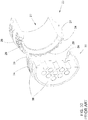
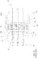
- FIGs. 28-34 An example of a conventional connector assembly (arranged according to an SAE AS50151 standard in the example shown) is shown in Figs. 28-34 and comprises a substantially rigid front connector body 30; a substantially rigid rear connector body 20; a resiliently deformable wire grommet 10; and a threaded nut 40.
- the rear connector body 20 also referred to as a connector accessory or as a connector backshell
- the front connector body 30 also referred to as a plug connector body in a plug-type connector assembly, or as a receptacle connector body in a receptacle-type connector assembly
- a resiliently deformable wire grommet 10 is positioned within the front axial passage and the wires 90 pass through the rear axial passage 22 and through corresponding wire passages 12 of the grommet 10.
- An insulating body 38 of the front connector body 30 is structurally arranged so as to hold one or more electrical contacts 92 that are each connected to a corresponding wire 90.
- the electrical contacts 92 are pin contacts; in other examples the contacts are socket contacts.
- the wire grommet 10 serves to isolate the electrical contacts 92 and the conductive cores of the wires 90 from a use environment.
- the front connector body 30 of the conventional connector assembly has triangular teeth 39 arranged just outside the rear end of the front axial passage; the rear connector body 20 of the conventional connector assembly has mating triangular teeth 29 arranged around the front end of the rear axial passage 22.
- the rear connector body 20 of the conventional connector assembly also can have a so-called web 29w between the teeth 29 but not extending beyond the tips of the teeth 29.
- the teeth 29 and 39 engage one another when the front connector body 30 and the rear connector body are assembled, but no portion of the teeth 29, the web 29w, or the connector body 29 extends forward into the interior of the front connector body 30 ( i.e., forward beyond base portions of the teeth 39).
- the nut 40 includes a central opening and internal threads 44.
- the nut 40 is structurally arranged so as to receive through the central opening a rearward portion of the rear connector body 20 and to obstruct rearward movement of the forward portion of the rear connector body 20 through the central opening.
- an outward circumferential flange 28 of the rear connector body 20 is too large to pass an inward circumferential flange 46 of the nut 40.
- a rearward portion of the front connector body 30 includes external threads 34 that engage the internal threads 44 of the nut 40.
- Tightening of the nut 40 threadedly engaged on the rearward portion of the front connector body 30 results in forward movement of the nut 40 and the rear connector body 20 toward the front connector body 30; fully tightening the nut 40 results in fully engaged assembly of the connector bodies 30 and 20 and engagement of the teeth 29 and 39.
- the wire grommet 10 has a substantially cylindrical outer surface and one or more axial wire passages 12 therethrough.
- Each wire passage 12 includes two or more wire-sealing segments 12a (also referred to as glands) and an intervening, transversely enlarged, internal chamber 12b between each adjacent pair of wire-sealing segments 12a along each wire passage 12.
- Each wire-sealing segment 12a is sized and shaped so as to (i) enable a corresponding wire 90 to be inserted through the corresponding wire passage 12 and (ii) form a seal around the corresponding inserted wire 90.
- a rear portion of the wire grommet 10 extends rearward beyond the rear end of the front connector body 30 and is received within a rearward-tapered forward segment 24 of the rear axial passage 22.
- GB 721,872 A discloses a connector assembly according to the preamble of claim 1.
- An inventive connector assembly comprises a substantially rigid front connector body, a substantially rigid rear connector body, a resiliently deformable wire grommet, and a threaded nut.
- the resiliently deformable wire grommet has a substantially cylindrical outer surface and one or more axial wire passages therethrough.
- Each wire passage includes two or more wire-sealing segments; each wire-sealing segment is sized and shaped so as to (i) enable a corresponding wire to be inserted through the corresponding wire passage and (ii) form a seal around the corresponding inserted wire.
- the front connector body has a front axial passage. A rearward portion of the front connector body includes external threads.
- a forward portion of the front connector body is structurally arranged so as to hold one or more electrical contacts that are each connected to a corresponding wire passing through the rear axial passage and the corresponding wire passage of the grommet.
- At least portions, including a rearward portion, of the front axial passage are structurally arranged so as to receive therein the grommet without substantial radial compression of the grommet.
- the rear connector body has a rear axial passage therethrough.
- a front end of the rear axial passage is large enough to receive therein a rearward portion of the grommet without substantial radial compression of the grommet.
- a rearward-tapered segment of the rear axial passage is structurally arranged so as to receive therein the rearward portion of the grommet, engage the outer surface of the rearward portion of the grommet, and compress radially the rearward portion of the grommet and one or more of the wire-sealing segments of each wire passage therein.
- a forward portion of the rear connector body including at least a portion of the tapered segment of the rear axial passage, is structurally arranged to extend into and fit within the rearward portion of the front axial passage, interposed between the rearward portion of the grommet and an inner surface of the rearward portion of the front axial passage.
- the nut has a central opening and internal threads.
- the nut is structurally arranged so as to (i) receive through the central opening a rearward portion of the rear connector body, (ii) obstruct rearward movement of the forward portion of the rear connector body through the central opening, and (iii) engage with the internal threads the external threads of the front connector body.
- the forward portion of the rear connector body and the rearward portion of the front connector body are structurally adapted so as to effect non-rotatable engagement of the front and rear connector bodies.
- the connector assembly is structurally arranged so that tightening of the nut threadedly engaged on the rearward portion of the front connector body results in forward movement of the nut and the rear connector body toward the front connector body, forward movement of the forward portion of the rear connector body into the rearward portion of the front axial passage, rearward movement of the rearward portion of the grommet into the tapered segment of the rear axial passage, and radial compression, by the tapered segment of the rear axial passage, of the rearward portion of the grommet and one or more of the wire-sealing segments of each wire passage therein.
- a method employing the inventive connector assembly comprises: (a) inserting each one of a set of one or more wires through the wire grommet through a corresponding one of the one or more wire passages; (b) securing one or more corresponding electrical contacts, connected to the forward ends of the wires, to be held by the forward portion of the front connector body; (c) inserting the grommet into the front axial passage; (d) engaging the front and rear connector bodies; (e) threadedly engaging the nut and the front connector body; and (f) tightening of the nut threadedly engaged on the rearward portion of the front connector body, thereby resulting in forward movement of the nut and the rear connector body toward the front connector body, forward movement of the forward portion of the rear connector body into the rearward portion of the front axial passage, rearward movement of the rearward portion of the grommet into the tapered segment of the rear axial passage, and radial compression, by the tapered segment of the rear axial passage, of the rearward portion of the grommet
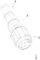
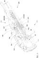
- FIG. 1-7 A first example of an inventive connector assembly is shown in Figs. 1-7 and comprises a substantially rigid front connector body 300 ( Figs. 8A-8C ); a substantially rigid rear connector body 200 ( Figs. 9A-9C ); a resiliently deformable wire grommet 100 ( Figs. 10A and 10B ); and a threaded nut 400 ( Figs. 11A and 11B ).
- the front connector body 300, the rear connector body 200, and the nut 400 can each comprise any one or more suitably rigid solid materials, including but not limited to: one or more metals or metal alloys; one or more plastics, resins, or polymers; one or more natural or synthetic fibrous materials; one or more other electrically conductive materials; or one or more other electrically insulating materials.
- directional terms such a front, forward , rear, rearward, and so forth are defined relative to the connector assembly, with “front” and the like being the direction from the connector assembly toward a mating connector assembly, and “rear” and the like being the opposite direction, i.e., toward one or more wires or a cable connected to the connector assembly.
- Any motion or movement recited in the disclosure, examples, or claims are relative motions or movements, e.g., forward movement of the rear connector body 200 toward the front connector body 300 is equivalent to rearward movement of the front connector body 300 toward the rear connector body 200.
- the substantially rigid rear connector body 200 (also referred to as a connector accessory or as a connector backshell) has a rear axial passage 202 therethrough;
- the substantially rigid front connector body 300 (also referred to as a plug connector body in a plug-type connector assembly, or as a receptacle connector body in a receptacle-type connector assembly) has a front axial passage 302.
- the front connector body 300 is arranged in compliance with a MIL-DTL-38999 standard; any other suitable arrangement of the front connector body 300 can be employed, e.g., a front connector body arranged in compliance with an SAE AS50151 standard.
- inventive apparatus and methods disclosed or claimed herein can be implemented in a variety of connector types or arrangements, those inventive apparatus and methods may be particularly applicable when implemented with front connector bodies compliant with a MIL-DTL-38999 specification or an SAE AS50151 standard.
- the current versions of those specifications and standards are MIL-DTL-38999M dated 11 FEB 2015 and SAE AS50151B dated 28 MAY 2013.
- a resiliently deformable wire grommet 100 is positioned within the front axial passage 302 and the wires 90 pass through the rear axial passage 202 and through corresponding wire passages 102 of the grommet 100.
- a forward portion of the front connector body 300 is structurally arranged so as to hold one or more electrical contacts 92 that are each connected to a corresponding wire 90.
- the electrical contacts 92 are pin contacts; in other examples the contacts are socket contacts. Any suitable number (one through 128 or more), type (e.g., pin or socket), or arrangement ( e.g., square, rectangular, polygonal, or circular array or arrangement) of the one or more electrical contacts 92 can be employed in any type of connector assembly ( e.g., plug, receptacle, bulkhead-mounted, wall-mounted, or cable-mounted).
- the wire grommet 100 serves to isolate the electrical contacts 92 and the conductive cores of the wires 90 from a use environment.
- the rear connector body 200 comprises a metal or metal alloy, so that the rear connector body 200 is electrically conducting and can serve to at least partly electromagnetically shield the one or more wires 90 passing through the rear axial passage 202. If the wires 90 are contained within a sheath (not shown) rearward of the connector assembly, that sheath can continue around a rearward portion of the rear connector body, if needed or desired.
- such a sheath can include conductive sheathing that serves as electromagnetic shielding for the wires 90, and electrical continuity can be established between such conductive sheathing and a conductive rear connector body 200 ( e.g., by banding or crimping the conductive sheath onto the rear connector body 200).
- the sheath can include an outer insulating layer that continues around a rearward portion of the rear connector body 200 (e.g., plastic or elastomeric shrink tubing applied around the wires 90 and the rear connector body 200).
- the front connector body 300 includes one or more metals or metal alloys, which can serve as electrical shielding in a manner similar to that described for the rear connector body 200, particularly if both front and rear connector bodies 300 and 200 include one or more metals or metal alloys and are in electrical contact with one another.
- the front connector body typically also includes one or more insulating materials arranged for holding the electrical contacts 92 in place without introducing unwanted electrical contact between them ( i.e., without shorting them).
- the front connector body 300 includes an insulating body 308 (comprising, e.g., thermoplastic or other suitable insulating material) with wire channels 310 therethrough.
- Each wire channel 310 accommodates a corresponding one of the wires 90 and has a corresponding one of the electrical contacts 92 held at its front end. Additional structural members 312 can be employed to hold the electrical contacts 92 in place if needed or desired.
- a front end of the front connector body 300 can be structurally adapted in any suitable way to engage a mating connector assembly.
- the front connector body 300 includes threads or other mating hardware 314 for engaging a corresponding portion of a mating connector (not shown).
- a forward portion 207 of the front connector body 200 is received in a rearward portion of the interior of the front axial passage 302.
- the forward portion 207 extends forward beyond the tips of the teeth 209 so as to extend forward beyond the base portions of the teeth 309 when the front and rear connector bodies 300 and 200 are assembled with their respective teeth 309 and 209 engaged.
- engagement of the teeth 209 and 309 (triangular in this example; other suitable shapes can be employed) effects non-rotatable engagement of the front and rear connector bodies 300 and 200.
- some other examples e.g., as in the examples of Figs.
- the outer surface of the forward portion of the rear connector body 200 can include a set of one or more longitudinal splines, keys, or grooves
- the inner surface of the rearward portion of the front axial passage 302 can include a set of one or more longitudinal splines, keys, or grooves
- engagement of the splines, keys, or grooves of the front and rear connector bodies 300 and 200 effects the non-rotatable engagement.
- Non-rotatable engagement prevents twisting of the wire grommet 100 or wires 90 by relative rotation of the connector bodies 300 and 200 ( e.g., induced by tightening the threaded nut 400; discussed further below).
- non-rotatable shall include arrangements wherein only limited or constrained relative rotation, or no rotation, of the front and rear connector bodies 300 and 200 might occur. For example, initial engagement of the triangular teeth 209 and 309 still permits limited relative rotation, but it is not until the teeth are fully engaged ( i.e., "bottomed out") that relative rotation is substantially prevented. Both initial and full engagement of the teeth 209 and 309 are encompassed by the term “non-rotatable engagement.”
- the nut 400 includes a central opening 402 and internal threads 404.
- the nut 400 is structurally arranged so as to receive through the central opening 402 a rearward portion of the rear connector body 200 and to obstruct rearward movement of the forward portion of the rear connector body 200 through the central opening 402.
- an outward circumferential flange 208 of the rear connector body 200 is too large to pass an inward circumferential flange 406 of the nut 400; other suitable structural arrangements can be employed.
- a rearward portion of the front connector body 300 includes external threads 304 that engage the internal threads 404 of the nut 400.
- Tightening of the nut 400 threadedly engaged on the rearward portion of the front connector body 300 results in forward movement of the nut 400 and the rear connector body 200 toward the front connector body 300 and concomitant forward movement of the forward portion 207 of the rear connector body 200 into the rearward portion of the front axial passage 302.
- Fully tightening the nut 400 results in fully engaged assembly of the connector bodies 300 and 200 at the forward limit of forward movement of the rear connector body 200 and the nut 400 ( e.g., with the teeth 209 and 309 engaged in the example shown in Figs. 1-7 ).
- contact between the flange 208 of the rear connector body 200 and a rear end of the front connector body 300 limits the forward movement.
- the resiliently deformable (i.e., elastically deformable) wire grommet 100 has a substantially cylindrical outer surface and one or more axial wire passages 102 therethrough.
- Each wire passage 102 includes two or more wire-sealing segments 102a (also referred to as glands).
- Each wire passage 102 typically also includes an intervening, transversely enlarged, internal chamber 102b between each adjacent pair of wire-sealing segments 102a along each wire passage 102; such enlarged chambers 102b can facilitate insertion of the wires 90 through the corresponding passages 102 ( e.g., by providing space to accommodate displacement of compressed grommet material from adjacent wire-sealing segments 102a) without unduly compromising the sealing of each wire 90 by the corresponding passage 102.
- Each wire-sealing segment 102a is sized and shaped so as to (i) enable a corresponding wire 90 to be inserted through the corresponding wire passage 102 and (ii) form a seal around the corresponding inserted wire 90.
- each wire-sealing segment 102a is made slightly smaller than the thickness of the wire 90. Resilient stretching of each wire-sealing segment 102a enables the slightly over-sized wire 90 (and in some examples a wire-containing tube of an insertion/removal tool) to be inserted through the passage 102; resilient rebound of each wire-sealing segment 102a creates seal around the corresponding wire 90.
- wire-sealing segments can vary and typically is determined by the properties of the resilient grommet material, the surface characteristics of the wire insulation, the cross-sectional shapes of the wires 90 and the wire-sealing segments 102a (see below), the size of a wire-containing tube of an insertion/removal tool (if employed), the amount of radial compression of the wire grommet by the rear connector body (discussed further below), and the tightness of the seal needed or desired in a given use environment ( i.e., to achieve operationally acceptable sealing). Any suitable size differential can be employed that enables insertion of the wires 90 through the wire passages 102 and also results in an operationally acceptable seal around the wires 90.
- Typical resiliently deformable materials for wire grommet 100 include, but are not limited to: synthetic or natural rubber; silicone or fluorosilicone elastomer; fluorocarbon elastomer (e.g., Viton®); ethylene propylene diene monomer (EPDM) elastomer; neoprene; other resiliently deformable polymer or resin; or other suitable resiliently deformable material.
- synthetic or natural rubber silicone or fluorosilicone elastomer
- fluorocarbon elastomer e.g., Viton®
- EPDM ethylene propylene diene monomer
- neoprene other resiliently deformable polymer or resin
- suitable resiliently deformable material include, but are not limited to: synthetic or natural rubber; silicone or fluorosilicone elastomer; fluorocarbon elastomer (e.g., Viton®); ethylene propylene diene monomer (EPDM) elasto
- the grommet 100 or the front axial passage 302 can further include a rotational indexing structure (e.g., one or more mating longitudinal grooves, keys, or splines) arranged to permit insertion of the grommet 100 into the front axial passage 302 in only one relative orientation about a longitudinal axis.
- a rotational indexing structure e.g., one or more mating longitudinal grooves, keys, or splines
- the wires 90 passing through the passages 102 and corresponding passages through the insulating body 308 effects rotational alignment of the wire grommet 100 within the front axial passage 302 of the front connector body 300.
- the grommet 100 can be attached or secured to the front connector body 300 within the front axial passage 302, e.g., by adhesive or a mechanical retaining member such as a snap ring or threaded retaining ring. In other examples, the grommet 100 is not secured or attached to the front connector body 300, but is held in place by the engagement of the front and rear connector bodies 300 and 200 with each other.
- each wire-sealing segment 102a has a substantially circular cross section to accommodate a corresponding wire also having a circular cross section.
- a circular cross section for the wire-sealing segments 102a can be employed in some example embodiments with non-circular wires 90 (e.g., oval or elliptical cross sections), so as to eliminate the need to rotationally orient the non-circular wire 90 before inserting it into the corresponding wire passage 102.
- non-circular wire-sealing segments 102a can be employed having a shape corresponding to a non-circular shape of the wires 90, with the wires 90 being properly oriented before insertion through the wire passages 102.
- resiliency of the grommet 100 and the size or shape differential between the wire-sealing segments 102a and the wires 90 may not result in a sufficiently good seal around the wires 90.
- Such instances can arise more frequently when non-circular wires 90 are employed with a grommet 100 having substantially circular wire-sealing segments 102a of the wire passages 102.
- Oval or elliptical wire cross sections arising from current wire manufacturing processes are increasingly common. Poor sealing can also arise with wires have insulation in the form of a spiral-wound tape, which results in a spiral ridge on the outer surface of the wire where each turn of the insulating tape overlaps an adjacent turn. That ridge can provide a path for moisture or other contaminants to enter the connector. It therefore would be desirable to provide enhanced sealing of the wires 90 by the grommet 100.
- the rear connector body 200 is structurally adapted so as to provide, upon fully engaged assembly of the connector assembly, radial compression, within the interior of the front axial passage 302 of the front connector body 300, of the wire grommet 100 over a portion of its length, including radial compression of one or more of the wire-sealing segments 102a.
- the front connector body 300 can also be so adapted in some instances, but in many instances the front connector body 300 is of a conventional arrangement ( e.g., arranged in compliance with a MIL-DTL-38999 specification or an SAE AS50151 standard), with the inventive features of the connector assembly residing primarily in the arrangement of the rear connector body 200.
- both connector bodies 200 and 300 can be provided by the same manufacture or by different manufacturers; in the latter instances (i.e., a conventional front connector body 300 paired with an inventive rear connector body 200) the front and rear connector bodies 300 and 200 may often be provided by different manufacturers.
- both the front and rear connector bodies 300 and 200 are structurally adapted so as to provide, upon fully engaged assembly of the connector assembly, radial compression of the wire grommet 100 over a portion of its length that includes two or more of the wire-sealing segments 102a of each wire passage 102. In each of the examples disclosed herein, it is the radial compression, particularly of at least one wire-sealing segments 102a ( Figs.
- the front end of the rear axial passage 202 is large enough to receive therein a rearward portion of the grommet 100 without substantial radial compression of the grommet 100, and the rear axial passage 202 includes a rearward-tapered segment 204 (referred to hereafter as the tapered segment 204).
- the tapered segment 204 of the rear axial passage 202 is structurally arranged so as to receive therein the rearward portion of the grommet 100, engage its outer surface, and compress it radially along with radially compressing one or more of the wire-sealing segments 102a of each wire passage 102 within the grommet 100.
- At least portions, including a rearward portion, of the front axial passage 302 are structurally arranged so as to receive therein at least the forward portion of the grommet 100 without substantial radial compression of the grommet 100.
- the forward portion 207 of the rear connector body 200 including at least a portion of the tapered segment 204 of the rear axial passage 202, is structurally arranged to extend into and fit within the rearward portion of the front axial passage 302, interposed between the rearward portion of the grommet 100 and an inner surface of the rearward portion of the front axial passage 302.
- An inventive connector assembly arranged according to the present disclosure or appended claims is thus structurally arranged so that tightening the nut 400 drives forward portion 207 and the tapered segment 204 of the axial passage 202 forward into the rearward portion of the front axial passage 302 wedged between the inner surface of the front axial passage 302 and the outer surface of the grommet 100.
- the wedge action of the tapered segment 204 on the outer surface of the grommet 100 results in radial compression of the rearward portion of the grommet 100 and one or more of the wire-sealing segments 102a of each wire passage 102 therein.
- some examples e.g., the examples shown in Figs.
- two or three or more wire-sealing segments can be radially compressed by the wedge action, on the outer surface of the grommet 100, of the tapered segment 204 of the rear axial passage 202.
- the non-rotatable engagement of the front and rear connector bodies 300 and 200 reduces or prevents torsional strain or twisting of the wire grommet 100 by the engaged tapered segment 204 as the rear connector body 200 is driven forward by tightening the nut 400.
- twisting or torsional strain can result in various undesirable effects, such as excessive resistance to tightening the nut 400, disruption of the sealing of the wire-sealing segments 102a around the wires 90, twisting or breakage of the wires 90, or structural failure of the wire grommet 100.
- the grommet 100 comprises a resiliently deformable material to enable radial compression by the tapered segment 204 of the rear axial passage 202.
- resilient materials are not necessarily particularly compressible; radial compression of the rearward portion of the grommet 100 typically causes a portion of the grommet 100 forward of the compressed portion to bulge outward, i.e., to expand radially.
- a forward portion of the tapered segment 204 of the rear axial passage 202 can be structurally arranged so as to accommodate that radial expansion, e.g., by having a radius at its forward end that is larger than the radius of the grommet 100 in its uncompressed state.
- a gap remains at a front end of the rear connector body 200 that can accommodate the radial expansion of that portion of the grommet 100 forward of the radially compressed rearward portion of the grommet 100.
- a resilient sealant 330 can partly fill the gap.
- the connector assembly further comprises a resilient O-ring (e.g., as in Figs. 23-25 , implemented in an example similar to Figs. 12-18 ; also can be implemented in other example arrangements, such as the arrangement shown in Figs. 1-7 ).
- a resilient O-ring e.g., as in Figs. 23-25 , implemented in an example similar to Figs. 12-18 ; also can be implemented in other example arrangements, such as the arrangement shown in Figs. 1-7 ).
- the seal provided by the O-ring is in addition to that provided by the grommet 100 and its radial compression by the tapered segment 204 of the rear axial passage 202.
- the splines typically are arranged or positioned so as not to interfere with sealing provided by the O-ring 340.
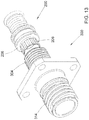
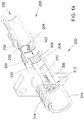
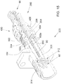
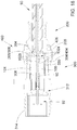
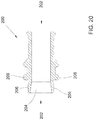
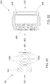
- a second example of a connector assembly is shown in Figs. 12-18 and comprises a substantially rigid front connector body 300 ( Fig. 19 ); a substantially rigid rear connector body 200 ( Fig. 20 ); a resiliently deformable wire grommet 100 ( Fig. 21 ); and a threaded nut 400 ( Fig. 22 ).
- the front connector body 300, the rear connector body 200, and the nut 400 can each comprise any one or more suitably rigid solid materials, including but not limited to: one or more metals or metal alloys; one or more plastics, resins, or polymers; one or more natural or synthetic fibrous materials; one or more other electrically conductive materials; or one or more other electrical insulating materials.
- a forward portion of the front connector body 200 is received in a rearward portion of the front axial passage 302.
- An outer surface of the forward portion of the rear connector body 200 and the inner surface of the rearward portion of the front axial passage 302 are structurally adapted so as to effect non-rotatable and longitudinally movable engagement of the front and rear connector bodies 300 and 200.
- the outer surface of the forward portion of the rear connector body 200 can include a set of one or more longitudinal splines, keys, or grooves
- the inner surface of the rearward portion of the front axial passage 302 can include a set of one or more longitudinal splines, keys, or grooves
- engagement of the splines, keys, or grooves of the front and rear connector bodies 300 and 200 effects the non-rotatable and longitudinally movable engagement.
- the outer surface of the forward portion of the rear connector body 200 includes a set of multiple radially outward-extending longitudinal splines 206
- the inner surface of the rearward portion of the front axial passage 302 includes a set of multiple radially inward-extending longitudinal splines 306, and engagement of the splines 306 and 206 of the front and rear connector bodies 300 and 200, respectively, effects the non-rotatable and longitudinally movable engagement.
- the connector assembly is structurally arranged so as to enable the non-rotatable and longitudinally movable engagement of the front and rear connector bodies 300 and 200 without threaded engagement of the nut 400 and the front connector body 300; once the connector bodies 300 and 200 are engaged, the rear connector body 200 can be moved forward until the threads 404 of the nut 400 can engage the threads 304 of the front connector body 300.
- the front end of the rear axial passage 202 is large enough to receive therein a rearward portion of the grommet 100 without substantial radial compression of the grommet 100, and the rear axial passage 202 includes a rearward-tapered segment 204.
- the tapered segment 204 of the rear axial passage 202 is structurally arranged so as to receive therein the rearward portion of the grommet 100, engage its outer surface, and compress it radially along with radially compressing two or more of the wire-sealing segments 102a of each wire passage 102 within the grommet 100.
- At least portions, including a rearward portion, of the front axial passage 302 are structurally arranged so as to receive therein at least the forward portion of the grommet 100 without substantial radial compression of the grommet 100.
- the rearward portion of the front axial passage 302 is structurally arranged to receive therein a forward portion of the rear connector body 200, including the tapered segment 204 of the rear axial passage 202, interposed between the rearward portion of the grommet 100 and an inner surface of the rearward portion of the front axial passage 302.
- the connector assembly is thus structurally arranged so that tightening the nut 400 drives the tapered segment 204 of the axial passage 202 forward into the rearward portion of the front axial passage 302 wedged between inner surface of the front axial passage 302 and the outer surface of the grommet 100.
- the wedge action of the tapered segment 204 on the outer surface of the grommet 100 results in radial compression of the rearward portion of the grommet 100 and two or more of the wire-sealing segments 102a of each wire passage 102 therein.
- three or more wire-sealing segments can be radially compressed by the wedge action, on the outer surface of the grommet 100, of the tapered segment 204 of the rear axial passage 202.
- the non-rotatable engagement of the front and rear connector bodies 300 and 200 prevents torsional strain or twisting of the wire grommet 100 by the engaged tapered segment 204 as the rear connector body 200 is driven forward by tightening the nut 400.
- Such twisting or torsional strain can result in various undesirable effects, such as excessive resistance to tightening the nut 400, disruption of the sealing of the wire-sealing segments 102a around the wires 90, twisting or breakage of the wires 90, or structural failure of the wire grommet 100.
- a method employing an inventive connector assembly comprises: (a) inserting each one of a set of one or more wires 90 through the wire grommet 100 through a corresponding one of the one or more wire passages 102; (b) securing one or more corresponding electrical contacts 92, connected to the forward ends of the wires 90, to be held by the forward portion of the front connector body 300; (c) inserting the grommet 100 into the front axial passage 302; (d) engaging the front and rear connector bodies 300 and 200; (e) threadedly engaging the nut 400 and the front connector body 300; (f) tightening of the nut 400 threadedly engaged on the rearward portion of the front connector body 300, thereby resulting in forward movement of the nut 400 and the rear connector body 200 toward the front connector body 300, forward movement of the non-rotatably engaged forward portion of the rear connector body 200 into the rearward portion of the front axial passage 302, rearward movement
- the contacts 92 are connected to the wires 90 before the wires 90 are inserted through the wire grommet 100; typically, but not necessarily, the contacts 92 are connected to the wires 90 before the contacts 92 are secured to be held by the front connector body 300.
- the one or more wires 90 are inserted through the wire grommet 100 before inserting the wire grommet 100 into the front axial passage 302.
- the wires 90 serve to align the wire passages 102 with corresponding wire passages in the front connector body 300.
- the one or more wires 90 are inserted through the wire grommet 100 after inserting the wire grommet 100 into the front axial passage 302.
- an insertion/removal tool that comprises a tube arranged (i) to receive therein one of the one or more wires 90, (ii) to be inserted along with the wire 90 through the corresponding one of the one or more wire passages 102, and (iii) to be withdrawn from the corresponding wire passage 102 leaving the wire 90 within the corresponding wire passage 102.
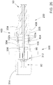
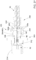
- FIGs. 26 and 27 Another example embodiment is shown in Figs. 26 and 27 wherein a rearward portion of the grommet 100, including at least two of the wire-sealing segments 102a of each wire passage 102, protrudes rearward from the front axial passage 302.
- the tapered segment 204 engages the outer surface of the protruding portion of the grommet 100 and, as the rear connector body 200 is driven forward by tightening the nut 400, compresses the grommet 100 radially, including two or more of the wire-sealing segments 102a of each wire passage 102 therein.
- the connector assembly can be structurally arranged so that the tapered segment 204 of the rear axial passage 202 does not enter the front axial passage 302 as the nut 400 is tightened and the nut 400 and the rear connector body 200 move forward.
- the connector assembly can be structurally arranged so that the forward movement of the nut 400 and the rear connector body 200 toward the front connector body 300 results in at least partial entry of a forward portion of the rear connector body 200 and the tapered segment 204 of the rear axial passage 202 into the front axial passage 302.
- a method employing an inventive connector assembly comprises: (a) inserting each one of a set of one or more wires 90 through the wire grommet 100 through a corresponding one of the one or more wire passages 102; (b) securing one or more corresponding electrical contacts 92, connected to the forward ends of the wires 90, to be held by the forward portion of the front connector body 300; (c) inserting the grommet 100 into the front axial passage 302, leaving a portion of the grommet 100 protruding from the front axial passage 302 rearward beyond a rear end of the front connector body 300; (d) threadedly engaging the nut 400 and the front connector body 300; and (e) tightening of the nut 400 threadedly engaged on the rearward portion of the front connector body 300, thereby resulting in forward movement of the nut 400 and the rear connector body 200 toward the front connector body 300, rearward movement of the protruding portion of the gr
- the protruding portion of the grommet 100 is inserted into the tapered segment 204 of the rear axial passage 202, and the rear connector body advanced somewhat toward the front connector body 300, before the threads 304/404 are engaged.
- the wires 90 can be inserted through the grommet 100 before insertion of the grommet 100 into the front axial passage 302, or, using an insertion/removal tool, after insertion of the grommet 100 into the front axial passage 302.
- each such phrase shall denote the case wherein the quantity in question has been reduced or diminished to such an extent that, for practical purposes in the context of the intended operation or use of the disclosed or claimed apparatus or method, the overall behavior or performance of the apparatus or method does not differ from that which would have occurred had the null quantity in fact been completely removed, exactly equal to zero, or otherwise exactly nulled.
- any labelling of elements, steps, limitations, or other portions of a claim e.g., first, second, etc., (a), (b), (c), etc., or (i), (ii), (iii), etc.) is only for purposes of clarity, and shall not be construed as implying any sort of ordering or precedence of the claim portions so labelled. If any such ordering or precedence is intended, it will be explicitly recited in the claim or, in some instances, it will be implicit or inherent based on the specific content of the claim.
- the provisions of 35 USC ⁇ 112(f) are desired to be invoked in an apparatus claim, then the word "means" will appear in that apparatus claim.
Landscapes
- Engineering & Computer Science (AREA)
- Manufacturing & Machinery (AREA)
- Connector Housings Or Holding Contact Members (AREA)
Claims (15)
- Un ensemble connecteur composé des éléments suivants :a) un passe-fils résilient et déformable (100) qui a une surface externe essentiellement cylindrique et au moins une galerie axiale à fils (102) qui le traverseb) un corps de connecteur arrière essentiellement rigide (200) qui est traversé par une galerie axiale arrière(202), et une extrémité avant de cette galerie axiale arrière a une taille suffisante pour y recevoir une partie postérieure du passe-fils sans compression radiale notable du passe-filsc) un corps de connecteur avant essentiellement rigide (300) qui a une galerie axiale avant (302) et i) une partie postérieure de ce corps de connecteur avant comporte un filetage externe (304), ii) une partie antérieure de ce corps de connecteur avant est disposée, sur le plan structurel, de manière à immobiliser au moins un contact électrique (92) et ce ou ces contacts est ou sont raccordé(s) à un fil individuel correspondant qui traverse la galerie axiale arrière et la galerie correspondante à fil du passe-fils et iii) une partie postérieure de la galerie axiale avant est disposée, sur le plan structurel, de manière à y recevoir une partie antérieure du passe-fils sans compression radiale notable du passe-fils etd) un écrou (400) comportant une ouverture centrale (402) et un filetage interne (404), et cet écrou est disposé, sur le plan structurel, de manière à i) recevoir, par le biais de l'ouverture centrale, une partie postérieure du corps du connecteur arrière, ii) bloquer tout mouvement vers l'arrière de la partie postérieure du corps du connecteur arrière au travers de l'ouverture centrale et iii) assurer la mise en prise entre le filetage interne et le filetage externe du corps du connecteur avant.e) cet ensemble connecteur est disposé, sur le plan structurel, de telle sorte que le serrage de l'écrou, après sa mise en prise avec le filetage, au niveau de la partie postérieure du corps du connecteur avant, entraîne un déplacement de cet écrou et du corps du connecteur arrière en direction du corps du connecteur avant,et se caractérisant par le fait que :a') chaque galerie à fils comporte au moins deux segments permettant de sceller les fils et chacun de ces segments permettant de sceller les fils a une taille et un profil qui permettent i) d'insérer un fil correspondant dans la galerie correspondante à fils et ii) de former un joint étanche autour du fil correspondant ainsi inséréb') un segment postérieur conique (204) de la galerie axiale arrière est disposé, sur le plan structurel, de manière à y recevoir la partie postérieure du passe-fils, à mettre en prise la surface externe de la partie postérieure du passe-fils et à y comprimer, sur le plan radial, la partie postérieure du passe-fils et au moins deux segments permettant de sceller les fils de chaque galerie à filsc') la partie postérieure de la galerie axiale avant est disposée, sur le plan structurel, de manière à ce qu'une partie du passe-fils, lorsque la partie antérieure du passe-fils a été introduite dans la galerie avant axiale, fasse saillie vers l'arrière, au niveau de la galerie axiale avant, au-delà d'une extrémité arrière du corps du connecteur avante') l'ensemble connecteur est disposé, sur le plan structurel, de telle sorte que le serrage de l'écrou, après sa mise en prise avec le filetage, au niveau de la partie postérieure du corps du connecteur avant, entraîne, en outre, un déplacement vers l'arrière de la partie saillante du passe-fils, dans le segment conique de la galerie axiale arrière et une compression radiale, par le segment conique de la galerie axiale arrière, d'au moins la partie saillante du passe-fils et d'au moins deux des segments permettant de sceller les fils de chaque galerie à fils.
- L'ensemble connecteur que décrit la revendication 1, si ce n'est que cet ensemble connecteur est disposé, sur le plan structurel, de telle sorte que le déplacement vers l'avant de l'écrou et du corps du connecteur arrière, vers le corps du connecteur avant, entraîne l'entrée au moins partielle d'une partie avant (207) du corps du connecteur arrière et du segment conique de la galerie axiale arrière dans la galerie axiale avant.
- L'ensemble connecteur que décrit la revendication 2, si ce n'est que la surface externe de la partie antérieure du corps du connecteur arrière et la surface interne de la partie postérieure de la galerie axiale avant sont, sur le plan structurel, adaptées, de manière à effectuer un engagement mobile en rotation et sur le plan longitudinal des corps avant et arrière du connecteur.
- L'ensemble connecteur que décrit la revendication 1, si ce n'est que cet ensemble connecteur est disposé, sur le plan structurel, de façon à empêcher, de manière substantielle, l'insertion de toute partie du corps du connecteur arrière dans la galerie axiale avant.
- L'ensemble connecteur que décrit l'une ou l'autre des revendications 1 à 4, si ce n'est que i) le segment conique de la galerie axiale arrière est disposé, sur le plan structurel, de manière à comprimer, sur le plan radial, la partie postérieure du passe-fils et au moins trois des segments permettant de sceller les fils de chaque galerie à fils et ii) l'ensemble connecteur est disposé, sur le plan structurel, de telle sorte que le serrage de l'écrou entraîne la compression radiale d'au moins trois des segments permettant de sceller les fils de chaque galerie à fils.
- L'ensemble connecteur que décrit l'une ou l'autre des revendications 1 à 5, si ce n'est que i) la partie antérieure du corps du connecteur arrière comporte une série de dents (209) multiples qui se prolongent vers l'avant, ii) la partie postérieure du corps du connecteur avant comporte une série de dents (309) qui se prolongent vers l'arrière et iii) la mise en prise des dents des corps des connecteurs avant et arrière permet d'en assurer la mise en prise sans rotation.
- L'ensemble connecteur que décrit la revendication 6, si ce n'est que la partie antérieure du corps du connecteur arrière se prolonge vers l'avant, au-delà des pointes des dents multiples qui se prolongent vers l'avant (209), de telle sorte qu'il se prolonge vers l'avant au-delà des parties correspondant à la base des dents multiples (309) se prolongeant vers l'arrière lorsque les corps des connecteurs avant et arrière sont assemblés, après la mise en prise de leurs dents respectives.
- L'ensemble connecteur que décrit l'une ou l'autre des revendications 1 à 7, si ce n'est que le passe-fils ou la galerie axiale avant comporte un dispositif rotatif d'indexation disposé de façon à permettre l'insertion du passe-fils dans la galerie axiale avant sous une seule orientation rotative par rapport à un axe longitudinal.
- L'ensemble connecteur que décrit l'une ou l'autre des revendications 1 à 8, si ce n'est qu'une partie antérieure du segment conique de la galerie axiale arrière est disposée, sur le plan structurel, de manière à pouvoir faire face à la dilatation radiale d'une partie du passe-fils qui se trouve devant la partie postérieure présentant une compression radiale du passe-fils.
- L'ensemble connecteur que décrit l'une ou l'autre des revendications 1 à 9, si ce n'est que le corps du connecteur arrière est disposé, sur le plan structurel, de telle sorte que, au niveau d'une limite antérieure du mouvement vers l'avant, un écart reste à une extrémité avant du corps du connecteur arrière et que cet écart permet de faire face à la dilatation radiale d'une partie du passe-fils qui se trouve devant la partie postérieure présentant une compression radiale du passe-fils.
- L'ensemble connecteur que décrit l'une ou l'autre des revendications 1 à 10, si ce n'est qu'il contient, en outre, un joint torique résilient (340) et, à la limite antérieure du mouvement vers l'avant, la mise en prise du joint torique entre la surface externe de la partie antérieure du corps du connecteur arrière et la surface interne de la partie arrière de la galerie axiale avant permet d'isoler, de manière substantielle, la partie arrière de la galerie axiale avant contre tout milieu opérationnel.
- L'ensemble connecteur que décrit l'une ou l'autre des revendications 1 à 11, si ce n'est que le corps du connecteur avant est disposé en conformité avec une spécification MIL-DTL-38999 ou une norme SAE AS50151.
- Un procédé employé par l'ensemble connecteur que décrit l'une ou l'autre des revendications 1 à 12, et ce procédé se compose des éléments suivants :a) insertion de chaque fil d'une série comportant au moins un fil, dans le passe-fils, par le biais d'une ou plusieurs galeries à fils correspondantesb) fixation d'un ou plusieurs contacts électriques correspondants, avec raccordement aux extrémités antérieures d'un ou plusieurs fils, avec immobilisation au niveau de la partie antérieure du corps du connecteur avantc) insertion du passe-fils dans la galerie axiale avantd) mise en prise des corps des connecteurs avant et arrièree) vissage de l'écrou sur le corps du connecteur avant etf) serrage de l'écrou vissé sur la partie postérieure du corps du connecteur avant, ce qui entraîne un mouvement vers l'avant de l'écrou et du corps du connecteur arrière, en direction du corps du connecteur avant, et un déplacement vers l'arrière de la partie saillante du passe-fils, dans le segment conique de la galerie axiale arrière, et une compression radiale, par le segment conique de la galerie axiale arrière, de la partie saillante du passe-fils et d'au moins deux des segments permettant de sceller les fils de chaque galerie à fils qui s'y trouvent.
- Le procédé que décrit la revendication 13, si ce n'est que le serrage de l'écrou entraîne la compression radiale d'au moins trois segments permettant de sceller les fils de chaque galerie à fils.
- Le procédé que décrit la revendication 13 ou 14, si ce n'est que chaque fil, au nombre d'au moins un, i) a une coupe transversale ovale, elliptique ou non-circulaire ou ii) comporte un isolement enroulé en spirale.
Priority Applications (1)
| Application Number | Priority Date | Filing Date | Title |
|---|---|---|---|
| EP20167779.6A EP3700021B1 (fr) | 2015-04-13 | 2016-04-07 | Assemblage de connecteurs électriques scellés |
Applications Claiming Priority (3)
| Application Number | Priority Date | Filing Date | Title |
|---|---|---|---|
| US14/685,580 US9356387B1 (en) | 2015-04-13 | 2015-04-13 | Sealed electrical connector assembly |
| US14/735,996 US9368903B1 (en) | 2015-04-13 | 2015-06-10 | Sealed electrical connector assembly |
| PCT/US2016/026309 WO2016168038A1 (fr) | 2015-04-13 | 2016-04-07 | Ensemble connecteur électrique scellé |
Related Child Applications (2)
| Application Number | Title | Priority Date | Filing Date |
|---|---|---|---|
| EP20167779.6A Division EP3700021B1 (fr) | 2015-04-13 | 2016-04-07 | Assemblage de connecteurs électriques scellés |
| EP20167779.6A Division-Into EP3700021B1 (fr) | 2015-04-13 | 2016-04-07 | Assemblage de connecteurs électriques scellés |
Publications (3)
| Publication Number | Publication Date |
|---|---|
| EP3284143A1 EP3284143A1 (fr) | 2018-02-21 |
| EP3284143A4 EP3284143A4 (fr) | 2019-04-03 |
| EP3284143B1 true EP3284143B1 (fr) | 2020-09-02 |
Family
ID=56100658
Family Applications (2)
| Application Number | Title | Priority Date | Filing Date |
|---|---|---|---|
| EP20167779.6A Active EP3700021B1 (fr) | 2015-04-13 | 2016-04-07 | Assemblage de connecteurs électriques scellés |
| EP16780476.4A Active EP3284143B1 (fr) | 2015-04-13 | 2016-04-07 | Ensemble connecteur électrique scellé |
Family Applications Before (1)
| Application Number | Title | Priority Date | Filing Date |
|---|---|---|---|
| EP20167779.6A Active EP3700021B1 (fr) | 2015-04-13 | 2016-04-07 | Assemblage de connecteurs électriques scellés |
Country Status (5)
| Country | Link |
|---|---|
| US (2) | US9368903B1 (fr) |
| EP (2) | EP3700021B1 (fr) |
| CA (1) | CA2969130C (fr) |
| ES (2) | ES2833456T3 (fr) |
| WO (1) | WO2016168038A1 (fr) |
Families Citing this family (5)
| Publication number | Priority date | Publication date | Assignee | Title |
|---|---|---|---|---|
| US9859647B2 (en) * | 2014-12-09 | 2018-01-02 | Oceaneering International, Inc. | Two-part subsea bulkhead connector and method for rapid replacement or re-purposing of subsea bulkhead connector |
| US9368903B1 (en) * | 2015-04-13 | 2016-06-14 | Glenair, Inc. | Sealed electrical connector assembly |
| FR3066049B1 (fr) * | 2017-05-03 | 2022-07-29 | Safran Electrical & Power | Connecteur circulaire avec passe-fils d'etancheite et jonc de maintien |
| US10811817B1 (en) * | 2019-06-24 | 2020-10-20 | Te Connectivity Corporation | Wire dress cover for an electrical connector |
| US12308585B1 (en) * | 2024-07-23 | 2025-05-20 | Glenair, Inc. | Multiple-contact electrical connector assembly |
Family Cites Families (12)
| Publication number | Priority date | Publication date | Assignee | Title |
|---|---|---|---|---|
| GB721872A (en) * | 1950-03-07 | 1955-01-12 | Bendix Aviat Corp | Improvements in clamping means for cables particularly electric cables in plug and socket connectors |
| NL290701A (fr) * | 1962-03-30 | |||
| US5458507A (en) * | 1993-09-10 | 1995-10-17 | Eft Interests, Ltd. | Fluid resistant electrical connector with boot-type seal assembly |
| JPH09219243A (ja) * | 1995-08-31 | 1997-08-19 | Boeing Co:The | Mil−C−26500型電気コネクタ |
| US6010348A (en) * | 1997-05-20 | 2000-01-04 | Alden Products Company | Field-assembled two-piece snap-fit self-sealed electrical connector |
| DE502005010582D1 (de) * | 2005-09-01 | 2011-01-05 | Optosys Ag | Kabeldurchführung |
| DK2422410T3 (en) * | 2009-04-24 | 2014-03-17 | Corning Gilbert Inc | KOAKSIALFORBINDER FOR Plain CABLE with fluted SEAL |
| CN102474039A (zh) * | 2009-07-10 | 2012-05-23 | 3M创新有限公司 | 密封构件 |
| US8490513B2 (en) * | 2010-03-19 | 2013-07-23 | Avc Industrial Corp. | Cable gland and gasket ring assembly |
| US8579643B2 (en) * | 2011-12-30 | 2013-11-12 | Unison Industries, Llc | Connector assembly and method of fabricating the same |
| US9368903B1 (en) * | 2015-04-13 | 2016-06-14 | Glenair, Inc. | Sealed electrical connector assembly |
| US9356387B1 (en) * | 2015-04-13 | 2016-05-31 | Glenair, Inc. | Sealed electrical connector assembly |
-
2015
- 2015-06-10 US US14/735,996 patent/US9368903B1/en active Active
-
2016
- 2016-04-07 ES ES16780476T patent/ES2833456T3/es active Active
- 2016-04-07 EP EP20167779.6A patent/EP3700021B1/fr active Active
- 2016-04-07 EP EP16780476.4A patent/EP3284143B1/fr active Active
- 2016-04-07 ES ES20167779T patent/ES2893811T3/es active Active
- 2016-04-07 CA CA2969130A patent/CA2969130C/fr active Active
- 2016-04-07 WO PCT/US2016/026309 patent/WO2016168038A1/fr not_active Ceased
- 2016-04-21 US US15/134,387 patent/US9419370B1/en active Active
Non-Patent Citations (1)
| Title |
|---|
| None * |
Also Published As
| Publication number | Publication date |
|---|---|
| CA2969130C (fr) | 2019-02-12 |
| CA2969130A1 (fr) | 2016-10-20 |
| EP3284143A4 (fr) | 2019-04-03 |
| ES2893811T3 (es) | 2022-02-10 |
| EP3700021A1 (fr) | 2020-08-26 |
| US9368903B1 (en) | 2016-06-14 |
| WO2016168038A1 (fr) | 2016-10-20 |
| EP3284143A1 (fr) | 2018-02-21 |
| US9419370B1 (en) | 2016-08-16 |
| EP3700021B1 (fr) | 2021-07-21 |
| ES2833456T3 (es) | 2021-06-15 |
Similar Documents
| Publication | Publication Date | Title |
|---|---|---|
| US9263867B2 (en) | Clamp ring, cable screw connection and method for assembling a cable screw connection | |
| EP3700021B1 (fr) | Assemblage de connecteurs électriques scellés | |
| US9203167B2 (en) | Coaxial cable connector with conductive seal | |
| US4655159A (en) | Compression pressure indicator | |
| EP2415128B1 (fr) | Connecteur coaxial doté d'un agencement de blindage interne et son procédé d'assemblage | |
| US6939169B2 (en) | Axial compression electrical connector | |
| EP2690736B1 (fr) | Manchon de câble pour raccord de câble électrique | |
| CN1918752B (zh) | 带有弹性体带的电缆连接器 | |
| US7972175B2 (en) | Coaxial cable connector with threaded post | |
| US3017597A (en) | Electrical connector | |
| KR20080050521A (ko) | 동축 케이블 커넥터 | |
| US20130224989A1 (en) | Cable strain relief | |
| US9711917B2 (en) | Band spring continuity member for coaxial cable connector | |
| US12374835B2 (en) | Connectors and connector assembly | |
| CA3121555C (fr) | Feeder de connecteur electrique haute puissance | |
| US9356387B1 (en) | Sealed electrical connector assembly | |
| US20230378729A1 (en) | Contacting system | |
| US20210167563A1 (en) | Coaxial cable assemblies having pinching and gripping elements | |
| US10950971B2 (en) | Circular connector with sealing grommet and retaining ring | |
| US4163599A (en) | Detachable high voltage connection | |
| US20230344153A1 (en) | Cable termination and method | |
| WO2021034908A1 (fr) | Connecteur électrique et système de liaison | |
| CN121965202A (zh) | 一种快锁密封连接器 | |
| JP2013191360A (ja) | 同軸コネクタ |
Legal Events
| Date | Code | Title | Description |
|---|---|---|---|
| STAA | Information on the status of an ep patent application or granted ep patent |
Free format text: STATUS: THE INTERNATIONAL PUBLICATION HAS BEEN MADE |
|
| PUAI | Public reference made under article 153(3) epc to a published international application that has entered the european phase |
Free format text: ORIGINAL CODE: 0009012 |
|
| STAA | Information on the status of an ep patent application or granted ep patent |
Free format text: STATUS: REQUEST FOR EXAMINATION WAS MADE |
|
| 17P | Request for examination filed |
Effective date: 20170522 |
|
| AK | Designated contracting states |
Kind code of ref document: A1 Designated state(s): AL AT BE BG CH CY CZ DE DK EE ES FI FR GB GR HR HU IE IS IT LI LT LU LV MC MK MT NL NO PL PT RO RS SE SI SK SM TR |
|
| AX | Request for extension of the european patent |
Extension state: BA ME |
|
| DAV | Request for validation of the european patent (deleted) | ||
| DAX | Request for extension of the european patent (deleted) | ||
| A4 | Supplementary search report drawn up and despatched |
Effective date: 20190306 |
|
| RIC1 | Information provided on ipc code assigned before grant |
Ipc: H01R 107/00 20060101ALI20190227BHEP Ipc: H01R 13/502 20060101ALI20190227BHEP Ipc: H01R 43/00 20060101ALI20190227BHEP Ipc: H01R 24/86 20110101ALI20190227BHEP Ipc: H01R 4/30 20060101ALI20190227BHEP Ipc: H01R 4/48 20060101ALI20190227BHEP Ipc: H01R 13/52 20060101ALI20190227BHEP Ipc: H01R 13/41 20060101AFI20190227BHEP Ipc: H01R 13/436 20060101ALI20190227BHEP |
|
| RIC1 | Information provided on ipc code assigned before grant |
Ipc: H01R 43/00 20060101ALI20190326BHEP Ipc: H01R 13/502 20060101ALI20190326BHEP Ipc: H01R 107/00 20060101ALI20190326BHEP Ipc: H01R 24/86 20110101ALI20190326BHEP Ipc: H01R 13/436 20060101ALI20190326BHEP Ipc: H01R 4/48 20060101ALI20190326BHEP Ipc: H01R 13/52 20060101ALI20190326BHEP Ipc: H01R 13/41 20060101AFI20190326BHEP Ipc: H01R 4/30 20060101ALI20190326BHEP |
|
| GRAP | Despatch of communication of intention to grant a patent |
Free format text: ORIGINAL CODE: EPIDOSNIGR1 |
|
| STAA | Information on the status of an ep patent application or granted ep patent |
Free format text: STATUS: GRANT OF PATENT IS INTENDED |
|
| INTG | Intention to grant announced |
Effective date: 20191212 |
|
| GRAJ | Information related to disapproval of communication of intention to grant by the applicant or resumption of examination proceedings by the epo deleted |
Free format text: ORIGINAL CODE: EPIDOSDIGR1 |
|
| STAA | Information on the status of an ep patent application or granted ep patent |
Free format text: STATUS: REQUEST FOR EXAMINATION WAS MADE |
|
| INTC | Intention to grant announced (deleted) | ||
| STAA | Information on the status of an ep patent application or granted ep patent |
Free format text: STATUS: EXAMINATION IS IN PROGRESS |
|
| GRAJ | Information related to disapproval of communication of intention to grant by the applicant or resumption of examination proceedings by the epo deleted |
Free format text: ORIGINAL CODE: EPIDOSDIGR1 |
|
| GRAL | Information related to payment of fee for publishing/printing deleted |
Free format text: ORIGINAL CODE: EPIDOSDIGR3 |
|
| GRAS | Grant fee paid |
Free format text: ORIGINAL CODE: EPIDOSNIGR3 |
|
| STAA | Information on the status of an ep patent application or granted ep patent |
Free format text: STATUS: GRANT OF PATENT IS INTENDED |
|
| GRAA | (expected) grant |
Free format text: ORIGINAL CODE: 0009210 |
|
| STAA | Information on the status of an ep patent application or granted ep patent |
Free format text: STATUS: THE PATENT HAS BEEN GRANTED |
|
| 17Q | First examination report despatched |
Effective date: 20200708 |
|
| INTC | Intention to grant announced (deleted) | ||
| AK | Designated contracting states |
Kind code of ref document: B1 Designated state(s): AL AT BE BG CH CY CZ DE DK EE ES FI FR GB GR HR HU IE IS IT LI LT LU LV MC MK MT NL NO PL PT RO RS SE SI SK SM TR |
|
| REG | Reference to a national code |
Ref country code: GB Ref legal event code: FG4D |
|
| REG | Reference to a national code |
Ref country code: AT Ref legal event code: REF Ref document number: 1309889 Country of ref document: AT Kind code of ref document: T Effective date: 20200915 Ref country code: CH Ref legal event code: EP |
|
| REG | Reference to a national code |
Ref country code: DE Ref legal event code: R096 Ref document number: 602016043307 Country of ref document: DE |
|
| REG | Reference to a national code |
Ref country code: IE Ref legal event code: FG4D |
|
| REG | Reference to a national code |
Ref country code: SE Ref legal event code: TRGR |
|
| REG | Reference to a national code |
Ref country code: LT Ref legal event code: MG4D |
|
| PG25 | Lapsed in a contracting state [announced via postgrant information from national office to epo] |
Ref country code: NO Free format text: LAPSE BECAUSE OF FAILURE TO SUBMIT A TRANSLATION OF THE DESCRIPTION OR TO PAY THE FEE WITHIN THE PRESCRIBED TIME-LIMIT Effective date: 20201202 Ref country code: GR Free format text: LAPSE BECAUSE OF FAILURE TO SUBMIT A TRANSLATION OF THE DESCRIPTION OR TO PAY THE FEE WITHIN THE PRESCRIBED TIME-LIMIT Effective date: 20201203 Ref country code: BG Free format text: LAPSE BECAUSE OF FAILURE TO SUBMIT A TRANSLATION OF THE DESCRIPTION OR TO PAY THE FEE WITHIN THE PRESCRIBED TIME-LIMIT Effective date: 20201202 Ref country code: LT Free format text: LAPSE BECAUSE OF FAILURE TO SUBMIT A TRANSLATION OF THE DESCRIPTION OR TO PAY THE FEE WITHIN THE PRESCRIBED TIME-LIMIT Effective date: 20200902 Ref country code: HR Free format text: LAPSE BECAUSE OF FAILURE TO SUBMIT A TRANSLATION OF THE DESCRIPTION OR TO PAY THE FEE WITHIN THE PRESCRIBED TIME-LIMIT Effective date: 20200902 Ref country code: FI Free format text: LAPSE BECAUSE OF FAILURE TO SUBMIT A TRANSLATION OF THE DESCRIPTION OR TO PAY THE FEE WITHIN THE PRESCRIBED TIME-LIMIT Effective date: 20200902 |
|
| REG | Reference to a national code |
Ref country code: NL Ref legal event code: MP Effective date: 20200902 |
|
| REG | Reference to a national code |
Ref country code: AT Ref legal event code: MK05 Ref document number: 1309889 Country of ref document: AT Kind code of ref document: T Effective date: 20200902 |
|
| PG25 | Lapsed in a contracting state [announced via postgrant information from national office to epo] |
Ref country code: RS Free format text: LAPSE BECAUSE OF FAILURE TO SUBMIT A TRANSLATION OF THE DESCRIPTION OR TO PAY THE FEE WITHIN THE PRESCRIBED TIME-LIMIT Effective date: 20200902 Ref country code: LV Free format text: LAPSE BECAUSE OF FAILURE TO SUBMIT A TRANSLATION OF THE DESCRIPTION OR TO PAY THE FEE WITHIN THE PRESCRIBED TIME-LIMIT Effective date: 20200902 Ref country code: PL Free format text: LAPSE BECAUSE OF FAILURE TO SUBMIT A TRANSLATION OF THE DESCRIPTION OR TO PAY THE FEE WITHIN THE PRESCRIBED TIME-LIMIT Effective date: 20200902 |
|
| PG25 | Lapsed in a contracting state [announced via postgrant information from national office to epo] |
Ref country code: CZ Free format text: LAPSE BECAUSE OF FAILURE TO SUBMIT A TRANSLATION OF THE DESCRIPTION OR TO PAY THE FEE WITHIN THE PRESCRIBED TIME-LIMIT Effective date: 20200902 Ref country code: RO Free format text: LAPSE BECAUSE OF FAILURE TO SUBMIT A TRANSLATION OF THE DESCRIPTION OR TO PAY THE FEE WITHIN THE PRESCRIBED TIME-LIMIT Effective date: 20200902 Ref country code: PT Free format text: LAPSE BECAUSE OF FAILURE TO SUBMIT A TRANSLATION OF THE DESCRIPTION OR TO PAY THE FEE WITHIN THE PRESCRIBED TIME-LIMIT Effective date: 20210104 Ref country code: SM Free format text: LAPSE BECAUSE OF FAILURE TO SUBMIT A TRANSLATION OF THE DESCRIPTION OR TO PAY THE FEE WITHIN THE PRESCRIBED TIME-LIMIT Effective date: 20200902 Ref country code: EE Free format text: LAPSE BECAUSE OF FAILURE TO SUBMIT A TRANSLATION OF THE DESCRIPTION OR TO PAY THE FEE WITHIN THE PRESCRIBED TIME-LIMIT Effective date: 20200902 |
|
| PG25 | Lapsed in a contracting state [announced via postgrant information from national office to epo] |
Ref country code: AT Free format text: LAPSE BECAUSE OF FAILURE TO SUBMIT A TRANSLATION OF THE DESCRIPTION OR TO PAY THE FEE WITHIN THE PRESCRIBED TIME-LIMIT Effective date: 20200902 Ref country code: AL Free format text: LAPSE BECAUSE OF FAILURE TO SUBMIT A TRANSLATION OF THE DESCRIPTION OR TO PAY THE FEE WITHIN THE PRESCRIBED TIME-LIMIT Effective date: 20200902 Ref country code: IS Free format text: LAPSE BECAUSE OF FAILURE TO SUBMIT A TRANSLATION OF THE DESCRIPTION OR TO PAY THE FEE WITHIN THE PRESCRIBED TIME-LIMIT Effective date: 20210102 |
|
| REG | Reference to a national code |
Ref country code: DE Ref legal event code: R097 Ref document number: 602016043307 Country of ref document: DE |
|
| REG | Reference to a national code |
Ref country code: ES Ref legal event code: FG2A Ref document number: 2833456 Country of ref document: ES Kind code of ref document: T3 Effective date: 20210615 |
|
| PG25 | Lapsed in a contracting state [announced via postgrant information from national office to epo] |
Ref country code: SK Free format text: LAPSE BECAUSE OF FAILURE TO SUBMIT A TRANSLATION OF THE DESCRIPTION OR TO PAY THE FEE WITHIN THE PRESCRIBED TIME-LIMIT Effective date: 20200902 |
|
| PLBE | No opposition filed within time limit |
Free format text: ORIGINAL CODE: 0009261 |
|
| STAA | Information on the status of an ep patent application or granted ep patent |
Free format text: STATUS: NO OPPOSITION FILED WITHIN TIME LIMIT |
|
| 26N | No opposition filed |
Effective date: 20210603 |
|
| PG25 | Lapsed in a contracting state [announced via postgrant information from national office to epo] |
Ref country code: SI Free format text: LAPSE BECAUSE OF FAILURE TO SUBMIT A TRANSLATION OF THE DESCRIPTION OR TO PAY THE FEE WITHIN THE PRESCRIBED TIME-LIMIT Effective date: 20200902 Ref country code: DK Free format text: LAPSE BECAUSE OF FAILURE TO SUBMIT A TRANSLATION OF THE DESCRIPTION OR TO PAY THE FEE WITHIN THE PRESCRIBED TIME-LIMIT Effective date: 20200902 |
|
| PG25 | Lapsed in a contracting state [announced via postgrant information from national office to epo] |
Ref country code: MC Free format text: LAPSE BECAUSE OF FAILURE TO SUBMIT A TRANSLATION OF THE DESCRIPTION OR TO PAY THE FEE WITHIN THE PRESCRIBED TIME-LIMIT Effective date: 20200902 |
|
| PG25 | Lapsed in a contracting state [announced via postgrant information from national office to epo] |
Ref country code: LU Free format text: LAPSE BECAUSE OF NON-PAYMENT OF DUE FEES Effective date: 20210407 |
|
| REG | Reference to a national code |
Ref country code: BE Ref legal event code: MM Effective date: 20210430 |
|
| PG25 | Lapsed in a contracting state [announced via postgrant information from national office to epo] |
Ref country code: CH Free format text: LAPSE BECAUSE OF NON-PAYMENT OF DUE FEES Effective date: 20210430 Ref country code: LI Free format text: LAPSE BECAUSE OF NON-PAYMENT OF DUE FEES Effective date: 20210430 |
|
| PG25 | Lapsed in a contracting state [announced via postgrant information from national office to epo] |
Ref country code: IE Free format text: LAPSE BECAUSE OF NON-PAYMENT OF DUE FEES Effective date: 20210407 |
|
| PG25 | Lapsed in a contracting state [announced via postgrant information from national office to epo] |
Ref country code: IS Free format text: LAPSE BECAUSE OF FAILURE TO SUBMIT A TRANSLATION OF THE DESCRIPTION OR TO PAY THE FEE WITHIN THE PRESCRIBED TIME-LIMIT Effective date: 20210102 |
|
| PG25 | Lapsed in a contracting state [announced via postgrant information from national office to epo] |
Ref country code: BE Free format text: LAPSE BECAUSE OF NON-PAYMENT OF DUE FEES Effective date: 20210430 |
|
| PG25 | Lapsed in a contracting state [announced via postgrant information from national office to epo] |
Ref country code: HU Free format text: LAPSE BECAUSE OF FAILURE TO SUBMIT A TRANSLATION OF THE DESCRIPTION OR TO PAY THE FEE WITHIN THE PRESCRIBED TIME-LIMIT; INVALID AB INITIO Effective date: 20160407 |
|
| P01 | Opt-out of the competence of the unified patent court (upc) registered |
Effective date: 20230502 |
|
| PG25 | Lapsed in a contracting state [announced via postgrant information from national office to epo] |
Ref country code: NL Free format text: LAPSE BECAUSE OF NON-PAYMENT OF DUE FEES Effective date: 20200923 Ref country code: CY Free format text: LAPSE BECAUSE OF FAILURE TO SUBMIT A TRANSLATION OF THE DESCRIPTION OR TO PAY THE FEE WITHIN THE PRESCRIBED TIME-LIMIT Effective date: 20200902 |
|
| PG25 | Lapsed in a contracting state [announced via postgrant information from national office to epo] |
Ref country code: MK Free format text: LAPSE BECAUSE OF FAILURE TO SUBMIT A TRANSLATION OF THE DESCRIPTION OR TO PAY THE FEE WITHIN THE PRESCRIBED TIME-LIMIT Effective date: 20200902 |
|
| PG25 | Lapsed in a contracting state [announced via postgrant information from national office to epo] |
Ref country code: MT Free format text: LAPSE BECAUSE OF FAILURE TO SUBMIT A TRANSLATION OF THE DESCRIPTION OR TO PAY THE FEE WITHIN THE PRESCRIBED TIME-LIMIT Effective date: 20200902 |
|
| PGFP | Annual fee paid to national office [announced via postgrant information from national office to epo] |
Ref country code: DE Payment date: 20250604 Year of fee payment: 10 |
|
| PGFP | Annual fee paid to national office [announced via postgrant information from national office to epo] |
Ref country code: ES Payment date: 20250625 Year of fee payment: 10 |
|
| PGFP | Annual fee paid to national office [announced via postgrant information from national office to epo] |
Ref country code: FR Payment date: 20250610 Year of fee payment: 10 |
|
| PGFP | Annual fee paid to national office [announced via postgrant information from national office to epo] |
Ref country code: SE Payment date: 20250610 Year of fee payment: 10 |
|
| PGFP | Annual fee paid to national office [announced via postgrant information from national office to epo] |
Ref country code: IT Payment date: 20250623 Year of fee payment: 10 |
|
| PG25 | Lapsed in a contracting state [announced via postgrant information from national office to epo] |
Ref country code: TR Free format text: LAPSE BECAUSE OF FAILURE TO SUBMIT A TRANSLATION OF THE DESCRIPTION OR TO PAY THE FEE WITHIN THE PRESCRIBED TIME-LIMIT Effective date: 20200902 |
|
| PGFP | Annual fee paid to national office [announced via postgrant information from national office to epo] |
Ref country code: GB Payment date: 20260223 Year of fee payment: 11 |