EP3284205B1 - Adaptation de débit pour un canal de communication de type machine dans un duplexage par répartition temporelle - Google Patents
Adaptation de débit pour un canal de communication de type machine dans un duplexage par répartition temporelle Download PDFInfo
- Publication number
- EP3284205B1 EP3284205B1 EP15888831.3A EP15888831A EP3284205B1 EP 3284205 B1 EP3284205 B1 EP 3284205B1 EP 15888831 A EP15888831 A EP 15888831A EP 3284205 B1 EP3284205 B1 EP 3284205B1
- Authority
- EP
- European Patent Office
- Prior art keywords
- data
- subframe
- subframes
- downlink
- special
- Prior art date
- Legal status (The legal status is an assumption and is not a legal conclusion. Google has not performed a legal analysis and makes no representation as to the accuracy of the status listed.)
- Active
Links
- 238000004891 communication Methods 0.000 title claims description 32
- 230000006854 communication Effects 0.000 title claims description 32
- 239000000872 buffer Substances 0.000 claims description 107
- 230000005540 biological transmission Effects 0.000 claims description 88
- 238000000034 method Methods 0.000 claims description 57
- 238000013507 mapping Methods 0.000 claims description 53
- 238000013459 approach Methods 0.000 claims description 20
- 230000008859 change Effects 0.000 claims description 14
- 230000032258 transport Effects 0.000 description 25
- 230000011664 signaling Effects 0.000 description 23
- 230000002829 reductive effect Effects 0.000 description 17
- 125000004122 cyclic group Chemical group 0.000 description 16
- 230000008901 benefit Effects 0.000 description 15
- 230000009897 systematic effect Effects 0.000 description 14
- 101000741965 Homo sapiens Inactive tyrosine-protein kinase PRAG1 Proteins 0.000 description 9
- 102100038659 Inactive tyrosine-protein kinase PRAG1 Human genes 0.000 description 9
- 230000001360 synchronised effect Effects 0.000 description 9
- 230000003044 adaptive effect Effects 0.000 description 7
- 238000001514 detection method Methods 0.000 description 7
- 238000005516 engineering process Methods 0.000 description 7
- 230000008569 process Effects 0.000 description 7
- 230000007774 longterm Effects 0.000 description 6
- 230000009467 reduction Effects 0.000 description 6
- 238000012935 Averaging Methods 0.000 description 5
- 238000012937 correction Methods 0.000 description 5
- 230000006872 improvement Effects 0.000 description 5
- 230000001965 increasing effect Effects 0.000 description 5
- 238000001228 spectrum Methods 0.000 description 5
- 238000010586 diagram Methods 0.000 description 4
- 230000006870 function Effects 0.000 description 4
- 238000007726 management method Methods 0.000 description 4
- 238000005259 measurement Methods 0.000 description 4
- 238000013468 resource allocation Methods 0.000 description 4
- 230000007480 spreading Effects 0.000 description 4
- 230000009286 beneficial effect Effects 0.000 description 3
- 238000012545 processing Methods 0.000 description 3
- 101100411667 Arabidopsis thaliana RAN4 gene Proteins 0.000 description 2
- 241000700159 Rattus Species 0.000 description 2
- 230000002860 competitive effect Effects 0.000 description 2
- 238000007906 compression Methods 0.000 description 2
- 238000004590 computer program Methods 0.000 description 2
- 230000008030 elimination Effects 0.000 description 2
- 238000003379 elimination reaction Methods 0.000 description 2
- 230000000670 limiting effect Effects 0.000 description 2
- 230000000873 masking effect Effects 0.000 description 2
- 238000012986 modification Methods 0.000 description 2
- 230000004048 modification Effects 0.000 description 2
- 230000001960 triggered effect Effects 0.000 description 2
- 241000760358 Enodes Species 0.000 description 1
- 235000008694 Humulus lupulus Nutrition 0.000 description 1
- 101150069124 RAN1 gene Proteins 0.000 description 1
- 101100355633 Salmo salar ran gene Proteins 0.000 description 1
- 230000004913 activation Effects 0.000 description 1
- 230000006978 adaptation Effects 0.000 description 1
- 230000003466 anti-cipated effect Effects 0.000 description 1
- 238000003491 array Methods 0.000 description 1
- 238000013475 authorization Methods 0.000 description 1
- 230000007175 bidirectional communication Effects 0.000 description 1
- 230000002457 bidirectional effect Effects 0.000 description 1
- 230000001427 coherent effect Effects 0.000 description 1
- 230000006835 compression Effects 0.000 description 1
- 230000001351 cycling effect Effects 0.000 description 1
- 230000009849 deactivation Effects 0.000 description 1
- 230000006837 decompression Effects 0.000 description 1
- 238000013461 design Methods 0.000 description 1
- 238000011161 development Methods 0.000 description 1
- 230000018109 developmental process Effects 0.000 description 1
- 230000000694 effects Effects 0.000 description 1
- 230000002708 enhancing effect Effects 0.000 description 1
- 239000000284 extract Substances 0.000 description 1
- 238000005562 fading Methods 0.000 description 1
- 238000001914 filtration Methods 0.000 description 1
- 238000013467 fragmentation Methods 0.000 description 1
- 238000006062 fragmentation reaction Methods 0.000 description 1
- 230000036039 immunity Effects 0.000 description 1
- 230000001788 irregular Effects 0.000 description 1
- 238000012423 maintenance Methods 0.000 description 1
- 239000011159 matrix material Substances 0.000 description 1
- 238000010295 mobile communication Methods 0.000 description 1
- 230000008450 motivation Effects 0.000 description 1
- 230000036961 partial effect Effects 0.000 description 1
- 230000035515 penetration Effects 0.000 description 1
- 230000000737 periodic effect Effects 0.000 description 1
- 230000010363 phase shift Effects 0.000 description 1
- 230000010076 replication Effects 0.000 description 1
- 230000004044 response Effects 0.000 description 1
- 238000000638 solvent extraction Methods 0.000 description 1
- 230000003068 static effect Effects 0.000 description 1
- 230000008685 targeting Effects 0.000 description 1
- 238000012546 transfer Methods 0.000 description 1
Images




Classifications
-
- H—ELECTRICITY
- H04—ELECTRIC COMMUNICATION TECHNIQUE
- H04W—WIRELESS COMMUNICATION NETWORKS
- H04W72/00—Local resource management
- H04W72/12—Wireless traffic scheduling
- H04W72/121—Wireless traffic scheduling for groups of terminals or users
-
- H—ELECTRICITY
- H04—ELECTRIC COMMUNICATION TECHNIQUE
- H04L—TRANSMISSION OF DIGITAL INFORMATION, e.g. TELEGRAPHIC COMMUNICATION
- H04L5/00—Arrangements affording multiple use of the transmission path
- H04L5/003—Arrangements for allocating sub-channels of the transmission path
- H04L5/0044—Allocation of payload; Allocation of data channels, e.g. PDSCH or PUSCH
-
- H—ELECTRICITY
- H04—ELECTRIC COMMUNICATION TECHNIQUE
- H04L—TRANSMISSION OF DIGITAL INFORMATION, e.g. TELEGRAPHIC COMMUNICATION
- H04L5/00—Arrangements affording multiple use of the transmission path
- H04L5/003—Arrangements for allocating sub-channels of the transmission path
- H04L5/0058—Allocation criteria
- H04L5/0064—Rate requirement of the data, e.g. scalable bandwidth, data priority
-
- H—ELECTRICITY
- H04—ELECTRIC COMMUNICATION TECHNIQUE
- H04L—TRANSMISSION OF DIGITAL INFORMATION, e.g. TELEGRAPHIC COMMUNICATION
- H04L5/00—Arrangements affording multiple use of the transmission path
- H04L5/14—Two-way operation using the same type of signal, i.e. duplex
-
- H—ELECTRICITY
- H04—ELECTRIC COMMUNICATION TECHNIQUE
- H04L—TRANSMISSION OF DIGITAL INFORMATION, e.g. TELEGRAPHIC COMMUNICATION
- H04L5/00—Arrangements affording multiple use of the transmission path
- H04L5/14—Two-way operation using the same type of signal, i.e. duplex
- H04L5/1469—Two-way operation using the same type of signal, i.e. duplex using time-sharing
-
- H—ELECTRICITY
- H04—ELECTRIC COMMUNICATION TECHNIQUE
- H04W—WIRELESS COMMUNICATION NETWORKS
- H04W72/00—Local resource management
- H04W72/04—Wireless resource allocation
- H04W72/044—Wireless resource allocation based on the type of the allocated resource
- H04W72/0446—Resources in time domain, e.g. slots or frames
-
- H—ELECTRICITY
- H04—ELECTRIC COMMUNICATION TECHNIQUE
- H04W—WIRELESS COMMUNICATION NETWORKS
- H04W72/00—Local resource management
- H04W72/30—Resource management for broadcast services
-
- H—ELECTRICITY
- H04—ELECTRIC COMMUNICATION TECHNIQUE
- H04W—WIRELESS COMMUNICATION NETWORKS
- H04W4/00—Services specially adapted for wireless communication networks; Facilities therefor
- H04W4/70—Services for machine-to-machine communication [M2M] or machine type communication [MTC]
-
- H—ELECTRICITY
- H04—ELECTRIC COMMUNICATION TECHNIQUE
- H04W—WIRELESS COMMUNICATION NETWORKS
- H04W72/00—Local resource management
- H04W72/20—Control channels or signalling for resource management
Definitions
- the present invention relates to transmission and reception of data in a wireless communication system and in particular to a rate matching using cyclic buffer.
- High-Speed Downlink Packet Access HSDPA
- HSUPA High Speed Uplink Packet Access
- LTE Long Term Evolution
- LTE Long-Term Evolution
- UTRA Evolved UMTS Terrestrial Radio Access
- UTRAN UMTS Terrestrial Radio Access Network
- LTE Rel. 8 The LTE system represents efficient packet-based radio access and radio access networks that provide full IP-based functionalities with low latency and low cost.
- scalable multiple transmission bandwidths are specified such as 1.4, 3.0, 5.0, 10.0, 15.0, and 20.0 MHz, in order to achieve flexible system deployment using a given spectrum.
- Orthogonal Frequency Division Multiplexing OFDM
- OFDM Orthogonal Frequency Division Multiplexing
- SC-FDMA Single-carrier frequency division multiple access
- UE user equipment
- MIMO multiple-input multiple-output
- the E-UTRAN consists of an eNodeB, providing the E-UTRA user plane (PDCP/RLC/MAC/PHY) and control plane (RRC) protocol terminations towards the user equipment (UE).
- the eNodeB hosts the Physical (PHY), Medium Access Control (MAC), Radio Link Control (RLC) and Packet Data Control Protocol (PDCP) layers that include the functionality of user-plane header-compression and encryption. It also offers Radio Resource Control (RRC) functionality corresponding to the control plane.
- RRC Radio Resource Control
- the eNodeBs are interconnected with each other by means of the X2 interface.
- the eNodeBs are also connected by means of the S1 interface to the EPC (Evolved Packet Core), more specifically to the MME (Mobility Management Entity) by means of the S1-MME and to the Serving Gateway (SGW) by means of the S1-U.
- EPC Evolved Packet Core
- MME Mobility Management Entity
- SGW Serving Gateway
- the S1 interface supports a many-to-many relation between MMEs/Serving Gateways and eNodeBs.
- the SGW routes and forwards user data packets, while also acting as the mobility anchor for the user plane during inter-eNodeB handovers and as the anchor for mobility between LTE and other 3GPP technologies (terminating S4 interface and relaying the traffic between 2G/3G systems and PDN GW).
- the SGW terminates the downlink data path and triggers paging when downlink data arrives for the user equipment. It manages and stores user equipment contexts, e.g. parameters of the IP bearer service, network internal routing information. It also performs replication of the user traffic in case of lawful interception.
- user equipment contexts e.g. parameters of the IP bearer service, network internal routing information. It also performs replication of the user traffic in case of lawful interception.
- the MME is the key control-node for the LTE access-network. It is responsible for idle mode user equipment tracking and paging procedure including retransmissions. It is involved in the bearer activation/deactivation process and is also responsible for choosing the SGW for a user equipment at the initial attach and at time of intra-LTE handover involving Core Network (CN) node relocation. It is responsible for authenticating the user (by interacting with the HSS).
- NAS Non-Access Stratum
- the Non-Access Stratum (NAS) signaling terminates at the MME and it is also responsible for generation and allocation of temporary identities to user equipments. It checks the authorization of the user equipment to camp on the service provider's Public Land Mobile Network (PLMN) and enforces user equipment roaming restrictions.
- PLMN Public Land Mobile Network
- the MME is the termination point in the network for ciphering/integrity protection for NAS signaling and handles the security key management. Lawful interception of signaling is also supported by the MME.
- the MME also provides the control plane function for mobility between LTE and 2G/3G access networks with the S3 interface terminating at the MME from the SGSN.
- the MME also terminates the S6a interface towards the home HSS for roaming user equipments.
- the downlink component carrier of a 3GPP LTE (Release 8 and further) is subdivided in the time-frequency domain in so-called subframes.
- 3GPP LTE (Release 8 and further) each subframe is divided into two downlink slots, one of which is shown in Fig. 3 .
- the first downlink slot comprises the control channel region (PDCCH region) within the first OFDM symbols.
- Each subframe consists of a given number of OFDM symbols in the time domain (12 or 14 OFDM symbols in 3GPP LTE, Release 8 and further), wherein each OFDM symbol spans over the entire bandwidth of the component carrier.
- the OFDM symbols thus each consists of a number of modulation symbols transmitted on respective N RB DL ⁇ N sc RB subcarriers.
- a physical resource block is defined as N symb DL consecutive OFDM symbols in the time domain (e.g. 7 OFDM symbols) and N sc RB consecutive subcarriers in the frequency domain as exemplified in Fig. 3 (e.g. 12 subcarriers for a component carrier).
- a physical resource block thus consists of N symb DL ⁇ N sc RB resource elements, corresponding to one slot in the time domain and 180 kHz in the frequency domain (for further details on the downlink resource grid, see for example 3GPP TS 36.211, "Evolved Universal Terrestrial Radio Access (E-UTRA); Physical Channels and Modulation (Release 8)", section 6.2, available at http://www.3gpp.org.
- One subframe consists of two slots, so that there are 14 OFDM symbols in a subframe when a so-called "normal” CP (cyclic prefix) is used, and 12 OFDM symbols in a subframe when a so-called “extended” CP is used.
- a "resource block pair” or equivalent "RB pair” or "PRB pair”.
- component carrier refers to a combination of several resource blocks in the frequency domain.
- cell refers to a combination of downlink and optionally uplink resources.
- the linking between the carrier frequency of the downlink resources and the carrier frequency of the uplink resources is indicated in the system information transmitted on the downlink resources.
- LTE can operate in Frequency-Division-Duplex (FDD) and Time-Division-Duplex (TDD) modes in a harmonized framework, designed also to support the evolution of TD-SCDMA (Time-Division Synchronous Code Division Multiple Access).
- FDD Frequency-Division-Duplex
- TDD Time-Division-Duplex
- TD-SCDMA Time-Division Synchronous Code Division Multiple Access
- duplex refers to bidirectional communication between two devices, distinct from unidirectional communication. In the bidirectional case, transmissions over the link in each direction may take place at the same time (“full duplex”) or at mutually exclusive times (“half duplex").
- RBs and REs For TDD in the unpaired radio spectrum, the basic structure of RBs and REs is depicted in Fig. 4 , but only a subset of the subframes of a radio frame are available for downlink transmissions; the remaining subframes are used for uplink transmissions, or for special subframes. Special subframes are important to allow uplink transmission timings to be advanced, so as to make sure that transmitted signals from the UEs (i.e. uplink) arrive roughly at the same time at the eNodeB.
- guard time is defined in the special subframe.
- the guard time for a far UE needs to be longer than for a near UE.
- This TDD structure is known as "Frame Structure Type 2" in 3GPP LTE Release 8 and later, of which seven different uplink-downlink configurations are defined, which allow a variety of downlink-uplink ratios and switching periodicities.
- Fig. 6 illustrates the Table with the 7 different TDD uplink-downlink configurations, indexed from 0-6, where "D” shall indicate a downlink subframe, "U” an uplink subframe and "S" a special subframe.
- the seven available TDD uplink-downlink configurations can provide between 40 % and 90% of downlink subframes (when, for simplicity, counting a special subframe as a downlink subframe, since part of such a subframe is available for downlink transmission).
- Fig. 4 shows the frame structure type 2, particularly for a 5ms switch-point periodicity, i.e. for TDD configurations 0, 1, 2 and 6.
- Fig. 4 illustrates a radio frame, being 10 ms in length, and the corresponding two half-frames of 5ms each.
- the radio frame consists of 10 subframes with each 1ms, where each of the subframes is assigned the type of uplink (U), downlink (D) or special (S), as defined by one of the Uplink-downlink configurations according to the table of Fig. 5 .
- subframe #1 is always a Special subframe
- subframe #6 is a Special subframe for TDD configurations 0, 1, 2 and 6; for TDD configurations 3, 4 and 5, subframe #6 is destined for downlink.
- Special subframes include three fields: DwPTS (Downlink Pilot Time Slot), the GP (Guard Period) and UpPTS (Uplink Pilot Time Slot). They are used to separate uplink and downlink subframes.
- uplink and downlink data may be transmitted in the respective subframe fields UpPTS and DwPTS, respectively. They are separated by a guard period also called downlink-uplink switching point. Uplink and downlink transmission durations in this irregular subframe S are reduced in comparison to a normal subframe implying that less bits for word error correction redundancy can be employed for a given transport block size or the transport block size itself is to be reduced.
- the subframes in a radio frame are assigned to uplink or downlink in accordance with a TDD configuration, one of the seven TDD configurations shown in Fig. 5 . These configurations differ from each other by the number and location of the uplink (U) and downlink (D) subframes as well as the special subframes for downlink-uplink switching in the TDD operation (S).
- the GP Guard Period
- the special subframe configuration is independent from the Uplink-Downlink configuration shown in Figure 5 , so that all combinations of those two configurations are possible.
- the TDD configuration applied in the system has an impact on many operations performed at the mobile station and base station, such as radio resource management (RRM) measurements, channel state information (CSI) measurements, channel estimations, PDCCH detection and HARQ timings.
- RRM radio resource management
- CSI channel state information
- PDCCH detection PDCCH detection
- HARQ timings PDCCH detection
- Transport Channels Data from the MAC layer is exchanged with the physical layer through Transport Channels. Data is multiplexed into transport channels depending on how it is transmitted over the air. Transport channels are classified as downlink or uplink as follows. Broadcast Channel (BCH), Downlink Shared Channel (DL-SCH), Paging Channel (PCH) and Multicast Channel (MCH) are downlink transport channels, whereas the Uplink Shared Channel (UL-SCH) and the Random Access Channel (RACH) are uplink transport channels.
- BCH Broadcast Channel
- DL-SCH Downlink Shared Channel
- PCH Paging Channel
- MCH Multicast Channel
- UL-SCH Uplink Shared Channel
- RACH Random Access Channel
- a multiplexing is then performed between logical channels and transport channels in the downlink and uplink respectively.
- L1/L2 control signaling is transmitted on the downlink along with the data.
- L1/L2 control signaling is multiplexed with the downlink data in a subframe, assuming that the user allocation can change from subframe to subframe.
- user allocation might also be performed on a TTI (Transmission Time Interval) basis, where the TTI length can be a multiple of the subframes.
- TTI length may be fixed in a service area for all users, may be different for different users, or may even by dynamic for each user.
- the L1/2 control signaling needs only be transmitted once per TTI. Without loss of generality, the following assumes that a TTI is equivalent to one subframe.
- uplink scheduling grants or uplink resource assignments are also transmitted on the PDCCH.
- the information sent on the L1/L2 control signaling for assigning uplink or downlink radio resources can be categorized to the following items:
- error detection is provided by means of a 16-bit CRC appended to each PDCCH (i.e. DCI). Furthermore, it is necessary that the UE can identify which PDCCH(s) are intended for it. This could in theory be achieved by adding an identifier to the PDCCH payload; however, it turns out to be more efficient to scramble the CRC with the "UE identity", which saves the additional overhead.
- the CRC may be calculated and scrambled as defined in detail by 3GPP in TS 36.212, Section 5.3.3.2 "CRC attachment". The section describes how error detection is provided on DCI transmissions through a Cyclic Redundancy Check (CRC). A brief summary is given below.
- the entire payload is used to calculate the CRC parity bits.
- the parity bits are computed and attached. In the case where UE transmit antenna selection is not configured or applicable, after attachment, the CRC parity bits are scrambled with the corresponding RNTI.
- the scrambling may further depend on the UE transmit antenna selection, as apparent from TS 36.212.
- the CRC parity bits are scrambled with an antenna selection mask and the corresponding RNTI.
- the RNTI is involved in the scrambling operation, for simplicity and without loss of generality the following description of the embodiments simply refers to the CRC being scrambled (and descrambled, as applicable) with an RNTI, which should therefore be understood as notwithstanding e.g. a further element in the scrambling process such as an antenna selection mask.
- the UE descrambles the CRC by applying the "UE identity” and, if no CRC error is detected, the UE determines that PDCCH carries its control information intended for itself.
- the terminology of “masking” and “de-masking” is used as well, for the above-described process of scrambling a CRC with an identity.
- the "UE identity” mentioned above with which the CRC of the DCI may be scrambled can also be a SI-RNTI (System Information Radio Network Temporary Identifier), which is not a "UE identity” as such, but rather an identifier associated with the type of information that is indicated and transmitted, in this case the system information.
- SI-RNTI System Information Radio Network Temporary Identifier
- the SI-RNTI is usually fixed in the specification and thus known a priori to all UEs.
- RNTI there are various types of RNTIs that are used for different purposes.
- the remaining N symb PDSCH 2 ⁇ N symb DL ⁇ N symb PDCCH OFDM symbols in the time domain on the N RB DL ⁇ N sc RB subcarriers in the frequency domain is referred to as the PDSCH region or shared channel region (see below).
- Hybrid ARQ is a combination of Forward Error Correction (FEC) and ARQ.
- Hybrid ARQ schemes are defined:
- Type III HARQ schemes may be considered a subset of Type II schemes: In addition to the requirements of a Type II scheme each transmission in a Type III scheme must be self-decodable.
- Synchronous HARQ means that the re-transmissions of HARQ blocks occur at pre-defined periodic intervals. Hence, no explicit signaling is required to indicate to the receiver the retransmission schedule.
- Retransmissions are either "scheduled" by a NACK (also referred to as a synchronous non-adaptive retransmission) or are explicitly scheduled by the network by transmitting a PDCCH (also referred to as synchronous adaptive retransmissions).
- NACK also referred to as a synchronous non-adaptive retransmission
- PDCCH also referred to as synchronous adaptive retransmissions
- the retransmission will use the same parameters as the previous uplink transmission, i.e. the retransmission will be signaled on the same physical channel resources, respectively uses the same modulation scheme/transport format.
- the eNodeB Since synchronous adaptive retransmissions are explicitly scheduled via PDCCH, the eNodeB has the possibility to change certain parameters for the retransmission. A retransmission could be for example scheduled on a different frequency resource in order to avoid fragmentation in the uplink, or eNodeB could change the modulation scheme or alternatively indicate to the user equipment what redundancy version to use for the retransmission. It should be noted that the HARQ feedback (ACK/NACK) and PDCCH signaling occurs at the same timing. Therefore the user equipment only needs to check once whether a synchronous non-adaptive retransmission is triggered (i.e. only a NACK is received) or whether eNode B requests a synchronous adaptive retransmission (i.e. PDCCH is signaled).
- ACK/NACK HARQ feedback
- PDCCH synchronous adaptive retransmission
- acknowledgement indicators related to data transmission in a subframe n are transmitted in the opposite direction during subframe n+4, such that a one-to-one synchronous mapping exists between the instant at which the transport is transmitted and its corresponding acknowledgment.
- subframes are designated on a cell-specific basis as uplink or downlink or special (see next chapter), thereby constraining the times at which resource grants, data transmissions, acknowledgments and retransmissions can be sent in their respective directions.
- the LTE design for TDD therefore supports grouped ACK/NACK transmission to carry multiple acknowledgements within one subframe.
- the sending (in one downlink subframe) of multiple acknowledgements on the Physical Hybrid ARQ Indicator CHannel (PHICH) is not problematic since, when viewed from the eNodeB, this is not significantly different from the case in which single acknowledgements are sent simultaneously to multiple UEs.
- the uplink control signaling (PUCCH) formats of FDD are insufficient to carry the additional ACK/NACK information.
- TS 36.213 v11.1.0 "3rd Generation Partnership Project; Technical Specification Group Radio Access Network; Evolved Universal Terrestrial Radio Access (E-UTRA); Physical layer procedures (Release 11)" Chapter 10.1.3, explains the TDD HARQ-ACK feedback procedure.
- MTC Machine Type Communication
- the MTC devices may be low complexity (LC) MTC devices (which basically forces the device to receive a TBS of 1000 bits or less as a result of buffer size limitations and other implementation limitations) or enhanced coverage (EC) devices which are supposed to support a large number of repetitions.
- LC low complexity
- EC enhanced coverage
- LC Low Complexity devices which are meant to be inexpensive devices with limited buffer sizes/ simple implementation etc.
- EC devices are the coverage enhanced device that should operate in challenging situations like in basement or far away from the cell center.
- the general objective is to specify a new UE for MTC operation in LTE that allows for enhanced coverage and lower power consumption.
- the amount of coverage enhancement should be configurable per cell and/or per UE and/or per channel and/or group of channels, such that different levels of coverage enhancements exist.
- the different levels of coverage enhancement could mean different level of CE techniques being applied to support the CE-device transmission and reception. Relevant UE measurements and reporting to support this functionality should be defined.
- the efficient resource utilization is an important factor especially in the TDD systems in which the time domain resources are shared by both uplink and downlink.
- rate matching for turbo coded transport channels is specified, where a circular buffer is used.
- the output bit sequence depends on a redundancy version number.
- TDD time division duplexing
- WO 2014/110725 A1 relates to wireless communication using TTI bundling (bundling together of four consecutive subframes to transmit a same transport block with different redundancy versions).
- TTI bundling bundling together of four consecutive subframes to transmit a same transport block with different redundancy versions.
- a first TTI bundling packet containing a first part of a redundancy version of a transport block and a second TTI bundling packet containing a second part of the redundancy version are received.
- the first part and the second part of the redundancy version are received on respectively different special subframes.
- One non-limiting and exemplary embodiment provides apparatuses and methods for an efficient transmission and reception with rate matching which reduces unequal frequency of transmitting certain data portions caused by large multiples of data versions.
- the techniques disclosed here feature an apparatus for transmitting data in a wireless communication system employing time division duplex.
- the apparatus comprises a memory unit for storing a data block; a transmission unit for transmitting the data block in a plurality of subframes including special subframes, a special subframe containing an uplink portion and a downlink portion separated from each other by a switching portion; and a rate matching unit 1230 for mapping the stored data block onto the plurality of subframes using the circular buffer, wherein the mapping of bits onto two different special subframes starts from different respective positions in the circular buffer.
- the techniques disclosed here feature an apparatus for transmitting control data in a wireless communication system the apparatus comprising: a memory unit for storing a control data block and to be operated as a circular buffer; a transmission unit for transmitting the control data block in a plurality of subframes; and a rate matching unit for mapping the control data block onto the plurality of subframes using a circular buffer, wherein the mapping of bits onto two different subframes starts from different respective positions in the circular buffer.
- the techniques disclosed here feature an apparatus for receiving data in a wireless communication system employing time division duplex.
- the apparatus for receiving data comprises a receiving unit for receiving the data block in a plurality of subframes including special subframes, a special subframe containing an uplink portion and a downlink portion separated from each other by a switching portion; a memory unit for storing data block versions received; and a rate de-matching unit for extracting the data block from the plurality of subframes into the memory unit using a circular buffer approach, wherein the de-mapping of bits from two different special subframes leads to different respective positions in the memory unit.
- the techniques disclosed here feature an apparatus for receiving control data in a wireless communication system the apparatus comprising: a receiving unit for receiving the control data block in a plurality of subframes; a memory unit for storing a control data block received; a rate de-matching unit for extreacting the control data block from the plurality of subframes into the memory unit using a circular buffer approach, wherein the de-mapping of bits from two different subframes leads to different respective positions in the memory unit.
- the techniques disclosed here feature the corresponding methods for receiving and transmitting data in a wireless communication system.
- the number of radio frames which is required for such transmissions may be large.
- the following table lists number of radio frames which is required for transmitting hundred repetitions when assuming the respective seven TDD configurations shown in Figure 5 .
- the second column of the table captures the number of radio frames if only downlink frames (D) are used, without using the special frames (S).
- the third column shows the number of radio frames required if both downlink and special subframes are usable for transmitting the repetitions.
- a special subframe has 66% channel capacity of the downlink subframe, corresponding to a DwPTS length of 21952 ⁇ T s and assuming that the first two OFDM symbols of a downlink and special subframe are not available for transmitting the repetitions.
- TDD UL/DL configuration If only D subframes are usable If both D andS subframes are usable #0 50 30 #1 25 19 #2 17 14 #3 17 15 #4 15 14 #5 13 12 #6 34 24
- the number of radio frames necessary for the transmission is reduced substantially.
- the reduction of the number of radio frames leads to the reduction of time necessary for acquisition of the data carried by these radio frames and thus also to reduction of the delay. This in turn leads to more data that can be conveyed in the same amount of time.
- Figure 6 illustrates on the left-hand side the structure of a "normal" downlink subframe for 12 subcarriers (one physical resource block).
- the first three symbols of the first slot are used for control signaling (denoted as legacy control region in the figure) in this example.
- the remaining symbols horizontal subdivision of the time-frequency resource grid
- subcarriers vertical subdivision
- the first two symbols of the first slot are used for control signaling (denoted as legacy control region in the figure) in this example.
- the number of symbols in the control region is generally variable (configurable) in LTE and the above 3 and 2 symbols respectively are only an example.
- the normal - uplink or downlink - subframes and the special subframe may all be used for conveying data, even though up to LTE Release 12 the special subframe can only be used to convey downlink data, but not uplink data.
- the data may be truncated (if necessary) and is transmitted in the normal downlink subframe and the DwPTS portion of the special subframe.
- bits 0 to 131 are transmitted in the downlink subframe whereas bits 0 to 59 are transmitted in the DwPTS portion of the special subframe.
- the first, downlink subframe may carry data and the second, special subframe (its downlink portion) may carry a repetition of the data.
- the special subframe since the special subframe only provides 60 bits for transmission, the repetition can only be partial.
- the above example does not take into account reference signal which would usually be also transmitted within some of the resource elements shown.
- one resource element carries only one bit which corresponds to application of the binary phase shift keying (BPSK). This may indeed be also the case especially for coverage enhancement cases if the channel conditions are low quality.
- BPSK binary phase shift keying
- a resource element may also carry more bits, for instance 2 bits of a QPSK modulation or 4 bits of a 16-QAM or the like.
- the mapping of the repetition onto the special subframes may lead to imbalanced repetition gain among the data coding bits. Such imbalanced repetition may generally lead to inferior decoding performance.
- the mapping of coded bits is starting from different respective bit positions in the repeated data.
- a circular buffer approach is adopted and the mapping of coded bits starts from different respective bit positions in the circular buffer in which the data to be repeated is stored.
- Circular buffer may be implemented by means of a memory storing the data to be repeatedly transmitted and storing a pointer to a position within the data from which the bits are to be selected and mapped to the resources.
- the pointer is increased with each bit selected for the mapping onto the resources in a circular manner, i.e. when the pointer reaches the last bit of data, it passes to the first bit of data again.
- the consecutive bits are selected from the circular buffer to the extent that fits into the assigned physical resource (such as a downlink subframe or a special subframe). Then, the pointer is updated to point to the position immediately following the selected and mapped bits within the circular buffer.
- the circular buffer can be beneficially combined with the forward error correcting (FEC) coding such as Turbo coding.
- FEC forward error correcting
- One possibility is to repeat the data coded by the FEC coding.
- an operation of Incremental Redundancy (IR) may be enabled such as the one used by the HARQ in LTE as briefly described above. Then, different subsets of the coded data block may be selected for different transmissions of the packet. Contrary to the HARQ using IR, the repetitions for the MTC communication are not triggered by feedback from the receiving party. Rather, the mere repetitions of the same (coded) data are replaced by transmitting different versions of the same data. Correspondingly, the concept of Redundancy Version (RV) may be adopted, too.
- RV Redundancy Version
- the RV is equal to 0.
- a small amount of systematic bits may be punctured: instead of reading out data from the beginning of the systematic bit stream, the output of the circular buffer may start from a specified point - i.e. an offset may be applied.
- FIG. 7 shows a circular buffer 700 including a systematic data portion 700A and a parity data portion 700B.
- the portions corresponding to particular redundancy versions may be self-decodable, which means that data of each redundancy version can be decoded without using data from other versions, if there are no errors.
- An offset is applied so that the portion is read out from the position within the buffer starting at "Offset".
- a counter is used to store an indication of a pointer to the start of the next read-out of the circular buffer.
- the counter may take four values DwPTS_1, DwPTS_2, DwPTS_3 and DwPTS_4.
- This data is mapped to a first special subframe.
- the present example shows mapping onto the downlink subframes. This is advantageous for the existing LTE TDD architecture, in which the downlink portion available in the special subframes is larger than the uplink portion and thus also more suitable to improve efficiency of MTC transmission with a large number of repetitions.
- the present disclosure is not limited to downlink and may also be applied to the uplink and to mapping uplink (user or control) data onto the uplink portions of the special subframes.
- the present disclosure is not limited to a subframe where both downlink and uplink portions are present, and may also be applied to subframes where only a downlink portion or only an uplink portion is present.
- An example for such a structure is the case of having only the second half of a subframe available for downlink or uplink transmissions, respectively.
- the circular buffer enables any predetermined (for instance configured by some control signalling) or predefined (for instance specified in a standard) number of repetitions in which the redundancy versions cyclically change (increment) for special frames following each other.
- the special subframes include versions of the same data which are not the same and which are shifted with respect to each other so that each version is mapped onto the special subrfames with substantially same frequency.
- redundancy version being four is also a mere example. In general, less or more redundancy versions may be applied. However, the number four for the redundancy versions provides an advantage that it is also used in HARQ in LTE so that the existing circuitry may possibly be reused.
- the application of the circular buffer for mapping the control channels onto the subframes provides an advantage in connection with the MTC and especially coverage enhancement: even if the lowest-order modulation is used, the reliability of the data transmission and thus also the coverage may be enhanced by introducing the number of "repetitions", i.e. versions of the same control data transmitted.
- the counter for storing an indication of a pointer from which the data is to be read is separate for the special subframes and for the downlink subframes.
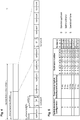
- Figure 8 a sequence of radio frames with UL/DL TDD configuration 2 (cf. Figure 5 ) is shown.
- the redundancy version of the data mapped to the downlink and special frames is shown in the first row below the subframe representation.
- the values of a downlink counter and a special counter are shown in the respective second and third row below the redundancy version.
- the counter for the downlink subframes and the counter for special subframes are independent.
- the first radio frame includes the subframes D, S, U, D, D, D, S, U, D, D.
- the data in its four different versions are mapped onto the D and S frames, which results in the counter value for D subframes respectively 0, -, -, 2, 3, 1, -, -, 0, 2 and in the counter value for S frames respectively -, 0, -, -, -, -, 2 -, -, -, wherein "-” denotes no change of the counter, even though it can also be interpreted as "not applicable” or "don't care".
- the S-frame counter increments with each S subframe onto which the data is mapped whereas the D-frame counter increments with each D subframe onto which the data is mapped.
- the increasing is in this example cyclically and sequentially repeating the predefined order 0, 2, 3, 1.
- the redundancy version corresponding to the 10 subframes for the downlink would be as follows: 0, 2, -, 3, 1, 0, 2, -, 3, 1, if there was a counter common for the S and D frames and no further rules.
- the present disclosure is not limited to the versions of data being different redundancy versions. Rather, the versions of the data to be transmitted in the respective subframes may also be repetitions of the same data.
- the circular buffer in such case is filled with one version of the data and the mapping to the special frames starts from different bit positions within this data.
- the present disclosure is meant to cover any form of versions of the data.
- any other versions such as differently interleaved versions of the same data are also possible.
- the above examples show rate matching on a bit level.
- the rate matching may also be performed on a modulation symbol level, i.e. for multiples of a bit.
- this approach may be applied to user data and/or to control data.
- Concerning the control data already the introduction of the cyclic buffer and repetitions possibly with different versions may improve the performance. Even if the control data is mapped only to the downlink subframes, the application of the circular buffer for rate matching improves the reliability of transmission.
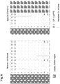
- Figure 9 illustrates the mapping of a control channel (the same is applicable also for a user data channel) as described above.
- a pointer (counter) may take four values DwPTS_0, DwPTS_1, DwPTS_2 and DwPTS_3. The incrementing of the pointer is performed for each S subframe in the predefined order of DwPTS_0, DwPTS_2, DwPTS_3 and DwPTS_1.
- the rate matching algorithm for the control channels may be performed as illustrated by the following pseudo code: wherein DwPTS idx is a counter that is incremented at each DwPTS control repetition (version) transmission and offset could be 0 for simplicity, or a different value preferably between 0 and Kw divided by the number of possible redundancy versions.
- R subblock CC denotes number of rows in a interleaving matrix as specified in detail within 3GPP TS 36.212, v.8.6.0 (or other version) in Section 5.1.4 and in particular in Subsection 5.1.4.1.1 for Turbo coding.
- Kw denotes the size of the coded data block, i.e. the length of the circular buffer for the coded data block.
- E denotes the rate matching output sequence length for the coded block.
- w denotes bits in the circular buffer, where the position within the buffer is given by the subscript index of w.
- Multiplication by 2 and division by 8 in the first line of the pseudo code above correspond to the application of 4 possible RVs.
- the version counter is cyclically incremented following a predefined order of the redundancy versions. For instance, if four redundancy versions 0-3 are available, the counter may be incremented modulo 4, i.e. 0, 1, 2, 3, 0, 1, 2, 3, 0, etc ... However, other order of the redundancy versions may be defined and cyclically repeated such as 0, 2, 1, 3, 0, 2, 1, 3, etc. or any other.
- DwPTS sizes there may be different DwPTS sizes currently in LTE (cf. cofigurations 0 to 9), also depending on the size of the cyclic prefix applied, which is configurable.
- the sequence [0,1,2,3] of redundancy versions is applied for short DwPTS and small control channel payloads and the sequence [0,2,3,1] is applied for better distribution of transmitted bits in case of long DwPTS and/or large control channel payloads.
- the sequence of versions for a special subframe with a first length may differ from the sequence of versions for a special subframe with a second length.
- the length refers to the number of bits or symbols available for mapping data thereon.
- the sequence of versions is consecutive (i.e. sequentially following the order of possible pointer positions in the circular buffer) for the first length and non-consecutive for the second length, the first length being shorter than the second length.
- the non-consecutive mapping helps reducing the overlapping data portions between the consecutive redundancy versions and thus provide more combining diversity which may result to a faster decoding (after less attempts).
- Wireless systems and among them also LTE may employ frequency hopping in order to improve reception in frequency selective fading channels.
- the frequency hopping means that at certain time period, the frequency on which the data block version is to be transmitted changes in a pseudo random manner. In LTE, the change of frequency is performed by changing the location of the PRB for the given subframe.
- the size of certain time period for MTC is still discussed in standardization. It may be beneficial to set the size of the certain time period to a multiple of subframes, for instance to a value from 4 to 20 subframes. Within such a range, the channel can usually be assumed as coherent in time, so that the radio channel can be assumed to be almost flat. This enables averaging of the channel quality over several subframes, resulting in a more reliable channel estimation.
- the values 4 to 20 should be understood as exemplary and might also span more than 20 subframes provided that the radio channel can still be assumed as almost flat.
- the frequency hopping can be performed even within a subframe or between the subframes.
- the cyclic counter may advantageously be reset to the initial value after each hop. (The same may be applied for a user data channel). Resetting of the counter after change of resource position in frequency domain provides an advantage of avoiding possible error propagation in case of a wrong understanding at the UE side. For instance, error propagation could be caused by different understanding of the number of DwPTS within a hop, or the start of the control channel transmission.
- the number and the positions of redundancy versions within the circular buffer is a function of the configured DwPTS length, the number of repetitions of the channel, and/or the number of DwPTS per radio frame.
- the positions of redundancy versions within the circular buffer may be given by the offset (which may be zero) and by the number of redundancy version under the assumption that the RVs are located equidistantly (or substantially equidistantly if the size of the circular buffer is not divisible by the number of RVs) within the circular buffer.
- the redundancy versions are thus given by the values which the pointer can take.
- the number of repetitions of the data includes all repetitions of different data versions. For instance, 50, 100 or 120 (or any other number) repetitions of a data block may be some exemplary settings for enhanced coverage. For the setting of 100 repetitions, the above exemplified four repetition versions of the data would be cyclically transmitted / received 25 times. Thus the number of repetitions of a transport block is basically equal to the number of subframes in which the transport block is carried.
- the number of special subframes per radio frame is given by the TDD UL/DL configuration and in LTE currently ranges from 1 to 2. However, in general, any number may be supported.
- the above settings for instance the number of repetitions and also number of redundancy versions may differ for the shared data channel (carrying user data) and for the control channel since a different level of reliability may be beneficial for the control channels and user data channels.
- control channels For instance, assuming that the frequency resources for control channel transmissions would hop every 4 or 8 or 16 radio frames, the following numbers could be advantageous for control channels:
- channel version refers to the redundancy versions. i.e. to the number of different values which can be taken by the special subframe pointer.
- the redundancy version counters are introduced not only for special subframes but also for normal subframes (downlink or uplink). This is illustrated in Fig. 10 , similarly to Fig. 8. Fig. 10 shows a comparison with the case in which the redundancy version counter (pointer) is only used for the special frames (the first line below the subframe structure).
- the redundancy version counter only for special subframes as shown in Figure 9 is an option.
- Different RVs are transmitted in the consecutive special subframes.
- the RV counter is advantageously introduced not just for S subframes but also for D subframes.
- control channel version counters there are two different control channel version counters: The first counter is incremented for each normal subframe and applies to normal subframes whereas the second counter incremented for each special subframe and applies to special subframe.
- the second option achieves a better balance for the redundancy than the first option.
- Figure 11 illustrates a third variant, in which the special subframe is considered together with a normal subframe for the rate matching. Accordingly, the bits (symbols) in the D and S subframes in Fig. 11 are numbered consecutively.
- the resources available in a D+S subframe are considered for the rate matching.
- the S subframe is thus seen as a logical continuation of a preceding D subframe. Referring to the example shown in Figure 6 , this would mean that a D+S subframe together offers 192 REs for transmission, i.e. for BPSK equivalent to 192 bits.
- This concept of grouping subframes into resources for rate matching may be further extended to include other D or S subframes.
- This variant may be combined with some more new RVs in D subframes for better reliability averaging.
- 8 RVs may be defined and used for coverage enhancements. This may be advantageously employed for the case where the data size before encoding is large enough so that after encoding, the number of coded bits between two RV starting positions is larger than the number of bits that can be conveyed in one subframe.
- Such a scenario can particularly occur if only few REs are available for transmission in a subframe, such as in a very short DwPTS configuration (such as DwPTS configuration 0) and/or the assignment of only one physical resource block per subframe.
- a general criterion for this variant could therefore be to determine the number of defined RVs in accordance with the number of encoded bits in the circular buffer and the offered capacity of a DwPTS assignment, which may further be adjusted up or down to match the next larger or smaller number that is advantageously an integer power of 2 for efficient signalling of the transmitted RV.
- the present invention may provide the following benefits:
- FIGS 12 and 13 illustrate the embodiments of the present invention as apparatuses and methods, respectively.
- the present disclosure provides an apparatus 1200B for transmitting data in a wireless communication system employing time division duplex.
- the apparatus may advantageously be a network node such as a base station (eNodeB in LTE) which transmits data in downlink.
- eNodeB in LTE base station
- the present disclosure is not limited thereto and the apparatus may alternatively be a wireless device such as a user equipment transmitting data in uplink.
- the apparatus may integrate functionality of both the apparatus for transmitting and apparatus for receiving data according to the present disclosure, which may be applicable for instance for wireless devices working as relays and/or hops od a multimode network.
- the apparatus 1200B comprises a memory unit 1210 for storing a data block and to be operated as a circular buffer; a transmission unit 1220 for transmitting the data block in a plurality of subframes including special subframes, a special subframe containing an uplink portion and a downlink portion separated from each other by a switching portion; and a rate matching unit 1230 for mapping the stored data block onto the plurality of subframes using the circular buffer, wherein the mapping of bits onto two different special subframes starts from different respective positions in the circular buffer.
- the memory unit 1210 may be operated as a circular buffer.
- the apparatus may further comprise a pointer storage for storing a pointer indicating a position within the circular buffer.
- the pointer storage may be a part of the memory unit 1210.
- the pointer may take several values corresponding to different positions within the circular buffer storing the data block to be transmitted. In particular, the positions may be substantially equally distributed over the buffer.
- the pointer is incremented to point to the next position from which the data is to be read from the circular buffer. If the pointer reaches the last of the positions, the following incrementing shall lead to the first position again, i.e. the incrementing is performed cyclically (modulo number of positions).
- the present disclosure is not limited to transmitting as different versions of the data different parity bits generated by the forward error correction coder.
- the different versions of the data may be also repetitions (after coding, or uncoded data with repetitions of bits or symbols) or other versions.
- the data block to be stored in the memory unit is a coded data block comprising a plurality of versions of the same data. Then, after mapping of data from the circular buffer onto a special subframe the special subframe pointer is incremented to point to the version of the data that is to be mapped onto a subsequent (next following) special subframe.
- Maintaining of separate pointers for the downlink subframes and the special subframes helps reducing the imbalance between the frequency of mapping different data block portions onto the subframes. It is noted that even if the pointers are different, the positions defined as the values which can be taken by the pointer may be the same for the downlink frames and the special frames. However, the present invention is not limited thereto and the positions may also differ for the special subframes and the downlink subframes. The difference may be achieved, for instance by a different offset applied or in another way.
- the special subframes are not considered as separate resources. Rather, the immediately preceding downlink subframe is considered to be extended by the downlink portion of the special subframe. In other words the joint resource composed of the D and S subframe is treated as a subframe.
- control data or user data may be transmitted in uplink portion of the special subframes and in uplink subframes.
- the joint resource could be beneficially formed by an uplink portion of a special subframe and the next following uplink subframe.
- the pointer is incremented cyclically, sequentially following a predefined sequence of data versions, and the predefined sequence of data versions is different for different lengths of special subframes.
- the present disclosure also provides an apparatus 1200B for transmitting control data in a wireless communication system the apparatus comprising: a memory unit 1210 for storing a control data block and to be operated as a circular buffer; a transmission unit 1230 for transmitting the control data block in a plurality of subframes; and a rate matching unit 1220 for mapping the control data block onto the plurality of subframes using a circular buffer, wherein the mapping of bits onto two different subframes starts from different respective positions in the circular buffer.
- the apparatus for receiving data comprises a receiving unit 1250 for receiving the data block in a plurality of subframes including special subframes, a special subframe containing an uplink portion and a downlink portion separated from each other by a switching portion; a memory unit 1270 for storing data block versions received; and a rate de-matching unit 1260 for extracting (de-mapping) the data block from the plurality of subframes into the memory unit using a circular buffer approach, wherein the de-mapping of bits from two different special subframes leads to different respective positions in the memory unit.
- the apparatus may further comprise a combining unit for combining different data versions received and stored in the memory unit in accordance with the rate de-matching.
- the combining may be for instance a soft combining.
- the present disclosure is not limited thereto and in general any kind of combining may be implemented.
- the combining may be performed for different redundancy versions as well as repetitions of different redundancy versions.
- the data block to be stored in the memory unit is a coded data block comprising a plurality of versions of the same data, and according to an embodiment, after the de-mapping of data from a special subframe to the memory unit, the special subframe pointer is incremented to point to the version of the data that is to be de-mapped from the subsequent special subframe.
- the pointer storage may be configured to further store a downlink subframe pointer indicating a bit position within the circular buffer and different from the special subframe pointer, wherein the downlink pointer indicates a position in the memory unit to which the data from a downlink subframe are de-mapped and is incremented for each downlink subframe from which the data is de-mapped to the memory unit.
- the special subframe pointer may also be incremented after mapping of the data to other than special subframes.
- the subframe pointer may be updated for downlink transmission for each downlink and each special subframe.
- the apparatus may further comprise a frequency hopping unit which is configured to control the change of received frequency resources on which the data in subframes is received, wherein the rate de-matching unit is configured to set the pointer to the same predetermined position after each change of the frequency resource.
- the special subframe pointer indicates a position to which the data are written to the memory unit, de-mapped from a joint resource formed by a downlink subframe and a special subframe immediately following the downlink subframe; and the special subframe pointer is incremented at each de-mapping of data from the joint resource as well as from each downlink subframe to the memory unit.
- the pointer (any of the above mentioned pointers such as special subframe pointer, downlink subframe pointer or joint D+S pointer, or even an uplink pointer or a joint S+U pointer) is incremented cyclically, sequentially following a predefined sequence of data versions, and the predefined sequence of data versions is different for different lengths of special subframes.
- the present disclosure also provides an apparatus for receiving control data in a wireless communication system the apparatus comprising: a receiving unit for receiving the control data block in a plurality of subframes; a memory unit for storing a control data block received; a rate de-matching unit for extreacting the control data block from the plurality of subframes into the memory unit using a circular buffer approach, wherein the de-mapping of bits from two different subframes leads to different respective positions in the memory unit.
- the present disclosure further provides the corresponding methods for transmitting and receiving data in a wireless communication system.
- a method 1300A for transmitting data in a wireless communication system employing time division duplex.
- the method comprises the following steps: storing 1310 a data block in a memory unit to be operated as a circular buffer; mapping 1320 the stored data block onto a plurality of subframes using circular buffer approach, wherein the mapping of bits onto two different special subframes starts from different respective positions in the circular buffer; and transmitting 1340 the data block in the plurality of subframes including special subframes, a special subframe containing an uplink portion and a downlink portion separated from each other by a switching portion.
- the step of storing may correspond for instance to receiving a transport block after forward error correction coding and temporarily storing it in a memory which is to be operated as a circular buffer (for instance by means of cyclically updating pointer at each new subframe to which the data is mapped).
- the step of updating the pointer 1330 may be performed within the rate matching and may include as described above and with respect to apparatuses updating of any of the special subframe pointer, downlink subframe pointer, uplink subframe pointer, joint D+S or S+U pointer or a common pointer, whichever is applicable according to the embodiments and examples described above.
- the transmission is performed over a wireless interface 1300, which may be for instance the wireless interface often LTE system or any other system.
- a method for receiving control data in a wireless communication system comprising: receiving the control data block in a plurality of subframes; storing in a memory unit a control data block received; extracting the control data block from the plurality of subframes into the memory unit using a circular buffer approach, wherein the de-mapping of bits from two different subframes leads to different respective positions in the memory unit.
- a computer program product comprising a computer-readable medium having a computer-readable program code embodied thereon is provided, the program code being adapted to carry out the present invention.
- a user terminal mobile terminal
- an eNodeB base station
- the user terminal and base station is adapted to perform the methods described herein, including corresponding entities to participate appropriately in the methods, such as receiver, transmitter, processors.
Landscapes
- Engineering & Computer Science (AREA)
- Signal Processing (AREA)
- Computer Networks & Wireless Communication (AREA)
- Mobile Radio Communication Systems (AREA)
Claims (8)
- Dispositif (1200B) pour un système de communication sans fil employant un duplexage à répartition temporelle, le dispositif étant adapté pour transmettre des données et comprenant :une unité de mémoire (1210) adaptée pour stocker un bloc de données et pour être exploitée en tant que tampon circulaire (700) ;une unité de transmission (1220) adaptée pour transmettre le bloc de données dans une pluralité de sous-trames incluant des sous-trames spéciales, une sous-trame spéciale contenant une partie de liaison montante et une partie de liaison descendante séparées l'une de l'autre par une partie de commutation ; etune unité d'équivalence de débit (1230) adaptée pour mapper le bloc de données stocké sur la pluralité de sous-trames en utilisant le tampon circulaire (700), dans lequel le mappage de bits sur deux sous-trames spéciales différentes commence à partir de positions respectives différentes dans le tampon circulaire (700)caractérisé parcomprenant en outre un stockage de pointeur configuré pour stocker un pointeur de sous-trame spéciale et un pointeur de sous-trame de liaison descendante différents du pointeur de sous-trame spéciale respectivement indiquant des positions de bit au sein du tampon circulaire (700),dans lequel le pointeur de sous-trame spéciale indique une première position depuis laquelle les données issues du tampon circulaire (700) sont lues et mappées sur une sous-trame spéciale et sont incrémentées pour chaque sous-trame où des données sont mappées du tampon circulaire (700) sur une sous-trame spéciale, etle pointeur de sous-trame de liaison descendante indique une deuxième position depuis laquelle les données issues du tampon circulaire (700) sont lues et mappées sur une sous-trame de liaison descendante et sont incrémentées pour chaque sous-trame où des données sont mappées du tampon circulaire (700) sur une sous-trame de liaison descendante.
- Le dispositif (1200B) selon la revendication 1, dans lequel le bloc de données à stocker dans l'unité de mémoire (1210) est un bloc de données codé comprenant une pluralité de versions des mêmes données, et
après mappage de données du tampon circulaire (700) sur une sous-trame spéciale le pointeur de sous-trame spéciale est incrémenté pour pointer vers la version des données qui est à mapper sur une sous-trame spéciale suivante. - Le dispositif (1200B) selon la revendication 1 comprenant en outre une unité de saut de fréquence qui est configurée pour contrôler le changement de ressources de fréquence transmises sur lesquelles les données dans des sous-trames sont transmises,
dans lequel l'unité d'équivalence de débit (1230) est configurée pour définir le pointeur de sous-trame spéciale sur la même position prédéterminée après chaque changement de la ressource de fréquence. - L'appareil (1200B) selon la revendication 1, dans lequel
le pointeur de sous-trame spéciale est incrémenté cycliquement, en suivant séquentiellement une séquence prédéfinie de versions de données, et
la séquence prédéfinie de versions de données est différente pour différentes longueurs de sous-trames spéciales. - Dispositif (1200A) pour un système de communication sans fil employant un duplexage à répartition temporelle, le dispositif étant adapté pour transmettre des données et comprenant :une unité de réception (1250) adaptée pour recevoir le bloc de données dans une pluralité de sous-trames incluant des sous-trames spéciales, une sous-trame spéciale contenant une partie de liaison montante et une partie de liaison descendante séparées l'une de l'autre par une partie de commutation ;une unité de mémoire (1270) adaptée pour stocker des versions de bloc de données reçues ;une unité de déséquivalence de débit (1260) adaptée pour extraire le bloc de données de la pluralité de sous-trames vers l'unité de mémoire en utilisant une approche par tampon circulaire, dans lequel le démappage de bits de deux sous-trames spéciales différentes conduit à des positions respectives différentes dans l'unité de mémoirecaractérisé parcomprenant en outre un stockage de pointeur configuré pour stocker un pointeur de sous-trame spéciale et un pointeur de sous-trame de liaison descendante différents du pointeur de sous-trame spéciale respectivement indiquant des positions de bit au sein de l'unité de mémoire (1270),dans lequel le pointeur de sous-trame spéciale indique une première position dans l'unité de mémoire (1270) à laquelle les données issues d'une sous-trame spéciale sont démappées et sont incrémentées pour chaque sous-trame spéciale de laquelle les données sont démappées vers l'unité de mémoire (1270), etle pointeur de sous-trame de liaison descendante indique une deuxième position dans l'unité de mémoire (1270) à laquelle les données issues d'une sous-trame de liaison descendante sont démappées et sont incrémentées pour chaque sous-trame de liaison descendante de laquelle les données sont démappées vers l'unité de mémoire (1270).
- Le dispositif (1200A) selon la revendication 5, dans lequel le bloc de données à stocker dans l'unité de mémoire (1270) est un bloc de données codé comprenant une pluralité de versions des mêmes données, et
après démappage de données d'une sous-trame spéciale vers l'unité de mémoire (1270), le pointeur de sous-trame spéciale est incrémenté pour pointer vers la version des données qui est à démapper d'une sous-trame spéciale suivante. - Procédé (1300A) de transmission de données dans un système de communication sans fil employant un duplexage à répartition temporelle, le procédé comprenant :stockage (1310) d'un bloc de données dans une unité de mémoire à exploiter en tant que tampon circulaire ;mappage (1320) du bloc de données stocké sur une pluralité de sous-trames en utilisant une approche par tampon circulaire, dans lequel le mappage de bits sur deux sous-trames spéciales différentes commence à partir de positions respectives différentes dans le tampon circulaire ; ettransmission (1340) du bloc de données dans la pluralité de sous-trames incluant des sous-trames spéciales, une sous-trame spéciale contenant une partie de liaison montante et une partie de liaison descendante séparées l'une de l'autre par une partie de commutationcaractérisé parstockage d'un pointeur de sous-trame spéciale et d'un pointeur de sous-trame de liaison descendante différents du pointeur de sous-trame spéciale respectivement indiquant des positions de bit au sein du tampon circulaire,dans lequel le pointeur de sous-trame spéciale indique une première position depuis laquelle les données issues du tampon circulaire sont lues et mappées sur une sous-trame spéciale et sont incrémentées pour chaque sous-trame où des données sont mappées du tampon circulaire sur une sous-trame spéciale etle pointeur de sous-trame de liaison descendante indique une deuxième position depuis laquelle les données issues du tampon circulaire sont lues et mappées sur une sous-trame de liaison descendante et sont incrémentées pour chaque sous-trame où des données sont mappées du tampon circulaire sur une sous-trame de liaison descendante.
- Procédé (1300B) de réception de données dans un système de communication sans fil employant un duplexage à répartition temporelle, le procédé comprenant :réception (1350) du bloc de données dans une pluralité de sous-trames incluant des sous-trames spéciales, une sous-trame spéciale contenant une partie de liaison montante et une partie de liaison descendante séparées l'une de l'autre par une partie de commutation ;stockage (1380) dans une unité de mémoire de versions de bloc de données reçues ;extraction (1360) du bloc de données de la pluralité de sous-trames vers l'unité de mémoire en utilisant une approche par tampon circulaire, dans lequel le démappage de bits de deux sous-trames spéciales différentes conduit à des positions respectives différentes dans l'unité de mémoirecaractérisé parstockage d'un pointeur de sous-trame spéciale et d'un pointeur de sous-trame de liaison descendante différents du pointeur de sous-trame spéciale respectivement indiquant des positions de bit au sein de l'unité de mémoire,dans lequel le pointeur de sous-trame spéciale indique une première position dans l'unité de mémoire à laquelle les données issues d'une sous-trame spéciale sont démappées et sont incrémentées pour chaque sous-trame spéciale de laquelle les données sont démappées vers l'unité de mémoire, etle pointeur de sous-trame de liaison descendante indique une deuxième position dans l'unité de mémoire à laquelle les données issues d'une sous-trame de liaison descendante sont démappées et sont incrémentées pour chaque sous-trame de liaison descendante de laquelle les données sont démappées vers l'unité de mémoire.
Applications Claiming Priority (1)
| Application Number | Priority Date | Filing Date | Title |
|---|---|---|---|
| PCT/CN2015/076870 WO2016165126A1 (fr) | 2015-04-17 | 2015-04-17 | Adaptation de débit pour un canal de communication de type machine dans un duplexage par répartition temporelle |
Publications (3)
| Publication Number | Publication Date |
|---|---|
| EP3284205A1 EP3284205A1 (fr) | 2018-02-21 |
| EP3284205A4 EP3284205A4 (fr) | 2018-12-05 |
| EP3284205B1 true EP3284205B1 (fr) | 2019-12-11 |
Family
ID=57125551
Family Applications (1)
| Application Number | Title | Priority Date | Filing Date |
|---|---|---|---|
| EP15888831.3A Active EP3284205B1 (fr) | 2015-04-17 | 2015-04-17 | Adaptation de débit pour un canal de communication de type machine dans un duplexage par répartition temporelle |
Country Status (4)
| Country | Link |
|---|---|
| US (1) | US10342026B2 (fr) |
| EP (1) | EP3284205B1 (fr) |
| JP (1) | JP6476311B2 (fr) |
| WO (1) | WO2016165126A1 (fr) |
Families Citing this family (15)
| Publication number | Priority date | Publication date | Assignee | Title |
|---|---|---|---|---|
| CN109462464B (zh) * | 2015-05-15 | 2021-10-01 | 上海华为技术有限公司 | 一种控制信道传输的方法、装置及通信节点 |
| US10841946B2 (en) * | 2015-08-31 | 2020-11-17 | Ntt Docomo, Inc. | User terminal, radio base station, and radio communication method |
| US10567110B2 (en) | 2016-03-17 | 2020-02-18 | Ofinno, Llc | Modulation, coding and redundancy version in a wireless network |
| CN108702744B (zh) * | 2016-03-18 | 2021-03-23 | 华为技术有限公司 | 网络节点、用户设备及其方法 |
| US10595315B2 (en) * | 2016-07-19 | 2020-03-17 | Qualcomm Incorporated | Enabling multi-cluster transmissions |
| WO2018082928A1 (fr) * | 2016-11-03 | 2018-05-11 | Fraunhofer-Gesellschaft zur Förderung der angewandten Forschung e.V. | Équipement utilisateur, station de base et système de communication sans fil |
| CN108631922B (zh) * | 2017-03-24 | 2024-05-10 | 中兴通讯股份有限公司 | 一种数据发送方法、数据接收方法及装置 |
| CN110537351B (zh) | 2017-04-28 | 2022-05-06 | 松下电器(美国)知识产权公司 | 测量装置和测量方法 |
| US10609708B1 (en) * | 2017-06-27 | 2020-03-31 | Sprint Spectrum L.P. | Use of TDD special subframe for transmission of small quantity of data |
| CN110999179B (zh) * | 2017-08-11 | 2022-10-25 | 瑞典爱立信有限公司 | 用于针对tdd模式下的nb-iot传输利用特殊子帧的方法和设备 |
| MX2020005239A (es) * | 2017-11-17 | 2020-10-22 | Ericsson Telefon Ab L M | Metodos de transmision y recepcion de subtramas de sib1-nb adicionales en una red de nb-iot. |
| US10805895B2 (en) * | 2017-12-01 | 2020-10-13 | Huawei Technologies Co., Ltd. | Methods, devices and systems for initial grant-free transmission determination |
| US10757601B2 (en) * | 2017-12-13 | 2020-08-25 | At&T Intellectual Property I, L.P. | Physical layer procedures for user equipment in power saving mode |
| WO2019159135A1 (fr) * | 2018-02-16 | 2019-08-22 | Telefonaktiebolaget Lm Ericsson (Publ) | Fiabilité de pcfich améliorée à l'aide d'une amplification de puissance |
| US20200358557A1 (en) * | 2019-05-10 | 2020-11-12 | Samsung Electronics Co., Ltd. | Method and apparatus for data transmission in wireless communication system |
Family Cites Families (23)
| Publication number | Priority date | Publication date | Assignee | Title |
|---|---|---|---|---|
| US7325122B2 (en) * | 2004-02-20 | 2008-01-29 | International Business Machines Corporation | Facilitating inter-DSP data communications |
| KR100970003B1 (ko) * | 2007-05-02 | 2010-07-16 | 한국전자통신연구원 | 신호 송신 방법 및 장치 |
| US8189559B2 (en) * | 2007-07-23 | 2012-05-29 | Samsung Electronics Co., Ltd. | Rate matching for hybrid ARQ operations |
| ES2387837T3 (es) * | 2007-09-26 | 2012-10-02 | Nokia Corporation | Limitación de señalización de múltiples dimensiones de carga útil para asignaciones de recursos |
| WO2009057922A1 (fr) * | 2007-10-29 | 2009-05-07 | Lg Electronics Inc. | Procédé de transmission de données au moyen d'une harq |
| CN101499895B (zh) * | 2008-02-01 | 2011-04-20 | 大唐移动通信设备有限公司 | 一种时分双工系统中的上行调度方法 |
| PL2266238T3 (pl) * | 2008-03-24 | 2015-08-31 | Nokia Technologies Oy | Konfiguracja pamięci buforowej miękkiej w systemie komunikacji |
| CN101577690A (zh) * | 2008-05-07 | 2009-11-11 | 三星电子株式会社 | Ofdm数据传输方法及系统 |
| CN101867443B (zh) * | 2009-04-14 | 2015-05-20 | 中兴通讯股份有限公司 | 速率匹配方法和装置 |
| CN102137500B (zh) * | 2010-01-26 | 2013-10-02 | 华为技术有限公司 | 传输数据的方法、基站和系统 |
| US8537755B2 (en) * | 2010-05-11 | 2013-09-17 | Qualcomm Incorporated | Rate matching device |
| JP2011249914A (ja) * | 2010-05-24 | 2011-12-08 | Panasonic Corp | 無線送信装置、無線受信装置、無線送信方法及び無線受信方法 |
| US10873425B2 (en) * | 2010-11-12 | 2020-12-22 | Qualcomm Incorporated | Acknowledgement / negative acknowledgement feedback for TDD |
| US20130258913A1 (en) * | 2012-03-30 | 2013-10-03 | Qualcomm Incorporated | Tdd pipeline processing |
| WO2014017848A1 (fr) * | 2012-07-25 | 2014-01-30 | Lg Electronics Inc. | Procédé et appareil pour la réception ou la transmission d'un signal radiofréquence (rf) |
| US9369248B2 (en) * | 2012-09-19 | 2016-06-14 | Telefonaktiebolaget Lm Ericsson (Publ) | Method and communication node for mapping an enhanced physical downlink control channel, EPDCCH, message |
| US9876615B2 (en) | 2012-11-13 | 2018-01-23 | Lg Electronics Inc. | Method and apparatus for transmitting and receiving data multiple times in consecutive subframes |
| US20150358115A1 (en) | 2013-01-16 | 2015-12-10 | Nec (China) Co., Ltd. | Method and apparatus for performing tti bundling in a tdd system |
| US9112685B2 (en) * | 2013-05-10 | 2015-08-18 | Blackberry Limited | Mechanisms for direct inter-device signaling |
| US20150173102A1 (en) * | 2013-12-12 | 2015-06-18 | Sharp Kabushiki Kaisha | Terminal apparatus, base station apparatus, communication system, communication method, and integrated circuit |
| JP6304382B2 (ja) * | 2014-07-29 | 2018-04-04 | 日本電気株式会社 | キャリアアグリゲーションでのダウンリンクharqプロセスを処理するための方法及び装置 |
| WO2016021983A1 (fr) * | 2014-08-08 | 2016-02-11 | 주식회사 아이티엘 | Procédé et appareil de communication sans fil dans un système de communication sans fil prenant en charge des communications de dispositif à dispositif |
| WO2016122242A2 (fr) * | 2015-01-29 | 2016-08-04 | 엘지전자 주식회사 | Procédé de réception d'informations de commande en liaison montante et équipement d'utilisateur associé, ainsi que procédé d'émission d'informations de commande en liaison descendante et station de base associée |
-
2015
- 2015-04-17 JP JP2017545727A patent/JP6476311B2/ja not_active Expired - Fee Related
- 2015-04-17 WO PCT/CN2015/076870 patent/WO2016165126A1/fr not_active Ceased
- 2015-04-17 US US15/563,925 patent/US10342026B2/en not_active Expired - Fee Related
- 2015-04-17 EP EP15888831.3A patent/EP3284205B1/fr active Active
Non-Patent Citations (1)
| Title |
|---|
| None * |
Also Published As
| Publication number | Publication date |
|---|---|
| EP3284205A1 (fr) | 2018-02-21 |
| EP3284205A4 (fr) | 2018-12-05 |
| WO2016165126A1 (fr) | 2016-10-20 |
| US20180132257A1 (en) | 2018-05-10 |
| JP2018517313A (ja) | 2018-06-28 |
| US10342026B2 (en) | 2019-07-02 |
| JP6476311B2 (ja) | 2019-02-27 |
Similar Documents
| Publication | Publication Date | Title |
|---|---|---|
| US12028294B2 (en) | TDD uplink/downlink re-configuration mechanism | |
| EP3284205B1 (fr) | Adaptation de débit pour un canal de communication de type machine dans un duplexage par répartition temporelle | |
| US11985639B2 (en) | Special subframe configuration for latency reduction | |
| EP2995020B1 (fr) | Configuration de liaison montante-descendante tdd flexible avec sous-trames flexibles | |
| US9936518B2 (en) | Method for transport block transmission and blind reception | |
| EP2897318A1 (fr) | Améliorations de la configuration du duplex par séparation temporelle (en anglais, Time-Division Duplex, TDD) des liaisons montantes/descendantes | |
| JP6952166B2 (ja) | 装置、方法、及び集積回路 |
Legal Events
| Date | Code | Title | Description |
|---|---|---|---|
| STAA | Information on the status of an ep patent application or granted ep patent |
Free format text: STATUS: THE INTERNATIONAL PUBLICATION HAS BEEN MADE |
|
| PUAI | Public reference made under article 153(3) epc to a published international application that has entered the european phase |
Free format text: ORIGINAL CODE: 0009012 |
|
| STAA | Information on the status of an ep patent application or granted ep patent |
Free format text: STATUS: REQUEST FOR EXAMINATION WAS MADE |
|
| 17P | Request for examination filed |
Effective date: 20170825 |
|
| AK | Designated contracting states |
Kind code of ref document: A1 Designated state(s): AL AT BE BG CH CY CZ DE DK EE ES FI FR GB GR HR HU IE IS IT LI LT LU LV MC MK MT NL NO PL PT RO RS SE SI SK SM TR |
|
| AX | Request for extension of the european patent |
Extension state: BA ME |
|
| DAV | Request for validation of the european patent (deleted) | ||
| DAX | Request for extension of the european patent (deleted) | ||
| A4 | Supplementary search report drawn up and despatched |
Effective date: 20181031 |
|
| RIC1 | Information provided on ipc code assigned before grant |
Ipc: H04L 5/22 20060101AFI20181025BHEP Ipc: H04W 72/00 20090101ALI20181025BHEP Ipc: H04L 5/14 20060101ALI20181025BHEP Ipc: H04W 72/12 20090101ALI20181025BHEP Ipc: H04L 5/00 20060101ALI20181025BHEP Ipc: H04W 72/04 20090101ALI20181025BHEP |
|
| GRAP | Despatch of communication of intention to grant a patent |
Free format text: ORIGINAL CODE: EPIDOSNIGR1 |
|
| STAA | Information on the status of an ep patent application or granted ep patent |
Free format text: STATUS: GRANT OF PATENT IS INTENDED |
|
| RIC1 | Information provided on ipc code assigned before grant |
Ipc: H04L 5/00 20060101ALI20190528BHEP Ipc: H04L 5/14 20060101ALI20190528BHEP Ipc: H04W 72/04 20090101ALI20190528BHEP Ipc: H04W 72/12 20090101ALI20190528BHEP Ipc: H04L 5/22 20060101AFI20190528BHEP Ipc: H04W 72/00 20090101ALI20190528BHEP |
|
| INTG | Intention to grant announced |
Effective date: 20190627 |
|
| GRAJ | Information related to disapproval of communication of intention to grant by the applicant or resumption of examination proceedings by the epo deleted |
Free format text: ORIGINAL CODE: EPIDOSDIGR1 |
|
| STAA | Information on the status of an ep patent application or granted ep patent |
Free format text: STATUS: REQUEST FOR EXAMINATION WAS MADE |
|
| GRAP | Despatch of communication of intention to grant a patent |
Free format text: ORIGINAL CODE: EPIDOSNIGR1 |
|
| STAA | Information on the status of an ep patent application or granted ep patent |
Free format text: STATUS: GRANT OF PATENT IS INTENDED |
|
| INTC | Intention to grant announced (deleted) | ||
| INTG | Intention to grant announced |
Effective date: 20190910 |
|
| GRAS | Grant fee paid |
Free format text: ORIGINAL CODE: EPIDOSNIGR3 |
|
| GRAA | (expected) grant |
Free format text: ORIGINAL CODE: 0009210 |
|
| STAA | Information on the status of an ep patent application or granted ep patent |
Free format text: STATUS: THE PATENT HAS BEEN GRANTED |
|
| AK | Designated contracting states |
Kind code of ref document: B1 Designated state(s): AL AT BE BG CH CY CZ DE DK EE ES FI FR GB GR HR HU IE IS IT LI LT LU LV MC MK MT NL NO PL PT RO RS SE SI SK SM TR |
|
| REG | Reference to a national code |
Ref country code: GB Ref legal event code: FG4D |
|
| REG | Reference to a national code |
Ref country code: CH Ref legal event code: EP |
|
| REG | Reference to a national code |
Ref country code: AT Ref legal event code: REF Ref document number: 1213267 Country of ref document: AT Kind code of ref document: T Effective date: 20191215 |
|
| REG | Reference to a national code |
Ref country code: DE Ref legal event code: R096 Ref document number: 602015043666 Country of ref document: DE |
|
| REG | Reference to a national code |
Ref country code: IE Ref legal event code: FG4D |
|
| REG | Reference to a national code |
Ref country code: NL Ref legal event code: MP Effective date: 20191211 |
|
| REG | Reference to a national code |
Ref country code: LT Ref legal event code: MG4D |
|
| PG25 | Lapsed in a contracting state [announced via postgrant information from national office to epo] |
Ref country code: SE Free format text: LAPSE BECAUSE OF FAILURE TO SUBMIT A TRANSLATION OF THE DESCRIPTION OR TO PAY THE FEE WITHIN THE PRESCRIBED TIME-LIMIT Effective date: 20191211 Ref country code: LV Free format text: LAPSE BECAUSE OF FAILURE TO SUBMIT A TRANSLATION OF THE DESCRIPTION OR TO PAY THE FEE WITHIN THE PRESCRIBED TIME-LIMIT Effective date: 20191211 Ref country code: LT Free format text: LAPSE BECAUSE OF FAILURE TO SUBMIT A TRANSLATION OF THE DESCRIPTION OR TO PAY THE FEE WITHIN THE PRESCRIBED TIME-LIMIT Effective date: 20191211 Ref country code: GR Free format text: LAPSE BECAUSE OF FAILURE TO SUBMIT A TRANSLATION OF THE DESCRIPTION OR TO PAY THE FEE WITHIN THE PRESCRIBED TIME-LIMIT Effective date: 20200312 Ref country code: NO Free format text: LAPSE BECAUSE OF FAILURE TO SUBMIT A TRANSLATION OF THE DESCRIPTION OR TO PAY THE FEE WITHIN THE PRESCRIBED TIME-LIMIT Effective date: 20200311 Ref country code: BG Free format text: LAPSE BECAUSE OF FAILURE TO SUBMIT A TRANSLATION OF THE DESCRIPTION OR TO PAY THE FEE WITHIN THE PRESCRIBED TIME-LIMIT Effective date: 20200311 Ref country code: FI Free format text: LAPSE BECAUSE OF FAILURE TO SUBMIT A TRANSLATION OF THE DESCRIPTION OR TO PAY THE FEE WITHIN THE PRESCRIBED TIME-LIMIT Effective date: 20191211 |
|
| PG25 | Lapsed in a contracting state [announced via postgrant information from national office to epo] |
Ref country code: RS Free format text: LAPSE BECAUSE OF FAILURE TO SUBMIT A TRANSLATION OF THE DESCRIPTION OR TO PAY THE FEE WITHIN THE PRESCRIBED TIME-LIMIT Effective date: 20191211 Ref country code: HR Free format text: LAPSE BECAUSE OF FAILURE TO SUBMIT A TRANSLATION OF THE DESCRIPTION OR TO PAY THE FEE WITHIN THE PRESCRIBED TIME-LIMIT Effective date: 20191211 |
|
| PG25 | Lapsed in a contracting state [announced via postgrant information from national office to epo] |
Ref country code: AL Free format text: LAPSE BECAUSE OF FAILURE TO SUBMIT A TRANSLATION OF THE DESCRIPTION OR TO PAY THE FEE WITHIN THE PRESCRIBED TIME-LIMIT Effective date: 20191211 |
|
| PG25 | Lapsed in a contracting state [announced via postgrant information from national office to epo] |
Ref country code: RO Free format text: LAPSE BECAUSE OF FAILURE TO SUBMIT A TRANSLATION OF THE DESCRIPTION OR TO PAY THE FEE WITHIN THE PRESCRIBED TIME-LIMIT Effective date: 20191211 Ref country code: CZ Free format text: LAPSE BECAUSE OF FAILURE TO SUBMIT A TRANSLATION OF THE DESCRIPTION OR TO PAY THE FEE WITHIN THE PRESCRIBED TIME-LIMIT Effective date: 20191211 Ref country code: PT Free format text: LAPSE BECAUSE OF FAILURE TO SUBMIT A TRANSLATION OF THE DESCRIPTION OR TO PAY THE FEE WITHIN THE PRESCRIBED TIME-LIMIT Effective date: 20200506 Ref country code: EE Free format text: LAPSE BECAUSE OF FAILURE TO SUBMIT A TRANSLATION OF THE DESCRIPTION OR TO PAY THE FEE WITHIN THE PRESCRIBED TIME-LIMIT Effective date: 20191211 Ref country code: NL Free format text: LAPSE BECAUSE OF FAILURE TO SUBMIT A TRANSLATION OF THE DESCRIPTION OR TO PAY THE FEE WITHIN THE PRESCRIBED TIME-LIMIT Effective date: 20191211 Ref country code: ES Free format text: LAPSE BECAUSE OF FAILURE TO SUBMIT A TRANSLATION OF THE DESCRIPTION OR TO PAY THE FEE WITHIN THE PRESCRIBED TIME-LIMIT Effective date: 20191211 |
|
| PG25 | Lapsed in a contracting state [announced via postgrant information from national office to epo] |
Ref country code: SK Free format text: LAPSE BECAUSE OF FAILURE TO SUBMIT A TRANSLATION OF THE DESCRIPTION OR TO PAY THE FEE WITHIN THE PRESCRIBED TIME-LIMIT Effective date: 20191211 Ref country code: IS Free format text: LAPSE BECAUSE OF FAILURE TO SUBMIT A TRANSLATION OF THE DESCRIPTION OR TO PAY THE FEE WITHIN THE PRESCRIBED TIME-LIMIT Effective date: 20200411 Ref country code: SM Free format text: LAPSE BECAUSE OF FAILURE TO SUBMIT A TRANSLATION OF THE DESCRIPTION OR TO PAY THE FEE WITHIN THE PRESCRIBED TIME-LIMIT Effective date: 20191211 |
|
| REG | Reference to a national code |
Ref country code: DE Ref legal event code: R097 Ref document number: 602015043666 Country of ref document: DE |
|
| REG | Reference to a national code |
Ref country code: AT Ref legal event code: MK05 Ref document number: 1213267 Country of ref document: AT Kind code of ref document: T Effective date: 20191211 |
|
| PLBE | No opposition filed within time limit |
Free format text: ORIGINAL CODE: 0009261 |
|
| STAA | Information on the status of an ep patent application or granted ep patent |
Free format text: STATUS: NO OPPOSITION FILED WITHIN TIME LIMIT |
|
| PG25 | Lapsed in a contracting state [announced via postgrant information from national office to epo] |
Ref country code: DK Free format text: LAPSE BECAUSE OF FAILURE TO SUBMIT A TRANSLATION OF THE DESCRIPTION OR TO PAY THE FEE WITHIN THE PRESCRIBED TIME-LIMIT Effective date: 20191211 |
|
| 26N | No opposition filed |
Effective date: 20200914 |
|
| PG25 | Lapsed in a contracting state [announced via postgrant information from national office to epo] |
Ref country code: SI Free format text: LAPSE BECAUSE OF FAILURE TO SUBMIT A TRANSLATION OF THE DESCRIPTION OR TO PAY THE FEE WITHIN THE PRESCRIBED TIME-LIMIT Effective date: 20191211 Ref country code: MC Free format text: LAPSE BECAUSE OF FAILURE TO SUBMIT A TRANSLATION OF THE DESCRIPTION OR TO PAY THE FEE WITHIN THE PRESCRIBED TIME-LIMIT Effective date: 20191211 Ref country code: AT Free format text: LAPSE BECAUSE OF FAILURE TO SUBMIT A TRANSLATION OF THE DESCRIPTION OR TO PAY THE FEE WITHIN THE PRESCRIBED TIME-LIMIT Effective date: 20191211 |
|
| REG | Reference to a national code |
Ref country code: CH Ref legal event code: PL |
|
| PG25 | Lapsed in a contracting state [announced via postgrant information from national office to epo] |
Ref country code: LI Free format text: LAPSE BECAUSE OF NON-PAYMENT OF DUE FEES Effective date: 20200430 Ref country code: IT Free format text: LAPSE BECAUSE OF FAILURE TO SUBMIT A TRANSLATION OF THE DESCRIPTION OR TO PAY THE FEE WITHIN THE PRESCRIBED TIME-LIMIT Effective date: 20191211 Ref country code: FR Free format text: LAPSE BECAUSE OF NON-PAYMENT OF DUE FEES Effective date: 20200430 Ref country code: LU Free format text: LAPSE BECAUSE OF NON-PAYMENT OF DUE FEES Effective date: 20200417 Ref country code: CH Free format text: LAPSE BECAUSE OF NON-PAYMENT OF DUE FEES Effective date: 20200430 |
|
| REG | Reference to a national code |
Ref country code: BE Ref legal event code: MM Effective date: 20200430 |
|
| PG25 | Lapsed in a contracting state [announced via postgrant information from national office to epo] |
Ref country code: BE Free format text: LAPSE BECAUSE OF NON-PAYMENT OF DUE FEES Effective date: 20200430 Ref country code: PL Free format text: LAPSE BECAUSE OF FAILURE TO SUBMIT A TRANSLATION OF THE DESCRIPTION OR TO PAY THE FEE WITHIN THE PRESCRIBED TIME-LIMIT Effective date: 20191211 |
|
| GBPC | Gb: european patent ceased through non-payment of renewal fee |
Effective date: 20200417 |
|
| PG25 | Lapsed in a contracting state [announced via postgrant information from national office to epo] |
Ref country code: GB Free format text: LAPSE BECAUSE OF NON-PAYMENT OF DUE FEES Effective date: 20200417 Ref country code: IE Free format text: LAPSE BECAUSE OF NON-PAYMENT OF DUE FEES Effective date: 20200417 |
|
| PG25 | Lapsed in a contracting state [announced via postgrant information from national office to epo] |
Ref country code: TR Free format text: LAPSE BECAUSE OF FAILURE TO SUBMIT A TRANSLATION OF THE DESCRIPTION OR TO PAY THE FEE WITHIN THE PRESCRIBED TIME-LIMIT Effective date: 20191211 Ref country code: MT Free format text: LAPSE BECAUSE OF FAILURE TO SUBMIT A TRANSLATION OF THE DESCRIPTION OR TO PAY THE FEE WITHIN THE PRESCRIBED TIME-LIMIT Effective date: 20191211 Ref country code: CY Free format text: LAPSE BECAUSE OF FAILURE TO SUBMIT A TRANSLATION OF THE DESCRIPTION OR TO PAY THE FEE WITHIN THE PRESCRIBED TIME-LIMIT Effective date: 20191211 |
|
| PG25 | Lapsed in a contracting state [announced via postgrant information from national office to epo] |
Ref country code: MK Free format text: LAPSE BECAUSE OF FAILURE TO SUBMIT A TRANSLATION OF THE DESCRIPTION OR TO PAY THE FEE WITHIN THE PRESCRIBED TIME-LIMIT Effective date: 20191211 |
|
| PGFP | Annual fee paid to national office [announced via postgrant information from national office to epo] |
Ref country code: DE Payment date: 20220420 Year of fee payment: 8 |
|
| REG | Reference to a national code |
Ref country code: DE Ref legal event code: R119 Ref document number: 602015043666 Country of ref document: DE |
|
| PG25 | Lapsed in a contracting state [announced via postgrant information from national office to epo] |
Ref country code: DE Free format text: LAPSE BECAUSE OF NON-PAYMENT OF DUE FEES Effective date: 20231103 |