EP3284301B1 - Procédé et appareil pour déterminer qu'une a-mpr d'allocation de ressources presque contiguë s'applique à une transmission de liaison montante - Google Patents
Procédé et appareil pour déterminer qu'une a-mpr d'allocation de ressources presque contiguë s'applique à une transmission de liaison montante Download PDFInfo
- Publication number
- EP3284301B1 EP3284301B1 EP16718945.5A EP16718945A EP3284301B1 EP 3284301 B1 EP3284301 B1 EP 3284301B1 EP 16718945 A EP16718945 A EP 16718945A EP 3284301 B1 EP3284301 B1 EP 3284301B1
- Authority
- EP
- European Patent Office
- Prior art keywords
- contiguous
- resource blocks
- allocation
- mpr
- resource
- Prior art date
- Legal status (The legal status is an assumption and is not a legal conclusion. Google has not performed a legal analysis and makes no representation as to the accuracy of the status listed.)
- Active
Links
Images





Classifications
-
- H—ELECTRICITY
- H04—ELECTRIC COMMUNICATION TECHNIQUE
- H04W—WIRELESS COMMUNICATION NETWORKS
- H04W52/00—Power management, e.g. Transmission Power Control [TPC] or power classes
- H04W52/04—Transmission power control [TPC]
- H04W52/06—TPC algorithms
- H04W52/14—Separate analysis of uplink or downlink
- H04W52/146—Uplink power control
-
- H—ELECTRICITY
- H04—ELECTRIC COMMUNICATION TECHNIQUE
- H04W—WIRELESS COMMUNICATION NETWORKS
- H04W52/00—Power management, e.g. Transmission Power Control [TPC] or power classes
- H04W52/04—Transmission power control [TPC]
- H04W52/30—Transmission power control [TPC] using constraints in the total amount of available transmission power
- H04W52/36—Transmission power control [TPC] using constraints in the total amount of available transmission power with a discrete range or set of values, e.g. step size, ramping or offsets
- H04W52/367—Power values between minimum and maximum limits, e.g. dynamic range
-
- H—ELECTRICITY
- H04—ELECTRIC COMMUNICATION TECHNIQUE
- H04W—WIRELESS COMMUNICATION NETWORKS
- H04W72/00—Local resource management
- H04W72/04—Wireless resource allocation
-
- H—ELECTRICITY
- H04—ELECTRIC COMMUNICATION TECHNIQUE
- H04W—WIRELESS COMMUNICATION NETWORKS
- H04W72/00—Local resource management
- H04W72/04—Wireless resource allocation
- H04W72/044—Wireless resource allocation based on the type of the allocated resource
Definitions
- the present disclosure is directed to a method and apparatus that determine that an almost-contiguous resource allocation Additional Maximum Power Reduction (A-MPR) applies to an uplink transmission power. More particularly, the present disclosure relates to determination of uplink transmission power for contiguous, non-contiguous, and almost-contiguous resource-block allocations.
- A-MPR Additional Maximum Power Reduction
- wireless communication devices such as User Equipment (UE) communicate with other communication devices using wireless signals.
- Carrier aggregation is a feature for increasing peak and average user throughput of UEs by enabling the UE to exploit unused resources on a secondary component carrier.
- the resource blocks on the two component carriers are segregated so that UE's assigned to a first component carrier cannot be allocated unused resources on the second component carrier.
- Carrier aggregation is especially beneficial if the loading of the two component carriers is unbalanced so that many of the resource blocks on the second component carrier would be unused if they cannot be assigned to UE's on the first component carrier.
- Carrier aggregation also increases the peak data rate achievable by the UE.
- A-MPR Additional Maximum Power Reduction
- the A-MPR is a function of the allocation ratio which is defined as the ratio of the number of RB's allocated to the UE over all carriers, N RB_alloc , to the sum of the total number of RB's over the aggregated carriers N RB_agg .
- the A-MPR is in tabular form and is a function of one or more of the allocation parameters RB start , RB end , and L CRB , where L CRB is the number of contiguous RB's in the contiguous allocation.
- the A-MPR allowed for a non-contiguous allocation is much larger than the A-MPR allocated for contiguous allocation.
- the A-MPR allowed for a non-contiguous allocation can be more than 4.5 dB greater than the A-MPR allowed for a contiguous allocation with the same allocation ratio. From a system perspective, large A-MPR is detrimental since a reduction in UE transmit power reduces the range and/or throughput achievable on the uplink.
- US 2014/341126 A1 describes allocating quasi-contiguous uplink data resources for a user device.
- Transmission of data comprises at least two data clusters of sub carriers expanding over gaps reserved for uplink control channel in order, for example, to mitigate transmission power reductions due to multi-cluster transmission.
- A-MPR for Contiguous CA with Almost-Contiguous Resource Allocations and CA_NS Signalling is a paper from 3GPP TSG RAN WG4 Meeting #72bis held in Singapore on 6-10 October 2014 .
- the paper was submitted by Motorola Mobility and has a 3GPP reference number R4-146503 and an EPO reference number XP050872945.
- This paper outlines a proposal for reducing the A-MPR for PUSCH allocations which are almost contiguous except due to puncturing of the PUCCH region or other scheduling restrictions.
- Embodiments provide a method and apparatus that determine that an almost-contiguous resource allocation Additional Maximum Power Reduction (A-MPR) applies to an uplink transmission power.
- A-MPR Additional Maximum Power Reduction
- an indication of a resource allocation of resource blocks for a transmission can be received.
- the resource allocation can be ascertained to be a non-contiguous allocation of resource blocks.
- An almost-contiguous resource allocation Additional Maximum Power Reduction (A-MPR) can be determined to apply to an uplink transmission power for the transmission.
- An almost-contiguous resource allocation can be defined as a contiguous resource allocation of resource blocks from which resource blocks are punctured and the punctured resource blocks are contained in a contiguous region overlapping a boundary between the lower frequency carrier and the adjacent upper frequency carrier.
- the punctured resource blocks can be resource blocks that are not allocated for the transmission.
- the transmission can be performed based on the uplink transmission power with the applied A-MPR.
- a non-contiguous allocation of resource blocks can be allocated for an uplink transmission from a mobile station.
- An indication of the non-contiguous allocation of resource blocks for the uplink transmission can be transmitted.
- An almost-contiguous resource allocation Additional Maximum Power Reduction (A-MPR) can be determined to apply to an uplink transmission power for the uplink transmission.
- A-MPR Additional Maximum Power Reduction
- An almost-contiguous resource allocation can be defined as a contiguous resource allocation of resource blocks from which resource blocks are punctured and the punctured resource blocks are contained in a contiguous region overlapping a boundary between the lower frequency carrier and the adjacent upper frequency carrier.
- the punctured resource blocks can be resource blocks that are not allocated for the transmission.
- An uplink transmission can be received based on the uplink transmission power with the applied A-MPR.
- FIG. 1 is an example illustration of a block diagram 100 including a mobile station 105, such as a receiving device and/or transmitting device, and a wireless network 115 according to a possible embodiment.
- the mobile station 105 is configured for communication with the wireless network 115 via a base station 120, such as a transmitting device and/or receiving device like an eNB.
- a base station 120 such as a transmitting device and/or receiving device like an eNB.
- Possible implementations of the mobile station 105 include a mobile phone, a smartphone, a tablet computer, a laptop, or other computing device.
- the wireless network 115 is a cellular, such as a Long Term Evolution (LTE), network.
- the wireless network 115 is a Wi-Fi network, a Wireless Local Area Network (WLAN), or any other wireless network.
- LTE Long Term Evolution
- WLAN Wireless Local Area Network
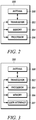
- FIG. 2 is an example illustration of a block diagram 200 showing a base station, such as the base station 120, according to a possible embodiment.
- the base station include an Evolved Universal Terrestrial Radio Access base station, an Evolved NodeB (eNB), a transmission point, a Remote Radio Head, a home eNB, and a femtocell.
- the base station is an eNB that controls a macrocell of the wireless network 115.
- the base station may include multiple network entities.
- the base station may in fact be two or more base stations operating in conjunction with one another to operate as a single base station or network entity.
- the base station may also be a portion of another network entity.
- the base station includes a transceiver 202, which can transmit data to and receive data from other devices such as the mobile station 105.
- the base station also includes at least one memory 204 and a processor 206 that can execute programs stored in the memory 204.
- the processor 206 writes data to and reads data from the memory 204.
- the transceiver 202 receives data from the processor 206 and transmits Radio Frequency ("RF") signals representing the data via antenna 208.
- RF Radio Frequency
- the transceiver 202 receives RF signals, converts the RF signals into appropriately formatted data, and provides the data to the processor 206.
- the processor 206 retrieves instructions from the memory 204 and, based on those instructions, provides outgoing data to, or receives incoming data from the transceiver 202.
- the base station is configured to allocate radio resources, such as frames, subframes, resource blocks, uplink carriers, downlink carriers, subcarriers, and other radio resources, for mobile stations, such as the mobile station 105.
- the radio resources can be allocated for communication between a mobile station and the base station, such as an uplink transmission from the mobile station to the base station.
- the base station is configured to send a control message that indicates allocated radio resources to the mobile station.
- the base station in one example allocates a contiguous allocation of resource blocks for the uplink transmission. In another example, the base station allocates a non-contiguous allocation of resource blocks for the uplink transmission. In some embodiments, the base station performs carrier aggregation of two or more carriers (e.g., uplink carriers). In this case, the allocation of resource blocks can include resource blocks on two or more adjacent uplink carriers.
- FIG. 3 is an example illustration of a block diagram 300 showing a mobile station, such as the mobile station 105, according to a possible embodiment.
- the mobile station includes a transceiver 302 configured to transmit data to and receive data from other devices such as the base station 120.
- the mobile station also includes a processor 304 that executes stored programs and at least one memory 306.
- the processor 304 writes data to and reads data from the memory 306.
- the mobile station includes a user interface 307 having a keypad, display screen, touch screen, microphone, speaker, or the like.
- the transceiver 302 receives data from the processor 304 and transmits RF signals representing the data via an antenna 308.
- the transceiver 302 receives RF signals, converts the RF signals into appropriately formatted data, and provides the data to the processor 304.
- the processor 304 retrieves instructions from the memory 306 and, based on those instructions, provides outgoing data to, or receives incoming data from, the transceiver 302.
- the user interface 307 displays the output of various application programs executed by the processor 304.
- the user interface 307 additionally includes on-screen buttons that the user can press in order to cause the mobile station to respond.
- Content shown on the user interface 307 is generally provided to the user interface at the direction of the processor 304.
- information received through the user interface 307 is provided to the processor 304, which may then cause the mobile station to carry out a function whose effects may or may not necessarily be apparent to a user.
- FIG. 4 is an example diagram 400 that shows a non-contiguous allocation of resource blocks for an uplink transmission by a mobile station, such as the mobile station 105, according to a possible embodiment.
- two adjacent component carriers (“CC1" and "CC2") include an allocation of resource blocks allocated by the base station for the uplink transmission.
- the allocation includes a first contiguous set of resource blocks on CC1, with a first resource block at RB_start_CC1 and bandwidth of L_CRB_CC1.
- the allocation also includes a second contiguous set of resource blocks on CC2, with a first resource block at RB_start_CC2 and bandwidth of L_CRB_CC2.
- the first and second sets of resource blocks are separated or "punctured" by resource blocks for the PUCCH on both CC1 and CC2.
- An overall bandwidth of the allocation is denoted as L_CRB, and includes the bandwidth of the first set of resource blocks, the bandwidth of the second set of resource blocks, and the punctured PUCCH resource blocks on both CC1 and CC2.
- CA_NS carrier aggregation signaling value
- the A-MPR for a corresponding contiguous allocation can be used with an appropriate offset, or correction factor.
- An example of such an almost-contiguous allocation would be an allocation that is contiguous except for the PUCCH region (e.g., a contiguous allocation from which the PUCCH resource blocks have been punctured as illustrated in the diagram 400).
- the punctured resource blocks can be allocated to semi-persistently scheduled Physical Uplink Shared Channel (PUSCH) resource blocks or for other purposes.
- PUSCH Physical Uplink Shared Channel
- a second non-contiguous A-MPR for any non-contiguous allocation can be derived from the A-MPR for a corresponding contiguous allocation with a correction factor, where the size of the correction factor depends on both the number of resource blocks in the corresponding contiguous allocation and the number of resource blocks punctured from the corresponding contiguous allocation.
- the second A-MPR derived from the corresponding contiguous allocation will be less than the non-contiguous A-MPR formula defined in TS 36.101, while in other cases, the second A-MPR will be greater than the non-contiguous A-MPR defined in TS 36.101.
- the mobile station determines an overall bandwidth (e.g., L_CRB of diagram 400) of the allocation by filling in any gaps of unallocated resource blocks. Equivalently, the overall bandwidth of the non-contiguous allocation can be defined as the bandwidth L_CRB (in resource blocks) of the smallest contiguous allocation that contains the non-contiguous allocation.
- the mobile station determines the allowed A-MPR from the appropriate contiguous allocation A-MPR table using the determined overall bandwidth. The mobile station then uses an allocation correction factor added to the A-MPR value obtained from the tables.
- the allocation correction factor ensures that the power spectral density of the non-contiguous allocation is the same or less than that of the corresponding contiguous allocation from which its A-MPR was derived. More specifically, the A-MPR for the non-contiguous allocation is increased by the ratio of the number of resource blocks in the contiguous allocation (e.g., the non-contiguous allocation with gaps filled in) to the number of resource blocks in the non-contiguous allocation.
- A-MPR-C denote the A-MPR allowed for a contiguous allocation of L resource blocks
- A-MPR-NC2 denote the second A-MPR allowed for a corresponding non-contiguous allocation in which K resource blocks have been punctured out of the contiguous allocation of L resource blocks.
- the A-MPR-NC2 is determined as the A-MPR-C with an allocation correction factor A-MPR-CF:
- correction factor A-MPR-CF 10 ⁇ log 10 L / M .
- the resource-block allocation for the PUSCH transmissions in CC1 is such that the last allocated resource block is at the beginning of the higher frequency PUCCH region.
- CC2 there is simultaneously a PUSCH transmission with RB_Start at the end of the lower frequency PUCCH region.
- the A-MPR value for the aggregated component carriers is the allowed maximum output power reduction applied to transmissions on the Primary Component Carrier and the Secondary Component Carrier for contiguously aggregated component carriers.
- L_CRB_CC1 and L_CRB_CC2 RBs start at B _start 1 and RB_start2, respectively.
- the PUCCH region of each component carrier may be different but must have at least one resource block so that: L CRB > L CRB _ CC 1 + L CRB _ CC 2
- Each 15 MHz carrier has 75 resource blocks, so we number the resulting aggregated resource blocks 0, 1, ..., 149.
- the mobile station is assigned a non-contiguous allocation of resource blocks 32 through 72 and 77 through 117.
- the number of resource blocks L in the smallest contiguous allocation containing this non-contiguous allocation is 86 resource blocks.
- the number of resource blocks K punctured from this smallest contiguous allocation is 4.
- the punctured resource blocks 73 and 74 may correspond to the higher frequency PUCCH region of the lower frequency component carrier, while the resource blocks 75 and 76 may correspond to the lower frequency PUCCH region of the higher frequency component carrier.
- the A-MPR for the contiguous allocation is 5 dB.
- Table 6.2.4A.1-1 (from 3GPP TS 36.101): Contiguous Allocation A-MPR for CA_NS_01 CA_1C: CA_NS_01 RB _Start L _CRB [RBs] RB _start + L _CRB [RBs] A-MPR for QPSK and 16-QAM[dB] 100 RB / 100 RB 0 - 23 and 176 - 199 > 0 n/a ⁇ 12.0 24 - 105 > 64 n/a ⁇ 6.0 106 - 175 n/a > 175 ⁇ 5.0 75 RB / 75 RB 0 - 6 and 143 - 149 0 ⁇ L_ CRB ⁇ 10 n/a ⁇ 11.0 > 10 n/a ⁇ 6.0 7 - 90 > 44 n/a ⁇ 5.0 91 - 142 n/a > 142 ⁇ 2.0 Note 1: RB _start indicates the lowest RB index of transmitted resource blocks.
- L _CRB is the length of a contiguous resource-block allocation.
- Note 3 For intra-subframe frequency hopping which intersects regions, notes 1 and 2 apply on a per slot basis.
- Note 4 For intra-subframe frequency hopping which intersects regions, the larger A-MPR value may be applied for both slots in the subframe.
- the A-MPR determined using the second non-contiguous method is 3.5 dB less than the A-MPR determined using the non-contiguous method specified in TS 36.101.
- Other examples of improved A-MPR values for various CA_NS values will be apparent to those skilled in the art.
- the allocation correction factor provides for a larger A-MPR than the allocation ratio-based method already defined in TS 36.101.
- the allocation correction factor tends to work well when the number of punctured resource blocks K is small in comparison to the number of resource blocks L in the smallest containing non-contiguous allocation so that the allocation correction factor is small.
- the second non-contiguous method for determining A-MPR can perform poorly in that it allows much more A-MPR than is necessary in order to meet the emissions requirements.
- a second example is now described for carrier aggregation for the 15 MHz + 15 MHz case in combination with CA_NS_01 signaling.
- the number of resource blocks L of the smallest contiguous allocation containing the two allocated resource blocks is 150
- the number of punctured resource blocks K is 148
- the A-MPR formula in TS 36.101 gives an A-MPR value equal to 16.7 dB.
- the A-MPR is determined for the smallest contiguous allocation containing the non-contiguous allocation containing the non-contiguous allocation. For this example, the number of resource blocks L of the smallest containing contiguous allocation is 150. From Table 6.2.4A.1-1 in TS 36.101, the A-MPR for this contiguous allocation is 6 dB. The second A-MPR is then determined by adding a correction factor to this contiguous A-MPR.
- the number of resource blocks L for the smallest containing contiguous allocation is 150
- the number of punctured resource blocks K is 148
- the A-MPR determined using the second non-contiguous method is 8 dB greater than the A-MPR determined using the non-contiguous method.
- the existing method for computing A-MPR in TS 36.101 for computing A-MPR for non-contiguous allocations is preferred to the non-contiguous method because the resulting A-MPR is less.
- the A-MPR for the second non-contiguous method is less than the A-MPR for the non-contiguous method, and for some examples the A-MPR for the second non-contiguous method is greater than for the non-contiguous method.
- A-MPR-CF is equivalent to a limitation on the ratio L/(L-K) for the non-contiguous allocation, where L is the number of resource blocks in the smallest contiguous allocation containing the non-contiguous allocation, and where K is the number of resource blocks punctured from the allocation.
- the log function can be implemented as a set of thresholds applied to the ratio L/(L-K), or equivalently L/M, where a ratio that falls between two such thresholds is assigned a correction factor A-MPR-CF which is the appropriate multiple of 0.5 dB.
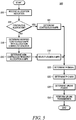
- FIG. 5 is an example flowchart 500 of a method for calculating an uplink transmission power according to a possible embodiment.
- the method may be carried out by a mobile station, such as the mobile station 105.
- the mobile station selects a minimum of two A-MPR values for determination of uplink transmission power.
- the mobile station receives (Step 505) an allocation indication from the base station.
- the allocation indication in one example is a control message that indicates radio resources (e.g., resource blocks) allocated to the mobile station by the base station.
- the mobile station determines (Step 510) whether the allocation is a contiguous allocation.
- the mobile station determines (Step 515) a contiguous A-MPR using the contiguous allocation tables as defined in TS 36.101.
- the mobile station is allowed to set its configured maximum output power P CMAX,c for a serving cell c (e.g., for a cell provided by the base station) and also its total configured maximum output power P CMAX , as described in TS 36.101 (see section 6.2.5A).
- the total configured maximum output power P CMAX is to be set between P CMAX_L ⁇ P CMAX ⁇ P CMAX_H .
- the mobile station determines (Step 520) lower bound P CMAX_L based on the contiguous A-MPR according to TS 36.101. The mobile station then determines (Step 525) the P CMAX based on the P CMAX_L and determines (Step 530) the uplink transmission power. The mobile station performs (Step 535) the uplink transmission based on the uplink transmission power.
- the mobile station determines (Step 540) a first A-MPR as a modified contiguous A-MPR with an allocation correction factor.
- the first A-MPR is based on a smallest contiguous allocation containing the non-contiguous allocation and the allocation correction factor.
- the mobile station determines the smallest contiguous allocation by filling in any gaps of unallocated resource blocks in the allocation; however, the "smallest contiguous allocation" is not actually allocated and is thus a hypothetical smallest contiguous allocation, as will be understood by those skilled in the art.
- the mobile station uses the smallest contiguous allocation containing the non-contiguous allocation to determine a contiguous A-MPR using the contiguous allocation tables as defined in TS 36.101.
- the contiguous allocation table lookup is based on at least one of a starting index of the non-contiguous allocation, an ending index of the non-contiguous allocation, the number M of allocated resource blocks in the non-contiguous allocation, or a modulation and coding scheme for the uplink transmission.
- the mobile station determines the allocation correction factor based on a ratio of a number L of resource blocks in the smallest contiguous allocation containing the non-contiguous allocation to a number M of resource blocks in the non-contiguous allocation. For example, the mobile station determines the allocation correction factor as 10 log 10 ( L / M ) . The mobile station determines the first A-MPR as a sum of the contiguous A-MPR and the allocation correction factor.
- the mobile station determines (Step 545) a second A-MPR as a non-contiguous resource allocation A-MPR for the allocation. For example, the mobile station calculates the A-MPR by performing a predetermined function based on the allocation ratio, as described in TS 36.101.
- the mobile station determines the allocation ratio as a ratio of a number M of resource blocks in the non-contiguous allocation to a maximum number N RB_agg of aggregated resource blocks available for the uplink transmission.
- the maximum number may be for a single carrier (e.g., 25 resource blocks for a 5 MHz carrier) or for multiple aggregated carriers (e.g., 150 resource blocks for two aggregated 15 MHz carriers).
- the mobile station selects the predetermined function based on the CA_NS value.
- the mobile station determines a maximum output power based on the allocation ratio and the functions defined in TS 36.101 Sections 6.2.3A and 6.2.4A.
- the mobile station selects (Step 550) a lesser of the first and second A-MPRs.
- the mobile station applies the CEIL function to the first A-MPR and the second A-MPR prior to selecting the lesser of the first and second A-MPRs.
- the mobile station calculates the uplink transmission power based on the selected A-MPR. For example, the mobile station performs Steps 520, 525, and 530 using the selected A-MPR instead of the contiguous A-MPR. The mobile station then performs (Step 535) the uplink transmission based on the uplink transmission power.
- FIG. 6 is a flowchart 600 of a method for decoding an uplink transmission according to a possible embodiment.
- the method may be carried out by a base station, such as the base station 120.
- the base station allocates (Step 605) a non-contiguous allocation of resource blocks for the uplink transmission from the mobile station.
- the base station sends an indication of the allocated resource blocks to the mobile station (e.g., via a control message).
- the base station determines (Step 610) a first A-MPR based on a smallest contiguous allocation containing the non-contiguous allocation and an allocation correction factor.
- the base station determines the allocation correction factor based on a ratio of a number L of resource blocks in the smallest contiguous allocation to a number M of resource blocks in the non-contiguous allocation. For example, the base station determines the allocation correction factor as 10 log 10 (L / M ) .
- the base station determines the first A-MPR as a sum of the contiguous A-MPR and the allocation correction factor.
- the base station selects (Step 620) a lesser of the first and second A-MPRs.
- the base station decodes (Step 625) a received uplink transmission based on the non-contiguous allocation of resource blocks and the selected A-MPR. For example, the base station receives the uplink transmission using the allocated resource blocks.
- the base station selects a modulation and coding scheme based on the selected A-MPR.
- the base station sends the selected MCS to the mobile station in the control message and decodes the uplink transmission using the selected MCS.
- the base station also performs channel estimation, including path loss estimation, for the uplink transmission based on the selected A-MPR.
- an almost-contiguous resource allocation is a resource allocation which is contiguous across a boundary between the two carriers except that it is punctured by the PUCCH region.
- an almost-contiguous A-MPR can be the sum of the A-MPR for the smallest contiguous allocation containing the almost-contiguous allocation and 10xlog of the ratio of the number of RB's in the smallest containing contiguous allocation and the number of RB's in the almost-contiguous allocation.
- an almost-contiguous allocation can be defined as a non-contiguous resource allocation spanning the boundary between two aggregated carriers which is equivalent to a first contiguous resource allocation punctured by a second contiguous resource allocation where the second contiguous resource allocation spans the boundary between the aggregated carriers.
- the definition may be too general. For this definition, an allocation consisting of two RB's with the first RB being the lowest frequency RB on the first carrier and the second RB being the highest frequency RB on the upper carrier, would be classified as almost-contiguous, and the almost-contiguous A-MPR would apply (the final A-MPR is the minimum of the almost-contiguous A-MPR and the non-contiguous A-MPR).
- the estimate of the A-MPR that is needed for the almost-contiguous resource allocation will be most accurate when it is based on the A-MPR for a contiguous allocation that is only slightly different from the almost-contiguous allocation. For this example with only two RB's, the allowed A-MPR would be based on a contiguous allocation having 200 RB's.
- Another factor with such a general definition is that it may be difficult to verify by simulation that the allowed A-MPR is sufficient, since the number of cases to simulate is very large. In general, it may be necessary to simulate every possible contiguous allocation for every possible gap size in order to verify that the allowed A-MPR is sufficient.
- a final factor with such a general definition is that it may be more general than is necessary in order to solve the problem of the PUCCH blocking contiguous allocations, since the PUCCH region is typically fairly small and is generally allocated at the edge of the carrier.
- embodiments can provide for determining when almost-contiguous A-MPR apply should apply. Furthermore, depending on when almost-contiguous A-MPR applied, embodiments can provide for signaling, or the absence thereof, to support the application.
- almost-contiguous A-MPR can apply for PUCCH puncturing.
- the almost-contiguous A-MPR may only apply for PUCCH puncturing.
- the UE can be informed that the allocation is only punctured by PUCCH by signalling the entire PUCCH region to the UE, using Radio Link Control (RLC) signaling, via a System Information Block (SIB), or by any other method of signalling.
- RLC Radio Link Control
- SIB System Information Block
- the UE can also be informed that the allocation is only punctured by PUCCH by the eNB sending a bit with each allocation indicating the allocation is only punctured by the PUCCH.
- almost-contiguous A-MPR can apply when the gap is less than a maximum value, W, of RB's.
- W a maximum value
- the maximum value of W can be fixed in the specification, can be configured by the eNB subject to a maximum value, or can be otherwise determined.
- the maximum value can be signaled to the UE from the eNB.
- the maximum value of W can be specified in 36.101.
- W can be specified per CA combination, per bandwidth combination, and per CA_NS_0x signaled. It also may be sufficient to specify a single value that applies for all CA combinations, all bandwidth combinations, and all CA_NS_0x.
- contiguous A-MPR can apply when a left gap is less than X and a right gap is less than Y.
- the values of X and Y can be fixed in the specification or can be configured by the eNB subject to a maximum value in the specification. If X and Y are configured, these values can be signaled or otherwise provided to the UE.
- the maximum value of X and Y can be specified in 36.101.
- X and Y can also be specified per CA combination, per bandwidth combination, and per CA_NS_0x signaled. It may further be sufficient to specify a single value that applies for all CA combinations, all bandwidth combinations, and all CA_NS_0x.
- FIG. 7 is an example flowchart 700 illustrating the operation of a wireless communication device, such as the mobile station 105, the base station 120, and/or any other device that communicates over a wireless network, according to a possible embodiment.
- a wireless communication device such as the mobile station 105, the base station 120, and/or any other device that communicates over a wireless network, according to a possible embodiment.
- an indication of a resource allocation of resource blocks for a transmission can be received.
- the resource allocation can be ascertained to be a non-contiguous allocation of resource blocks.
- a contiguous allocation of resource blocks can be a resource allocation of consecutive resource blocks within a lower frequency carrier, such as the component carrier CC1 described above, and an adjacent upper frequency carrier, such as the component carrier CC2 described above, that is adjacent to the lower frequency carrier in the frequency domain.
- a contiguous resource allocation can be defined as a resource allocation of consecutive resource blocks across contiguously aggregated carriers, such as the two adjacent component carriers CC1 and CC2 described above.
- a carrier can be a bandwidth configuration used for transmission in LTE.
- a nominal gap between contiguously aggregated carriers due to the nominal channel spacing can be allowed while still considering the resource allocation a contiguous resource allocation.
- a non-contiguous allocation can include at least one resource block that is not allocated for the transmission in between resource blocks that are allocated for the transmission in the resource allocation.
- the resource allocation can be determined to be non-contiguous based on the allocation itself, based on information in the indication of the resource allocation, or based on any other element for determining that a resource allocation is non-contiguous.
- an almost-contiguous resource allocation Additional Maximum Power Reduction can be determined to apply to an uplink transmission power for the transmission.
- An almost-contiguous resource allocation is defined as a contiguous resource allocation of resource blocks, such as the resource blocks in the bandwidth L_CRB described above, from which resource blocks are punctured and the punctured resource blocks are contained in a contiguous region overlapping a boundary between the lower frequency carrier and the adjacent upper frequency carrier, such as a boundary between the two adjacent component carriers CC1 and CC2 described above.
- Punctured resource blocks can be resource blocks that are not allocated for the transmission.
- an almost-contiguous allocation can be a non-contiguous allocation where the allocation is contiguous but for the punctured resource blocks contained in the contiguous region overlapping the boundary between the lower frequency carrier and the adjacent upper frequency carrier.
- a number of resource blocks in a first part of the contiguous region overlapping the boundary and contained within the lower frequency carrier can be less than a lower frequency carrier maximum value.
- a number of resource blocks in a second part of the contiguous region overlapping the boundary and contained within the upper frequency carrier can be less than an upper frequency carrier maximum value.
- the total resource blocks in the contiguous region overlapping the boundary can be less than a maximum value.
- the punctured resource blocks in the contiguous region overlapping the boundary can be contiguous punctured resource blocks.
- the contiguous punctured resource blocks can create a gap between contiguous resource blocks in the non-contiguous allocation of resource blocks.
- the gap can include at least one resource block and a size of a gap can be less than a maximum value.
- a signal can be received that indicates the maximum value, the maximum value can be preset, or the maximum value can be otherwise determined.
- the maximum value of the size of the gap can be the size of a control channel.
- the control channel can be a Physical Uplink Control Channel (PUCCH).
- the entire PUCCH can be signaled to the device, such as by using Radio Link Control (RLC) signaling, using a System Information Block (SIB), or by using any other method for signaling a PUCCH.
- RLC Radio Link Control
- SIB System Information Block
- the signaling device can send a bit with each non-contiguous allocation indicating the allocation is only punctured by the PUCCH.
- the gap can also be for Physical Uplink Shared Channel (PUSCH) resource blocks and/or for other purposes.
- PUSCH Physical Uplink Shared Channel
- the maximum value of the size of the gap can also be a size of the total punctured resource blocks in the lower frequency carrier being less than a maximum value and a size of the total punctured resource blocks in the upper frequency carrier being less than a maximum value.
- the maximum value can be the same for a carrier aggregation combination, a bandwidth combination, and/or a carrier aggregation network signaling value.
- the maximum value can be based on a carrier aggregation combination, a bandwidth combination, and/or a carrier aggregation network signaling value.
- a carrier aggregation network signaling value For example, as discussed above, for contiguous allocations, there can be up to nine or more tables defined that can specify allowed A-MPR values based on a Carrier Aggregation Network Signaling value (CA_NS).
- CA_NS Carrier Aggregation Network Signaling value
- the allowed A-MPR values for non-contiguous allocations can be defined in up to nine or more formulas based on a carrier aggregation network signaling value.
- the carrier aggregation network signaling value can indicate extra requirements on transmitter emissions, such as a maximum power spectral density in a given frequency range and other extra requirements on transmitter emissions.
- the carrier aggregation network signaling value can also indicate extra A-MPR allowed to meet the extra emission requirements.
- CA_NS signaling can be used for intra-band contiguous aggregation. The first of these formulas can apply in the event that CA_NS_31 is signaled and no extra emissions requirements apply. For example, CA_NS_31 can be used for no extra requirements. The eight remaining formulas can be defined for use with the signaling of CA_NS_01, CA_NS_02, CA_NS_03, CA_NS_04, CA_NS_05, CA_NS_06, CA_NS_07, and CA_NS_08. Other tables, other carrier aggregation network signaling values, and different formulas can also be used.
- a transmitting device such as a UE, can transmit a maximum output power that is within a range of power values set by the specification.
- the maximum output power can depend on a set of resource blocks allocated to the UE for transmission.
- the A-MPR can be an additional maximum power reduction that the UE can use to reduce the allowed minimum value of its maximum output power.
- Almost-contiguous can also be considered mostly-contiguous, partially-contiguous, or any other term that indicates a size of a gap between contiguous resource blocks, such as a gap between L_CRB_CC1 and L_CRB_CC2 described above, in a non-contiguous allocation of resource blocks being less than a maximum value.
- the transmission can be performed based on the uplink transmission power with the applied A-MPR.
- the transmission can be a carrier aggregation uplink transmission.
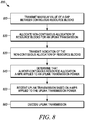
- FIG. 8 is an example flowchart 800 illustrating the operation of a wireless communication device, such as the mobile station 105, the base station 120, and/or any other device that communicates over a wireless network, according to a possible embodiment.
- a signal indicating a maximum value of a gap between contiguous resource blocks for an almost-contiguous resource allocation can be transmitted.
- a non-contiguous allocation of resource blocks can be allocated for an uplink transmission from a mobile station.
- an indication of the non-contiguous allocation of resource blocks can be transmitted for the uplink transmission from the mobile station.
- an almost-contiguous resource allocation Additional Maximum Power Reduction can be determined to apply to an uplink transmission power for the transmission.
- the almost-contiguous resource allocation can be defined as a contiguous resource allocation of resource blocks from which resource blocks are punctured and the punctured resource blocks are contained in a contiguous region overlapping a boundary between the lower frequency carrier and the adjacent upper frequency carrier.
- the punctured resource blocks can be resource blocks that are not allocated for the transmission.
- the punctured resource blocks can create a gap between contiguous resource blocks in the non-contiguous allocation of resource blocks.
- the size of the gap can be less than a maximum value.
- the maximum value of the gap size can be based on the signal indicating the maximum value, can be predetermined, or can be otherwise determined.
- an uplink transmission can be received based on the uplink transmission power with the applied A-MPR.
- the uplink transmission can be decoded based on the non-contiguous allocation of resource blocks and the uplink transmission power with the applied A-MPR.
- FIG. 9 is an example block diagram of an apparatus 900, such as the mobile station 105, the base station 120, and/or any other device that communicates over a wireless network, according to a possible embodiment.
- the apparatus 900 can include a housing 910, a controller 920 within the housing 910, audio input and output circuitry 930 coupled to the controller 920, a display 940 coupled to the controller 920, a transceiver 950 coupled to the controller 920, antennas 952 and 954 coupled to the transceiver 950, a user interface 960 coupled to the controller 920, a memory 970 coupled to the controller 920, and a network interface 980 coupled to the controller 920. All of the illustrated elements of the apparatus 900 may not be necessary depending on the implementation of the apparatus 900.
- the apparatus 900 can perform the methods described in all the embodiments.
- the display 940 can be a viewfinder, a liquid crystal display (LCD), a light emitting diode (LED) display, a plasma display, a projection display, a touch screen, or any other device that displays information.
- the transceiver 950 can include a transmitter and/or a receiver.
- the audio input and output circuitry 930 can include a microphone, a speaker, a transducer, or any other audio input and output circuitry.
- the user interface 960 can include a keypad, a keyboard, buttons, a touch pad, a joystick, a touch screen display, another additional display, or any other device useful for providing an interface between a user and an electronic device.
- the network interface 980 can be a Universal Serial Bus (USB) port, an Ethernet port, an infrared transmitter/receiver, an IEEE 1394 port, a WLAN transceiver, or any other interface that can connect an apparatus to a network, device, or computer and that can transmit and receive data communication signals.
- the memory 970 can include a random access memory, a read only memory, an optical memory, a flash memory, a removable memory, a hard drive, a cache, and/or any other memory that can be coupled to a wireless communication device.
- the apparatus 900 or the controller 920 may implement any operating system, such as Microsoft Windows®, UNIX®, or LINUX®, AndroidTM, or any other operating system.
- Apparatus operation software may be written in any programming language, such as C, C++, Java or Visual Basic, for example.
- Apparatus software may also run on an application framework, such as, for example, a Java® framework, a .NET® framework, or any other application framework.
- the software and/or the operating system may be stored in the memory 970 or elsewhere on the apparatus 900.
- the apparatus 900 or the controller 920 may also use hardware to implement disclosed operations.
- the controller 920 may be any programmable processor.
- Disclosed embodiments may also be implemented on a general-purpose or a special purpose computer, a programmed microprocessor or microprocessor, peripheral integrated circuit elements, an application-specific integrated circuit or other integrated circuits, hardware/electronic logic circuits, such as a discrete element circuit, a programmable logic device, such as a programmable logic array, field programmable gate-array, or the like.
- the controller 920 may be any controller or processor device or devices capable of operating a wireless communication device and implementing the disclosed embodiments.
- the transceiver 950 can receive an indication of a resource allocation of resource blocks for a transmission.
- the controller 920 can ascertain the resource allocation is a non-contiguous allocation of resource blocks.
- a contiguous allocation of resource blocks can be a resource allocation of consecutive resource blocks within a lower frequency carrier and an adjacent upper frequency carrier that is adjacent to the lower frequency carrier in the frequency domain.
- the controller 920 can determine that an almost-contiguous resource allocation Additional Maximum Power Reduction (A-MPR) applies to an uplink transmission power for the transmission.
- An almost-contiguous resource allocation can be defined as a contiguous resource allocation of resource blocks from which resource blocks can be punctured and the punctured resource blocks can be contained in a contiguous region overlapping a boundary between the lower frequency carrier and the adjacent upper frequency carrier.
- the punctured resource blocks can be resource blocks that are not allocated for the transmission.
- a number of resource blocks in a first part of the contiguous region overlapping the boundary and contained within the lower frequency carrier can be less than a lower frequency carrier maximum value.
- a number of resource blocks in a second part of the contiguous region overlapping the boundary and contained within the upper frequency carrier can be less than an upper frequency carrier maximum value. Also, a total number of the resource blocks in the contiguous region overlapping the boundary can be less than a maximum value.
- the punctured resource blocks in the contiguous region overlapping the boundary can be contiguous punctured resource blocks.
- the contiguous punctured resource blocks can create a gap between contiguous resource blocks in the non-contiguous allocation of resource blocks.
- the gap can include at least one resource block and a size of the gap can be less than a maximum value.
- the maximum value of the size of the gap can include a size of the total punctured resource blocks in the lower frequency carrier being less than a maximum value and a size of the total punctured resource blocks in the upper frequency carrier being less than a maximum value.
- the transceiver 950 can perform the transmission based on the uplink transmission power with the applied A-MPR.
- the controller 920 can allocate a non-contiguous allocation of resource blocks for an uplink transmission from a mobile station.
- the transceiver 950 can transmit an indication of the non-contiguous allocation of resource blocks for a transmission.
- the controller 920 can determine that an almost-contiguous resource allocation Additional Maximum Power Reduction (A-MPR) applies to an uplink transmission power for the transmission.
- A-MPR Additional Maximum Power Reduction
- An almost-contiguous resource allocation can be defined as a contiguous resource allocation of resource blocks from which resource blocks are punctured and the punctured resource blocks are contained in a contiguous region overlapping a boundary between the lower frequency carrier and the adjacent upper frequency carrier.
- the punctured resource blocks can be resource blocks that are not allocated for the transmission.
- the transceiver 950 can receive an uplink transmission based on the uplink transmission power with the applied A-MPR.
- the method of this disclosure can be implemented on a programmed processor.
- the controllers, flowcharts, and modules may also be implemented on a general purpose or special purpose computer, a programmed microprocessor or microcontroller and peripheral integrated circuit elements, an integrated circuit, a hardware electronic or logic circuit such as a discrete element circuit, a programmable logic device, or the like.
- any device on which resides a finite state machine capable of implementing the flowcharts shown in the figures may be used to implement the processor functions of this disclosure.
Landscapes
- Engineering & Computer Science (AREA)
- Computer Networks & Wireless Communication (AREA)
- Signal Processing (AREA)
- Mobile Radio Communication Systems (AREA)
Claims (15)
- Procédé consistant à :recevoir (710) une indication d'une attribution de ressources de blocs de ressources pour une transmission ;déterminer (720) si l'attribution des ressources est une attribution non contiguë de blocs de ressources, une attribution contiguë de blocs de ressources étant une attribution de ressources de blocs de ressources consécutifs dans une porteuse de fréquence inférieure et dans une porteuse adjacente de fréquence supérieure qui est adjacente à la porteuse de fréquence inférieure dans le domaine fréquentiel ;déterminer (730) qu'une attribution de ressources presque contigüe d'une réduction de puissance maximale supplémentaire (A-MPR) s'applique à une puissance de transmission en liaison montante pour la transmission, une attribution de ressources presque contigüe étant définie comme une attribution de ressources contiguë de blocs de ressources à partir desquels des blocs de ressources sont poinçonnés et les blocs de ressources poinçonnés sont contenus dans une région contiguë qui chevauche une limite entre la porteuse de fréquence inférieure et la porteuse adjacente de fréquence supérieure, des blocs de ressources poinçonnés comprenant des blocs de ressources non attribués pour la transmission ;les blocs de ressources poinçonnés créant un espace entre des blocs de ressources contigus dans l'attribution non contigüe de blocs de ressources, l'espace comprenant au moins un bloc de ressources et la taille de l'espace étant inférieure à une valeur maximale ;la valeur maximale de la taille de l'espace étant spécifiée par combinaison d'agrégation de porteuses ; eteffectuer (740) la transmission en fonction de la puissance de transmission en liaison montante avec l'A-MPR appliquée.
- Procédé selon la revendication 1, dans lequel un certain nombre de blocs de ressources dans une première partie de la région contiguë chevauchant la limite et contenus dans la porteuse de fréquence inférieure est inférieur à une valeur maximale de porteuse de fréquence inférieure, et un certain nombre de blocs de ressources dans une seconde partie de la région contiguë chevauchant la limite et contenus dans la porteuse de fréquence supérieure est inférieur à une valeur maximale de porteuse de fréquence supérieure.
- Procédé selon la revendication 1, dans lequel le nombre total des blocs de ressources dans la région contiguë chevauchant la limite est inférieur à une valeur maximale.
- Procédé selon la revendication 1, dans lequel les blocs de ressources poinçonnés dans la région contiguë chevauchant la limite sont des blocs de ressources poinçonnés contigus.
- Procédé selon la revendication 1, dans lequel la valeur maximale de la taille de l'espace comprend la taille d'un canal de commande.
- Procédé selon la revendication 1, dans lequel la valeur maximale de la taille de l'espace comprend une taille de l'ensemble des blocs de ressources poinçonnés dans la porteuse defréquence inférieure, ladite taille étant inférieure à une valeur maximale, et une taille de l'ensemble des blocs de ressources poinçonnés dans la porteuse de fréquence supérieure, ladite taille étant inférieure à une valeur maximale.
- Procédé selon la revendication 1, consistant en outre à recevoir un signal indiquant la valeur maximale.
- Procédé consistant à :allouer (820) une attribution non contigüe de blocs de ressources pour une transmission en liaison montante à partir d'une station mobile (105) ;transmettre (830) une indication de l'attribution non contigüe de blocs de ressources pour la transmission en liaison montante ;déterminer (840) qu'une attribution de ressources presque contiguë d'une réduction de puissance maximale supplémentaire (A-MPR) s'applique à une puissance de transmission en liaison montante pour la transmission en liaison montante, une attribution de ressources presque contiguë étant définie comme une attribution de ressources contiguë de blocs de ressources dont les blocs de ressources sont poinçonnés et les blocs de ressources poinçonnés sont contenus dans une région contiguë chevauchant une limite entre la porteuse de fréquence inférieure et la porteuse adjacente de fréquence supérieure, des blocs de ressources poinçonnés comprenant les blocs de ressources non attribués pour la transmission ;les blocs de ressources poinçonnés créant un espace entre des blocs de ressources contigus dans l'attribution non contigüe de blocs de ressources, l'espace comprenant au moins un bloc de ressources et la taille de l'espace étant inférieure à une valeur maximale ;la valeur maximale de la taille de l'espace étant spécifiée par combinaison d'agrégation de porteuses ; etrecevoir (850) une transmission en liaison montante en fonction de la puissance de transmission en liaison montante avec l'A-MPR appliquée.
- Procédé selon la revendication 8, le procédé consistant en outre à transmettre (810) un signal indiquant la valeur maximale.
- Procédé selon la revendication 8, consistant en outre à décoder la transmission en liaison montante (860) en fonction de l'attribution non contiguë de blocs de ressources et de la puissance de transmission en liaison montante avec l'A-MPR appliquée.
- Appareil (900) comprenant :un émetteur-récepteur (950) conçu pour recevoir une indication d'une attribution de ressources de blocs de ressources pour une transmission ; etun contrôleur (920) conçu pour déterminer si l'attribution de ressources est une attribution non contiguë de blocs de ressources, une attribution contiguë de blocs de ressources étant une attribution de ressources de blocs de ressources consécutifs dans une porteuse de fréquence inférieure et une porteuse adjacente de fréquence supérieure qui est adjacente à la porteuse de fréquence inférieure dans le domaine fréquentiel, et pour déterminer qu'une attribution de ressources presque contiguë d'une réduction de puissance maximale supplémentaire (A-MPR) s'applique à une puissance de transmission en liaison montante pour la transmission, une attribution de ressources presque contiguë étant définie comme une attribution de ressources contiguë de blocs de ressources dont les blocs de ressources sont poinçonnés et les blocs de ressources poinçonnés sont contenus dans une région contiguë chevauchant une limite entre la porteuse de fréquence inférieure et la porteuse adjacente de fréquence supérieure, les blocs de ressources poinçonnés comprenant des blocs de ressources qui ne sont pas attribués pour la transmission, les blocs de ressources poinçonnés créant un espace entre des blocs de ressources contigus dans l'attribution non contigüe de blocs de ressources, l'espace comprenant au moins un bloc de ressources et la taille de l'espace étant inférieure à une valeur maximale, et la valeur maximale de la taille de l'espace étant spécifiée par combinaison d'agrégation de porteuses ;l'émetteur-récepteur (950) étant en outre conçu pour effectuer la transmission en fonction de la puissance d'émission en liaison montante avec l'A-MPR appliquée.
- Appareil (900) selon la revendication 11, dans lequel un certain nombre de blocs de ressources dans une première partie de la région contiguë chevauchant la limite et contenus dans la porteuse de fréquence inférieure est inférieur à une valeur maximale de porteuse de fréquence inférieure, et un certain nombre de blocs de ressources dans une seconde partie de la région contiguë chevauchant la limite et contenus dans la porteuse de fréquence supérieure est inférieur à une valeur maximale de porteuse de fréquence supérieure.
- Appareil (900) selon la revendication 11, dans lequel les blocs de ressources poinçonnés dans la région contiguë chevauchant la limite sont des blocs de ressources poinçonnés contigus.
- Appareil (900) selon la revendication 11, dans lequel la valeur maximale de la taille de l'espace comprend une taille de l'ensemble des blocs de ressources poinçonnés dans la porteuse defréquence inférieure, ladite taille étant inférieure à une valeur maximale, et une taille de l'ensemble des blocs de ressources poinçonnés dans la porteuse de fréquence supérieure, ladite taille étant inférieure à une valeur maximale.
- Appareil (900) comprenant :un contrôleur (920) conçu pour allouer une attribution non contiguë de blocs de ressources pour une transmission en liaison montante à partir d'une station mobile ; etun émetteur-récepteur (950) conçu pour transmettre une indication de l'attribution non contiguë de blocs de ressources pour une transmission, le contrôleur (920) déterminant qu'une attribution de ressources presque contiguë d'une réduction de puissance maximale supplémentaire (A-MPR) s'applique à une puissance de transmission en liaison montante pour la transmission, une attribution de ressources presque contiguë étant définie comme une attribution de ressources contiguë de blocs de ressources dont les blocs de ressources sont poinçonnés et les blocs de ressources poinçonnés sont contenus dans une région contiguë chevauchant une limite entre la porteuse de fréquence inférieure et la porteuse adjacente de fréquence supérieure, des blocs de ressources poinçonnés comprennent des blocs de ressources qui ne sont pas attribués pour la transmission, les blocs de ressources poinçonnés créant un espace entre des blocs de ressources contigus dans l'attribution non contigüe de blocs de ressources, l'espace comprenant au moins un bloc de ressources et la taille de l'espace étant inférieure à une valeur maximale, la valeur maximale étant spécifiée par combinaison d'agrégation de porteuses ; etl'émetteur-récepteur (950) étant en outre conçu pour recevoir une transmission en liaison montante en fonction de la puissance de transmission en liaison montante avec l'A-MPR appliquée.
Applications Claiming Priority (3)
| Application Number | Priority Date | Filing Date | Title |
|---|---|---|---|
| US201562163330P | 2015-05-18 | 2015-05-18 | |
| US15/046,511 US10080198B2 (en) | 2015-05-18 | 2016-02-18 | Method and apparatus for determining that an almost-contiguous resource allocation A-MPR applies to an uplink transmission |
| PCT/US2016/027037 WO2016186751A1 (fr) | 2015-05-18 | 2016-04-12 | Procédé et appareil pour déterminer qu'une a-mpr d'allocation de ressources presque contiguë s'applique à une transmission de liaison montante |
Publications (2)
| Publication Number | Publication Date |
|---|---|
| EP3284301A1 EP3284301A1 (fr) | 2018-02-21 |
| EP3284301B1 true EP3284301B1 (fr) | 2019-08-14 |
Family
ID=55854792
Family Applications (1)
| Application Number | Title | Priority Date | Filing Date |
|---|---|---|---|
| EP16718945.5A Active EP3284301B1 (fr) | 2015-05-18 | 2016-04-12 | Procédé et appareil pour déterminer qu'une a-mpr d'allocation de ressources presque contiguë s'applique à une transmission de liaison montante |
Country Status (5)
| Country | Link |
|---|---|
| US (1) | US10080198B2 (fr) |
| EP (1) | EP3284301B1 (fr) |
| KR (1) | KR102024452B1 (fr) |
| CN (1) | CN107624258B (fr) |
| WO (1) | WO2016186751A1 (fr) |
Families Citing this family (19)
| Publication number | Priority date | Publication date | Assignee | Title |
|---|---|---|---|---|
| WO2016209135A1 (fr) * | 2015-06-26 | 2016-12-29 | Telefonaktiebolaget Lm Ericsson (Publ) | Procédé et station de base permettant de sélectionner un format de transport |
| US11368179B2 (en) | 2017-10-17 | 2022-06-21 | Skyworks Solutions, Inc. | Modulation partitioning and transmission via multiple antennas for enhanced transmit power capability |
| US11419058B2 (en) * | 2017-11-16 | 2022-08-16 | Nokia Technologies Oy | Maximum power reduction for uplink bandwidth part for wireless networks |
| WO2019099257A1 (fr) | 2017-11-17 | 2019-05-23 | Skyworks Solutions, Inc. | Commande dynamique de liaison montante commutée unique par rapport à une liaison montante multiple |
| CN118354409B (zh) * | 2018-01-22 | 2025-08-05 | 联想(新加坡)私人有限公司 | 确定用于非连续资源分配的最大功率降低的方法和装置 |
| KR102664179B1 (ko) * | 2018-04-05 | 2024-05-08 | 노키아 테크놀로지스 오와이 | 무선 네트워크에서 업링크 전송의 추가 최대 전력 감소 |
| EP3834506B1 (fr) * | 2018-08-10 | 2023-11-08 | Lenovo (Singapore) Pte. Ltd. | Procédé et appareil permettant de déterminer une réduction de puissance maximale supplémentaire par porteuse pour un fonctionnement à double porteuse |
| US10869284B2 (en) * | 2018-08-10 | 2020-12-15 | Lenovo (Singapore) Pte. Ltd. | Method and apparatus for determining per carrier additional maximum power reduction for dual carrier operation |
| US11601895B2 (en) * | 2019-02-22 | 2023-03-07 | Lenovo (Singapore) Pte. Ltd. | Method and apparatus for determining secondary cell group additional maximum power reduction and configured maximum power |
| KR102693345B1 (ko) * | 2019-04-30 | 2024-08-09 | 후아웨이 테크놀러지 컴퍼니 리미티드 | 무선 네트워크에서의 비인접 다중 자원 유닛을 위한 디바이스 및 방법 |
| WO2021162502A1 (fr) * | 2020-02-14 | 2021-08-19 | 엘지전자 주식회사 | Réduction de puissance maximale |
| WO2021168648A1 (fr) | 2020-02-25 | 2021-09-02 | Qualcomm Incorporated | Hiérarchisation de puissance de transmission dans une agrégation de porteuses inter-bandes |
| WO2022027385A1 (fr) * | 2020-08-05 | 2022-02-10 | 华为技术有限公司 | Procédé de planification de liaison montante et appareil de communication |
| US20220124713A1 (en) * | 2020-10-21 | 2022-04-21 | Qualcomm Incorporated | Resource allocation and hybrid automatic repeat request (harq) acknowledgement (ack) feedback for multi-cell scheduling |
| KR102589221B1 (ko) * | 2021-03-29 | 2023-10-16 | 엘지전자 주식회사 | 최대 전력 감소 |
| WO2023014083A1 (fr) * | 2021-08-06 | 2023-02-09 | Lg Electronics Inc. | Réduction de puissance maximale |
| US12542630B2 (en) | 2022-08-30 | 2026-02-03 | Nokia Technologies Oy | Uplink carrier aggregation in low maximum power reduction mode for wireless networks |
| WO2025010566A1 (fr) * | 2023-07-07 | 2025-01-16 | 北京小米移动软件有限公司 | Procédé de communication, terminal, dispositif de réseau, système de communication et support de stockage |
| US20250071737A1 (en) * | 2023-08-24 | 2025-02-27 | Qualcomm Incorporated | Techniques for uplink carrier aggregation communications |
Family Cites Families (15)
| Publication number | Priority date | Publication date | Assignee | Title |
|---|---|---|---|---|
| KR101697597B1 (ko) * | 2010-04-01 | 2017-01-18 | 엘지전자 주식회사 | 송신 파워를 제어하는 방법 및 이를 위한 장치 |
| JP5622840B2 (ja) | 2010-04-05 | 2014-11-12 | パナソニックインテレクチュアル プロパティ コーポレーション オブアメリカPanasonic Intellectual Property Corporation of America | 送信装置、送信電力制御方法及び送信判定方法 |
| CN102083131B (zh) * | 2010-11-05 | 2013-11-06 | 大唐移动通信设备有限公司 | 可配置的终端载波最大传输功率的上报方法和设备 |
| EP3214875B1 (fr) * | 2011-01-07 | 2020-10-07 | InterDigital Patent Holdings, Inc. | Procédés, appareils et systèmes de gestion de recul de puissance additionnel |
| KR101776873B1 (ko) * | 2011-01-11 | 2017-09-11 | 삼성전자 주식회사 | 이동통신 시스템에서 역방향 전송 출력 결정 방법 및 장치 |
| CN102769918B (zh) * | 2011-05-05 | 2017-04-05 | 中兴通讯股份有限公司 | 一种上行非连续资源块的分配方法及装置 |
| US8737330B2 (en) * | 2011-06-24 | 2014-05-27 | Motorola Mobility Llc | Multi-cluster uplink transmission in wireless communication network |
| WO2014054870A1 (fr) * | 2012-10-01 | 2014-04-10 | 엘지전자 주식회사 | Procédé et terminal de transmission de signal montant par puissance réduite dans une agrégation de porteuses montantes non contiguës intra-bandes |
| US9426785B2 (en) * | 2013-05-20 | 2016-08-23 | Nokia Technologies Oy | Contiguous intra-band carrier aggregation (CA), PUCCH, and quasi-contiguous uplink resource allocation |
| US9258158B2 (en) * | 2013-09-25 | 2016-02-09 | Lg Electronics Inc. | Method for determining uplink transmission power |
| WO2015093772A1 (fr) * | 2013-12-18 | 2015-06-25 | 엘지전자 주식회사 | Procédé et équipement utilisateur destinés à l'émission d'un signal en liaison montante selon un masque spectral d'émission |
| US9386543B2 (en) * | 2014-04-21 | 2016-07-05 | Google Technology Holdings LLC | Methods and devices for calculation of uplink transmission power |
| WO2016052909A1 (fr) * | 2014-09-29 | 2016-04-07 | 엘지전자 주식회사 | Terminal capable de réaliser simultanément une communication cellulaire et une communication d2d |
| US9451554B1 (en) * | 2015-01-29 | 2016-09-20 | Sprint Spectrum L.P. | Selective control of uplink transmission power based on roaming status |
| WO2016209135A1 (fr) * | 2015-06-26 | 2016-12-29 | Telefonaktiebolaget Lm Ericsson (Publ) | Procédé et station de base permettant de sélectionner un format de transport |
-
2016
- 2016-02-18 US US15/046,511 patent/US10080198B2/en active Active
- 2016-04-12 EP EP16718945.5A patent/EP3284301B1/fr active Active
- 2016-04-12 KR KR1020177033080A patent/KR102024452B1/ko active Active
- 2016-04-12 WO PCT/US2016/027037 patent/WO2016186751A1/fr not_active Ceased
- 2016-04-12 CN CN201680028516.4A patent/CN107624258B/zh active Active
Non-Patent Citations (1)
| Title |
|---|
| None * |
Also Published As
| Publication number | Publication date |
|---|---|
| CN107624258A (zh) | 2018-01-23 |
| KR102024452B1 (ko) | 2019-09-23 |
| WO2016186751A1 (fr) | 2016-11-24 |
| US10080198B2 (en) | 2018-09-18 |
| US20160345298A1 (en) | 2016-11-24 |
| CN107624258B (zh) | 2020-11-03 |
| KR20170137887A (ko) | 2017-12-13 |
| EP3284301A1 (fr) | 2018-02-21 |
Similar Documents
| Publication | Publication Date | Title |
|---|---|---|
| EP3284301B1 (fr) | Procédé et appareil pour déterminer qu'une a-mpr d'allocation de ressources presque contiguë s'applique à une transmission de liaison montante | |
| US10728858B2 (en) | Uplink transmission for dual connectivity | |
| CN110463290B (zh) | 用于新无线电载波聚合的功率余量报告过程的方法和装置 | |
| EP2806595B1 (fr) | Agrégation de porteuse (CA) intra-bande contigüe, PUCCH et affectation de ressources de liaison montante quasi-contigüe | |
| JP6455688B2 (ja) | スケジューリングされていない上りリンク・コンポーネント・キャリアのパワー・ヘッドルーム報告 | |
| CN106537996B (zh) | 终端装置以及方法 | |
| KR101823186B1 (ko) | 통신 시스템에서 phr에 전력 백오프 표시를 가능하게 하는 방법 및 장치 | |
| EP3734889A1 (fr) | Procédé et appareil de transmission d'informations de liaison montante | |
| EP4319036A2 (fr) | Procédé et appareil de rapport d'informations d'état de canal | |
| CN114270992A (zh) | 用于管理一个或多个带宽部分的最小调度偏移的方法和装置 | |
| US10778381B2 (en) | Method and user equipment for compacting HARQ feedback | |
| EP3496472B1 (fr) | Procédé de commande de puissance de transmission utilisant un intervalle de temps de transmission court, dispositif, système et support de stockage de données | |
| US9386543B2 (en) | Methods and devices for calculation of uplink transmission power | |
| US20150249998A1 (en) | Efficient Transmission of Stand-Alone Aperiodic CSI Reporting for LTE Carrier Aggregation | |
| KR102699348B1 (ko) | 단말 및 송신 방법 | |
| CN102065530B (zh) | 服务小区的确定方法、基站和用户设备 | |
| JP7058640B2 (ja) | 電力ヘッドルームレポート方法及び装置 | |
| EP3007503B1 (fr) | Procédé d'émission de signal, équipement utilisateur, et station de base | |
| CN102257860A (zh) | 通信系统、用户设备、基站、发射功率确定方法和程序 | |
| CN106465294A (zh) | 终端装置、基站装置以及通信方法 | |
| EP3709734B1 (fr) | Procédé de détermination d'unité de planification de canal de commande de liaison montante, station de base et équipement utilisateur | |
| WO2021205384A1 (fr) | Appareil et procédé de surveillance de pdcch candidats | |
| KR20240090791A (ko) | 통신 방법 및 장치 | |
| US20160242185A1 (en) | Power allocation for non-scheduled transmission over dual carrier hsupa | |
| WO2016161597A1 (fr) | Procédés de transmission adaptative d'informations de commande de liaison montante |
Legal Events
| Date | Code | Title | Description |
|---|---|---|---|
| STAA | Information on the status of an ep patent application or granted ep patent |
Free format text: STATUS: THE INTERNATIONAL PUBLICATION HAS BEEN MADE |
|
| PUAI | Public reference made under article 153(3) epc to a published international application that has entered the european phase |
Free format text: ORIGINAL CODE: 0009012 |
|
| STAA | Information on the status of an ep patent application or granted ep patent |
Free format text: STATUS: REQUEST FOR EXAMINATION WAS MADE |
|
| 17P | Request for examination filed |
Effective date: 20171116 |
|
| AK | Designated contracting states |
Kind code of ref document: A1 Designated state(s): AL AT BE BG CH CY CZ DE DK EE ES FI FR GB GR HR HU IE IS IT LI LT LU LV MC MK MT NL NO PL PT RO RS SE SI SK SM TR |
|
| AX | Request for extension of the european patent |
Extension state: BA ME |
|
| DAV | Request for validation of the european patent (deleted) | ||
| DAX | Request for extension of the european patent (deleted) | ||
| REG | Reference to a national code |
Ref country code: DE Ref legal event code: R079 Ref document number: 602016018590 Country of ref document: DE Free format text: PREVIOUS MAIN CLASS: H04W0072040000 Ipc: H04W0052140000 |
|
| GRAP | Despatch of communication of intention to grant a patent |
Free format text: ORIGINAL CODE: EPIDOSNIGR1 |
|
| STAA | Information on the status of an ep patent application or granted ep patent |
Free format text: STATUS: GRANT OF PATENT IS INTENDED |
|
| RIC1 | Information provided on ipc code assigned before grant |
Ipc: H04W 72/04 20090101ALN20190205BHEP Ipc: H04W 52/14 20090101AFI20190205BHEP |
|
| INTG | Intention to grant announced |
Effective date: 20190218 |
|
| GRAS | Grant fee paid |
Free format text: ORIGINAL CODE: EPIDOSNIGR3 |
|
| GRAA | (expected) grant |
Free format text: ORIGINAL CODE: 0009210 |
|
| STAA | Information on the status of an ep patent application or granted ep patent |
Free format text: STATUS: THE PATENT HAS BEEN GRANTED |
|
| AK | Designated contracting states |
Kind code of ref document: B1 Designated state(s): AL AT BE BG CH CY CZ DE DK EE ES FI FR GB GR HR HU IE IS IT LI LT LU LV MC MK MT NL NO PL PT RO RS SE SI SK SM TR |
|
| REG | Reference to a national code |
Ref country code: GB Ref legal event code: FG4D |
|
| REG | Reference to a national code |
Ref country code: CH Ref legal event code: EP Ref country code: AT Ref legal event code: REF Ref document number: 1168538 Country of ref document: AT Kind code of ref document: T Effective date: 20190815 |
|
| REG | Reference to a national code |
Ref country code: IE Ref legal event code: FG4D |
|
| REG | Reference to a national code |
Ref country code: DE Ref legal event code: R096 Ref document number: 602016018590 Country of ref document: DE |
|
| REG | Reference to a national code |
Ref country code: NL Ref legal event code: FP |
|
| REG | Reference to a national code |
Ref country code: LT Ref legal event code: MG4D |
|
| PG25 | Lapsed in a contracting state [announced via postgrant information from national office to epo] |
Ref country code: HR Free format text: LAPSE BECAUSE OF FAILURE TO SUBMIT A TRANSLATION OF THE DESCRIPTION OR TO PAY THE FEE WITHIN THE PRESCRIBED TIME-LIMIT Effective date: 20190814 Ref country code: BG Free format text: LAPSE BECAUSE OF FAILURE TO SUBMIT A TRANSLATION OF THE DESCRIPTION OR TO PAY THE FEE WITHIN THE PRESCRIBED TIME-LIMIT Effective date: 20191114 Ref country code: SE Free format text: LAPSE BECAUSE OF FAILURE TO SUBMIT A TRANSLATION OF THE DESCRIPTION OR TO PAY THE FEE WITHIN THE PRESCRIBED TIME-LIMIT Effective date: 20190814 Ref country code: PT Free format text: LAPSE BECAUSE OF FAILURE TO SUBMIT A TRANSLATION OF THE DESCRIPTION OR TO PAY THE FEE WITHIN THE PRESCRIBED TIME-LIMIT Effective date: 20191216 Ref country code: LT Free format text: LAPSE BECAUSE OF FAILURE TO SUBMIT A TRANSLATION OF THE DESCRIPTION OR TO PAY THE FEE WITHIN THE PRESCRIBED TIME-LIMIT Effective date: 20190814 Ref country code: FI Free format text: LAPSE BECAUSE OF FAILURE TO SUBMIT A TRANSLATION OF THE DESCRIPTION OR TO PAY THE FEE WITHIN THE PRESCRIBED TIME-LIMIT Effective date: 20190814 Ref country code: NO Free format text: LAPSE BECAUSE OF FAILURE TO SUBMIT A TRANSLATION OF THE DESCRIPTION OR TO PAY THE FEE WITHIN THE PRESCRIBED TIME-LIMIT Effective date: 20191114 |
|
| REG | Reference to a national code |
Ref country code: AT Ref legal event code: MK05 Ref document number: 1168538 Country of ref document: AT Kind code of ref document: T Effective date: 20190814 |
|
| PG25 | Lapsed in a contracting state [announced via postgrant information from national office to epo] |
Ref country code: RS Free format text: LAPSE BECAUSE OF FAILURE TO SUBMIT A TRANSLATION OF THE DESCRIPTION OR TO PAY THE FEE WITHIN THE PRESCRIBED TIME-LIMIT Effective date: 20190814 Ref country code: GR Free format text: LAPSE BECAUSE OF FAILURE TO SUBMIT A TRANSLATION OF THE DESCRIPTION OR TO PAY THE FEE WITHIN THE PRESCRIBED TIME-LIMIT Effective date: 20191115 Ref country code: IS Free format text: LAPSE BECAUSE OF FAILURE TO SUBMIT A TRANSLATION OF THE DESCRIPTION OR TO PAY THE FEE WITHIN THE PRESCRIBED TIME-LIMIT Effective date: 20191214 Ref country code: ES Free format text: LAPSE BECAUSE OF FAILURE TO SUBMIT A TRANSLATION OF THE DESCRIPTION OR TO PAY THE FEE WITHIN THE PRESCRIBED TIME-LIMIT Effective date: 20190814 Ref country code: LV Free format text: LAPSE BECAUSE OF FAILURE TO SUBMIT A TRANSLATION OF THE DESCRIPTION OR TO PAY THE FEE WITHIN THE PRESCRIBED TIME-LIMIT Effective date: 20190814 Ref country code: AL Free format text: LAPSE BECAUSE OF FAILURE TO SUBMIT A TRANSLATION OF THE DESCRIPTION OR TO PAY THE FEE WITHIN THE PRESCRIBED TIME-LIMIT Effective date: 20190814 |
|
| PG25 | Lapsed in a contracting state [announced via postgrant information from national office to epo] |
Ref country code: TR Free format text: LAPSE BECAUSE OF FAILURE TO SUBMIT A TRANSLATION OF THE DESCRIPTION OR TO PAY THE FEE WITHIN THE PRESCRIBED TIME-LIMIT Effective date: 20190814 |
|
| PG25 | Lapsed in a contracting state [announced via postgrant information from national office to epo] |
Ref country code: DK Free format text: LAPSE BECAUSE OF FAILURE TO SUBMIT A TRANSLATION OF THE DESCRIPTION OR TO PAY THE FEE WITHIN THE PRESCRIBED TIME-LIMIT Effective date: 20190814 Ref country code: EE Free format text: LAPSE BECAUSE OF FAILURE TO SUBMIT A TRANSLATION OF THE DESCRIPTION OR TO PAY THE FEE WITHIN THE PRESCRIBED TIME-LIMIT Effective date: 20190814 Ref country code: AT Free format text: LAPSE BECAUSE OF FAILURE TO SUBMIT A TRANSLATION OF THE DESCRIPTION OR TO PAY THE FEE WITHIN THE PRESCRIBED TIME-LIMIT Effective date: 20190814 Ref country code: IT Free format text: LAPSE BECAUSE OF FAILURE TO SUBMIT A TRANSLATION OF THE DESCRIPTION OR TO PAY THE FEE WITHIN THE PRESCRIBED TIME-LIMIT Effective date: 20190814 Ref country code: RO Free format text: LAPSE BECAUSE OF FAILURE TO SUBMIT A TRANSLATION OF THE DESCRIPTION OR TO PAY THE FEE WITHIN THE PRESCRIBED TIME-LIMIT Effective date: 20190814 Ref country code: PL Free format text: LAPSE BECAUSE OF FAILURE TO SUBMIT A TRANSLATION OF THE DESCRIPTION OR TO PAY THE FEE WITHIN THE PRESCRIBED TIME-LIMIT Effective date: 20190814 |
|
| PG25 | Lapsed in a contracting state [announced via postgrant information from national office to epo] |
Ref country code: IS Free format text: LAPSE BECAUSE OF FAILURE TO SUBMIT A TRANSLATION OF THE DESCRIPTION OR TO PAY THE FEE WITHIN THE PRESCRIBED TIME-LIMIT Effective date: 20200224 Ref country code: SM Free format text: LAPSE BECAUSE OF FAILURE TO SUBMIT A TRANSLATION OF THE DESCRIPTION OR TO PAY THE FEE WITHIN THE PRESCRIBED TIME-LIMIT Effective date: 20190814 Ref country code: SK Free format text: LAPSE BECAUSE OF FAILURE TO SUBMIT A TRANSLATION OF THE DESCRIPTION OR TO PAY THE FEE WITHIN THE PRESCRIBED TIME-LIMIT Effective date: 20190814 Ref country code: CZ Free format text: LAPSE BECAUSE OF FAILURE TO SUBMIT A TRANSLATION OF THE DESCRIPTION OR TO PAY THE FEE WITHIN THE PRESCRIBED TIME-LIMIT Effective date: 20190814 |
|
| REG | Reference to a national code |
Ref country code: DE Ref legal event code: R097 Ref document number: 602016018590 Country of ref document: DE |
|
| PLBE | No opposition filed within time limit |
Free format text: ORIGINAL CODE: 0009261 |
|
| STAA | Information on the status of an ep patent application or granted ep patent |
Free format text: STATUS: NO OPPOSITION FILED WITHIN TIME LIMIT |
|
| PG2D | Information on lapse in contracting state deleted |
Ref country code: IS |
|
| 26N | No opposition filed |
Effective date: 20200603 |
|
| PG25 | Lapsed in a contracting state [announced via postgrant information from national office to epo] |
Ref country code: SI Free format text: LAPSE BECAUSE OF FAILURE TO SUBMIT A TRANSLATION OF THE DESCRIPTION OR TO PAY THE FEE WITHIN THE PRESCRIBED TIME-LIMIT Effective date: 20190814 |
|
| PG25 | Lapsed in a contracting state [announced via postgrant information from national office to epo] |
Ref country code: MC Free format text: LAPSE BECAUSE OF FAILURE TO SUBMIT A TRANSLATION OF THE DESCRIPTION OR TO PAY THE FEE WITHIN THE PRESCRIBED TIME-LIMIT Effective date: 20190814 |
|
| REG | Reference to a national code |
Ref country code: CH Ref legal event code: PL |
|
| PG25 | Lapsed in a contracting state [announced via postgrant information from national office to epo] |
Ref country code: FR Free format text: LAPSE BECAUSE OF NON-PAYMENT OF DUE FEES Effective date: 20200430 Ref country code: CH Free format text: LAPSE BECAUSE OF NON-PAYMENT OF DUE FEES Effective date: 20200430 Ref country code: LU Free format text: LAPSE BECAUSE OF NON-PAYMENT OF DUE FEES Effective date: 20200412 Ref country code: LI Free format text: LAPSE BECAUSE OF NON-PAYMENT OF DUE FEES Effective date: 20200430 |
|
| PG25 | Lapsed in a contracting state [announced via postgrant information from national office to epo] |
Ref country code: IE Free format text: LAPSE BECAUSE OF NON-PAYMENT OF DUE FEES Effective date: 20200412 |
|
| PG25 | Lapsed in a contracting state [announced via postgrant information from national office to epo] |
Ref country code: MT Free format text: LAPSE BECAUSE OF FAILURE TO SUBMIT A TRANSLATION OF THE DESCRIPTION OR TO PAY THE FEE WITHIN THE PRESCRIBED TIME-LIMIT Effective date: 20190814 Ref country code: CY Free format text: LAPSE BECAUSE OF FAILURE TO SUBMIT A TRANSLATION OF THE DESCRIPTION OR TO PAY THE FEE WITHIN THE PRESCRIBED TIME-LIMIT Effective date: 20190814 |
|
| PG25 | Lapsed in a contracting state [announced via postgrant information from national office to epo] |
Ref country code: MK Free format text: LAPSE BECAUSE OF FAILURE TO SUBMIT A TRANSLATION OF THE DESCRIPTION OR TO PAY THE FEE WITHIN THE PRESCRIBED TIME-LIMIT Effective date: 20190814 |
|
| P01 | Opt-out of the competence of the unified patent court (upc) registered |
Effective date: 20230627 |
|
| PGFP | Annual fee paid to national office [announced via postgrant information from national office to epo] |
Ref country code: NL Payment date: 20250424 Year of fee payment: 10 |
|
| PGFP | Annual fee paid to national office [announced via postgrant information from national office to epo] |
Ref country code: DE Payment date: 20250428 Year of fee payment: 10 |
|
| PGFP | Annual fee paid to national office [announced via postgrant information from national office to epo] |
Ref country code: GB Payment date: 20250422 Year of fee payment: 10 |
|
| PGFP | Annual fee paid to national office [announced via postgrant information from national office to epo] |
Ref country code: BE Payment date: 20250424 Year of fee payment: 10 |