EP3284380A1 - Staubsaugerkopf - Google Patents
Staubsaugerkopf Download PDFInfo
- Publication number
- EP3284380A1 EP3284380A1 EP17185183.5A EP17185183A EP3284380A1 EP 3284380 A1 EP3284380 A1 EP 3284380A1 EP 17185183 A EP17185183 A EP 17185183A EP 3284380 A1 EP3284380 A1 EP 3284380A1
- Authority
- EP
- European Patent Office
- Prior art keywords
- floor
- vacuum cleaner
- head
- suction mouth
- cleaner head
- Prior art date
- Legal status (The legal status is an assumption and is not a legal conclusion. Google has not performed a legal analysis and makes no representation as to the accuracy of the status listed.)
- Granted
Links
- 238000004140 cleaning Methods 0.000 abstract description 35
- 239000000428 dust Substances 0.000 description 16
- 238000005265 energy consumption Methods 0.000 description 4
- 238000013019 agitation Methods 0.000 description 2
- 230000000295 complement effect Effects 0.000 description 2
- 230000002411 adverse Effects 0.000 description 1
- 230000015572 biosynthetic process Effects 0.000 description 1
- 238000010276 construction Methods 0.000 description 1
- 230000008878 coupling Effects 0.000 description 1
- 238000010168 coupling process Methods 0.000 description 1
- 238000005859 coupling reaction Methods 0.000 description 1
- 239000013536 elastomeric material Substances 0.000 description 1
- 238000011156 evaluation Methods 0.000 description 1
- 238000005755 formation reaction Methods 0.000 description 1
- 239000000463 material Substances 0.000 description 1
- 239000002991 molded plastic Substances 0.000 description 1
- 239000004033 plastic Substances 0.000 description 1
- 229920003023 plastic Polymers 0.000 description 1
- 238000010998 test method Methods 0.000 description 1
- 238000012360 testing method Methods 0.000 description 1
Images


Classifications
-
- A—HUMAN NECESSITIES
- A47—FURNITURE; DOMESTIC ARTICLES OR APPLIANCES; COFFEE MILLS; SPICE MILLS; SUCTION CLEANERS IN GENERAL
- A47L—DOMESTIC WASHING OR CLEANING; SUCTION CLEANERS IN GENERAL
- A47L9/00—Details or accessories of suction cleaners, e.g. mechanical means for controlling the suction or for effecting pulsating action; Storing devices specially adapted to suction cleaners or parts thereof; Carrying-vehicles specially adapted for suction cleaners
- A47L9/02—Nozzles
- A47L9/06—Nozzles with fixed, e.g. adjustably fixed brushes or the like
- A47L9/0633—Nozzles with fixed, e.g. adjustably fixed brushes or the like with retractable brushes, combs, lips or pads
- A47L9/064—Nozzles with fixed, e.g. adjustably fixed brushes or the like with retractable brushes, combs, lips or pads actuating means therefor
- A47L9/0653—Nozzles with fixed, e.g. adjustably fixed brushes or the like with retractable brushes, combs, lips or pads actuating means therefor with mechanical actuation, e.g. using a lever
-
- A—HUMAN NECESSITIES
- A47—FURNITURE; DOMESTIC ARTICLES OR APPLIANCES; COFFEE MILLS; SPICE MILLS; SUCTION CLEANERS IN GENERAL
- A47L—DOMESTIC WASHING OR CLEANING; SUCTION CLEANERS IN GENERAL
- A47L9/00—Details or accessories of suction cleaners, e.g. mechanical means for controlling the suction or for effecting pulsating action; Storing devices specially adapted to suction cleaners or parts thereof; Carrying-vehicles specially adapted for suction cleaners
- A47L9/02—Nozzles
- A47L9/06—Nozzles with fixed, e.g. adjustably fixed brushes or the like
- A47L9/066—Nozzles with fixed, e.g. adjustably fixed brushes or the like with adjustably mounted brushes, combs, lips or pads; Height adjustment of nozzle or dust loosening tools
-
- A—HUMAN NECESSITIES
- A47—FURNITURE; DOMESTIC ARTICLES OR APPLIANCES; COFFEE MILLS; SPICE MILLS; SUCTION CLEANERS IN GENERAL
- A47L—DOMESTIC WASHING OR CLEANING; SUCTION CLEANERS IN GENERAL
- A47L9/00—Details or accessories of suction cleaners, e.g. mechanical means for controlling the suction or for effecting pulsating action; Storing devices specially adapted to suction cleaners or parts thereof; Carrying-vehicles specially adapted for suction cleaners
- A47L9/02—Nozzles
- A47L9/06—Nozzles with fixed, e.g. adjustably fixed brushes or the like
- A47L9/0666—Nozzles with fixed, e.g. adjustably fixed brushes or the like with tilting, floating or similarly arranged brushes, combs, lips or pads
Definitions
- This invention relates to a vacuum cleaner head which is particularly suited to cleaning carpets and hard floors.
- a vacuum cleaner head is pivoted at the end of a tubular wand which is connected to the body of the cleaner by an elongate flexible duct.
- the body of the cleaner comprises a motor and fan unit that is arranged to draw air through the head into the body where any entrained dirt and dust in the air is separated and collected.
- the head may be detachable, so that the user can fit other kinds of cleaning tools to the wand.
- Heads for use with canister cleaners are commonly of a type suitable for cleaning both carpets and hard floors (e.g. wooden or tiles).
- FR2695023 discloses a typical head for a canister cleaner, the head comprising a fixed sole plate provided with a transversely extending elongate suction mouth, and a movable carrier whereby brush strips and/or rubber wiper blades can be retracted inside the head for carpet cleaning or extended to project beneath the sole plate for hard floor cleaning. In their extended state, the brush strips or wiper blades are generally located to the front and the rear of the sole plate. Selection of the brush setting is generally under operator control by means of a mechanism activated by a pedal on the upper surface of the nozzle body.
- European Union Directives require that most kinds of vacuum cleaners are provided with an Energy Label, which provides consumers with information on the annual energy consumption (AE) and the dust pick up performance or so-called DPU on hard floors and/or carpets depending on the intended use of the cleaner.
- the annual energy consumption (AE) and DPU of the cleaner have to be indicated on the Energy Label as grades in the range of A (best) to G (poorest).
- the standard test procedure whereby the energy efficiency grade of general purpose vacuum cleaners is determined involves evaluation of the DPU performance on both of the above types of floor surfaces.
- the value on which the AE energy consumption rating is based is a product of the sum of 50% of the observed DPU values for the respective floor types and the motor power needed to achieve the DPU for each floor type.
- a problem with general purpose vacuum cleaners is that the head may not achieve a good DPU at one or both floor types, with the result that the DPU rating and the overall annual energy consumption (AE) rating of the cleaner may be poor. This will be a particular problem from September 2017 when further European Union Directives limit the power of vacuum cleaners to 900 watts.
- a problem of heads of the type disclosed in FR2695023 is that the sole plate can adhere to the carpet under the applied suction when the brush strips and/or rubber wiper blades are raised.
- a problem of heads of the type disclosed in FR2695023 is that the sole plate can also adhere to the hard floor under the applied suction when the brush strips and/or rubber wiper blades are lowered. Both situations give rise to the need for high push forces (tractive effort) in use. Furthermore, since airflow into the head is impeded when the head fully or partially adheres to the floor, the achieved DPU is adversely affected.
- GB2528145 discloses a vacuum cleaner head comprising a front, a rear, a body having a bottom surface which defines a transversely extending suction mouth, front and rear depending elongate floor-engaging members which extend axially of the suction mouth on respective opposite sides thereof and which are displaceable from a retracted position inside the body to an extended position below the bottom surface of the body, and actuator means arranged for selectively extending or retracting the floor-engaging members and for selectively raising or lowering the front of the body relative to the floor surface being cleaned.
- US4638526 discloses a vacuum cleaner head comprising a front, a rear, a body having a bottom surface which defines a transversely extending suction mouth, front and rear depending elongate floor-engaging members which extend axially of the suction mouth on respective opposite sides thereof and which are displaceable from a retracted position inside the body to an extended position below the bottom surface of the body, and actuator means arranged for selectively extending or retracting the floor-engaging members.
- the object of the present invention is to provide a general purpose vacuum cleaner head for use on both carpets and hard floors and which has an improved DPU performance compared with known general purpose vacuum cleaner heads.
- a vacuum cleaner head of the type disclosed in US4638526 which is characterised in that the actuator means is arranged for selectively raising or lowering the rear of the body relative to the floor surface being cleaned.
- the rear of the body In use, for hard floor cleaning, the rear of the body is raised and the floor-engaging members are extended to a position below the bottom surface of the body.
- the forwardly and downwardly inclined attitude of the body makes head easier to push over the hard floor surface being cleaned and, since the suction mouth is raised above the floor surface, any tendency for the head to adhere the floor is alleviated.
- the floor-engaging members contact the floor surface and promote the flow of air over the underlying floor surface so that a good DPU performance is achieved for hard floors.
- the rear of the body In use, for normal carpet cleaning, the rear of the body is raised and the floor-engaging members are retracted to a position above the bottom surface of the body.
- the forwardly and downwardly inclined attitude of the body again makes head easier to push over the carpet being cleaned and, since the suction mouth is raised above the floor surface, any tendency for the head to adhere the carpet is alleviated.
- Only the front of the bottom surface of the body engages the carpet and suction mouth is slightly raised above the surface of the carpet.
- the front of the bottom surface of the body acts to bend the carpet pile forwardly so that dirt and dust can be drawn out of the carpet by the suction behind the front surface. In this manner a good DPU performance is achieved for carpets.
- the bottom surface of the body has substantially flat front and rear surface portions which respectively extend from front and rear edges of the suction mouth respectively.
- a rib may extend across the rear portion behind the suction mouth.
- the rib augments dust removal as it penetrates, agitates and flicks engrained dust in the carpet pile towards the surface of the carpet and away from the influence of the suction.
- the displaced dust on the surface of the carpet is drawn into the suction mouth under the action of airflow and reduced agitation. The repeated backwards and forwards movement of the head brings more deeply embedded dust to the surface of the carpet on successive strokes.
- a lint picker comprising tufts of fine fibres may extend across the rear portion behind the suction mouth.
- the tufts of the lint picker are aligned in the same direction, such that the lint picker will collect matter such as hair, fibres and lint on the forward stroke of the head, and release such collected matter into the applied suction on the rearward stroke.
- the front of the bottom surface of the body may be inclined upwardly and away from the front edges of the suction mouth to provide a surface on which the head can ride in the normal carpet cleaning mode.
- the upwardly inclined front of the bottom surface of the body also makes it easier to move the head forwards over the carpet in the intensive carpet cleaning mode
- the rear edge of the suction mouth may be curved forwardly at its outer ends.
- the longitudinal profile of the rib or lint picker may substantially follow the longitudinal profile of the rear edge of the suction mouth.
- the complementary shape of the rib or lint picker with the rear edge of the suction mouth improves the removal of matter from the carpet.
- the lint picker and/or the rib will be raised above the floor surface in the hard floor and normal carpet cleaning modes to the rear of the head being raised.
- the actuator means may comprise a single actuator which can be displaced to selectively extend or retract the floor-engaging members and to selectively raise or lower the rear of the body relative to the floor surface being cleaned.
- the actuator means may comprise a first actuator which can be displaced to selectively extend or retract the floor-engaging members and a second actuator which can be displaced to selectively raise or lower the rear of the body relative to the floor surface being cleaned.
- the first actuator may comprise a pedal on the head.
- the second actuator may comprise a rotary actuator.
- the first actuator switches between the hard floor cleaning mode and the normal carpet cleaning mode and thus the head is easy to use since the user normally just switches between one and the other using the first actuator, with the other actuator only being used occasionally for intensive carpet cleaning.
- the first actuator is also the only actuator that needs to be used during testing of the DPU.
- the elongate floor-engaging members may comprise elastomeric wiper blades and/or brushes.
- the front elongate floor-engaging member comprises an elongate brush and the rear elongate floor-engaging member comprises an elastomeric wiper.
- the lower end of the elongate brush may comprise on or more gaps through which air can pass.
- the lower ends of the elongate floor-engaging members lie in a plane which extends parallel to the floor surface when the rear of the body is raised.
- the front and rear depending elongate floor-engaging members are mounted on a carrier which is displaceable relative to the body although it will be appreciated that the front and rear depending elongate floor-engaging members could be fixed relative to the body, with the bottom surface of the body being displaceable.
- the body of the head may be selectively raised or lowered by respectively lowering or raising a wheel at the rear of the head.
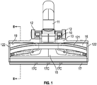
- a cleaning head in accordance with the present invention for fitting to a canister vacuum cleaner, the head comprising a body 10 and a rearwardly-extending tubular suction outlet 11 at the rear of the body 10 for releasably coupling to the distal end of a tubular wand of the cleaner.
- a motor and fan unit in a body portion of the cleaner draws air through the head via the wand.
- the head is supported at its rear by a pair of wheels 12.
- the body 10 of the head comprises a one-piece shell of moulded plastics material which defines a passageway 14 that leads from the tubular suction outlet 11 to an elongate suction mouth 15 provided on the underside of the body 10.
- the shell of the body 10 comprises an integral floor-engaging soleplate 16 on its underside.
- An aesthetic hollow plastics covering (not shown) is fitted on top of the shell.
- the suction mouth 15 extends transversely across almost the entire width of the of the soleplate 16 of the body 10 and is bounded at its front and rear by front and rear planar bottom surface portions of the soleplate 16. The front of the bottom surface of the soleplate 16 extends upwardly.
- the front edge of the suction mouth 15 is straight and extends parallel to the front edge of the bottom surface of the soleplate 16.
- the rear edge of the suction mouth 15 is curved forwardly towards its outer ends on opposite sides of a straight central portion. This shape helps to maintain a uniform air velocity across the full width of the suction mouth 15.
- a rib or lint picker 121 extends transversely of the body 10 across the rear planar bottom surface portion of the soleplate 16.
- the longitudinal profile of the rib 121 substantially follows the longitudinal profile of the rear edge of the suction mouth 15 and is separated therefrom by a region of the planar bottom surface portion of the soleplate 16.
- Respective opposite ends of the rib 121 meet a pair of side ribs 122, which extend forwardly along the side edge of the soleplate 16 to a point in front of the suction mouth 15.
- a front depending elongate floor-engaging brush 17 is mounted to a displaceable carrier plate 13 positioned above the soleplate 16.
- the tip of the brush 17 may comprise cut-outs or castellations 17C.
- the brush 17 is disposed in front of the soleplate 16.
- a rear depending elongate floor-engaging wiper 19 of elastomeric material is also mounted to the displaceable carrier plate 13.
- the wiper 19 extends through a slot formed along the rear edge of the soleplate 16.
- a rotatable actuator pedal 20 is mounted on a shaft 22 which is mounted at opposite ends to brackets 21 which extend upwardly from the soleplate 16.
- the shaft 22 has camming surfaces 23 at opposite ends which act on formations on the carrier plate 13 to displace the carrier plate 13 upwardly and downwardly as the actuator pedal 20 is rotated between two positions.
- the actuator pedal 20 is rotated into its clockwise position in which the carrier plate 13 is displaced downwardly against the spring bias to extend the elongate floor-engaging brush 17 and the elongate floor-engaging wiper 19 out of the body 10 to a position where they project below the bottom surface of the soleplate 16.
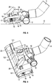
- a rotatable actuator dial 24 is mounted to the upper surface of the body 10. Rotation of the dial 24 in the counter-clockwise direction displaces the rear wheels 12 downwardly to a point where their axis of rotation extends in substantially the same plane as the bottom of the soleplate 16. Rotation of the dial 24 in the clockwise direction displaces the rear wheels 12 upwardly to a point where the bottom of the wheels lie in substantially the same plane as the bottom of the soleplate 16. In Figures 2 and 3 , the actuator dial 24 is rotated into its counter-clockwise position, so that the wheels 12 are lowered.
- the head (as configured in Figures 2 and 3 ) can be used for hard floor cleaning once the cleaner has been energised.
- the rear of the body 10 is raised by the wheels 12 and the floor-engaging members 17,19 are extended to a position below the bottom surface of the soleplate 16.
- the forwardly and downwardly inclined attitude of the body 10 makes head easier to push over the hard floor surface F being cleaned and, since the suction mouth 15 is raised above the floor surface F, any tendency for the head to adhere the floor is alleviated.
- the floor-engaging members 17,19 contact the floor surface and promote the flow of air over the underlying floor surface so that a good DPU performance is achieved for hard floors.
- the brush of the front floor-engaging member 17 acts to promote cleaning and the cut-outs 17c allow air and dust to pass under the head.
- the actuator dial 24 is rotated into its counter-clockwise position, so that the wheels 12 are lowered to raise the rear of the body 10.
- the actuator pedal 20 is rotated into its clockwise position in which the carrier plate 13 is displaced upwardly by the spring bias to retract the elongate floor-engaging brush 17 and the elongate floor-engaging wiper 19 into the body 10 above the bottom surface of the soleplate 16.
- the forwardly and downwardly inclined attitude of the body 10 again makes head easier to push over the carpet being cleaned and, since the suction mouth 15 is raised above the floor surface, any tendency for the head to adhere the carpet C is alleviated.
- the actuator dial 24 in use, for intensive carpet cleaning, is rotated into its clockwise position, so that the wheels 12 are raised to lower the rear of the body 10.
- the actuator pedal 20 is rotated into its clockwise position in which the carrier plate 13 is displaced upwardly by the spring bias to retract the elongate floor-engaging brush 17 and the elongate floor-engaging wiper 19 into the body 10 above the bottom surface of the soleplate 16.
- the entire bottom surface of the soleplate 16 and the suction mouth 15 are thus in direct contact with the carpet C and both the front and rear surfaces of the soleplate 16 act to successively bend the carpet pile away from the suction mouth 15 on successive forwards and rearwards movements of the head, so that engrained dirt and dust can be drawn out of the carpet C by the suction.
- the rib 121 augments dust removal as it penetrates, agitates and flicks engrained dust towards the surface of the carpet away from the influence of the suction.
- the head On the rearward stroke, the head is lifted slightly from the carpet by the angle of the wand and the displaced dust on the surface of the carpet C is drawn into the suction mouth 15 under the action of airflow and reduced agitation. The repeated backwards and forwards movement of the head brings more deeply embedded dust to the surface of the carpet C on successive strokes.
- the complementary shape of the rib 121 with the rear edge of the suction mouth 15 improves dust removal.
- the ribs 121 and 122 each contribute to maintaining a vacuum around the suction mouth 15.
- the present invention is simple and inexpensive in construction, yet provides a vacuum cleaner head for use on hard floors and carpet and which provides easy setting of hard floor and carpet cleaning carpet cleaning modes and unquestionable compliance with the marked energy efficiency grade of the cleaner.
Landscapes
- Engineering & Computer Science (AREA)
- Mechanical Engineering (AREA)
- Nozzles For Electric Vacuum Cleaners (AREA)
Applications Claiming Priority (1)
| Application Number | Priority Date | Filing Date | Title |
|---|---|---|---|
| CN201610694632.1A CN107752903A (zh) | 2016-08-19 | 2016-08-19 | 真空吸尘器头 |
Publications (2)
| Publication Number | Publication Date |
|---|---|
| EP3284380A1 true EP3284380A1 (de) | 2018-02-21 |
| EP3284380B1 EP3284380B1 (de) | 2021-11-03 |
Family
ID=58544276
Family Applications (1)
| Application Number | Title | Priority Date | Filing Date |
|---|---|---|---|
| EP17185183.5A Not-in-force EP3284380B1 (de) | 2016-08-19 | 2017-08-07 | Staubsaugerkopf |
Country Status (3)
| Country | Link |
|---|---|
| EP (1) | EP3284380B1 (de) |
| CN (1) | CN107752903A (de) |
| GB (1) | GB2553012B (de) |
Families Citing this family (3)
| Publication number | Priority date | Publication date | Assignee | Title |
|---|---|---|---|---|
| CN112057002A (zh) * | 2019-06-10 | 2020-12-11 | 康塔有限公司 | 地板清洁设备 |
| CN114680716B (zh) * | 2020-12-25 | 2025-11-14 | 宁波方太厨具有限公司 | 一种吸尘器 |
| CN114668338B (zh) * | 2020-12-25 | 2025-07-08 | 宁波方太厨具有限公司 | 一种清洁机 |
Citations (5)
| Publication number | Priority date | Publication date | Assignee | Title |
|---|---|---|---|---|
| EP0158145A1 (de) * | 1984-03-19 | 1985-10-16 | Matsushita Electric Industrial Co., Ltd. | Mundstück für Staubsauger |
| FR2695023A1 (fr) | 1992-08-27 | 1994-03-04 | Olivier Ets Georges | Suceur d'aspirateur à semelle protégée. |
| WO2004056252A1 (en) * | 2002-12-19 | 2004-07-08 | Koninklijke Philips Electronics N.V. | A suction attachment for a vacuum cleaner |
| DE102013106951A1 (de) * | 2013-07-02 | 2015-01-08 | Wessel-Werk Gmbh | Staubsaugerbodendüse |
| GB2528145A (en) | 2014-07-11 | 2016-01-13 | Conta Sro | Vacuum cleaner head |
Family Cites Families (4)
| Publication number | Priority date | Publication date | Assignee | Title |
|---|---|---|---|---|
| GB0023732D0 (en) * | 2000-09-28 | 2000-11-08 | Notetry Ltd | A floor tool |
| SE524125C2 (sv) * | 2002-01-22 | 2004-06-29 | Wessel Werk Gmbh | Golvmunstycke för dammsugare |
| GB2496663B (en) * | 2011-11-18 | 2014-07-30 | Dyson Technology Ltd | A cleaner head |
| CN205094326U (zh) * | 2015-10-26 | 2016-03-23 | 江苏美的清洁电器股份有限公司 | 用于吸尘器的地刷组件和吸尘器 |
-
2016
- 2016-08-19 CN CN201610694632.1A patent/CN107752903A/zh active Pending
-
2017
- 2017-02-27 GB GB1703151.9A patent/GB2553012B/en not_active Expired - Fee Related
- 2017-08-07 EP EP17185183.5A patent/EP3284380B1/de not_active Not-in-force
Patent Citations (7)
| Publication number | Priority date | Publication date | Assignee | Title |
|---|---|---|---|---|
| EP0158145A1 (de) * | 1984-03-19 | 1985-10-16 | Matsushita Electric Industrial Co., Ltd. | Mundstück für Staubsauger |
| US4638526A (en) | 1984-03-19 | 1987-01-27 | Matsushita Electric Industrial Co., Ltd. | Nozzle assembly for vacuum cleaner |
| FR2695023A1 (fr) | 1992-08-27 | 1994-03-04 | Olivier Ets Georges | Suceur d'aspirateur à semelle protégée. |
| WO2004056252A1 (en) * | 2002-12-19 | 2004-07-08 | Koninklijke Philips Electronics N.V. | A suction attachment for a vacuum cleaner |
| DE102013106951A1 (de) * | 2013-07-02 | 2015-01-08 | Wessel-Werk Gmbh | Staubsaugerbodendüse |
| GB2528145A (en) | 2014-07-11 | 2016-01-13 | Conta Sro | Vacuum cleaner head |
| EP2965678A1 (de) * | 2014-07-11 | 2016-01-13 | Conta S.R.O | Staubsaugerkopf |
Also Published As
| Publication number | Publication date |
|---|---|
| GB201703151D0 (en) | 2017-04-12 |
| EP3284380B1 (de) | 2021-11-03 |
| CN107752903A (zh) | 2018-03-06 |
| GB2553012B (en) | 2020-11-25 |
| GB2553012A (en) | 2018-02-21 |
Similar Documents
| Publication | Publication Date | Title |
|---|---|---|
| KR102080541B1 (ko) | 청소기 헤드 | |
| EP2405796B1 (de) | Kopf zur oberflächenbehandlung | |
| EP1320317B1 (de) | Bodenwerkzeug | |
| US4864682A (en) | Self-adjusting wiper strip assembly for a vacuum cleaner | |
| EP3510908B1 (de) | Zubehör für einen staubsaugersaugkopf zum sammeln von grossen schmutzpartikeln | |
| EP3494852B1 (de) | Grundplatte für einen staubsaugersaugkopf zum absaugen von feinstaub und grobem schmutz | |
| CN108289581B (zh) | 用于真空吸尘器的吸头及其操作方法 | |
| AU2001287872A1 (en) | A floor tool | |
| EP2289382A2 (de) | Staubsaugerzubehörteil | |
| US20100236019A1 (en) | Nozzle for a floor cleaning device | |
| EP3284380B1 (de) | Staubsaugerkopf | |
| EP3752037B1 (de) | Reinigungsvorrichtung | |
| EP3181029A1 (de) | Staubsaugerdüse | |
| CN110269544B (zh) | 设置有具有圆形后边缘的滑动表面的吸尘器吸嘴 | |
| CN110269545B (zh) | 设置有后刮擦肋的吸尘器吸嘴 | |
| EP3750460A1 (de) | Bodenreinigungsvorrichtung | |
| US2789308A (en) | Suction cleaning tool having resilient surface engaging fingers | |
| US11786090B2 (en) | Floor nozzle for a vacuum cleaner and vacuum cleaner | |
| EP3151711B1 (de) | Saugdüse mit drei einstellungen | |
| EP1252852A2 (de) | Saugkopf für Bodenstaubsauger | |
| JP5681776B1 (ja) | 吸込ヘッド及び電気掃除機 | |
| EP4523588A1 (de) | Düse für einen staubsauger und staubsauger mit einer solchen düse | |
| HK40010127A (en) | Base plate for a vacuum cleaner suction head for the suction of fine dust and large debris | |
| JP2024166001A (ja) | 電気掃除機の吸込口 | |
| JP2010252981A (ja) | 吸込口体および電気掃除機 |
Legal Events
| Date | Code | Title | Description |
|---|---|---|---|
| PUAI | Public reference made under article 153(3) epc to a published international application that has entered the european phase |
Free format text: ORIGINAL CODE: 0009012 |
|
| STAA | Information on the status of an ep patent application or granted ep patent |
Free format text: STATUS: THE APPLICATION HAS BEEN PUBLISHED |
|
| AK | Designated contracting states |
Kind code of ref document: A1 Designated state(s): AL AT BE BG CH CY CZ DE DK EE ES FI FR GB GR HR HU IE IS IT LI LT LU LV MC MK MT NL NO PL PT RO RS SE SI SK SM TR |
|
| AX | Request for extension of the european patent |
Extension state: BA ME |
|
| STAA | Information on the status of an ep patent application or granted ep patent |
Free format text: STATUS: REQUEST FOR EXAMINATION WAS MADE |
|
| 17P | Request for examination filed |
Effective date: 20180314 |
|
| RBV | Designated contracting states (corrected) |
Designated state(s): AL AT BE BG CH CY CZ DE DK EE ES FI FR GB GR HR HU IE IS IT LI LT LU LV MC MK MT NL NO PL PT RO RS SE SI SK SM TR |
|
| GRAP | Despatch of communication of intention to grant a patent |
Free format text: ORIGINAL CODE: EPIDOSNIGR1 |
|
| STAA | Information on the status of an ep patent application or granted ep patent |
Free format text: STATUS: GRANT OF PATENT IS INTENDED |
|
| INTG | Intention to grant announced |
Effective date: 20210520 |
|
| GRAS | Grant fee paid |
Free format text: ORIGINAL CODE: EPIDOSNIGR3 |
|
| GRAA | (expected) grant |
Free format text: ORIGINAL CODE: 0009210 |
|
| STAA | Information on the status of an ep patent application or granted ep patent |
Free format text: STATUS: THE PATENT HAS BEEN GRANTED |
|
| RBV | Designated contracting states (corrected) |
Designated state(s): AL AT BE BG CH CY CZ DE DK EE ES FI FR GR HR HU IE IS IT LI LT LU LV MC MK MT NL NO PL PT RO RS SE SI SK SM TR |
|
| RAP1 | Party data changed (applicant data changed or rights of an application transferred) |
Owner name: CANDY HOOVER (SUZHOU) CO. LTD. |
|
| AK | Designated contracting states |
Kind code of ref document: B1 Designated state(s): AL AT BE BG CH CY CZ DE DK EE ES FI FR GR HR HU IE IS IT LI LT LU LV MC MK MT NL NO PL PT RO RS SE SI SK SM TR |
|
| REG | Reference to a national code |
Ref country code: AT Ref legal event code: REF Ref document number: 1443216 Country of ref document: AT Kind code of ref document: T Effective date: 20211115 Ref country code: CH Ref legal event code: EP |
|
| REG | Reference to a national code |
Ref country code: DE Ref legal event code: R096 Ref document number: 602017048608 Country of ref document: DE |
|
| REG | Reference to a national code |
Ref country code: IE Ref legal event code: FG4D |
|
| REG | Reference to a national code |
Ref country code: LT Ref legal event code: MG9D |
|
| REG | Reference to a national code |
Ref country code: NL Ref legal event code: MP Effective date: 20211103 |
|
| REG | Reference to a national code |
Ref country code: AT Ref legal event code: MK05 Ref document number: 1443216 Country of ref document: AT Kind code of ref document: T Effective date: 20211103 |
|
| PG25 | Lapsed in a contracting state [announced via postgrant information from national office to epo] |
Ref country code: RS Free format text: LAPSE BECAUSE OF FAILURE TO SUBMIT A TRANSLATION OF THE DESCRIPTION OR TO PAY THE FEE WITHIN THE PRESCRIBED TIME-LIMIT Effective date: 20211103 Ref country code: LT Free format text: LAPSE BECAUSE OF FAILURE TO SUBMIT A TRANSLATION OF THE DESCRIPTION OR TO PAY THE FEE WITHIN THE PRESCRIBED TIME-LIMIT Effective date: 20211103 Ref country code: FI Free format text: LAPSE BECAUSE OF FAILURE TO SUBMIT A TRANSLATION OF THE DESCRIPTION OR TO PAY THE FEE WITHIN THE PRESCRIBED TIME-LIMIT Effective date: 20211103 Ref country code: BG Free format text: LAPSE BECAUSE OF FAILURE TO SUBMIT A TRANSLATION OF THE DESCRIPTION OR TO PAY THE FEE WITHIN THE PRESCRIBED TIME-LIMIT Effective date: 20220203 Ref country code: AT Free format text: LAPSE BECAUSE OF FAILURE TO SUBMIT A TRANSLATION OF THE DESCRIPTION OR TO PAY THE FEE WITHIN THE PRESCRIBED TIME-LIMIT Effective date: 20211103 |
|
| PG25 | Lapsed in a contracting state [announced via postgrant information from national office to epo] |
Ref country code: IS Free format text: LAPSE BECAUSE OF FAILURE TO SUBMIT A TRANSLATION OF THE DESCRIPTION OR TO PAY THE FEE WITHIN THE PRESCRIBED TIME-LIMIT Effective date: 20220303 Ref country code: SE Free format text: LAPSE BECAUSE OF FAILURE TO SUBMIT A TRANSLATION OF THE DESCRIPTION OR TO PAY THE FEE WITHIN THE PRESCRIBED TIME-LIMIT Effective date: 20211103 Ref country code: PT Free format text: LAPSE BECAUSE OF FAILURE TO SUBMIT A TRANSLATION OF THE DESCRIPTION OR TO PAY THE FEE WITHIN THE PRESCRIBED TIME-LIMIT Effective date: 20220303 Ref country code: PL Free format text: LAPSE BECAUSE OF FAILURE TO SUBMIT A TRANSLATION OF THE DESCRIPTION OR TO PAY THE FEE WITHIN THE PRESCRIBED TIME-LIMIT Effective date: 20211103 Ref country code: NO Free format text: LAPSE BECAUSE OF FAILURE TO SUBMIT A TRANSLATION OF THE DESCRIPTION OR TO PAY THE FEE WITHIN THE PRESCRIBED TIME-LIMIT Effective date: 20220203 Ref country code: NL Free format text: LAPSE BECAUSE OF FAILURE TO SUBMIT A TRANSLATION OF THE DESCRIPTION OR TO PAY THE FEE WITHIN THE PRESCRIBED TIME-LIMIT Effective date: 20211103 Ref country code: LV Free format text: LAPSE BECAUSE OF FAILURE TO SUBMIT A TRANSLATION OF THE DESCRIPTION OR TO PAY THE FEE WITHIN THE PRESCRIBED TIME-LIMIT Effective date: 20211103 Ref country code: HR Free format text: LAPSE BECAUSE OF FAILURE TO SUBMIT A TRANSLATION OF THE DESCRIPTION OR TO PAY THE FEE WITHIN THE PRESCRIBED TIME-LIMIT Effective date: 20211103 Ref country code: GR Free format text: LAPSE BECAUSE OF FAILURE TO SUBMIT A TRANSLATION OF THE DESCRIPTION OR TO PAY THE FEE WITHIN THE PRESCRIBED TIME-LIMIT Effective date: 20220204 Ref country code: ES Free format text: LAPSE BECAUSE OF FAILURE TO SUBMIT A TRANSLATION OF THE DESCRIPTION OR TO PAY THE FEE WITHIN THE PRESCRIBED TIME-LIMIT Effective date: 20211103 |
|
| PG25 | Lapsed in a contracting state [announced via postgrant information from national office to epo] |
Ref country code: SM Free format text: LAPSE BECAUSE OF FAILURE TO SUBMIT A TRANSLATION OF THE DESCRIPTION OR TO PAY THE FEE WITHIN THE PRESCRIBED TIME-LIMIT Effective date: 20211103 Ref country code: SK Free format text: LAPSE BECAUSE OF FAILURE TO SUBMIT A TRANSLATION OF THE DESCRIPTION OR TO PAY THE FEE WITHIN THE PRESCRIBED TIME-LIMIT Effective date: 20211103 Ref country code: RO Free format text: LAPSE BECAUSE OF FAILURE TO SUBMIT A TRANSLATION OF THE DESCRIPTION OR TO PAY THE FEE WITHIN THE PRESCRIBED TIME-LIMIT Effective date: 20211103 Ref country code: EE Free format text: LAPSE BECAUSE OF FAILURE TO SUBMIT A TRANSLATION OF THE DESCRIPTION OR TO PAY THE FEE WITHIN THE PRESCRIBED TIME-LIMIT Effective date: 20211103 Ref country code: DK Free format text: LAPSE BECAUSE OF FAILURE TO SUBMIT A TRANSLATION OF THE DESCRIPTION OR TO PAY THE FEE WITHIN THE PRESCRIBED TIME-LIMIT Effective date: 20211103 Ref country code: CZ Free format text: LAPSE BECAUSE OF FAILURE TO SUBMIT A TRANSLATION OF THE DESCRIPTION OR TO PAY THE FEE WITHIN THE PRESCRIBED TIME-LIMIT Effective date: 20211103 |
|
| REG | Reference to a national code |
Ref country code: DE Ref legal event code: R097 Ref document number: 602017048608 Country of ref document: DE |
|
| PLBE | No opposition filed within time limit |
Free format text: ORIGINAL CODE: 0009261 |
|
| STAA | Information on the status of an ep patent application or granted ep patent |
Free format text: STATUS: NO OPPOSITION FILED WITHIN TIME LIMIT |
|
| 26N | No opposition filed |
Effective date: 20220804 |
|
| PG25 | Lapsed in a contracting state [announced via postgrant information from national office to epo] |
Ref country code: AL Free format text: LAPSE BECAUSE OF FAILURE TO SUBMIT A TRANSLATION OF THE DESCRIPTION OR TO PAY THE FEE WITHIN THE PRESCRIBED TIME-LIMIT Effective date: 20211103 |
|
| PG25 | Lapsed in a contracting state [announced via postgrant information from national office to epo] |
Ref country code: SI Free format text: LAPSE BECAUSE OF FAILURE TO SUBMIT A TRANSLATION OF THE DESCRIPTION OR TO PAY THE FEE WITHIN THE PRESCRIBED TIME-LIMIT Effective date: 20211103 |
|
| REG | Reference to a national code |
Ref country code: DE Ref legal event code: R119 Ref document number: 602017048608 Country of ref document: DE |
|
| PG25 | Lapsed in a contracting state [announced via postgrant information from national office to epo] |
Ref country code: MC Free format text: LAPSE BECAUSE OF FAILURE TO SUBMIT A TRANSLATION OF THE DESCRIPTION OR TO PAY THE FEE WITHIN THE PRESCRIBED TIME-LIMIT Effective date: 20211103 |
|
| REG | Reference to a national code |
Ref country code: CH Ref legal event code: PL |
|
| PG25 | Lapsed in a contracting state [announced via postgrant information from national office to epo] |
Ref country code: LU Free format text: LAPSE BECAUSE OF NON-PAYMENT OF DUE FEES Effective date: 20220807 Ref country code: LI Free format text: LAPSE BECAUSE OF NON-PAYMENT OF DUE FEES Effective date: 20220831 Ref country code: CH Free format text: LAPSE BECAUSE OF NON-PAYMENT OF DUE FEES Effective date: 20220831 |
|
| REG | Reference to a national code |
Ref country code: BE Ref legal event code: MM Effective date: 20220831 |
|
| PG25 | Lapsed in a contracting state [announced via postgrant information from national office to epo] |
Ref country code: IT Free format text: LAPSE BECAUSE OF FAILURE TO SUBMIT A TRANSLATION OF THE DESCRIPTION OR TO PAY THE FEE WITHIN THE PRESCRIBED TIME-LIMIT Effective date: 20211103 |
|
| PG25 | Lapsed in a contracting state [announced via postgrant information from national office to epo] |
Ref country code: IE Free format text: LAPSE BECAUSE OF NON-PAYMENT OF DUE FEES Effective date: 20220807 Ref country code: FR Free format text: LAPSE BECAUSE OF NON-PAYMENT OF DUE FEES Effective date: 20220831 Ref country code: DE Free format text: LAPSE BECAUSE OF NON-PAYMENT OF DUE FEES Effective date: 20230301 |
|
| PG25 | Lapsed in a contracting state [announced via postgrant information from national office to epo] |
Ref country code: BE Free format text: LAPSE BECAUSE OF NON-PAYMENT OF DUE FEES Effective date: 20220831 |
|
| PG25 | Lapsed in a contracting state [announced via postgrant information from national office to epo] |
Ref country code: HU Free format text: LAPSE BECAUSE OF FAILURE TO SUBMIT A TRANSLATION OF THE DESCRIPTION OR TO PAY THE FEE WITHIN THE PRESCRIBED TIME-LIMIT; INVALID AB INITIO Effective date: 20170807 |
|
| PG25 | Lapsed in a contracting state [announced via postgrant information from national office to epo] |
Ref country code: CY Free format text: LAPSE BECAUSE OF FAILURE TO SUBMIT A TRANSLATION OF THE DESCRIPTION OR TO PAY THE FEE WITHIN THE PRESCRIBED TIME-LIMIT Effective date: 20211103 |
|
| PG25 | Lapsed in a contracting state [announced via postgrant information from national office to epo] |
Ref country code: MK Free format text: LAPSE BECAUSE OF FAILURE TO SUBMIT A TRANSLATION OF THE DESCRIPTION OR TO PAY THE FEE WITHIN THE PRESCRIBED TIME-LIMIT Effective date: 20211103 |
|
| PG25 | Lapsed in a contracting state [announced via postgrant information from national office to epo] |
Ref country code: TR Free format text: LAPSE BECAUSE OF FAILURE TO SUBMIT A TRANSLATION OF THE DESCRIPTION OR TO PAY THE FEE WITHIN THE PRESCRIBED TIME-LIMIT Effective date: 20211103 |
|
| PG25 | Lapsed in a contracting state [announced via postgrant information from national office to epo] |
Ref country code: MT Free format text: LAPSE BECAUSE OF FAILURE TO SUBMIT A TRANSLATION OF THE DESCRIPTION OR TO PAY THE FEE WITHIN THE PRESCRIBED TIME-LIMIT Effective date: 20211103 |