EP3284872A1 - Dichtelement zum anschliessen einer trockenbauwand - Google Patents
Dichtelement zum anschliessen einer trockenbauwand Download PDFInfo
- Publication number
- EP3284872A1 EP3284872A1 EP16184658.9A EP16184658A EP3284872A1 EP 3284872 A1 EP3284872 A1 EP 3284872A1 EP 16184658 A EP16184658 A EP 16184658A EP 3284872 A1 EP3284872 A1 EP 3284872A1
- Authority
- EP
- European Patent Office
- Prior art keywords
- sealing element
- drywall
- edge
- step structure
- component
- Prior art date
- Legal status (The legal status is an assumption and is not a legal conclusion. Google has not performed a legal analysis and makes no representation as to the accuracy of the status listed.)
- Withdrawn
Links
Images


Classifications
-
- E—FIXED CONSTRUCTIONS
- E04—BUILDING
- E04B—GENERAL BUILDING CONSTRUCTIONS; WALLS, e.g. PARTITIONS; ROOFS; FLOORS; CEILINGS; INSULATION OR OTHER PROTECTION OF BUILDINGS
- E04B2/00—Walls, e.g. partitions, for buildings; Wall construction with regard to insulation; Connections specially adapted to walls
- E04B2/74—Removable non-load-bearing partitions; Partitions with a free upper edge
- E04B2/7407—Removable non-load-bearing partitions; Partitions with a free upper edge assembled using frames with infill panels or coverings only; made-up of panels and a support structure incorporating posts
- E04B2/7409—Removable non-load-bearing partitions; Partitions with a free upper edge assembled using frames with infill panels or coverings only; made-up of panels and a support structure incorporating posts special measures for sound or thermal insulation, including fire protection
- E04B2/7411—Details for fire protection
-
- E—FIXED CONSTRUCTIONS
- E04—BUILDING
- E04B—GENERAL BUILDING CONSTRUCTIONS; WALLS, e.g. PARTITIONS; ROOFS; FLOORS; CEILINGS; INSULATION OR OTHER PROTECTION OF BUILDINGS
- E04B2/00—Walls, e.g. partitions, for buildings; Wall construction with regard to insulation; Connections specially adapted to walls
- E04B2/74—Removable non-load-bearing partitions; Partitions with a free upper edge
- E04B2/7407—Removable non-load-bearing partitions; Partitions with a free upper edge assembled using frames with infill panels or coverings only; made-up of panels and a support structure incorporating posts
- E04B2/7453—Removable non-load-bearing partitions; Partitions with a free upper edge assembled using frames with infill panels or coverings only; made-up of panels and a support structure incorporating posts with panels and support posts, extending from floor to ceiling
- E04B2/7457—Removable non-load-bearing partitions; Partitions with a free upper edge assembled using frames with infill panels or coverings only; made-up of panels and a support structure incorporating posts with panels and support posts, extending from floor to ceiling with wallboards attached to the outer faces of the posts, parallel to the partition
-
- E—FIXED CONSTRUCTIONS
- E04—BUILDING
- E04B—GENERAL BUILDING CONSTRUCTIONS; WALLS, e.g. PARTITIONS; ROOFS; FLOORS; CEILINGS; INSULATION OR OTHER PROTECTION OF BUILDINGS
- E04B2/00—Walls, e.g. partitions, for buildings; Wall construction with regard to insulation; Connections specially adapted to walls
- E04B2/74—Removable non-load-bearing partitions; Partitions with a free upper edge
- E04B2/82—Removable non-load-bearing partitions; Partitions with a free upper edge characterised by the manner in which edges are connected to the building; Means therefor; Special details of easily-removable partitions as far as related to the connection with other parts of the building
- E04B2/825—Removable non-load-bearing partitions; Partitions with a free upper edge characterised by the manner in which edges are connected to the building; Means therefor; Special details of easily-removable partitions as far as related to the connection with other parts of the building the connection between the floor and the ceiling being achieved without any restraining forces acting in the plane of the partition
Definitions
- the invention relates to drywall and the installation of drywall. Furthermore, the present invention relates to measures for tightly connecting a drywall to an uneven or profiled component.
- Drywall panels usually have a rectangular cross-section. In the assembly of drywall panels to components with uneven connection surface it comes thus in addition to the drywall to passages, especially on the ceiling, which must be closed for sound insulation and fire protection.
- metal ceilings are common, which have a trapezoidal profile with elongated struts and depressions, which are wave-shaped.
- a trapezoidal sheet has in cross section trapezoidally folded profile sheets.
- the ability to adapt the drywall according to the profile of the unevenness of the component to which the drywall is to be connected by means of a saw is very labor intensive, and due to the inaccuracies of the blank, the remaining gaps between the component and the drywall must be with sealant or gypsum be filled out.
- CA 2841523 A1 is a sealing element for sealing through holes when attaching the drywall to a profiled component, such as a metal ceiling with trapezoidal profile, known to seal the passages an upper insulating insert, which is inserted into the passages, and a lower insulating insert, the flat on a Edge portion of the drywall rests, has.
- a profiled component such as a metal ceiling with trapezoidal profile
- Mold plates for sealing passages between a profiled building component and a drywall are shown, which are placed on the edge region of the drywall and engage in the profile of the building component and this seals.
- the mold plates may be formed of a fire-resistant material.
- the assembly of the mold plates is complex, however, since various individual components must be installed together on site.
- a sealing element for connecting a drywall to a component wherein the sealing element is formed as a planar component, wherein a first edge is provided with a step structure in the thickness direction and an opposite second edge is provided with a contour in the width direction, the corresponds to a profile of the device.
- An idea of the above sealing element is that it is flat to the attachment to a drywall and formed at one edge has a contour which engages the contour of the connection line between the drywall and the building component to between the drywall and the building element existing through holes close.
- the second edge can be provided with a sealing strip, which in particular has intumescent or slowly burn-off elastic material.
- the sealing strip seals when inserting the sealing element on the building component from the connection area between the sealing element and the building component. In this way, a subsequent closing with a sealant or a subsequent filling of a gap between the sealing element and the building component can be avoided.
- the first edge can be provided with a further sealing strip which in particular has intumescent or slowly burn-off elastic material.
- a surface side of the sealing element may be provided with a protective layer, which in particular comprises a porous material.
- a protective layer which in particular comprises a porous material. This serves to ensure a relative mobility of the sealing element, if they are placed on one or more screw heads of fastening screws. During a movement, the screw head mills into the porous protective layer and sets the relative movement less resistance than would be the case when digging into the material of the sealing element.
- cover plate which projects beyond the step structure of the first edge at least partially.
- the cover plate enables improved protection of a movement joint formed in the region of the step structure.
- an arrangement with the above sealing element and a drywall is provided, which is arranged on a component, wherein the drywall has at least one drywall having a corresponding to the step structure of the first edge of the sealing element step structure, which interlock, the a movement joint is formed to receive a relative movement between the sealing element and the drywall.
- a cover plate is provided on the sealing element, which covers a movement joint between the step structure of the first edge of the sealing element and the corresponding step structure of the drywall.
- the drywall is held on a held by a holding profile stand with a fastening screw, wherein a surface side of the sealing element is provided with a protective layer, which in particular comprises a porous material, wherein a screw head of the fastening screw is received in the protective layer and milled in a relative movement between the drywall and the sealing element in the protective layer.
- a protective layer which in particular comprises a porous material
- the edge can be provided with the step structure of the sealing element with a sealing strip.
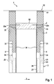
- FIGS. 1 and 2 an arrangement is shown in which a drywall 2 is connected or attached to a building component 1, such as a building ceiling or the like, by means of a sealing element 3.
- FIG. 1 shows a cross-sectional view along a longitudinally extending building component 1
- FIG. 2 shows a front view of the terminal portion of the drywall 2 to the building component. 1
- the building component 1 may be a building wall or a building ceiling and be provided with a structure, so that the connection region of the drywall 2 to the building component 1 is not rectilinear but uneven.
- trapezoidal structure of the building component 1 corresponds to a common structure in metal ceilings, which is provided to increase the carrying capacity with a trapezoidal profile (trapezoidal sheet metal roof).
- the projecting longitudinal struts formed by the trapezoidal profile extend in a longitudinal direction L.
- a drywall 2 is connected to the building component 1 so that the best possible seal against sound and combustion gases is achieved.
- the drywall 2 is provided with a stand 21 which can extend between two building elements 1 and ensures a secure state of the drywall 2.
- the stand 21 is mounted on the building component 1 with the aid of a holding profile 22, wherein the holding profile 22 is substantially U-shaped and receives the stand 21 between legs 22s of the holding profile 22s such that a relative movement between the building component 1 and the stand 21st in the extension direction of the legs 22s can be accommodated by moving the stator 21 in the holding profile 22.
- drywall panels 23 formed, for example, of a fire resistant plasterboard or the like, e.g. be applied by screws.
- the drywall panels 23 may be arranged on both sides of the stator 21. At the building component 1 facing edge of the drywall panels 23, these may be provided with a step structure 24 or be mounted in two layers.
- a sealing element 3 may be arranged, as for example in FIG FIG. 3 is shown in perspective.
- the sealing element 3 is formed as a flat component, in particular with a thickness which substantially corresponds to the thickness of the drywall plate 23.
- the sealing element 3 may be provided at a first edge with a stepped structure 31 corresponding to the step structure of the drywall 23, which is designed to engage in the assembled state in the step structure 24 of the drywall 23, in particular so that the outwardly facing surfaces substantially lie in one plane.
- the width of the sealing element 3 should be selected so that the step structures 24, 31 form a movement joint, which allows the drywall plate 23 and the sealing element 3 can move against each other.
- the material of the sealing element 3 is preferably a mineral building material, in particular a fire-resistant material.
- the stepped structure 31 of the sealing element 3 may be formed, for example, by an outer side 35 is set back relative to an inner side 36 and the corresponding step structure of the drywall 23 is formed accordingly by an inner side 26 is set back relative to an outer side 25.
- the sealing element 3 has a contour, ie a deviation from a rectilinear extent, on a second edge 32 opposite the step 31, which corresponds to the contour of the profile of the building component 1, as shown in FIG FIG. 2 is shown.
- the contoured edge 32 of the Inserted sealing element 3 in the profile of the building component 1 and then fastened by means of fastening screws 4 to the support section 22.
- the contoured edge 32 may be provided with a sealing strip 33, which serves to achieve a good seal when attaching the sealing element 3 to the profile of the building component 1.
- the sealing strip 33 may be formed from an intumescent or a slow-burning elastic material to achieve an improved seal against the passage of fumes between the drywall wall 2 and the building component 1 in case of fire.
- a cover plate 5 may be provided, which may be formed of a metal material or of a mineral building material.
- the cover plate 5 is attached either to the sealing element 3 or the drywall plate 23 and abuts on an outer side of the drywall 23 and on an outer side of the sealing element 3 and can slide along the building component 1 or on the drywall wall 2 in a relative movement.
- one or more of the edges of the gradation 31 may be provided with an intumescent or slowly burnable elastic further sealing strip 34, so that the movement joint is closed in case of fire and thus the weak point of the movement joint is reliably closed.
- FIG. 5 shows for a further embodiment, the attachment between the retaining profile 22 and the stator 21 by means of connecting screws 60 which can move in longitudinal grooves of the stator 21 in the arrangement direction of the legs 22s.
- the side facing the stator 21 of the sealing element 3 may be provided with a protective layer 37 which may be formed as a porous layer into which the screw head 61 of Connecting screw 60 dig or can mill without damaging the material of the sealing element 3.
- the thickness of the sealing member 3 including the protective layer 37 is preferably selected according to the thickness of the drywall plate 23. In this way, it is possible to use conventional drywall panels 23 to construct a drywall 2 and to enable the drywall 2 to be tightly assembled without the use of additional sealants.
- the sealing strip 33 as in the embodiment of the FIG. 5 shown having a shape or contour that allows an improved concern with a profile of the device.
- the contour may include a skew in the thickness direction of the sealing element 3.
- sealing element 3 Another installation possibility of the sealing element 3 is given with a single-layer wall, with an additional protective strip is placed over the resulting movement joint.
Landscapes
- Engineering & Computer Science (AREA)
- Architecture (AREA)
- Physics & Mathematics (AREA)
- Electromagnetism (AREA)
- Civil Engineering (AREA)
- Structural Engineering (AREA)
- Building Environments (AREA)
Abstract
Die Erfindung betrifft ein Dichtelement (3) zum Anschluss einer Trockenbauwand (2) an ein Bauelement (1), wobei das Dichtelement (3) als flächiges Bauteil ausgebildet ist, wobei eine erste Kante mit einer Stufenstruktur (24) in Dickenrichtung versehen ist und eine gegenüberliegende zweite Kante mit einer Kontur in Breitenrichtung versehen ist, die mit einem Profil des Bauelements (1) korrespondiert.
Description
- Die Erfindung betrifft Trockenbauwände und die Montage von Trockenbauwänden. Weiterhin betrifft die vorliegende Erfindung Maßnahmen zum dichten Anschließen einer Trockenbauwand an ein unebenes bzw. mit einem Profil versehenen Bauelement.
- Trockenbauplatten weisen in der Regel einen rechteckigen Querschnitt auf. Bei der Montage von Trockenbauplatten an Bauelementen mit unebener Anschlussfläche kommt es somit neben der Trockenbauwand zu Durchlässen, insbesondere an der Decke, die aus Gründen des Schallschutzes und des Brandschutzes verschlossen werden müssen.
- Beispielsweise sind Metalldecken üblich, die ein trapezförmiges Profil mit länglichen Streben und Vertiefungen, die wellenförmig ausgebildet sind, aufweisen. Ein solches Trapezblech(dach) weist im Querschnitt trapezähnlich gekantete Profilbleche auf. Das Anbringen von Trockenbauwänden quer zu den längs verlaufenden Streben kommt es zu Durchgangsöffnungen zwischen der Metalldecke und der Trockenbauwand. Die Möglichkeit, die Trockenbauwand entsprechend dem Profil der Unebenheit des Bauelements, an das die Trockenbauwand angeschlossen werden soll, mit Hilfe einer Säge anzupassen, ist sehr arbeitsaufwändig, und aufgrund der Ungenauigkeiten des Zuschnitts müssen die verbleibenden Spalte zwischen dem Bauelement und der Trockenbauwand mit Dichtmasse oder Gips ausgespachtelt werden.
- Aus der Druckschrift
CA 2841523 A1 ist ein Dichtelement zum Abdichten von Durchgangsöffnungen beim Anbringen der Trockenbauwand an ein profiliertes Bauelement, wie beispielsweise einer Metalldecke mit Trapezprofil, bekannt, das zur Abdichtung der Durchgänge einen oberen Isolierungseinsatz, der in die Durchgänge eingeschoben wird, und einen unteren Isolierungseinsatz, der flächig an einem Randabschnitt der Trockenbauwand anliegt, aufweist. - Die Druckschrift
US 8,074,412 B1 zeigt ein Einsatzelement zum Anbringen zwischen den profilierten Gebäudebauelementen und einer Trockenbauwand, wobei das Einsatzelement ein dem Gebäudebauelement entsprechendes Profil aufweist, so dass die Trockenbauwand dicht mit dem Gebäudebauelement verbunden werden kann. - Aus der Druckschrift
US 2007/175140 A1 sind Formplatten zum Abdichten von Durchgängen zwischen einem profilierten Gebäudebauelement und einer Trockenbauwand gezeigt, die an den Randbereich der Trockenbauplatte aufgesetzt werden und in das Profil des Gebäudebauelements eingreifen und dieses dadurch abdichtet. Die Formplatten können aus einem feuerbeständigen Material ausgebildet sein. Die Montage der Formplatten ist jedoch aufwändig, da verschiedene Einzelkomponenten vor Ort gemeinsam installiert werden müssen. - Es ist Aufgabe der vorliegenden Erfindung, ein Dichtelement zum Abdichten von Durchgängen zwischen einem Gebäudebauelement und einer Trockenbauwand zur Verfügung zu stellen, das einfach montierbar ist, Relativbewegungen zwischen der Trockenbauwand und dem Gebäudebauelement aufnehmen kann und eine gute Brandschutz- und Schallschutzfunktion bereitstellt.
- Diese Aufgabe wird durch das Dichtelement zum Anschließen einer Trockenbauwand an ein Bauelement, insbesondere mit einer profilierten Anschlussfläche gemäß Anspruch 1, sowie durch die Anordnung gemäß dem nebengeordneten Anspruch gelöst.
- Weitere Ausgestaltungen sind in den abhängigen Ansprüchen angegeben.
- Gemäß einem ersten Aspekt ist ein Dichtelement zum Anschluss einer Trockenbauwand an ein Bauelement vorgesehen, wobei das Dichtelement als flächiges Bauteil ausgebildet ist, wobei eine erste Kante mit einer Stufenstruktur in Dickenrichtung versehen ist und eine gegenüberliegende zweite Kante mit einer Kontur in Breitenrichtung versehen ist, die mit einem Profil des Bauelements korrespondiert.
- Eine Idee des obigen Dichtelementes besteht darin, dass es flächig zum Aufsatz auf eine Trockenbauwand ausgebildet ist und an einer Kante eine Kontur aufweist, die in die Kontur der Anschlusslinie zwischen der Trockenbauwand und dem Gebäudebauelement eingreift, um zwischen der Trockenbauwand und dem Gebäudeelement bestehende Durchgangsöffnungen zu verschließen.
- Weiterhin kann die zweite Kante mit einem Dichtungsstreifen versehen sein, der insbesondere intumeszierendes oder langsam abbrennbares elastisches Material aufweist. Der Dichtungsstreifen dichtet beim Einsetzen des Dichtelementes auf das Gebäudebauelement den Anschlussbereich zwischen dem Dichtelement und dem Gebäudebauelement ab. Auf diese Weise kann ein nachträgliches Verschließen mit einer Dichtmasse oder ein nachträgliches Verspachteln eines Zwischenraums zwischen dem Dichtelement und dem Gebäudebauelement vermieden werden.
- Die erste Kante kann mit einem weiteren Dichtungsstreifen versehen sein, der insbesondere intumeszierendes oder langsam abbrennbares elastisches Material aufweist.
- Insbesondere kann eine Flächenseite des Dichtelements mit einer Schutzschicht versehen sein, die insbesondere ein poröses Material aufweist. Dies dient dazu eine relative Beweglichkeit des Dichtelements sicherzustellen, wenn diese auf einem oder mehreren Schraubenköpfen von Befestigungsschrauben aufgesetzt sind. Bei einer Bewegung fräst sich der Schraubenkopf in die poröse Schutzschicht ein und setzt der relativen Bewegung einen geringeren Widerstand entgegen als dies beim Eingraben in das Material des Dichtelements der Fall wäre.
- Es kann eine Abdeckplatte vorgesehen sein, die die Stufenstruktur der ersten Kante zumindest teilweise überragt. Die Abdeckplatte ermöglicht einen verbesserten Schutz einer im Bereich der Stufenstruktur ausgebildeten Bewegungsfuge.
- Gemäß einem weiteren Aspekt ist eine Anordnung mit dem obigen Dichtelement und einer Trockenbauwand vorgesehen, die an einem Bauelement angeordnet ist, wobei die Trockenbauwand mindestens eine Trockenbauplatte aufweist, die mit einer zur Stufenstruktur der ersten Kante des Dichtelements korrespondierende Stufenstruktur aufweist, die so ineinandergreifen, das eine Bewegungsfuge ausgebildet wird, um eine Relativbewegung zwischen dem Dichtelement und der Trockenbauplatte aufzunehmen.
- Weiterhin kann eine Abdeckplatte an dem Dichtelement vorgesehen ist, die eine Bewegungsfuge zwischen der Stufenstruktur der ersten Kante des Dichtelements und der korrespondierenden Stufenstruktur der Trockenbauplatte überdeckt.
- Es kann vorgesehen sein, dass die Trockenbauplatte an einem durch ein Halteprofil gehaltenen Ständer mit einer Befestigungsschraube gehalten ist, wobei eine Flächenseite des Dichtelements mit einer Schutzschicht versehen ist, die insbesondere ein poröses Material aufweist, wobei ein Schraubenkopf der Befestigungsschraube in der Schutzschicht aufgenommen wird und sich bei einer Relativbewegung zwischen der Trockenbauplatte und dem Dichtelement in die Schutzschicht einfräst.
- Weiterhin kann die Kante mit der Stufenstruktur des Dichtelements mit einem Dichtungsstreifen versehen sein.
- Ausführungsformen werden nachfolgend anhand der beigefügten Zeichnungen näher erläutert. Es zeigen:
- Figur 1
- eine Querschnittsdarstellung durch eine Trockenbauwand, die quer zu Längsstreben eines profilierten Gebäudebauelements verläuft;
- Figur 2
- eine Vorderansicht auf eine Seite der Trockenbauwand mit einem Dichtelement, die quer zur Längserstreckung von Längsstreben eines Gebäudebauelements mit trapezförmigem Profil verläuft;
- Figur 3
- eine perspektivische Darstellung eines Dichtelements zum Abdichten eines Anschlusses zwischen einer Trockenbauwand und einem Gebäudebauelement;
- Figur 4
- eine weitere Ausführungsform des Dichtelements;
- Figur 5
- eine Querschnittsdarstellung durch eine weitere Trockenbauwand.
- In den
Figuren 1 und2 ist eine Anordnung gezeigt, bei der eine Trockenbauwand 2 an ein Gebäudebauelement 1, wie z.B. einer Gebäudedecke oder dergleichen, mit Hilfe eines Dichtelementes 3 angeschlossen bzw. angebracht ist. -
Figur 1 zeigt eine Querschnittsdarstellung längs eines sich länglich erstreckenden Gebäudebauelements 1, undFigur 2 zeigt eine Vorderansicht auf den Anschlussbereich der Trockenbauwand 2 an das Gebäudebauelement 1. - Das Gebäudebauelement 1 kann eine Gebäudewand oder eine Gebäudedecke sein und mit einer Struktur versehen sein, so dass der Anschlussbereich der Trockenbauwand 2 an das Gebäudebauelement 1 nicht geradlinig sondern uneben verläuft. Die in
Figur 2 beispielhaft dargestellte Trapezstruktur des Gebäudebauelements 1 entspricht einer gängigen Struktur bei Metalldecken, die zur Erhöhung der Tragfähigkeit mit einem trapezförmigen Profil versehen ist (Trapezblechdach). Dabei erstrecken sich die durch das trapezförmige Profil ausgebildete vorstehende Längsstreben in einer Längsrichtung L. - Eine Trockenbauwand 2 ist an das Gebäudebauelement 1 so angeschlossen, dass ein möglichst dichter Abschluss gegenüber Schall und Brandgasen erreicht wird. Dazu ist die Trockenbauwand 2 mit einem Ständer 21 vorgesehen, der sich zwischen zwei Gebäudebauelementen 1 erstrecken kann und für einen sicheren Stand der Trockenbauwand 2 sorgt. Der Ständer 21 wird mit Hilfe eines Halteprofils 22 an dem Gebäudebauelement 1 angebracht, wobei das Halteprofil 22 im Wesentlichen U-förmig ausgebildet ist und zwischen Schenkeln 22s des Halteprofils 22s den Ständer 21 so aufnimmt, dass eine Relativbewegung zwischen dem Gebäudebauelement 1 und dem Ständer 21 in Erstreckungsrichtung der Schenkel 22s durch Verschieben des Ständers 21 in dem Halteprofil 22 aufgenommen werden kann.
- Flächig auf die Außenseiten des Ständers 21 können Trockenbauplatten 23, die beispielsweise aus einer feuerbeständigen Gipskartonplatte oder dergleichen ausgebildet sind, z.B. durch Schrauben aufgebracht sein. Die Trockenbauplatten 23 können beidseitig des Ständers 21 angeordnet sein. An der dem Gebäudebauelement 1 zugewandten Kante der Trockenbauplatten 23 können diese mit einer Stufenstruktur 24 versehen oder doppellagig montiert sein.
- Zwischen dem Gebäudebauelement 1 und der Stufenstruktur 24 der Trockenbauplatte 23 kann jeweils ein Dichtelement 3 angeordnet sein, wie es beispielsweise in
Figur 3 perspektivisch dargestellt ist. Das Dichtelement 3 ist als flächiges Bauteil ausgebildet insbesondere mit einer Dicke, die im Wesentlichen der Dicke der Trockenbauplatte 23 entspricht. - Das Dichtelement 3 kann an einer ersten Kante mit einer zur Stufenstruktur der Trockenbauplatte 23 korrespondierenden Stufenstruktur 31 versehen sein, die so ausgebildet ist, um im montierten Zustand in die Stufenstruktur 24 der Trockenbauplatte 23 einzugreifen, insbesondere so, dass die nach außen weisenden Flächen im Wesentlichen in einer Ebene liegen. Die Breite des Dichtelements 3 sollte so gewählt sein, dass die Stufenstrukturen 24, 31 eine Bewegungsfuge auszubilden, die es ermöglicht, dass sich die Trockenbauplatte 23 und das Dichtelement 3 gegeneinander verschieben können. Das Material des Dichtelements 3 ist vorzugsweise ein mineralisches Baustoffmaterial, insbesondere ein feuerbeständiges Material.
- Durch die durch die korrespondierenden Stufungen 24, 31 gebildete Bewegungsfuge können hohe Relativbewegungen zwischen dem Gebäudebauelement 1 und der Trockenbauwand 2 aufgenommen werden. Da die Gebäudebauelemente in der Regel bekannte bzw. normierte Profile bzw. Strukturierungen aufweisen, ist es möglich, das Dichtelement 3 bereits vorab mit entsprechenden korrespondierenden Konturen, so dass ein aufwändiges Zurechtschneiden während der Montage vermieden werden kann.
- Die Stufenstruktur 31 des Dichtelements 3 kann beispielsweise ausgebildet sein, indem eine Außenseite 35 gegenüber einer Innenseite 36 zurückversetzt ist und die korrespondierende Stufenstruktur der Trockenbauplatte 23 ist entsprechend ausgebildet, indem eine Innenseite 26 gegenüber einer Außenseite 25 zurückversetzt ist.
- Das Dichtelement 3 weist an einer der Stufung 31 gegenüberliegenden zweiten Kante 32 eine Kontur, d.h. eine Abweichung von einer geradlinigen Erstreckung, auf, die der Kontur des Profils des Gebäudebauelements 1 entspricht, wie es in
Figur 2 dargestellt ist. Bei der Montage des Dichtelementes 3 wird die konturierte Kante 32 des Dichtelements 3 in das Profil des Gebäudebauelements 1 eingesetzt und anschließend mit Hilfe von Befestigungsschrauben 4 an dem Halteprofil 22 befestigt. - Die konturierte Kante 32 kann mit einem Dichtungsstreifen 33 versehen sein, der dazu dient, beim Ansetzen des Dichtelementes 3 an das Profil des Gebäudebauelements 1 eine gute Abdichtung zu erreichen. Der Dichtungsstreifen 33 kann aus einem intumeszierenden oder einem langsam abbrennbaren elastischen Material ausgebildet sein, um im Brandfall eine verbesserte Abdichtung gegen einen Durchtritt von Brandgasen zwischen der Trockenbauwand 2 und dem Gebäudebauelement 1 zu erreichen.
- Um die Bewegungsfuge zwischen den beiden Stufungen 31 und 24 in verbesserter Weise vor dem Durchtritt von Brandgasen zu schützen, kann eine Abdeckplatte 5 vorgesehen sein, die aus einem Metallmaterial oder aus einem mineralischen Baustoffmaterial ausgebildet sein kann. Die Abdeckplatte 5 ist entweder an dem Dichtelement 3 oder der Trockenbauplatte 23 befestigt und liegt an einer Außenseite der Trockenbauplatte 23 bzw. an einer Außenseite des Dichtelementes 3 an und kann bei einer Relativbewegung an dem Gebäudebauelement 1 bzw. an der Trockenbauwand 2 entlanggleiten.
- Wie in
Figur 4 dargestellt, können auch eine oder mehrere der Kanten der Stufung 31 mit einem intumeszierenden oder langsam abbrennbaren elastischen weiteren Dichtungsstreifen 34 versehen sein, so dass die Bewegungsfuge im Brandfall verschlossen und somit die Schwachstelle der Bewegungsfuge zuverlässig verschlossen wird. -
Figur 5 zeigt für eine weitere Ausführungsform die Befestigung zwischen dem Halteprofil 22 und dem Ständer 21 mit Hilfe von Verbindungsschrauben 60, die sich in Längsnuten des Ständers 21 in Anordnungsrichtung der Schenkel 22s bewegen können. Um einen Schraubenkopf 61 daran zu hindern, sich in das Material des Dichtelements 3 einzugraben, kann die dem Ständer 21 zugewandte Seite des Dichtelements 3 mit einer Schutzschicht 37 versehen sein, die als eine poröse Schicht ausgebildet sein kann, in die sich der Schraubenkopf 61 der Verbindungsschraube 60 eingraben bzw. einfräsen kann, ohne das Material des Dichtelements 3 zu beschädigen. Die Dicke des Dichtelements 3 einschließlich der Schutzschicht 37 ist vorzugsweise entsprechend der Dicke der Trockenbauplatte 23 gewählt. Auf diese Weise ist es möglich, zum Aufbau einer Trockenbauwand 2 herkömmliche Trockenbauplatten 23 zu verwenden und die dichte Montage der Trockenbauwand 2 ohne das Verwenden von zusätzlichen Dichtstoffen zu ermöglichen. - Weiterhin kann der Dichtungsstreifen 33, wie in der Ausführungsform der
Figur 5 gezeigt, eine Form bzw. Kontur aufweisen, die ein verbessertes Anliegen an einem Profil des Bauelements ermöglicht. Insbesondere kann die Kontur eine Schrägung in Dickenrichtung des Dichtelements 3 umfassen. - Eine weitere Installationsmöglichkeit des Dichtelements 3 ist mit einer einlagigen Wand gegeben, wobei ein zusätzlicher Schutzstreifen über die entstandene Bewegungsfuge angebracht wird.
-
- 1
- Gebäudebauelement
- 2
- Trockenbauwand
- 21
- Ständer
- 22
- Halteprofil
- 22s
- Schenkel des Halteprofils
- 23
- Trockenbauplatte
- 24
- Stufenstruktur der Trockenbauplatte
- 25
- Außenseite der Trockenbauplatte
- 26
- Innenseite der Trockenbauplatte
- 27
- Schutzschicht
- 3
- Dichtelement
- 31
- Stufenstruktur
- 32
- konturierte Kante
- 33
- Dichtungsstreifen
- 34
- weiterer Dichtungsstreifen
- 35
- Außenseite des Dichtelements
- 36
- Innenseite Trockenbauplatte
- 37
- Schutzschicht
- 60
- Schraube
- 61
- Schraubenkopf
Claims (10)
- Dichtelement (3) zum Anschluss einer Trockenbauwand (2) an ein Bauelement (1), wobei das Dichtelement (3) als flächiges Bauteil ausgebildet ist, wobei eine erste Kante mit einer Stufenstruktur (24) in Dickenrichtung versehen ist und eine gegenüberliegende zweite Kante mit einer Kontur in Breitenrichtung versehen ist, die mit einem Profil des Bauelements (1) korrespondiert.
- Dichtelement (3) nach Anspruch 1, wobei die zweite Kante (32) mit einem Dichtungsstreifen (33) versehen ist, der insbesondere intumeszierendes oder langsam abbrennbares elastisches Material aufweist.
- Dichtelement (3) nach Anspruch 2, wobei der Dichtungsstreifen (33) eine Schrägung in Dickenrichtung aufweist.
- Dichtelement (3) nach einem der Ansprüche 1 bis 3, wobei die erste Kante mit einem weiteren Dichtungsstreifen (34) versehen ist, der insbesondere intumeszierendes oder langsam abbrennbares elastisches Material aufweist.
- Dichtelement (3) nach einem der Ansprüche 1 bis 4, wobei eine Flächenseite des Dichtelements (3) mit einer Schutzschicht (37) versehen ist, die insbesondere ein poröses Material aufweist.
- Dichtelement (3) nach einem der Ansprüche 1 bis 5, wobei eine Abdeckplatte (5) vorgesehen ist, die die Stufenstruktur (24) der ersten Kante zumindest teilweise überragt.
- Anordnung mit einem Dichtelement (3) nach einem der Ansprüche 1 bis 6 und einer Trockenbauwand (2), die an einem Bauelement (1) angeordnet ist, wobei die Trockenbauwand (2) mindestens eine Trockenbauplatte (23) aufweist, die eine zur Stufenstruktur (24) der ersten Kante des Dichtelements korrespondierende Stufenstruktur (31) aufweist, die so ineinandergreifen, das eine Bewegungsfuge ausgebildet wird, um eine Relativbewegung zwischen dem Dichtelement (3) und der Trockenbauplatte (23) aufzunehmen.
- Anordnung nach Anspruch 7, wobei eine Abdeckplatte (5) an dem Dichtelement (3) vorgesehen ist, die eine Bewegungsfuge zwischen der Stufenstruktur (24) der ersten Kante des Dichtelements (3) und der korrespondierenden Stufenstruktur (31) der Trockenbauplatte überdeckt.
- Anordnung nach Anspruch 7 oder 8, wobei die Trockenbauplatte (23) an einem durch ein Halteprofil (22) gehaltenen Ständer (21) mithilfe einer Befestigungsschraube (6) gehalten ist, wobei eine Flächenseite des Dichtelements (3) mit einer Schutzschicht (37) versehen ist, die insbesondere ein poröses Material aufweist, wobei ein Schraubenkopf (61) der Befestigungsschraube (6) in der Schutzschicht (37) aufgenommen wird und sich bei einer Relativbewegung zwischen der Trockenbauplatte (23) und dem Dichtelement (3) in die Schutzschicht (37) einfräst.
- Anordnung nach einem der Ansprüche 7 bis 9, wobei die Kante mit der korrespondierenden Stufenstruktur (31) des Dichtelements (3) mit einem Dichtungsstreifen (34) versehen ist.
Priority Applications (1)
| Application Number | Priority Date | Filing Date | Title |
|---|---|---|---|
| EP16184658.9A EP3284872A1 (de) | 2016-08-18 | 2016-08-18 | Dichtelement zum anschliessen einer trockenbauwand |
Applications Claiming Priority (1)
| Application Number | Priority Date | Filing Date | Title |
|---|---|---|---|
| EP16184658.9A EP3284872A1 (de) | 2016-08-18 | 2016-08-18 | Dichtelement zum anschliessen einer trockenbauwand |
Publications (1)
| Publication Number | Publication Date |
|---|---|
| EP3284872A1 true EP3284872A1 (de) | 2018-02-21 |
Family
ID=56740909
Family Applications (1)
| Application Number | Title | Priority Date | Filing Date |
|---|---|---|---|
| EP16184658.9A Withdrawn EP3284872A1 (de) | 2016-08-18 | 2016-08-18 | Dichtelement zum anschliessen einer trockenbauwand |
Country Status (1)
| Country | Link |
|---|---|
| EP (1) | EP3284872A1 (de) |
Cited By (2)
| Publication number | Priority date | Publication date | Assignee | Title |
|---|---|---|---|---|
| EP3556957A1 (de) * | 2018-04-16 | 2019-10-23 | HILTI Aktiengesellschaft | Dichtungselement, dichtung und verfahren zur installation einer wandkonfiguration |
| EP3556956A1 (de) * | 2018-04-16 | 2019-10-23 | Hilti Aktiengesellschaft | Obere schienendichtung, montage und verfahren zur installation einer wandanordnung |
Citations (4)
| Publication number | Priority date | Publication date | Assignee | Title |
|---|---|---|---|---|
| US20070175140A1 (en) | 2006-01-03 | 2007-08-02 | Konstantinos Giannos | Fire stop system for wallboard and metal fluted deck construction |
| US20070283643A1 (en) * | 2006-06-12 | 2007-12-13 | Surowiecki Matt F | Preformed wall panel |
| US8074412B1 (en) | 2008-12-29 | 2011-12-13 | Thomas Gogan | Fire and sound resistant insert for a wall |
| CA2841523A1 (en) | 2013-03-15 | 2014-09-15 | Specified Technologies Inc. | Head-of-wall firestopping insulation construction for fluted deck |
-
2016
- 2016-08-18 EP EP16184658.9A patent/EP3284872A1/de not_active Withdrawn
Patent Citations (4)
| Publication number | Priority date | Publication date | Assignee | Title |
|---|---|---|---|---|
| US20070175140A1 (en) | 2006-01-03 | 2007-08-02 | Konstantinos Giannos | Fire stop system for wallboard and metal fluted deck construction |
| US20070283643A1 (en) * | 2006-06-12 | 2007-12-13 | Surowiecki Matt F | Preformed wall panel |
| US8074412B1 (en) | 2008-12-29 | 2011-12-13 | Thomas Gogan | Fire and sound resistant insert for a wall |
| CA2841523A1 (en) | 2013-03-15 | 2014-09-15 | Specified Technologies Inc. | Head-of-wall firestopping insulation construction for fluted deck |
Cited By (5)
| Publication number | Priority date | Publication date | Assignee | Title |
|---|---|---|---|---|
| EP3556957A1 (de) * | 2018-04-16 | 2019-10-23 | HILTI Aktiengesellschaft | Dichtungselement, dichtung und verfahren zur installation einer wandkonfiguration |
| EP3556956A1 (de) * | 2018-04-16 | 2019-10-23 | Hilti Aktiengesellschaft | Obere schienendichtung, montage und verfahren zur installation einer wandanordnung |
| WO2019201645A1 (en) * | 2018-04-16 | 2019-10-24 | Hilti Aktiengesellschaft | Top track seal, assembly and method for installing a wall configuration |
| WO2019201648A1 (en) * | 2018-04-16 | 2019-10-24 | Hilti Aktiengesellschaft | Sealing element, seal and method for installing a wall configuration |
| US12116775B2 (en) | 2018-04-16 | 2024-10-15 | Hilti Aktiengesellschaft | Sealing element, seal and method for installing a wall configuration |
Similar Documents
| Publication | Publication Date | Title |
|---|---|---|
| DE2810517A1 (de) | Flug- und dichtvorrichtung | |
| EP4200487B1 (de) | Dichtvorrichtung für randfuge einer trockenbauwand, trockenbauwand sowie verfahren zum herstellen einer trockenbauwand | |
| EP4080008A1 (de) | Tür, fenster oder fassadenelement sowie beschlaganordnung für ein solches element | |
| EP1784549B1 (de) | Sicherheitsraum | |
| DE102007020494A1 (de) | Paneel zum Bau einer Wand oder einer Decke eines Bauwerks, Bauwerksteil hergestellt aus solchen Paneelen und Verfahren zur Herstellung von Paneelen | |
| EP3423662B1 (de) | Blendrahmenholm und/oder flügelrahmenholm sowie tür, fenster oder fassadenelement | |
| CH665679A5 (de) | Tuer oder tor mit wenigstens einem isolierten fluegel, insbesondere brandschutztor. | |
| EP1944451B1 (de) | Zarge für Feuerschutztüren, welche aus mehreren parallel verlaufenden Teilprofilen gebildet wird | |
| EP0918127B1 (de) | Türfutter und Montagevorrichtung | |
| DE4010920C2 (de) | Feuerschutztor | |
| DE102019133839A1 (de) | Bauelement in Brandschutzausführung und Verfahren zur Montage eines Bauelementes | |
| DE10223688A1 (de) | Fugendichtungselement | |
| DE102008063482A1 (de) | Gehäuse für Lüftungs- und Klimageräte | |
| CH644668A5 (en) | Casing on brickwork for windows and/or doors, in particular for cellar windows | |
| EP2754834A1 (de) | Wärmedämmleiste und Rahmenprofil für ein Fenster, eine Tür, eine Fassade oder ein Lichtdach | |
| EP3553241A1 (de) | Fugendichtungselement und dichtanordnung zur abdichtung einer fuge | |
| DE102016113023B4 (de) | Einbaurahmenelement und Wand mit abgedeckter Leibungsfläche | |
| DE102009011974B4 (de) | Trennwand aus vorzugsweise industriell gefertigten Wandelementen mit mehrseitig freiem Montagezugriff auf den Wandhohlraum | |
| EP4502443B1 (de) | Brandabschottung für leitungen in gebäuden | |
| EP3207958B1 (de) | Seitenführung für einen brandschutzverschluss und ein mit seitenführungen ausgestatteter brandschutzverschluss | |
| EP3508661A1 (de) | Trennvorrichtung zur anordnung in einem freiraum in einem boden | |
| EP3859096B1 (de) | Befestigungsprofil und installationsanordnung zum festlegen eines brüstungselements | |
| DE202005018267U1 (de) | Fassaden- oder Dachkonstruktion für ein Gebäude | |
| WO2002075882A1 (de) | Brandschutzschrankanordung | |
| DE202022104410U1 (de) | Vorwandmontagesystemanordnung |
Legal Events
| Date | Code | Title | Description |
|---|---|---|---|
| PUAI | Public reference made under article 153(3) epc to a published international application that has entered the european phase |
Free format text: ORIGINAL CODE: 0009012 |
|
| AK | Designated contracting states |
Kind code of ref document: A1 Designated state(s): AL AT BE BG CH CY CZ DE DK EE ES FI FR GB GR HR HU IE IS IT LI LT LU LV MC MK MT NL NO PL PT RO RS SE SI SK SM TR |
|
| AX | Request for extension of the european patent |
Extension state: BA ME |
|
| STAA | Information on the status of an ep patent application or granted ep patent |
Free format text: STATUS: THE APPLICATION IS DEEMED TO BE WITHDRAWN |
|
| 18D | Application deemed to be withdrawn |
Effective date: 20180822 |