EP3284878A1 - Dispositif de drainage pour dalles pour revêtement de sol - Google Patents
Dispositif de drainage pour dalles pour revêtement de sol Download PDFInfo
- Publication number
- EP3284878A1 EP3284878A1 EP17186082.8A EP17186082A EP3284878A1 EP 3284878 A1 EP3284878 A1 EP 3284878A1 EP 17186082 A EP17186082 A EP 17186082A EP 3284878 A1 EP3284878 A1 EP 3284878A1
- Authority
- EP
- European Patent Office
- Prior art keywords
- drainage
- dewatering device
- joint
- tile
- joint anchoring
- Prior art date
- Legal status (The legal status is an assumption and is not a legal conclusion. Google has not performed a legal analysis and makes no representation as to the accuracy of the status listed.)
- Granted
Links
Images



Classifications
-
- E—FIXED CONSTRUCTIONS
- E04—BUILDING
- E04F—FINISHING WORK ON BUILDINGS, e.g. STAIRS, FLOORS
- E04F15/00—Flooring
- E04F15/02—Flooring or floor layers composed of a number of similar elements
-
- E—FIXED CONSTRUCTIONS
- E04—BUILDING
- E04F—FINISHING WORK ON BUILDINGS, e.g. STAIRS, FLOORS
- E04F15/00—Flooring
- E04F15/02—Flooring or floor layers composed of a number of similar elements
- E04F15/02005—Construction of joints, e.g. dividing strips
-
- E—FIXED CONSTRUCTIONS
- E01—CONSTRUCTION OF ROADS, RAILWAYS, OR BRIDGES
- E01C—CONSTRUCTION OF, OR SURFACES FOR, ROADS, SPORTS GROUNDS, OR THE LIKE; MACHINES OR AUXILIARY TOOLS FOR CONSTRUCTION OR REPAIR
- E01C5/00—Pavings made of prefabricated single units
-
- E—FIXED CONSTRUCTIONS
- E04—BUILDING
- E04D—ROOF COVERINGS; SKY-LIGHTS; GUTTERS; ROOF-WORKING TOOLS
- E04D13/00—Special arrangements or devices in connection with roof coverings; Protection against birds; Roof drainage ; Sky-lights
- E04D13/04—Roof drainage; Drainage fittings in flat roofs, balconies or the like
- E04D13/0404—Drainage on the roof surface
- E04D13/0445—Drainage channels
-
- E—FIXED CONSTRUCTIONS
- E04—BUILDING
- E04F—FINISHING WORK ON BUILDINGS, e.g. STAIRS, FLOORS
- E04F15/00—Flooring
- E04F15/02—Flooring or floor layers composed of a number of similar elements
- E04F15/02177—Floor elements for use at a specific location
- E04F15/02183—Floor elements for use at a specific location for outdoor use, e.g. in decks, patios, terraces, verandas or the like
-
- E—FIXED CONSTRUCTIONS
- E01—CONSTRUCTION OF ROADS, RAILWAYS, OR BRIDGES
- E01C—CONSTRUCTION OF, OR SURFACES FOR, ROADS, SPORTS GROUNDS, OR THE LIKE; MACHINES OR AUXILIARY TOOLS FOR CONSTRUCTION OR REPAIR
- E01C11/00—Details of pavings
- E01C11/02—Arrangement or construction of joints; Methods of making joints; Packing for joints
-
- E—FIXED CONSTRUCTIONS
- E01—CONSTRUCTION OF ROADS, RAILWAYS, OR BRIDGES
- E01C—CONSTRUCTION OF, OR SURFACES FOR, ROADS, SPORTS GROUNDS, OR THE LIKE; MACHINES OR AUXILIARY TOOLS FOR CONSTRUCTION OR REPAIR
- E01C11/00—Details of pavings
- E01C11/22—Gutters; Kerbs ; Surface drainage of streets, roads or like traffic areas
- E01C11/224—Surface drainage of streets
- E01C11/225—Paving specially adapted for through-the-surfacing drainage, e.g. perforated, porous; Preformed paving elements comprising, or adapted to form, passageways for carrying off drainage
-
- E—FIXED CONSTRUCTIONS
- E01—CONSTRUCTION OF ROADS, RAILWAYS, OR BRIDGES
- E01C—CONSTRUCTION OF, OR SURFACES FOR, ROADS, SPORTS GROUNDS, OR THE LIKE; MACHINES OR AUXILIARY TOOLS FOR CONSTRUCTION OR REPAIR
- E01C11/00—Details of pavings
- E01C11/24—Methods or arrangements for preventing slipperiness or protecting against influences of the weather
-
- E—FIXED CONSTRUCTIONS
- E01—CONSTRUCTION OF ROADS, RAILWAYS, OR BRIDGES
- E01C—CONSTRUCTION OF, OR SURFACES FOR, ROADS, SPORTS GROUNDS, OR THE LIKE; MACHINES OR AUXILIARY TOOLS FOR CONSTRUCTION OR REPAIR
- E01C2201/00—Paving elements
- E01C2201/20—Drainage details
-
- E—FIXED CONSTRUCTIONS
- E04—BUILDING
- E04D—ROOF COVERINGS; SKY-LIGHTS; GUTTERS; ROOF-WORKING TOOLS
- E04D11/00—Roof covering, as far as not restricted to features covered by only one of groups E04D1/00 - E04D9/00; Roof covering in ways not provided for by groups E04D1/00 - E04D9/00, e.g. built-up roofs, elevated load-supporting roof coverings
Definitions
- the invention relates to a drainage device for the discharge of liquid, in particular of water, from the top of a laid in a laying plane with joints tile, according to the preamble of claim 1.
- a dewatering device for discharging liquid from the top of a laid in a laying plane with joints tile according to the invention that at least one laterally projecting from an upper end of a joint anchoring shank Drainage spike is provided for support at the top of the tile or its chamfer.
- the construction of the drainage device according to the invention as a joint anchoring shaft with at least one, from the upper end of the joint anchoring shaft projecting drainage mandrel has several advantages, which will be discussed in detail.
- the dewatering device can be brought into a working state by being inserted into the joint between two tiles, wherein the at least one dewatering mandrel rests at least in sections on the chamfer or the upper side of the tile. Due to the high surface tension of water, accumulations of water can reach into the chamfer of the tiles without it draining into the joint.
- the overlay of the drainage mandrel on the chamfer or the top of the tile establishes contact of the drainage mandrel with the liquid which reduces the surface tension of the water due to the adhesion forces between the water accumulation and the protruding drainage mandrel in the interfacial tension between liquid and liquid and the water thus allowing drainage in the direction of the joint anchoring shaft and thus in the joint.
- the projecting dewatering mandrel can be carried out in different ways, as will be explained in more detail.
- the at least one drainage mandrel tapers from the joint anchoring shaft of the dewatering device towards its free end portion, thereby increasing its structural resilience and promoting the discharge of the liquid from the top of the tile.
- the at least one drainage mandrel is elastic so that it can better conform to the adjacent tile.
- a preferred embodiment of the drainage device according to the invention provides that two in each opposite directions from the upper end of the joint anchoring shaft projecting drainage spikes are provided in order to simultaneously derive fluid from two opposite tiles in the direction of the joint anchoring shaft.
- the protruding dewatering mandrel is arcuate.
- a pressure on the tile is generated at least in sections edition of the Entskyssanssdorns with the top of the tile in the working state by elastic deformation, which favors the plant to the tile and thus the function of the dewatering device.
- the joint anchoring shaft may vary in length and width and be made approximately rectangular or round.
- at least one retaining element is arranged on the joint anchoring shaft in order to improve the seat of the drainage device in the joint between two tiles.
- the at least one retaining element is designed in the form of a lamella.
- the joint anchoring shaft itself could act as a retaining element if it is made of elastic, compressible plastic and adapts itself to the joint between two tiles by compression.
- the joint anchoring shaft can have a discharge channel in its upper end region in order to be able to discharge liquid from the upper side of the projecting drainage spikes more efficiently.
- Embodiment variants would be here a smooth, roughened, or even nanostructured surface. By such a surface, the adhesion forces between the liquid on the top of the tile and the dewatering mandrel are favored, so that an accelerated discharge of the liquid takes place.
- a discharge channel in the drainage mandrel in the form of a capillary would also be conceivable in order to additionally favor the effectiveness of the discharge.
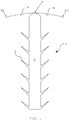
- FIG. 1 shows a drainage device 4 according to the invention for the discharge of liquids, especially water from the top of tiles.
- the dewatering device 4 comprises a joint anchoring shaft 2, on each of which six retaining elements 3 in the form of lamellae are arranged on opposite sides in the example shown.
- a joint anchoring shaft 2 At the upper end region 6 of the joint anchoring shaft 2, two drainage mandrels 1A, 1B projecting in opposite directions are arranged, which each have a free end section 8A, 8B facing away from the joint anchoring shaft 2.
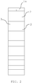
- FIG. 2 is a side view of the dewatering device according to Fig. 1 showing that the joint anchoring shaft 2 has a rectangular cross-section.
- the projecting drainage mandrels 1A, 1B taper from the joint anchoring shank 2 towards their respective free end portion 8A, 8B.
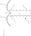
- a variant of the drainage device 4 with two arcuately protruding drainage spikes 1A, 1B and a discharge channel 7 in the upper end region 6 of the joint anchoring shaft 2 is in the FIG. 4 shown.
- the upper end portion 6 of the joint anchoring shaft 2 in this case has an incision, which forms the discharge channel 7 in this way.
- FIG. 5 is a plan view of the dewatering device 4 according to the Fig. 4 shown.
- the protruding drainage mandrels 1A, 1B taper from the joint anchoring shank 2 toward their respective free end portion 8A, 8B.
- FIG. 6 is a side view of the dewatering device 4 according to the Fig. 4 shown. Furthermore, the retaining elements 3, which are arranged on both sides of the joint anchoring shaft 2, can be seen in the form of lamellae.
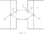
- the Fig. 7 shows the dewatering device 4 in a working state in which it was inserted into the joint between two tiles 5.
- the joint anchoring shaft 2 causes a secure fit in the joint.
- the two drainage mandrels 1A, 1B are at least partially on the chamfer 9 or the top of the tile 5.
Landscapes
- Engineering & Computer Science (AREA)
- Architecture (AREA)
- Civil Engineering (AREA)
- Structural Engineering (AREA)
- Finishing Walls (AREA)
Priority Applications (1)
| Application Number | Priority Date | Filing Date | Title |
|---|---|---|---|
| PL17186082T PL3284878T3 (pl) | 2016-08-18 | 2017-08-14 | Urządzenie odwadniające do płytek wykładzinowych |
Applications Claiming Priority (1)
| Application Number | Priority Date | Filing Date | Title |
|---|---|---|---|
| ATA50744/2016A AT518185B1 (de) | 2016-08-18 | 2016-08-18 | Entwässerungsvorrichtung für Fliesen |
Publications (2)
| Publication Number | Publication Date |
|---|---|
| EP3284878A1 true EP3284878A1 (fr) | 2018-02-21 |
| EP3284878B1 EP3284878B1 (fr) | 2020-03-11 |
Family
ID=59579974
Family Applications (1)
| Application Number | Title | Priority Date | Filing Date |
|---|---|---|---|
| EP17186082.8A Active EP3284878B1 (fr) | 2016-08-18 | 2017-08-14 | Dispositif de drainage pour dalles pour revêtement de sol |
Country Status (5)
| Country | Link |
|---|---|
| EP (1) | EP3284878B1 (fr) |
| AT (1) | AT518185B1 (fr) |
| DK (1) | DK3284878T3 (fr) |
| ES (1) | ES2795880T3 (fr) |
| PL (1) | PL3284878T3 (fr) |
Cited By (1)
| Publication number | Priority date | Publication date | Assignee | Title |
|---|---|---|---|---|
| CN113089404A (zh) * | 2021-05-26 | 2021-07-09 | 苏州吴林园林发展有限公司 | 景观工程铺设的多孔轻质透水路面砖结构 |
Families Citing this family (1)
| Publication number | Priority date | Publication date | Assignee | Title |
|---|---|---|---|---|
| AT527640B1 (de) | 2024-02-14 | 2025-03-15 | Leitner Franz | Entwässerungsvorrichtung für Platten |
Citations (4)
| Publication number | Priority date | Publication date | Assignee | Title |
|---|---|---|---|---|
| FR2328811A1 (fr) * | 1975-10-21 | 1977-05-20 | Upat Max Langensiepen Kg | Dispositif de fixation pour panneaux de construction legers |
| EP2075376A2 (fr) * | 2007-12-24 | 2009-07-01 | Alan Martin Millmore | Dispositif et système de drainage urbain durable |
| GB2459645A (en) * | 2008-04-25 | 2009-11-04 | Alan Martin Millmore | Drainage device |
| DE102012109684A1 (de) * | 2012-10-11 | 2014-04-17 | Andrè Bürmann | Einschlagdübel |
Family Cites Families (7)
| Publication number | Priority date | Publication date | Assignee | Title |
|---|---|---|---|---|
| FR2329822A1 (fr) * | 1975-10-27 | 1977-05-27 | Bouygues Sa | Dispositif de support de dalles de circulation |
| DE4415575A1 (de) * | 1994-05-03 | 1995-11-09 | Sf Koop Gmbh Beton Konzepte | Erdreichabdeckung aus Beton-Formsteinen sowie Verfahren und Vorrichtung zum Erhalten der Sickerfähigkeit einer derartigen Erdreichabdeckung |
| DE19735608A1 (de) * | 1997-08-15 | 1999-03-11 | Hermann Terborg | Verfugung für Bodenplatten jedweder Art |
| KR100974203B1 (ko) * | 2010-03-04 | 2010-08-05 | 세기하이테크건설 주식회사 | 모세관 기능을 가지는 유도배수 다공질 배수판을 이용한 신축이음부재 및 이를 이용한 시공방법 |
| KR101124608B1 (ko) * | 2011-09-05 | 2012-03-20 | 박건호 | 통수성 블록 |
| KR101510517B1 (ko) * | 2013-05-09 | 2015-04-17 | 정윤기 | 보도블록용 배수부재 |
| KR101357760B1 (ko) * | 2013-08-12 | 2014-02-05 | 한국석유공업 주식회사 | 줄눈재 조성물, 이를 이용한 주입용 줄눈재 및 성형 줄눈재와 줄눈 시공방법 |
-
2016
- 2016-08-18 AT ATA50744/2016A patent/AT518185B1/de active
-
2017
- 2017-08-14 ES ES17186082T patent/ES2795880T3/es active Active
- 2017-08-14 DK DK17186082.8T patent/DK3284878T3/da active
- 2017-08-14 EP EP17186082.8A patent/EP3284878B1/fr active Active
- 2017-08-14 PL PL17186082T patent/PL3284878T3/pl unknown
Patent Citations (4)
| Publication number | Priority date | Publication date | Assignee | Title |
|---|---|---|---|---|
| FR2328811A1 (fr) * | 1975-10-21 | 1977-05-20 | Upat Max Langensiepen Kg | Dispositif de fixation pour panneaux de construction legers |
| EP2075376A2 (fr) * | 2007-12-24 | 2009-07-01 | Alan Martin Millmore | Dispositif et système de drainage urbain durable |
| GB2459645A (en) * | 2008-04-25 | 2009-11-04 | Alan Martin Millmore | Drainage device |
| DE102012109684A1 (de) * | 2012-10-11 | 2014-04-17 | Andrè Bürmann | Einschlagdübel |
Cited By (1)
| Publication number | Priority date | Publication date | Assignee | Title |
|---|---|---|---|---|
| CN113089404A (zh) * | 2021-05-26 | 2021-07-09 | 苏州吴林园林发展有限公司 | 景观工程铺设的多孔轻质透水路面砖结构 |
Also Published As
| Publication number | Publication date |
|---|---|
| PL3284878T3 (pl) | 2020-10-19 |
| AT518185A4 (de) | 2017-08-15 |
| AT518185B1 (de) | 2017-08-15 |
| DK3284878T3 (da) | 2020-06-15 |
| EP3284878B1 (fr) | 2020-03-11 |
| ES2795880T3 (es) | 2020-11-25 |
Similar Documents
| Publication | Publication Date | Title |
|---|---|---|
| EP0077918B1 (fr) | Jointe d'étanchéité pour jonction à emmanchement de tuyaux en béton | |
| EP3271525B1 (fr) | Équipement de finition d'une portion de sol ayant un revêtement fait de plaques ou de gravier | |
| EP3284878B1 (fr) | Dispositif de drainage pour dalles pour revêtement de sol | |
| EP2902567B1 (fr) | Revêtement de sol en panneaux | |
| EP3436638B1 (fr) | Structure de transition servant au pontage d'un joint de construction | |
| DE102025000917A1 (de) | Vorrichtung zum Verspannen von Bauplatten | |
| DE29823252U1 (de) | Trennprofil für Fließböden | |
| DE102018112634B4 (de) | Fugenprofil | |
| AT527640B1 (de) | Entwässerungsvorrichtung für Platten | |
| DE19955753B4 (de) | Wasserleitprofil | |
| DE102018119205B4 (de) | Vorrichtung zum Durchführen einer Leitung durch eine Bodenplatte und Bodenplatte für ein Gebäude | |
| DE2239574C2 (de) | Aus Anschluß- und Klemmleiste mit Überhangstreifen bestehendes Wandanschlußsystem | |
| DE10200642B4 (de) | Sturmsicheres Bedachungssystem | |
| EP3375944B1 (fr) | Conduite de drainage, procédé de fabrication et procédé de montage | |
| EP2813642A2 (fr) | Profilé destiné à ériger des bandes de joints de dilatation | |
| DE10109159A1 (de) | Entwässerungsrinne | |
| DE4222729C2 (de) | Gratentlüftungselement | |
| DE29711089U1 (de) | Schutzvorrichtung für Dachrinnen zur Verhinderung eines Laubeinfalles | |
| DE202019102263U1 (de) | Kanal aus Blech oder Kunststoff mit Querstreben | |
| DE2061349C3 (de) | Auflager für die Platten eines über einer Abdichtungsschicht von Bauwerken angeordneten Plattenbelags | |
| DE29620999U1 (de) | Dichtungsprofil zum Abdichten von Fugen zwischen Betonbreitschwellen für den Gleisbau | |
| DE202022106233U1 (de) | Fassadenrinne | |
| DE202009014911U1 (de) | Schalungselement für eine Stützvorrichtung | |
| EP3617413A1 (fr) | Élément de renforcement pour goulotte de drainage | |
| EP1832684B1 (fr) | Bande profilée et revêtement de construction |
Legal Events
| Date | Code | Title | Description |
|---|---|---|---|
| PUAI | Public reference made under article 153(3) epc to a published international application that has entered the european phase |
Free format text: ORIGINAL CODE: 0009012 |
|
| STAA | Information on the status of an ep patent application or granted ep patent |
Free format text: STATUS: THE APPLICATION HAS BEEN PUBLISHED |
|
| AK | Designated contracting states |
Kind code of ref document: A1 Designated state(s): AL AT BE BG CH CY CZ DE DK EE ES FI FR GB GR HR HU IE IS IT LI LT LU LV MC MK MT NL NO PL PT RO RS SE SI SK SM TR |
|
| AX | Request for extension of the european patent |
Extension state: BA ME |
|
| STAA | Information on the status of an ep patent application or granted ep patent |
Free format text: STATUS: REQUEST FOR EXAMINATION WAS MADE |
|
| 17P | Request for examination filed |
Effective date: 20180814 |
|
| RBV | Designated contracting states (corrected) |
Designated state(s): AL AT BE BG CH CY CZ DE DK EE ES FI FR GB GR HR HU IE IS IT LI LT LU LV MC MK MT NL NO PL PT RO RS SE SI SK SM TR |
|
| STAA | Information on the status of an ep patent application or granted ep patent |
Free format text: STATUS: EXAMINATION IS IN PROGRESS |
|
| 17Q | First examination report despatched |
Effective date: 20190306 |
|
| GRAP | Despatch of communication of intention to grant a patent |
Free format text: ORIGINAL CODE: EPIDOSNIGR1 |
|
| STAA | Information on the status of an ep patent application or granted ep patent |
Free format text: STATUS: GRANT OF PATENT IS INTENDED |
|
| INTG | Intention to grant announced |
Effective date: 20190930 |
|
| GRAS | Grant fee paid |
Free format text: ORIGINAL CODE: EPIDOSNIGR3 |
|
| GRAA | (expected) grant |
Free format text: ORIGINAL CODE: 0009210 |
|
| STAA | Information on the status of an ep patent application or granted ep patent |
Free format text: STATUS: THE PATENT HAS BEEN GRANTED |
|
| AK | Designated contracting states |
Kind code of ref document: B1 Designated state(s): AL AT BE BG CH CY CZ DE DK EE ES FI FR GB GR HR HU IE IS IT LI LT LU LV MC MK MT NL NO PL PT RO RS SE SI SK SM TR |
|
| REG | Reference to a national code |
Ref country code: GB Ref legal event code: FG4D Free format text: NOT ENGLISH |
|
| REG | Reference to a national code |
Ref country code: CH Ref legal event code: EP |
|
| REG | Reference to a national code |
Ref country code: AT Ref legal event code: REF Ref document number: 1243312 Country of ref document: AT Kind code of ref document: T Effective date: 20200315 |
|
| REG | Reference to a national code |
Ref country code: IE Ref legal event code: FG4D Free format text: LANGUAGE OF EP DOCUMENT: GERMAN |
|
| REG | Reference to a national code |
Ref country code: DE Ref legal event code: R096 Ref document number: 502017004155 Country of ref document: DE |
|
| REG | Reference to a national code |
Ref country code: CH Ref legal event code: NV Representative=s name: PATENTANWAELTE SCHAAD, BALASS, MENZL AND PARTN, CH |
|
| REG | Reference to a national code |
Ref country code: FI Ref legal event code: FGE |
|
| REG | Reference to a national code |
Ref country code: DK Ref legal event code: T3 Effective date: 20200610 |
|
| REG | Reference to a national code |
Ref country code: NL Ref legal event code: FP |
|
| REG | Reference to a national code |
Ref country code: SE Ref legal event code: TRGR |
|
| PG25 | Lapsed in a contracting state [announced via postgrant information from national office to epo] |
Ref country code: RS Free format text: LAPSE BECAUSE OF FAILURE TO SUBMIT A TRANSLATION OF THE DESCRIPTION OR TO PAY THE FEE WITHIN THE PRESCRIBED TIME-LIMIT Effective date: 20200311 |
|
| REG | Reference to a national code |
Ref country code: NO Ref legal event code: T2 Effective date: 20200311 |
|
| PG25 | Lapsed in a contracting state [announced via postgrant information from national office to epo] |
Ref country code: HR Free format text: LAPSE BECAUSE OF FAILURE TO SUBMIT A TRANSLATION OF THE DESCRIPTION OR TO PAY THE FEE WITHIN THE PRESCRIBED TIME-LIMIT Effective date: 20200311 Ref country code: GR Free format text: LAPSE BECAUSE OF FAILURE TO SUBMIT A TRANSLATION OF THE DESCRIPTION OR TO PAY THE FEE WITHIN THE PRESCRIBED TIME-LIMIT Effective date: 20200612 Ref country code: BG Free format text: LAPSE BECAUSE OF FAILURE TO SUBMIT A TRANSLATION OF THE DESCRIPTION OR TO PAY THE FEE WITHIN THE PRESCRIBED TIME-LIMIT Effective date: 20200611 Ref country code: LV Free format text: LAPSE BECAUSE OF FAILURE TO SUBMIT A TRANSLATION OF THE DESCRIPTION OR TO PAY THE FEE WITHIN THE PRESCRIBED TIME-LIMIT Effective date: 20200311 |
|
| REG | Reference to a national code |
Ref country code: LT Ref legal event code: MG4D |
|
| PG25 | Lapsed in a contracting state [announced via postgrant information from national office to epo] |
Ref country code: RO Free format text: LAPSE BECAUSE OF FAILURE TO SUBMIT A TRANSLATION OF THE DESCRIPTION OR TO PAY THE FEE WITHIN THE PRESCRIBED TIME-LIMIT Effective date: 20200311 Ref country code: CZ Free format text: LAPSE BECAUSE OF FAILURE TO SUBMIT A TRANSLATION OF THE DESCRIPTION OR TO PAY THE FEE WITHIN THE PRESCRIBED TIME-LIMIT Effective date: 20200311 Ref country code: EE Free format text: LAPSE BECAUSE OF FAILURE TO SUBMIT A TRANSLATION OF THE DESCRIPTION OR TO PAY THE FEE WITHIN THE PRESCRIBED TIME-LIMIT Effective date: 20200311 Ref country code: PT Free format text: LAPSE BECAUSE OF FAILURE TO SUBMIT A TRANSLATION OF THE DESCRIPTION OR TO PAY THE FEE WITHIN THE PRESCRIBED TIME-LIMIT Effective date: 20200805 Ref country code: SK Free format text: LAPSE BECAUSE OF FAILURE TO SUBMIT A TRANSLATION OF THE DESCRIPTION OR TO PAY THE FEE WITHIN THE PRESCRIBED TIME-LIMIT Effective date: 20200311 Ref country code: IS Free format text: LAPSE BECAUSE OF FAILURE TO SUBMIT A TRANSLATION OF THE DESCRIPTION OR TO PAY THE FEE WITHIN THE PRESCRIBED TIME-LIMIT Effective date: 20200711 Ref country code: LT Free format text: LAPSE BECAUSE OF FAILURE TO SUBMIT A TRANSLATION OF THE DESCRIPTION OR TO PAY THE FEE WITHIN THE PRESCRIBED TIME-LIMIT Effective date: 20200311 Ref country code: SM Free format text: LAPSE BECAUSE OF FAILURE TO SUBMIT A TRANSLATION OF THE DESCRIPTION OR TO PAY THE FEE WITHIN THE PRESCRIBED TIME-LIMIT Effective date: 20200311 |
|
| REG | Reference to a national code |
Ref country code: ES Ref legal event code: FG2A Ref document number: 2795880 Country of ref document: ES Kind code of ref document: T3 Effective date: 20201125 |
|
| REG | Reference to a national code |
Ref country code: DE Ref legal event code: R097 Ref document number: 502017004155 Country of ref document: DE |
|
| PLBE | No opposition filed within time limit |
Free format text: ORIGINAL CODE: 0009261 |
|
| STAA | Information on the status of an ep patent application or granted ep patent |
Free format text: STATUS: NO OPPOSITION FILED WITHIN TIME LIMIT |
|
| 26N | No opposition filed |
Effective date: 20201214 |
|
| PG25 | Lapsed in a contracting state [announced via postgrant information from national office to epo] |
Ref country code: SI Free format text: LAPSE BECAUSE OF FAILURE TO SUBMIT A TRANSLATION OF THE DESCRIPTION OR TO PAY THE FEE WITHIN THE PRESCRIBED TIME-LIMIT Effective date: 20200311 |
|
| PG25 | Lapsed in a contracting state [announced via postgrant information from national office to epo] |
Ref country code: MC Free format text: LAPSE BECAUSE OF FAILURE TO SUBMIT A TRANSLATION OF THE DESCRIPTION OR TO PAY THE FEE WITHIN THE PRESCRIBED TIME-LIMIT Effective date: 20200311 |
|
| PG25 | Lapsed in a contracting state [announced via postgrant information from national office to epo] |
Ref country code: IE Free format text: LAPSE BECAUSE OF NON-PAYMENT OF DUE FEES Effective date: 20200814 |
|
| PG25 | Lapsed in a contracting state [announced via postgrant information from national office to epo] |
Ref country code: TR Free format text: LAPSE BECAUSE OF FAILURE TO SUBMIT A TRANSLATION OF THE DESCRIPTION OR TO PAY THE FEE WITHIN THE PRESCRIBED TIME-LIMIT Effective date: 20200311 Ref country code: MT Free format text: LAPSE BECAUSE OF FAILURE TO SUBMIT A TRANSLATION OF THE DESCRIPTION OR TO PAY THE FEE WITHIN THE PRESCRIBED TIME-LIMIT Effective date: 20200311 Ref country code: CY Free format text: LAPSE BECAUSE OF FAILURE TO SUBMIT A TRANSLATION OF THE DESCRIPTION OR TO PAY THE FEE WITHIN THE PRESCRIBED TIME-LIMIT Effective date: 20200311 |
|
| PG25 | Lapsed in a contracting state [announced via postgrant information from national office to epo] |
Ref country code: MK Free format text: LAPSE BECAUSE OF FAILURE TO SUBMIT A TRANSLATION OF THE DESCRIPTION OR TO PAY THE FEE WITHIN THE PRESCRIBED TIME-LIMIT Effective date: 20200311 Ref country code: AL Free format text: LAPSE BECAUSE OF FAILURE TO SUBMIT A TRANSLATION OF THE DESCRIPTION OR TO PAY THE FEE WITHIN THE PRESCRIBED TIME-LIMIT Effective date: 20200311 |
|
| P01 | Opt-out of the competence of the unified patent court (upc) registered |
Effective date: 20230427 |
|
| PGFP | Annual fee paid to national office [announced via postgrant information from national office to epo] |
Ref country code: LU Payment date: 20250825 Year of fee payment: 9 Ref country code: NL Payment date: 20250825 Year of fee payment: 9 |
|
| PGFP | Annual fee paid to national office [announced via postgrant information from national office to epo] |
Ref country code: ES Payment date: 20250901 Year of fee payment: 9 Ref country code: FI Payment date: 20250825 Year of fee payment: 9 |
|
| PGFP | Annual fee paid to national office [announced via postgrant information from national office to epo] |
Ref country code: DK Payment date: 20250728 Year of fee payment: 9 Ref country code: DE Payment date: 20250828 Year of fee payment: 9 |
|
| PGFP | Annual fee paid to national office [announced via postgrant information from national office to epo] |
Ref country code: NO Payment date: 20250819 Year of fee payment: 9 |
|
| PGFP | Annual fee paid to national office [announced via postgrant information from national office to epo] |
Ref country code: PL Payment date: 20250722 Year of fee payment: 9 Ref country code: IT Payment date: 20250725 Year of fee payment: 9 |
|
| PGFP | Annual fee paid to national office [announced via postgrant information from national office to epo] |
Ref country code: BE Payment date: 20250827 Year of fee payment: 9 Ref country code: GB Payment date: 20250828 Year of fee payment: 9 |
|
| PGFP | Annual fee paid to national office [announced via postgrant information from national office to epo] |
Ref country code: FR Payment date: 20250725 Year of fee payment: 9 Ref country code: AT Payment date: 20250822 Year of fee payment: 9 |
|
| PGFP | Annual fee paid to national office [announced via postgrant information from national office to epo] |
Ref country code: CH Payment date: 20250901 Year of fee payment: 9 Ref country code: SE Payment date: 20250825 Year of fee payment: 9 |