EP3284881A1 - Behälter zur aufbewahrung einer lösung und dosiersystem für eine wasseraufbereitung - Google Patents
Behälter zur aufbewahrung einer lösung und dosiersystem für eine wasseraufbereitung Download PDFInfo
- Publication number
- EP3284881A1 EP3284881A1 EP17186393.9A EP17186393A EP3284881A1 EP 3284881 A1 EP3284881 A1 EP 3284881A1 EP 17186393 A EP17186393 A EP 17186393A EP 3284881 A1 EP3284881 A1 EP 3284881A1
- Authority
- EP
- European Patent Office
- Prior art keywords
- container
- solution
- dosing system
- granules
- filled
- Prior art date
- Legal status (The legal status is an assumption and is not a legal conclusion. Google has not performed a legal analysis and makes no representation as to the accuracy of the status listed.)
- Granted
Links
Images




Classifications
-
- C—CHEMISTRY; METALLURGY
- C02—TREATMENT OF WATER, WASTE WATER, SEWAGE, OR SLUDGE
- C02F—TREATMENT OF WATER, WASTE WATER, SEWAGE, OR SLUDGE
- C02F1/00—Treatment of water, waste water, or sewage
- C02F1/52—Treatment of water, waste water, or sewage by flocculation or precipitation of suspended impurities
- C02F1/5281—Installations for water purification using chemical agents
-
- B—PERFORMING OPERATIONS; TRANSPORTING
- B65—CONVEYING; PACKING; STORING; HANDLING THIN OR FILAMENTARY MATERIAL
- B65D—CONTAINERS FOR STORAGE OR TRANSPORT OF ARTICLES OR MATERIALS, e.g. BAGS, BARRELS, BOTTLES, BOXES, CANS, CARTONS, CRATES, DRUMS, JARS, TANKS, HOPPERS, FORWARDING CONTAINERS; ACCESSORIES, CLOSURES, OR FITTINGS THEREFOR; PACKAGING ELEMENTS; PACKAGES
- B65D75/00—Packages comprising articles or materials partially or wholly enclosed in strips, sheets, blanks, tubes or webs of flexible sheet material, e.g. in folded wrappers
- B65D75/52—Details
- B65D75/58—Opening or contents-removing devices added or incorporated during package manufacture
- B65D75/5861—Spouts
- B65D75/5872—Non-integral spouts
-
- C—CHEMISTRY; METALLURGY
- C02—TREATMENT OF WATER, WASTE WATER, SEWAGE, OR SLUDGE
- C02F—TREATMENT OF WATER, WASTE WATER, SEWAGE, OR SLUDGE
- C02F1/00—Treatment of water, waste water, or sewage
- C02F1/68—Treatment of water, waste water, or sewage by addition of specified substances, e.g. trace elements, for ameliorating potable water
- C02F1/685—Devices for dosing the additives
-
- E—FIXED CONSTRUCTIONS
- E04—BUILDING
- E04H—BUILDINGS OR LIKE STRUCTURES FOR PARTICULAR PURPOSES; SWIMMING OR SPLASH BATHS OR POOLS; MASTS; FENCING; TENTS OR CANOPIES, IN GENERAL
- E04H4/00—Swimming or splash baths or pools
- E04H4/12—Devices or arrangements for circulating water, i.e. devices for removal of polluted water, cleaning baths or for water treatment
- E04H4/1209—Treatment of water for swimming pools
-
- E—FIXED CONSTRUCTIONS
- E04—BUILDING
- E04H—BUILDINGS OR LIKE STRUCTURES FOR PARTICULAR PURPOSES; SWIMMING OR SPLASH BATHS OR POOLS; MASTS; FENCING; TENTS OR CANOPIES, IN GENERAL
- E04H4/00—Swimming or splash baths or pools
- E04H4/12—Devices or arrangements for circulating water, i.e. devices for removal of polluted water, cleaning baths or for water treatment
- E04H4/1281—Devices for distributing chemical products in the water of swimming pools
-
- C—CHEMISTRY; METALLURGY
- C02—TREATMENT OF WATER, WASTE WATER, SEWAGE, OR SLUDGE
- C02F—TREATMENT OF WATER, WASTE WATER, SEWAGE, OR SLUDGE
- C02F1/00—Treatment of water, waste water, or sewage
- C02F1/66—Treatment of water, waste water, or sewage by neutralisation; pH adjustment
-
- C—CHEMISTRY; METALLURGY
- C02—TREATMENT OF WATER, WASTE WATER, SEWAGE, OR SLUDGE
- C02F—TREATMENT OF WATER, WASTE WATER, SEWAGE, OR SLUDGE
- C02F1/00—Treatment of water, waste water, or sewage
- C02F1/72—Treatment of water, waste water, or sewage by oxidation
- C02F1/76—Treatment of water, waste water, or sewage by oxidation with halogens or compounds of halogens
-
- C—CHEMISTRY; METALLURGY
- C02—TREATMENT OF WATER, WASTE WATER, SEWAGE, OR SLUDGE
- C02F—TREATMENT OF WATER, WASTE WATER, SEWAGE, OR SLUDGE
- C02F2103/00—Nature of the water, waste water, sewage or sludge to be treated
- C02F2103/42—Nature of the water, waste water, sewage or sludge to be treated from bathing facilities, e.g. swimming pools
-
- C—CHEMISTRY; METALLURGY
- C02—TREATMENT OF WATER, WASTE WATER, SEWAGE, OR SLUDGE
- C02F—TREATMENT OF WATER, WASTE WATER, SEWAGE, OR SLUDGE
- C02F2201/00—Apparatus for treatment of water, waste water or sewage
- C02F2201/002—Construction details of the apparatus
- C02F2201/004—Seals, connections
-
- C—CHEMISTRY; METALLURGY
- C02—TREATMENT OF WATER, WASTE WATER, SEWAGE, OR SLUDGE
- C02F—TREATMENT OF WATER, WASTE WATER, SEWAGE, OR SLUDGE
- C02F2201/00—Apparatus for treatment of water, waste water or sewage
- C02F2201/008—Mobile apparatus and plants, e.g. mounted on a vehicle
-
- C—CHEMISTRY; METALLURGY
- C02—TREATMENT OF WATER, WASTE WATER, SEWAGE, OR SLUDGE
- C02F—TREATMENT OF WATER, WASTE WATER, SEWAGE, OR SLUDGE
- C02F2209/00—Controlling or monitoring parameters in water treatment
- C02F2209/42—Liquid level
-
- C—CHEMISTRY; METALLURGY
- C02—TREATMENT OF WATER, WASTE WATER, SEWAGE, OR SLUDGE
- C02F—TREATMENT OF WATER, WASTE WATER, SEWAGE, OR SLUDGE
- C02F2303/00—Specific treatment goals
- C02F2303/04—Disinfection
Definitions
- the invention relates to a container for storing a solution of a disinfectant or a solution of a pH correcting agent or a solution of a flocculant.
- the invention also relates to a dosing system for a water treatment.
- the filling devices are part of a dosing system for a water treatment, especially for swimming pools of medium size, for water treatment, disinfection of the water and optionally pH correction and optionally or alternatively a targeted flocculation by means of a flocculant takes place, deliberately produced flakes initially unwanted impurities bind the water and then collected in a filter. Such relatively large flakes are better filterable than the unbound comparatively small impurities.
- a waterproof container of flexible material containing ion exchange material and comprising an opening formed as a neck or spout is known.
- a moisture-impermeable container in which a mixture consisting of dry components is stored.
- the invention is based on the object to provide an improved generic container and an improved generic dosage system.
- the object is achieved with respect to the container according to the invention by means of a container according to claim 1.
- the object is achieved according to the invention by means of a metering system according to claim 3.
- a container is for storing a solution of a disinfectant or a solution of a pH correcting agent or a solution of a flocculant.
- the container comprises an at least partially flexible, foldable casing with exactly one closable opening for closing, filling and emptying.
- the shell according to the invention is in an at least partially folded Delivered state filled with a disinfectant granules or a pH correction agent granules or a flocculant granules and filled for a filled state of use with the respective solution, the solution can be prepared by adding water to the respective granules in the container.
- a flexible, foldable casing should be understood to mean such a casing which is fluid-impermeable and tear-resistant, but not elastic, such as rubber.
- the shell is chemically resistant to the granules to be absorbed by it.
- the envelope is a film made of plastic.
- a filled state of use of the container is to be understood as meaning a state in which the granules are completely dissolved and the container is or is at least almost completely filled, but no pressure is built up in the container which leads or can lead to unintentional overstretching of the casing , In particular, the addition of water in a defined amount, so that the capacity of the container is not exceeded.
- the container according to the invention makes it possible to produce a solution to be used for a water treatment for disinfection or for a pH correction or flocculation only immediately before the respective use in a dosing system for a water treatment. This is particularly advantageous, since a usability of the respective solution over the prior art is extended.
- the formation of unwanted chlorates in disinfectants begins when using a container according to the invention only later than in the prior art, so that reaching an allowable limit occurs later than in the prior art.
- a metering system for a water treatment with improved efficiency to operate.
- the container is filled in its delivery state with granules and not already with the finished solution and folded due to its Falt sadness, the container is compared to known containers, both relatively light and relatively small. As a result, the delivery, in particular a shipment of a small number of containers to individual customers, with improved efficiency allows.
- the container In the filled state of use, the container preferably has a substantially cuboidal shape.
- the container can be used well and defined in a receiving unit of a filling device.
- the shape of the container in the filled state of use corresponds to the shape of the receiving unit.
- the container in its delivery state also has a substantially cuboidal shape, wherein the base of the container in its delivery state is approximately equal to the base of the container in its filled state of use and wherein the height of the container in its delivery state significantly smaller than the height of Container is in its filled state of use.
- the container is airtight sealable in the delivery condition. In the hermetically sealed container, no or only little oxygen is available on delivery.
- An embodiment of the container according to the invention provides that in the delivery state as a disinfectant granules, a chlorine granules or KPMS (potassium peroxomonosulfate), as pH correction agent granules, a hydrogen sulfate or a hydrogen carbonate or flocculant granules aluminum hydroxychloride is filled.
- a disinfectant granules a chlorine granules or KPMS (potassium peroxomonosulfate)
- pH correction agent granules a hydrogen sulfate or a hydrogen carbonate or flocculant granules aluminum hydroxychloride is filled.
- chlorine granules it is particularly preferable to use calcium hypochlorite, dichloroisocyanuric acid or trichloroisocyanuric acid.
- hydrogen sulfate becomes special preferably sodium hydrogen sulfate used.
- bicarbonate sodium bicarbonate is particularly preferably used.
- the granules mentioned are particularly well suited for the preparation of a solution of a disinfectant or a solution of a pH correcting agent or a solution of a flocculant and particularly stable and durable granules, especially if the container is hermetically sealed in the delivery condition and in the airtight container in the delivery state no or only little oxygen is present. In particular, the unwanted formation of chlorate is significantly reduced compared to a conventional container.
- the container according to the invention provides a non-flexible connection element forming the opening.
- the container is particularly easy to close and easy to fix.
- the connection element has a collar and a thread.
- the connection element is formed for example from plastic.
- a further embodiment of the container according to the invention provides that the volume of the container in the delivery state is less than 10 liters and that the volume of the container in the filled state of use is between 25 liters and 35 liters, in particular 29 to 31 liters. This is advantageous because shipping in the delivery state is particularly easy and loading a corresponding filling of a dosing system for a water treatment is also very easy.
- a filling device of a dispensing device and a holding device for a number of containers comprising metering system is used for a water treatment.
- the metering system has a number of containers according to the invention.
- two containers according to the invention are provided, wherein a first container with a granulate for producing a solution of a disinfectant or such a solution and a second container with a granulate for producing a Solution of a pH correction agent or such a solution is filled or filled.
- a third container is provided with a granulate for producing a solution of a flocculant or such a solution.
- One embodiment of the metering system provides a receiving unit for receiving a number of containers, wherein the receiving unit has at least one segment and wherein a shape of the segment corresponds to the shape of a number of filled containers.
- each segment has a liquid-permeable receiving bottom, a liquid-impermeable collecting basin arranged underneath, and a liquid-impermeable wall.
- the insertion of a prefabricated container in its delivery state in a corresponding segment is thus particularly simple and secure, whereby operator error can be reduced or largely avoided.
- the volume of the container increases by unfolding its shell, particularly preferably only increases the height of the container, and that until it is completely filled with the forming solution.
- as much granulate is disposed in the container as can be completely dissolved by adding water without liquid overflows unintentionally.
- the shape of a segment is chosen so that this shape corresponds to the shape of a filled container. Then the insertion of a container in its delivery state is particularly simple.
- the shape of the segment is selected so that this shape corresponds to the shape of several, in particular two, filled containers.
- a further embodiment of the metering system according to the invention provides that the receiving unit has a detection unit for detecting a presence and / or a filling level of a container.
- the detection unit on an inner side of a segment, which is for receiving exactly one container is formed, arranged.
- the effect that increases the volume of a container during filling and decreases when removing solution, is exploited in a particularly advantageous manner for the automatic detection of a level. It is particularly advantageous that an automatic detection is possible.
- it is advantageous that a timely detection of impending complete emptying is possible, so that a timely reordering or refilling of a new container according to the invention in delivery state is possible.
- the fact that the detection unit is arranged outside the container, a change of a container is particularly easy, and in addition the detection security is particularly large.
- a lower sensor for example a pressure sensor
- a pressure sensor is arranged on an upper side of the receiving floor on which a container can be placed.
- this lower sensor can be detected whether a container is arranged in the segment.
- it is detectable with this lower sensor when exceeding or falling below a limit value of a pressure, whether a defined level is reached in the container when filled with water and the filling can be stopped automatically or if another defined level in the container when removing a solution is reached .
- Characterized in that the shell of the container according to the invention is flexible, a level is surprisingly accurate to determine when a pressure acting on the lower sensor is detected.
- an upper sensor for example a pressure sensor, is arranged on an inner side of the wall of the segment into which a container is adjustable.
- this upper sensor is also detected when exceeding or falling below a limit value of a pressure, whether a defined level is reached in the container when filled with water and the filling can be stopped automatically or if another defined level in the container is fallen below when removing a solution ,
- information about a level can be verified, which by a pressure detection was determined by the lower sensor.
- the envelope of the container according to the invention is flexible, it is possible to determine a fill level surprisingly accurately or to verify information determined for this purpose when a pressure acting on the upper sensor is detected. It is possible to generate an automatic reordering of a new container in the delivery state upon detection of an existing or imminent vacancy of the container.
- the detection unit for each container comprises the lower sensor and the upper sensor. Thereby, a presence and or a level for each container is separately and safely detected.
- the dosing system according to the invention provides a fixing unit for fixing a connection element arranged in the region of the opening of the container and thus for fixing the container.
- the connection element is, unlike the shell, not flexible, so that the container is precisely positioned and easy to fix.
- the fixing unit according to the invention is angular, wherein the connecting element can be inserted horizontally into a slot of a horizontal leg of the connecting element.
- a further embodiment of the metering system according to the invention provides exactly one lance for filling and emptying each of a container.
- a first and a second line which serve for filling or for emptying, each guided to the foot of the lance.
- the lance also includes a line for degassing. This undesired gases can be selectively removed to avoid bursting of the container and fed to an optional activated carbon filter.
- the line for degassing ends in an upper region of the lance, for example, directly under a screw attachment thereof, with which the lance can be connected to a connection element of the container, in particular screwed.
- a further development of this embodiment provides that a spray head is arranged at the lower end of the lance.
- a development of this embodiment with lance provides that a monitoring device is provided for monitoring a safe and proper seat of the lance in the container or for monitoring the assignment of the correct lance to the respective container.
- the monitoring device preferably takes place according to an RFID principle.
- a specific transponder is mounted on or in the container, which stores information about the filled granules and can pass on.
- a corresponding reading device can be attached to the lance or to a connection part. This can be ensured in a simple manner that only released by the respective manufacturer container in their delivery condition can be used.
- a further embodiment of the metering system according to the invention provides that the lance can be fixed by means of the fixing unit.
- an assembly of the lance is particularly easy and safe especially when equipping the metering with a new container.
- a further embodiment of the metering system provides that the slot of the horizontal leg of the fixing unit has a width which is slightly smaller than the width of a collar of the connecting element.
- the connection element is simply inserted into the slot in the horizontal direction and the Collar can be placed on the horizontal angle, so that the container can be easily inserted into the dosing and fixed and easily removed from this.
- the connecting element is thus inserted into the slot and fixed there at least in the vertical direction.
- the connection element is additionally fixable in the horizontal direction by clamping, for which purpose the width of the slot in the horizontal leg with the width, in particular the outer diameter of the connection element corresponds directly below the collar, that is about the same size. It is alternatively also possible that the width of the slot in the horizontal leg is slightly larger than the width, in particular the outer diameter, of the connecting element immediately below the collar.
- FIG. 1 shows a schematic representation of a first embodiment of a container 1 according to the invention in a state of use.
- the container 1 serves to store a solution L of a disinfectant or a pH correction agent or a flocculant.
- the container 1 has a flexible, foldable cover 1.1 and exactly one closable opening 1.2, wherein the opening 1.2 serves for closing, filling and emptying.
- the shell 1.1 is shown in a deployed state, in which the container 1 is already filled with one of the aforementioned solutions. In a delivery state, not shown here, at least partially folded, the container 1 is filled with a granulate 2, already dissolved and therefore not shown, for disinfection, pH correction or flocculation.
- Solution L was prepared by adding water to granule 2.
- the shell 1.1 is formed from two halves, which are connected to each other in a fluid-tight manner by means of a weld 1.1.1.
- the opening 1.2 is formed by a non-flexible connection element 1.3, which consists of plastic.
- the connection element 1.3 is arranged in a recess 1.4 of the shell 1.1.
- parameters of a container 1 may differ by +/- 5% from the parameters mentioned.
- the container 1 is prefabricated, that is, its dimensions are chosen so that it can be easily inserted into a filling device, not shown here, with corresponding dimensions.
- FIG. 2 shows an associated enlarged detail of detail of the sleeve 1.1 fluid-tightly connected connection element 1.3, which has an outer thread 1.5 and a circumferential collar 1.6.
- a clamping ring may be provided.
- connection element 1.3 may, for example, deviate by +/- 5% or by +/- 1% from the mentioned parameters.
- FIG. 3 shows a schematic representation of the container 1 in a delivery state in which a granulate 2 is filled.
- the container 1 is hardly any air except the granules 2, since the container 1 is optionally evacuated.
- the opening 1.2 formed by the connection element 1.3 is sealed airtight by means of a closure cap 1.7.
- the largely folded shell 1.1 is glued to the shape of the container 1 in its delivery state by means of a fixing belt 1.8, which is removed before using the container 1.
- FIG. 4 shows an arrangement of an embodiment of two inventive container 1 in a first embodiment of a dosing system 3 for a water treatment.
- the dosing system for water treatment comprises, in addition to the filling device, a known measuring and control unit M, a removal device for removing a solution L and a holding device for receiving and fixing the two containers 1.
- a container 1 serves to store a solution of a disinfectant
- the second container 1 serves to store a solution of a pH correction agent.
- the dosing system 3 is used for water treatment, especially for swimming pools of medium size, with the water treatment disinfecting the water and a pH correction done.
- the first filled with granules 2 container 1 were filled with water, wherein in a container 1, a solution L for disinfecting the water and in the second container 1, a solution L for a pH correction of the water was prepared.
- the dosing system 3 By means of the dosing system 3, a dose of the solution L for disinfecting and / or a dose of the solution L for a pH correction of the water is added to the water to be treated, depending on the determined need.
- the dosing system 3 has a removal device.
- the containers 1 are arranged in a holding device which is part of the dosing system 3.
- the holding device comprises a receiving unit 4, which for each container 1 has a fluid-permeable receiving base 4.1 for setting up the container 1, arranged below the receiving trays 4.1 catch basin 4.2, walls 4.3 for lateral delimitation of the container 1 and arranged between the containers partition 4.4.
- the catch basin 4.2 is used to catch an unintentionally leaking from a container 1 solution.
- the receiving unit 4 thus has two segments whose shape corresponds in each case to the shape of a filled container 1.
- a lower sensor 5 On the upper side of each receiving base 4.1, a lower sensor 5 is arranged, in each case an upper region of the wall 4.3, an upper sensor 6 is arranged.
- the sensors 5, 6 serve to detect a presence and / or a filling level of a container 1. Both sensors 5, 6 are therefore arranged on an inner side of a segment. The effect that increases the volume of a container 1 during filling and reduced when removing solution L, is thereby exploited for automatic detection of the level by means of the upper sensor 6. A timely detection of impending complete emptying is possible, so that a timely replenishment with a new container 1 in the delivery state is possible.
- a leakage sensor 7 is arranged, by means of which an unintentional leakage of a container 1 can be detected, wherein optionally a warning signal can be output and optionally an operation of the dosing system 3 is automatically interrupted.
- the filling device comprises a fixing unit 8, which is designed as a removable metal angle.
- a container 1 can be fixed to the rear wall.
- a horizontal leg has a slot in which the connection element 1.3 can be inserted.
- a lance 9 is arranged at the foot of a spray head is 9.1.
- the lance 9 has on its upper side a screwing, with which the lance 9 by screwing with the thread 1.5 of the connecting element 1.3 to the fixing unit 8 can be fastened and fixed.
- the lance 9 comprises a guided to the spray head 9.1 line for filling with water, a guided to about the bottom of the container 1 line to remove the finished solution L and just below the connection element 1.3 ending line for discharging unwanted gases.
- the spray head 9.1 is used for the targeted introduction of water at high speed and thus an improved and defined dissolution of the granules. 2
- a first filling line 10a for the first container 1 and a second filling line 10b for the second container 1 are arranged and connected to the lance 9, respectively.
- a first filling line 10a for the first container 1 and a second filling line 10b for the second container 1 are arranged and connected to the lance 9, respectively.
- the filling lines 10a, 10b L water is introduced into the respective container 1 after the latter has been used in the delivery state to form the respective solution.
- a first extraction line 11a for the first container 1 and a second extraction line 11b for the second container 1 are arranged and connected to the lance 9, respectively.
- the respective solution L is removed from the respective container 1 in a predetermined amount.
- a first metering pump 12a and a second metering pump 12b are provided, which are preferably comprised by the measuring and control unit M.
- first control unit 13a By means of a first control unit 13a, the filling of the container 1 shown on the right is controlled. This first control unit 13a also includes an input field for a manually triggered filling process for the container 1 shown on the right.
- second control unit 13b By means of a second control unit 13b, the filling of the container 1 shown on the left is controlled. This second control unit 13b also includes an input field for a manually triggered filling process for the container 1 shown on the left.
- the measuring and control unit M which is designed as a separate and replaceable component includes, in addition to the first metering pump 12a and the second metering 12b measuring cells / electrodes 14 for analyzing the water to be treated and thus to determine the need for disinfectant and pH correction means and a display 15 for displaying various values concerning the processing.
- the display or a separate input unit can be used to set various parameters for water treatment.
- a degassing line 16 is arranged, by means of which unintentionally gases formed in the container 1 can be discharged in order to prevent the container 1 from swelling or bursting.
- the discharged from the degassing 16 gas is passed into an activated carbon filter 17, in which it is largely purified.
- the dosing system 3 is designed as a system which can be set up on a floor, which optionally can also be mounted on a wall, not shown.
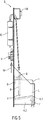
- FIG. 5 shows a schematic side view of an embodiment of a dosing system 3 for a water treatment with the first embodiment of inventive container 1.
- the filled with a solution L container 1 is placed on the receiving base 4.1.
- the upper sensor 6 is arranged on a rear wall of the metering system 3.
- the leakage sensor 7 is shown in the catch basin 4.2.
- the fixing unit 8 designed as a detachable metal angle is likewise arranged on this rear wall.
- the fixing unit 8 By means of the fixing unit 8 are both the Container 1 and the lance 9 inserted therein, which has a spray head 9.1 at the foot fixed.
- the measuring and control unit M is attached to the front of the rear wall.
- a valve V At the back of the rear wall are a valve V and a water softening cartridge E, which serves to improve a water to be fed by means of a water inlet W.
- the valve V With the valve V, the water inlet W can be opened or closed.
- the water softening cartridge E optionally has a display with which a decreasing effectiveness visually, in particular by a color change, made visible.
- FIG. 6 shows a partial bottom view of a filling device for a metering system 3, which is designed to accommodate exactly one container 1, wherein the catch basin 4.2 is not shown here.
- the dosing system 3 is used to add a flocculant.
- the arranged on the bottom plate 4.1 lower sensor 5 is connected to a cable 4.1.1 on the control system of the filling.
- an activated carbon filter 17 is shown at the front of the rear wall next to the measuring and control unit M.
- the measuring and control unit M comprises a metering pump, with which an addition of the flocculant is time-controlled or quantity-controlled.
- FIG. 7 shows an embodiment of the fixing unit 8, which is covered by the filling device.
- the fixing unit 8 is formed as a removable metal angle.
- a container 1, not shown here can be fixed to the rear wall.
- a horizontal leg has a slot into which the connection element 1.3, not shown here, can be inserted.
- the outer diameter of the collar 1.6, not shown here, which in FIG. 2 is shown is slightly larger than the width of the slot in the horizontal leg, so that the connection element 1.3 is inserted into the slot and fixed there at least in the vertical direction.
- the connection element 1.3 is additionally fixable in the horizontal direction for clamping, for which purpose the width of the slot in the horizontal leg with the width, in particular the outer diameter, of the connection element 1.3 immediately below the collar 1.6 corresponds.
- the metal angle can be removed from the rear wall, for which purpose preferably a connection between metal angle and rear wall can be released without tools.
- a filled container 1 can be removed together with the fixing unit 8 again from the receiving unit 4, after the metal angle has been released from the rear wall.
Landscapes
- Engineering & Computer Science (AREA)
- Chemical & Material Sciences (AREA)
- Water Supply & Treatment (AREA)
- Architecture (AREA)
- Life Sciences & Earth Sciences (AREA)
- Organic Chemistry (AREA)
- Structural Engineering (AREA)
- Environmental & Geological Engineering (AREA)
- Civil Engineering (AREA)
- Hydrology & Water Resources (AREA)
- Medicinal Chemistry (AREA)
- Health & Medical Sciences (AREA)
- Chemical Kinetics & Catalysis (AREA)
- General Chemical & Material Sciences (AREA)
- Mechanical Engineering (AREA)
- Containers And Packaging Bodies Having A Special Means To Remove Contents (AREA)
- Treatment Of Water By Oxidation Or Reduction (AREA)
- Water Treatment By Sorption (AREA)
Abstract
Description
- Die Erfindung betrifft einen Behälter zur Aufbewahrung einer Lösung eines Desinfektionsmittels oder einer Lösung eines pH-Korrekturmittels oder einer Lösung eines Flockungsmittels. Die Erfindung betrifft außerdem ein Dosiersystem für eine Wasseraufbereitung.
- Im Stand der Technik sind gattungsgemäße Behälter bekannt, die aus Kunststoff gebildet sind und einen nichtflexiblen Kanister bilden. Derartige bekannte Behälter werden in bekannten gattungsgemäßen Dosierungssystemen verwendet.
- Die Befüllvorrichtungen sind Bestandteil eines Dosierungssystems für eine Wasseraufbereitung, insbesondere für Schwimmbecken mittlerer Baugröße, wobei zur Wasseraufbereitung eine Desinfektion des Wassers sowie optional eine pH-Wert-Korrektur und optional oder alternativ eine gezielte Flockenbildung mittels eines Flockungsmittels erfolgt, wobei gezielt hergestellte Flocken zunächst ungewollte Verunreinigungen des Wassers binden und anschließend in einem Filter aufgefangen werden. Derartige vergleichsweise große Flocken sind besser filterbar als die ungebundenen vergleichsweise kleinen Verunreinigungen.
- Aus der
US 2016/0017622 A1 ist ein flexibler Behälter bekannt, der mit antibakteriellen Komponenten gefüllt ist. - Aus der
DE 1 517 447 sind ein Plastikfaltbeutel und ein Verfahren zur Aufbereitung von Flüssigkeit bekannt. - Aus der
US 2015/0265867 A1 ist ein zylindrischer Behälter bekannt, der mit Tonerde-Granulat gefüllt ist. - Aus der
DE 37 08 025 A1 ist ein wasserdichter Behälter aus flexiblem Material bekannt, der Ionenaustauschermaterial enthält und eine als Hals oder Tülle ausgebildete Öffnung umfasst. - Aus der
US 2009/0266841 A1 ist ein flexibler Behälter bekannt. - Aus der
US 2006/0078584 A1 ist ein feuchtigkeitsundurchlässiger Behälter bekannt, in welchem eine aus trockenen Komponenten bestehende Mischung gelagert wird. - Aus der
US 2010/0006513 A1 ist ein Gerät zur Wasserbehandlung bekannt, das Sensoren umfasst. - Aus der
DE 100 61 012 A1 sind ein Verfahren und eine Vorrichtung zur Flüssigkeitsfiltration bekannt, wobei die Vorrichtung Impflanzen mit Auslasstöpfen umfasst. - Der Erfindung liegt die Aufgabe zu Grunde, einen verbesserten gattungsgemäßen Behälter und ein verbessertes gattungsgemäßes Dosierungssystem anzugeben.
- Die Aufgabe wird hinsichtlich des Behälters erfindungsgemäß mittels eines Behälters gemäß Anspruch 1 gelöst. Hinsichtlich des Dosierungssystems wird die Aufgabe erfindungsgemäß mittels eines Dosierungssystems gemäß Anspruch 3 gelöst.
- Vorteilhafte Ausgestaltungen der Erfindung sind Gegenstand der Unteransprüche.
- Ein Behälter dient zur Aufbewahrung einer Lösung eines Desinfektionsmittels oder einer Lösung eines pH-Korrekturmittels oder einer Lösung eines Flockungsmittels. Der Behälter umfasst eine zumindest teilweise flexible, faltbare Hülle mit genau einer verschließbaren Öffnung zum Verschließen, Befüllen und Entleeren. Dabei ist die Hülle erfindungsgemäß in einem zumindest teilweise gefalteten Auslieferungszustand mit einem Desinfektions-Granulat oder einem pH-Korrekturmittel-Granulat oder einem Flockungsmittel-Granulat gefüllt und für einen gefüllten Gebrauchszustand mit der jeweiligen Lösung füllbar, wobei die Lösung durch Zugabe von Wasser zum jeweiligen Granulat im Behälter herstellbar ist.
- Unter einer flexiblen, faltbaren Hülle soll dabei eine solche Hülle verstanden werden, die fluidundurchlässig und reißfest, aber nicht, wie beispielsweise Gummi, dehnbar ist. Die Hülle ist gegenüber den von ihr aufzunehmenden Granulaten chemisch widerstandsfähig. Besonders bevorzugt ist die Hülle eine aus Kunststoff hergestellte Folie.
- Durch Zugabe von Wasser zum jeweiligen Granulat ist im Behälter die Lösung herstellbar. Unter einem gefüllten Gebrauchszustand des Behälters ist ein solcher Zustand zu verstehen, in dem das Granulat vollständig aufgelöst ist und der Behälter zumindest nahezu vollständig gefüllt ist oder wird, aber kein Druck im Behälter aufgebaut wird, der zu einer ungewollten Überdehnung der Hülle führt oder führen kann. Insbesondere erfolgt die Zugabe von Wasser in einer definierten Menge, so dass das Aufnahmevermögen des Behälters nicht überschritten wird.
- Der erfindungsgemäße Behälter ermöglicht es, eine für eine Wasseraufbereitung zu verwendende Lösung für eine Desinfektion oder für eine pH-Wert-Korrektur oder für eine Flockung erst unmittelbar vor der jeweiligen Verwendung in einem Dosiersystem für eine Wasseraufbereitung herzustellen. Dies ist besonders vorteilhaft, da eine Verwendbarkeit der jeweiligen Lösung gegenüber dem Stand der Technik verlängert ist. Insbesondere die Bildung von ungewollten Chloraten in Desinfektionsmitteln beginnt bei Verwendung eines erfindungsgemäßen Behälters erst später als im Stand der Technik, so dass ein Erreichen eines zulässigen Grenzwertes erst später als im Stand der Technik erfolgt. Dadurch ist ein Dosiersystem für eine Wasseraufbereitung mit verbesserter Wirtschaftlichkeit zu betreiben.
- Dadurch, dass der Behälter in seinem Auslieferungszustand mit Granulat und nicht bereits mit der fertigen Lösung gefüllt und aufgrund seiner Faltbarkeit gefaltet ist, ist der Behälter gegenüber bekannten Behältern sowohl vergleichsweise leicht als auch vergleichsweise klein. Dadurch ist auch die Auslieferung, insbesondere ein Versand einer kleinen Anzahl von Behältern an Einzelabnehmer, mit verbesserter Wirtschaftlichkeit ermöglicht.
- Der Behälter weist im gefüllten Gebrauchszustand bevorzugt eine im Wesentlichen quaderförmige Gestalt auf. Dadurch ist der Behälter gut und definiert in eine Aufnahmeeinheit einer Befüllvorrichtung einsetzbar. Bevorzugt korrespondiert die Form des Behälters im gefüllten Gebrauchszustand mit der Form der Aufnahmeeinheit.
- Besonders bevorzugt weist der Behälter in seinem Auslieferungszustand ebenfalls eine im Wesentlichen quaderförmige Gestalt auf, wobei die Grundfläche des Behälters in seinem Auslieferungszustand etwa gleich der Grundfläche des Behälters in seinem gefüllten Gebrauchszustand ist und wobei die Höhe des Behälters in seinem Auslieferungszustand deutlich kleiner als die Höhe des Behälters in seinem gefüllten Gebrauchszustand ist.
- Der Behälter ist im Auslieferungszustand luftdicht verschließbar. Im luftdicht verschlossenen Behälter ist im Auslieferungszustand kein oder nur wenig Sauerstoff vorhanden.
- Eine Ausgestaltung des erfindungsgemäßen Behälters sieht vor, dass im Auslieferungszustand als Desinfektions-Granulat ein Chlor-Granulat oder KPMS (Kaliumperoxomonosulfat), als pH-Korrekturmittel-Granulat ein Hydrogensulfat oder ein Hydrogenkarbonat oder als Flockungsmittel-Granulat Aluminiumhydroxychlorid eingefüllt ist.
- Als Chlor-Granulat wird besonders bevorzugt Kalziumhypochlorit, Dichlorisozyanursäure oder Trichlorisozyanursäure verwendet. Als Hydrogensulfat wird besonders bevorzugt Natriumhydrogensulfat verwendet. Als Hydrogenkarbonat wird besonders bevorzugt Natriumhydrogenkarbonat verwendet. Die genannten Granulate sind zur Herstellung einer Lösung eines Desinfektionsmittels beziehungsweise einer Lösung eines pH-Korrekturmittels beziehungsweise einer Lösung eines Flockungsmittels besonders gut geeignet und als Granulat besonders stabil und haltbar, insbesondere wenn der Behälter im Auslieferungszustand luftdicht verschlossen ist und im luftdicht verschlossenen Behälter im Auslieferungszustand kein oder nur wenig Sauerstoff vorhanden ist. Insbesondere die ungewollte Bildung von Chlorat ist dadurch gegenüber einem herkömmlichen Behälter deutlich reduzierbar.
- Der erfindungsgemäße Behälter sieht ein die Öffnung bildendes, nichtflexibles Anschlusselement vor. Mit diesem Anschlusselement ist der Behälter besonders einfach zu verschließen und einfach fixierbar. Erfindungsgemäß weist das Anschlusselement einen Kragen und ein Gewinde auf. Das Anschlusselement ist beispielsweise aus Kunststoff gebildet.
- Eine weitere Ausgestaltung des erfindungsgemäßen Behälters sieht vor, dass das Volumen des Behälters im Auslieferungszustand kleiner als 10 Liter ist und dass das Volumen des Behälters im gefüllten Gebrauchszustand zwischen 25 Liter und 35 Liter, insbesondere 29 bis 31 Liter beträgt. Dies ist vorteilhaft, da ein Versand im Auslieferungszustand besonders einfach möglich ist und ein Bestücken einer korrespondierenden Befüllvorrichtung eines Dosiersystems für eine Wasseraufbereitung ebenfalls besonders einfach ist.
- Eine Befüllvorrichtung eines eine Entnahmevorrichtung und eine Haltevorrichtung für eine Anzahl von Behältnissen umfassenden Dosiersystems dient für eine Wasseraufbereitung. Erfindungsgemäß weist das Dosiersystem eine Anzahl von erfindungsgemäßen Behältern auf. Besonders bevorzugt sind zwei erfindungsgemäße Behälter vorgesehen, wobei ein erster Behälter mit einem Granulat zur Herstellung einer Lösung eines Desinfektionsmittels beziehungsweise einer derartigen Lösung und ein zweiter Behälter mit einem Granulat zur Herstellung einer Lösung eines pH-Korrekturmittels beziehungsweise einer derartigen Lösung bestückt oder befüllt ist. Optional ist ein dritter Behälter mit einem Granulat zur Herstellung einer Lösung eines Flockungsmittels beziehungsweise einer derartigen Lösung vorgesehen. Das erfindungsgemäße Dosiersystem ist mit den für den erfindungsgemäßen Behälter genannten Vorteilen zu komplettieren.
- Eine Ausgestaltung des erfindungsgemäßen Dosiersystems sieht eine Aufnahmeeinheit zur Aufnahme einer Anzahl von Behältern vor, wobei die Aufnahmeeinheit wenigstens ein Segment aufweist und wobei eine Form des Segmentes mit der Form einer Anzahl gefüllter Behälter korrespondiert. Dabei weist jedes Segment einen flüssigkeitsdurchlässigen Aufnahmeboden, ein darunter angeordnetes flüssigkeitsundurchlässiges Auffangbecken sowie eine flüssigkeitsundurchlässige Wandung auf. Das Einsetzen eines vorkonfektionierten Behälters in dessen Auslieferungszustand in ein korrespondierendes Segment ist damit besonders einfach und sicher, wodurch Bedienfehler reduzierbar oder weitestgehend vermeidbar sind. Beim anschließenden Befüllen des Behälters mit Wasser zur Bildung der Lösung vergrößert sich das Volumen des Behälters durch Entfaltung seiner Hülle, besonders bevorzugt vergrößert sich lediglich die Höhe des Behälters, und zwar so lange, bis dieser vollständig mit der sich bildenden Lösung gefüllt ist. Bevorzugt ist im Behälter so viel Granulat angeordnet, wie sich durch Wasserzugabe vollständig lösen kann, ohne dass Flüssigkeit ungewollt überläuft.
- Besonders bevorzugt ist die Form eines Segmentes so gewählt, dass diese Form mit der Form eines gefüllten Behälters korrespondiert. Dann ist das Einsetzen eines Behälters in dessen Auslieferungszustand besonders einfach. Alternativ ist die Form Segmentes so gewählt, dass diese Form mit der Form mehrerer, insbesondere zweier, gefüllter Behälter korrespondiert.
- Eine weitere Ausgestaltung des erfindungsgemäßen Dosiersystems sieht vor, dass die Aufnahmeeinheit eine Detektionseinheit zur Detektion eines Vorhandenseins und/oder eines Füllstandes eines Behälters aufweist. Bevorzugt ist die Detektionseinheit an einer Innenseite eines Segmentes, das zur Aufnahme genau eines Behälters ausgebildet ist, angeordnet. Der Effekt, dass sich das Volumen eines Behälters beim Befüllen vergrößert und beim Entnehmen von Lösung verkleinert, wird dabei in besonders vorteilhafter Weise zur automatischen Detektion eines Füllstandes ausgenutzt. Besonders vorteilhaft ist dabei, dass eine automatische Detektion ermöglicht ist. Zudem ist vorteilhaft, dass eine rechtzeitige Detektion einer drohenden vollständigen Entleerung möglich ist, dass also eine rechtzeitige Nachorderung oder Nachbestückung eines neuen erfindungsgemäßen Behälters in Auslieferungszustand möglich ist. Dadurch, dass die Detektionseinheit außerhalb des Behälters angeordnet ist, ist ein Wechsel eines Behälters besonders einfach möglich, außerdem ist dadurch die Detektionssicherheit besonders groß.
- Bevorzugt ist ein unterer Sensor, beispielsweise ein Drucksensor, an einer Oberseite des Aufnahmebodens, auf den ein Behälter aufstellbar ist, angeordnet. Mit diesem unteren Sensor ist detektierbar, ob ein Behälter im Segment angeordnet ist. Zudem ist mit diesem unteren Sensor bei Über- oder Unterschreitung eines Grenzwertes eines Druckes detektierbar, ob ein definierter Füllstand im Behälter beim Befüllen mit Wasser erreicht ist und das Befüllen automatisch gestoppt werden kann beziehungsweise ob ein anderer definierter Füllstand im Behälter bei Entnahme einer Lösung unterschritten ist. Dadurch, dass die Hülle des erfindungsgemäßen Behälters flexibel ist, ist ein Füllstand überraschend genau zu bestimmen, wenn ein auf den unteren Sensor wirkender Druck erfasst wird.
- Besonders bevorzugt ist ein oberer Sensor, beispielsweise ein Drucksensor, an einer Innenseite des der Wandung des Segmentes, in welches ein Behälter einstellbar ist, angeordnet.
- Mit diesem oberen Sensor ist ebenfalls bei Über- oder Unterschreitung eines Grenzwertes eines Druckes detektierbar, ob ein definierter Füllstand im Behälter beim Befüllen mit Wasser erreicht ist und das Befüllen automatisch gestoppt werden kann beziehungsweise ob ein anderer definierter Füllstand im Behälter bei Entnahme einer Lösung unterschritten ist. Zusätzlich ist mittels des oberen Sensors eine Information zu einem Füllstand verifizierbar, die durch eine Druckerfassung durch den unteren Sensor ermittelt wurde. Dadurch, dass die Hülle des erfindungsgemäßen Behälters flexibel ist, ist ein Füllstand überraschend genau zu bestimmen oder eine dazu ermittelte Information zu verifizieren, wenn ein auf den oberen Sensor wirkender Druck erfasst wird. Es ist möglich, bei Detektion eines vorliegenden oder drohenden Leerstandes des Behälters ein automatisches Nachbestellen eines neuen Behälters in Auslieferungszustand zu generieren.
- Bevorzugt umfasst die Detektionseinheit für jeden Behälter jeweils den unteren Sensor sowie den oberen Sensor. Dadurch ist ein Vorhandensein und oder ein Füllstand für jeden Behälter separat und sicher erfassbar.
- Das erfindungsgemäße Dosiersystem sieht eine Fixiereinheit zur Fixierung eines im Bereich der Öffnung des Behälters angeordneten Anschlusselementes und damit zur Fixierung des Behälters vor. Das Anschlusselement ist, anders als die Hülle, nicht flexibel, so dass der Behälter genau positionierbar und leicht fixierbar ist. Die Fixiereinheit ist erfindungsgemäß winkelförmig, wobei das Anschlusselement horizontal in einen Schlitz eines horizontalen Schenkels des Anschlusselementes einsteckbar ist.
- Eine weitere Ausgestaltung der erfindungsgemäßen Dosiersystems sieht genau eine Lanze zum Befüllen und Entleeren jeweils eines Behälters vor. Dazu sind in der Lanze eine erste und eine zweite Leitung, die zum Befüllen beziehungsweise zum Entleeren dienen, jeweils bis zum Fuß der Lanze geführt. Dadurch, dass eine Lanze sowohl zum Befüllen als auch zum Entleeren des Behälters verwendet wird, muss selbiger mit lediglich einer Öffnung ausgestattet sein. Besonders vorteilhaft ist, dass die Lanze auch eine Leitung zum Entgasen umfasst. Damit können ungewollt entstehende Gase zur Meidung eines Berstens des Behälters gezielt abgeführt werden und einem optionalen Aktivkohlefilter zugeführt werden. Besonders bevorzugt endet die Leitung zum Entgasen in einem oberen Bereich der Lanze, beispielsweise unmittelbar unter einem Schraubaufsatz derselben, mit dem die Lanze mit einem Anschlusselement des Behälters verbindbar, insbesondere verschraubbar ist.
- Eine Weiterbildung dieser Ausgestaltung sieht vor, dass am unteren Ende der Lanze ein Sprühkopf angeordnet ist. Dadurch ist beim Befüllen des Behälters ein besonders effektives Auftreffen einer Anzahl von Wasserstrahlen auf das Granulat ermöglicht, so dass sich dieses sehr gut und schnell löst.
- Eine Weiterbildung dieser Ausgestaltung mit Lanze sieht vor, dass zur Überwachung eines sicheren und vorschriftsmäßigen Sitzes der Lanze im Behälter oder zur Überwachung der Zuordnung der korrekten Lanze zum jeweiligen Behälter eine Überwachungsvorrichtung vorgesehen ist. Die Überwachungsvorrichtung erfolgt bevorzugt nach einem RFID-Prinzip. Beispielsweise ist, je nach eingefülltem Granulat, ein bestimmter Transponder am oder im Behälter angebracht, welcher Informationen zum eingefüllten Granulat speichert und weitergeben kann. An der Lanze oder an einem Anschlussteil kann eine korrespondierende Leseeinrichtung angebracht sein. Damit kann auf einfache Weise sichergestellt werden, dass nur vom jeweiligen Hersteller freigegebene Behälter in deren Auslieferungszustand verwendbar sind.
- Eine weitere Ausgestaltung des erfindungsgemäßen Dosiersystems sieht vor, dass die Lanze mittels der Fixiereinheit fixierbar ist. Dadurch ist eine Montage der Lanze insbesondere beim Bestücken des Dosiersystems mit einem neuen Behälter besonders einfach und sicher möglich. Insbesondere ist es möglich sicherzustellen, dass die in einen neu eingesetzten Behälter eingeführte Lanze mit ihrem unteren Ende in einer definierten Höhe, beispielsweise knapp über dem Granulat, fixiert ist, wodurch das Lösen des Granulates besonders sicher und vor allem in vorbestimmter Weise und damit mit wiederholbarer, konstanter Qualität bei Verwendung von vorkonfektionierten Behältern gleicher Konstruktionsweise erfolgt.
- Eine weitere Ausgestaltung des Dosiersystems sieht vor, dass der Schlitz des horizontalen Schenkels der Fixiereinheit eine Breite aufweist, die geringfügig kleiner ist als die Breite eines Kragens des Anschlusselements. Dadurch ist das Anschlusselement einfach in horizontaler Richtung in den Schlitz einschiebbar und der Kragen auf den horizontalen Winkel aufsetzbar, so dass der Behälter einfach in das Dosiersystems einsetzbar und fixierbar und einfach aus diesem entnehmbar ist. Das Anschlusselement ist also in den Schlitz einschiebbar und dort zumindest in vertikaler Richtung fixiert. Bevorzugt ist das Anschlusselement zusätzlich in horizontaler Richtung durch Klemmung fixierbar, wozu die Breite des Schlitzes im horizontalen Schenkel mit der Breite, insbesondere dem Außendurchmesser, des Anschlusselements unmittelbar unterhalb des Kragens korrespondiert, also etwa gleich groß ist. Es ist alternativ auch möglich, dass die Breite des Schlitzes im horizontalen Schenkel etwas größer ist als die Breite, insbesondere der Außendurchmesser, des Anschlusselements unmittelbar unterhalb des Kragens.
- Ausführungsbeispiele der Erfindung werden im Folgenden anhand von Zeichnungen näher erläutert.
- Darin zeigen:
- Figur 1
- eine schematische Darstellung einer ersten Ausführungsform eines erfindungsgemäßen Behälters im Gebrauchszustand,
- Figur 2
- eine zugehörige auszugsweise vergrößerte Detaildarstellung,
- Figur 3
- eine Ausführungsform eines erfindungsgemäßen Behälters im Auslieferungszustand,
- Figur 4
- ein Dosiersystem für eine Wasseraufbereitung in einer ersten Ausführungsform mit der ersten Ausführungsform erfindungsgemäßer Behälter in schematischer Darstellung,
- Figur 5
- eine schematische Seitenansicht eines Dosiersystems für eine Wasseraufbereitung in einer weiteren Ausführungsform mit der ersten Ausführungsform eines erfindungsgemäßen Behälters,
- Figur 6
- eine zugehörige perspektivische Untersicht und
- Figur 7
- eine perspektivische Ansicht eines eine Fixiereinheit bildenden Winkels.
- Einander entsprechende Teile sind in allen Figuren mit den gleichen Bezugszeichen versehen.
-
Figur 1 zeigt eine schematische Darstellung einer ersten Ausführungsform eines erfindungsgemäßen Behälters 1 in einem Gebrauchszustand. Der Behälter 1 dient zur Aufbewahrung einer Lösung L eines Desinfektionsmittels oder eines pH-Korrekturmittels oder eines Flockungsmittels. Der Behälter 1 weist eine flexible, faltbare Hülle 1.1 und genau eine verschließbare Öffnung 1.2 auf, wobei die Öffnung 1.2 zum Verschließen, Befüllen und Entleeren dient. Die Hülle 1.1 ist in einem entfalteten Zustand dargestellt, in welchem der Behälter 1 bereits mit einer der vorgenannten Lösungen befüllt ist. In einem hier nicht gezeigten, zumindest teilweise gefalteten Auslieferungszustand ist der Behälter 1 mit einem hier bereits aufgelösten und daher nicht gezeigten Granulat 2 zur Desinfektion, zur pH-Korrektur beziehungsweise zur Flockung gefüllt. Die Lösung L wurde durch Zugabe von Wasser zum Granulat 2 hergestellt. Die Hülle 1.1 ist aus zwei Hälften gebildet, die mittels einer Schweißnaht 1.1.1 miteinander fluiddicht verbunden sind. - Die Öffnung 1.2 wird durch ein nichtflexibles Anschlusselement 1.3 gebildet, das aus Kunststoff besteht. Das Anschlusselement 1.3 ist in einer Vertiefung 1.4 der Hülle 1.1 angeordnet.
- Die gezeigte Ausführungsform des Behälters 1, bei der das Anschlusselement 1.3 nicht herausgezogen, also nicht mit der Vertiefung 1.4 herausgestülpt ist, weist die folgenden Parameter auf, die bei weiteren, strukturell gleichen oder strukturell modifizierten Ausführungsformen anders sein können:
- Nenninhalt: 30 Liter
- Höhe H: 333 mm
- Gesamthöhe H1: 335 mm
- Muldentiefe H2: 33 mm
- Breite B: 333 mm
- Stutzenabstand L1: 88 mm.
- Parameter eines Behälters 1 können beispielsweise um +/- 5% von den genannten Parametern abweichen.
- Der Behälter 1 ist vorkonfektioniert, das heißt, seine Abmessungen sind so gewählt, dass er einfach in eine hier nicht gezeigte Befüllvorrichtung mit korrespondierenden Abmessungen einsetzbar ist.
-
Figur 2 zeigt eine zugehörige auszugsweise vergrößerte Detaildarstellung des mit der Hülle 1.1 fluiddicht verbundenen Anschlusselementes 1.3, welches ein äußeres Gewinde 1.5 und einen umlaufenden Kragen 1.6 aufweist. Optional kann ein Spannring vorgesehen sein. - Die gezeigte Ausführungsform des Anschlusselementes 1.3 weist die folgenden Parameter auf, die bei weiteren, strukturell gleichen oder strukturell modifizierten Ausführungsformen des Anschlusselementes 1.3 anders sein können:
- Spannringdurchmesser A: 75,5 mm
- Spannringdurchmesser A1: 82,5 mm
- Öffnungsdurchmesser D: 49,7 mm
- Gewindekerndurchmesser D1: 54,9 mm
- Gewindenenndurchmesser D2: 60 mm
- Gewindesteigung P: 6,35 mm.
- Parameter eines Anschlusselementes 1.3 können beispielsweise um +/- 5% oder um +/- 1% von den genannten Parametern abweichen.
-
Figur 3 zeigt eine schematische Darstellung des Behälters 1 in einem Auslieferungszustand, in welchem ein Granulat 2 eingefüllt ist. Im Behälter 1 befindet sich außer dem Granulat 2 kaum Luft, da der Behälter 1 optional evakuierbar ist. Die vom Anschlusselement 1.3 gebildete Öffnung 1.2 ist mittels einer Verschlusskappe 1.7 luftdicht verschlossen. Die weitgehend zusammengefaltete Hülle 1.1 ist zur Formfixierung des Behälters 1 in dessen Auslieferungszustand mittels eines Fixierbandes 1.8 verklebt, welches vor der Verwendung des Behälters 1 entfernt wird. -
Figur 4 zeigt eine Anordnung einer Ausführungsform zweier erfindungsgemäßer Behälter 1 in einer ersten Ausführungsform eines Dosiersystems 3 für eine Wasseraufbereitung. Das Dosiersystem für die Wasseraufbereitung umfasst außer der Befüllvorrichtung eine bekannte Mess- und Regeleinheit M, eine Entnahmevorrichtung zur Entnahme einer Lösung L sowie eine Haltevorrichtung zur Aufnahme und Fixierung der beiden Behälter 1. - Ein Behälter 1 dient zur Aufbewahrung einer Lösung eines Desinfektionsmittels, der zweite Behälter 1 dient zur Aufbewahrung einer Lösung eines pH-Korrekturmittels.
- Das Dosiersystem 3 dient der Wasseraufbereitung, insbesondere für Schwimmbecken mittlerer Baugröße, wobei zur Wasseraufbereitung eine Desinfektion des Wassers sowie eine pH-Wert-Korrektur erfolgen.
- Mittels der Befüllvorrichtung wurden die zunächst mit Granulat 2 gefüllten Behälter 1 mit Wasser aufgefüllt, wobei in einem Behälter 1 eine Lösung L zur Desinfektion des Wassers und in dem zweiten Behälter 1 eine Lösung L für eine pH-Wert-Korrektur des Wassers hergestellt wurde.
- Mittels des Dosiersystems 3 wird dem aufzubereitenden Wasser je nach ermitteltem Bedarf eine Dosis der Lösung L zur Desinfektion und/oder eine Dosis der Lösung L für eine pH-Wert-Korrektur des Wassers zugegeben. Dazu weist das Dosiersystem 3 eine Entnahmevorrichtung auf.
- Die Ermittlung des Bedarfes und die Regelung der Dosierung erfolgt mittels einer Mess- und Regeleinheit M.
- Die Behälter 1 sind in einer Haltevorrichtung angeordnet, welche Bestandteil des Dosiersystems 3 ist. Die Haltevorrichtung umfasst eine Aufnahmeeinheit 4, welche für jeden Behälter 1 einen fluiddurchlässigen Aufnahmeboden 4.1 zum Aufstellen des Behälters 1 aufweist, ein unter den Aufnahmeböden 4.1 angeordnetes Auffangbecken 4.2, Wandungen 4.3 zur seitlichen Begrenzung der Behälter 1 sowie eine zwischen den Behältern angeordnete Trennwand 4.4. Das Auffangbecken 4.2 dient dazu, eine aus einem Behälter 1 ungewollt auslaufende Lösung aufzufangen. Die Aufnahmeeinheit 4 weist also zwei Segmente auf, deren Form jeweils mit der Form eines gefüllten Behälters 1 korrespondiert.
- Auf der Oberseite jedes Aufnahmebodens 4.1 ist ein unterer Sensor 5 angeordnet, in jeweils einem oberen Bereich der Wandung 4.3 ist ein oberer Sensor 6 angeordnet. Die Sensoren 5,6 dienen der Detektion eines Vorhandenseins und/oder eines Füllstandes eines Behälters 1. Beide Sensoren 5,6 sind also an einer Innenseite eines Segmentes angeordnet. Der Effekt, dass sich das Volumen eines Behälters 1 beim Befüllen vergrößert und beim Entnehmen von Lösung L verkleinert, wird dabei zur automatischen Detektion des Füllstandes mittels des oberen Sensors 6 ausgenutzt. Eine rechtzeitige Detektion einer drohenden vollständigen Entleerung ist dadurch möglich, so dass eine rechtzeitige Nachbestückung mit einem neuen Behälter 1 in Auslieferungszustand möglich ist. Am Boden des Auffangbeckens 4.2 ist ein Leckagesensor 7 angeordnet, mittels welchem ein ungewolltes Auslaufen eines Behälters 1 detektiert werden kann, wobei optional ein Warnsignal ausgebbar ist und optional ein Betrieb des Dosiersystems 3 automatisch unterbrechbar ist.
- Die Befüllvorrichtung umfasst eine Fixiereinheit 8, die als abnehmbarer Metall-Winkel ausgebildet ist. Mittels der Fixiereinheit 8 ist ein Behälter 1 an der Rückwand fixierbar. Ein horizontaler Schenkel weist einen Schlitz auf, in welchen das Anschlusselement 1.3 einschiebbar ist.
- In jedem Behälter 1 ist eine Lanze 9 angeordnet, an deren Fuß sich ein Sprühkopf 9.1 befindet. Die Lanze 9 weist an ihrer Oberseite ein Verschraubungselement auf, mit welchem die Lanze 9 durch Verschraubung mit dem Gewinde 1.5 des Anschlusselementes 1.3 an der Fixiereinheit 8 befestigbar und fixierbar ist. Dadurch ist die Lage des Behälters 1 sowie der Lanze 9 festgelegt. Die Lanze 9 umfasst eine bis zum Sprühkopf 9.1 geführte Leitung zum Befüllen mit Wasser, eine bis etwa auf den Boden des Behälters 1 geführte Leitung zur Entnahme der fertigen Lösung L sowie eine knapp unterhalb des Anschlusselementes 1.3 endende Leitung zur Abführung ungewollt entstehender Gase. Der Sprühkopf 9.1 dient der gezielten Einleitung von Wasser mit hoher Geschwindigkeit und damit einem verbesserten und definierten Auflösen des Granulates 2.
- Oberhalb der Behälter 1 sind eine erste Füllleitung 10a für den ersten Behälter 1 und eine zweite Füllleitung 10b für den zweiten Behälter 1 angeordnet und jeweils mit der Lanze 9 verbunden. Durch die Füllleitungen 10a, 10b wird zur Bildung der jeweiligen Lösung L Wasser in den jeweiligen Behälter 1 eingefüllt, nachdem dieser im Auslieferungszustand eingesetzt wurde.
- Oberhalb der Behälter 1 sind eine erste Entnahmeleitung 11a für den ersten Behälter 1 und eine zweite Entnahmeleitung 11b für den zweiten Behälter 1 angeordnet und jeweils mit der Lanze 9 verbunden. Durch die Entnahmeleitungen 11a, 11b wird die jeweilige Lösung L aus dem jeweiligen Behälter 1 in vorgegebener Menge entnommen. Dazu sind eine erste Dosierpumpe 12a und eine zweite Dosierpumpe 12b vorgesehen, welche bevorzugt von der Mess- und Regeleinheit M umfasst sind.
- Mittels einer ersten Steuerungseinheit 13a wird das Befüllen des rechts dargestellten Behälters 1 gesteuert. Diese erste Steuerungseinheit 13a umfasst auch ein Eingabefeld für einen manuell auszulösenden Befüllvorgang für den rechts dargestellten Behälter 1. Mittels einer zweiten Steuerungseinheit 13b wird das Befüllen des links dargestellten Behälters 1 gesteuert. Diese zweite Steuerungseinheit 13b umfasst ebenfalls ein Eingabefeld für einen manuell auszulösenden Befüllvorgang für den links dargestellten Behälter 1.
- Die Mess- und Regeleinheit M, welches als separates und wechselbares Bauteil ausgeführt ist, umfasst neben der ersten Dosierpumpe 12a und der zweiten Dosierpumpe 12b Messzellen/Elektroden 14 zur Analyse des aufzubereitenden Wassers und damit zur Ermittlung des Bedarfes an Desinfektionsmittel und pH-Wert-Korrekturmittel sowie ein Display 15 zur Anzeige verschiedener Werte, die die Aufbereitung betreffen. Das Display oder eine separate Eingabeeinheit dienen optional zudem zur Einstellung diverser Parameter zur Wasseraufbereitung.
- Am oberen Ende der Lanze 9 ist eine Entgasungsleitung 16 angeordnet, mittels derer ungewollt im Behälter 1 entstehende Gase abführbar sind, um ein Aufblähen oder Bersten des Behälters 1 zu vermeiden. Das von der Entgasungsleitung 16 abgeführte Gas wird in einen Aktivkohlefilter 17 geleitet, in welchem es weitestgehend gereinigt wird.
- Das Dosiersystem 3 ist als auf einen Boden aufstellbare Anlage ausgebildet, welche optional auch an einer nicht gezeigten Wand montierbar ist.
-
Figur 5 zeigt eine schematische Seitenansicht einer Ausführungsform eines Dosiersystems 3 für eine Wasseraufbereitung mit der ersten Ausführungsform erfindungsgemäßer Behälter 1. Der mit einer Lösung L gefüllte Behälter 1 ist auf dem Aufnahmeboden 4.1 aufgestellt. An einer Rückwand der Dosiersystem 3 ist der obere Sensor 6 angeordnet. Im Auffangbecken 4.2 ist der Leckagesensor 7 gezeigt. Die als abnehmbarer Metall-Winkel ausgebildete Fixiereinheit 8 ist ebenfalls an dieser Rückwand angeordnet. Mittels der Fixiereinheit 8 sind sowohl der Behälter 1 als auch die darin eingesetzte Lanze 9, die am Fuß einen Sprühkopf 9.1 aufweist, fixiert. Oberhalb des Behälters 1 ist die Mess- und Regeleinheit M an der Vorderseite der Rückwand befestigt. An der Rückseite der Rückwand befinden sich ein Ventil V sowie eine Enthärtungskartusche E, die der Verbesserung eines mittels eines Wasserzulaufs W einzuströmenden Wassers dient. Mit dem Ventil V kann der Wasserzulauf W geöffnet oder geschlossen werden. Die Enthärtungskartusche E weist optional eine Anzeige auf, mit welcher eine abnehmende Wirksamkeit visuell, insbesondere durch eine Farbänderung, sichtbar gemacht wird. -
Figur 6 zeigt eine teilweise Untersicht einer Befüllvorrichtung für ein Dosiersystem 3, die zur Aufnahme genau eines Behälters 1 ausgelegt ist, wobei das Auffangbecken 4.2 hier nicht gezeigt ist. Das Dosiersystem 3 dient der Zugabe eines Flockungsmittels. Der an dem Aufnahmeboden 4.1 angeordnete untere Sensor 5 ist mit einem Kabel 4.1.1 am Steuerungssystem der Befüllvorrichtung verbunden. An der Vorderseite der Rückwand ist neben der Mess- und Regeleinheit M ein Aktivkohlefilter 17 gezeigt. Bei dieser Ausführungsform umfasst die Mess- und Regeleinheit M eine Dosierpumpe, mit welcher eine Zugabe des Flockungsmittels zeitgeregelt oder mengengeregelt wird. -
Figur 7 zeigt eine Ausführungsform der Fixiereinheit 8, die von der Befüllvorrichtung umfasst ist. Die Fixiereinheit 8 ist als abnehmbarer Metall-Winkel ausgebildet. Mittels der Fixiereinheit 8 ist ein hier nicht gezeigter Behälter 1 an der Rückwand fixierbar. Ein horizontaler Schenkel weist einen Schlitz auf, in welchen das hier nicht gezeigte Anschlusselement 1.3 einschiebbar ist. Der äußere Durchmesser des hier nicht gezeigten Kragens 1.6, welcher inFigur 2 gezeigt ist, ist etwas größeren auf als die Breite des Schlitzes im horizontalen Schenkel, so dass das Anschlusselement 1.3 in den Schlitz einschiebbar und dort zumindest in vertikaler Richtung fixiert ist. Bevorzugt ist das Anschlusselement 1.3 zusätzlich in horizontaler Richtung zur Klemmung fixierbar, wozu die Breite des Schlitzes im horizontalen Schenkel mit der Breite, insbesondere dem Außendurchmesser, des Anschlusselements 1.3 unmittelbar unterhalb des Kragens 1.6 korrespondiert. - Optional ist der Metall-Winkel von der Rückwand abnehmbar, wozu bevorzugt eine Verbindung zwischen Metall-Winkel und Rückwand werkzeuglos lösbar ist. Dadurch kann erforderlichenfalls auch ein gefüllter Behälter 1 gemeinsam mit der Fixiereinheit 8 wieder aus der Aufnahmeeinheit 4 entnommen werden, nachdem der Metall-Winkel von der Rückwand gelöst wurde.
-
- 1
- Behälter
- 1.1
- Hülle
- 1.1.1
- Schweißnaht
- 1.2
- Öffnung
- 1.3
- Anschlusselement
- 1.4
- Vertiefung
- 1.5
- Gewinde
- 1.6
- Kragen
- 1.7
- Verschlusskappe
- 1.8
- Fixierband
- 2
- Granulat
- 3
- Dosiersystem
- 4
- Aufnahmeeinheit
- 4.1
- Aufnahmeboden
- 4.1.1
- Kabel
- 4.2
- Auffangbecken
- 4.3
- Wandung
- 4.4
- Trennwand
- 5
- unterer Sensor
- 6
- oberer Sensor
- 7
- Leckagesensor
- 8
- Fixiereinheit
- 9
- Lanze
- 9.1
- Sprühkopf
- 10a
- erste Füllleitung
- 10b
- zweite Füllleitung
- 11a
- erste Entnahmeleitung
- 11b
- zweite Entnahmeleitung
- 12a
- erste Dosierpumpe
- 12b
- zweite Dosierpumpe
- 13a
- erste Steuerungseinheit
- 13b
- zweite Steuerungseinheit
- 14
- Messzellen/Elektroden
- 15
- Display
- 16
- Entgasungsleitung
- 17
- Aktivkohlefilter
- M
- Mess- und Regeleinheit
- L
- Lösung
- E
- Enthärtungskartusche
- V
- Ventil
- W
- Wasserzulauf
Claims (11)
- Behälter (1) zur Aufbewahrung einer Lösung eines Desinfektionsmittels oder einer Lösung eines pH-Korrekturmittels oder einer Lösung eines Flockungsmittels,
wobei der Behälter (1) eine flexible, faltbare Hülle (1.1) und genau eine Öffnung (1.2) zum Verschließen, Befüllen und Entleeren umfasst, wobei die Öffnung (1.2) verschließbar ist,
dadurch gekennzeichnet, dass ein die Öffnung (1.2) bildendes, nichtflexibles Anschlusselement (1.3) mit einem Gewinde (1.5) und einem Kragen (1.6) vorgesehen ist,
wobei das Gewinde (1.5) ein Außengewinde ist und
dass sich die Hülle (1.1) in einem zumindest teilweise gefalteten Auslieferungszustand befindet, in welchem sie mit einem Desinfektions-Granulat oder einem pH-Korrekturmittel-Granulat oder einem Flockungsmittel-Granulat gefüllt ist und für einen gefüllten Gebrauchszustand mit der jeweiligen Lösung füllbar ist, wobei die Lösung durch Zugabe von Wasser zum jeweiligen Granulat herstellbar ist. - Behälter (1) nach Anspruch 1, dadurch gekennzeichnet,
dass im Auslieferungszustand als Desinfektions-Granulat (2a) ein Chlor-Granulat oder KPMS (Kaliumperoxomonosulfat), als pH-Korrekturmittel-Granulat (2b) ein Hydrogensulfat oder ein Hydrogenkarbonat oder als Flockungsmittel-Granulat (2c) Aluminiumhydroxychlorid eingefüllt ist. - Dosiersystem (3) für eine Wasseraufbereitung, wobei das Dosiersystem (3) eine Befüllvorrichtung, eine Entnahmevorrichtung und eine Haltevorrichtung für eine Anzahl von Behältnissen umfasst,
gekennzeichnet durch- eine Anzahl von Behältern (1) gemäß einem der vorhergehenden Ansprüche und- eine Fixiereinheit (8) zur Fixierung eines im Bereich der Öffnung (1.2) des Behälters (1) angeordneten Anschlusselementes (1.3), wobei die Fixiereinheit (8) winkelförmig ist, wobei das Anschlusselement (1.3) horizontal in einen Schlitz eines horizontalen Schenkels Fixiereinheit (8) einsteckbar ist. - Dosiersystem (3) nach Anspruch 3,
gekennzeichnet durch eine Aufnahmeeinheit (4) zur Aufnahme einer Anzahl von Behältern (1), wobei die Aufnahmeeinheit (4) ein Segment aufweist, wobei eine Form des Segmentes mit der Form einer Anzahl gefüllter Behälter (1) korrespondiert und wobei jedes Segment einen flüssigkeitsdurchlässigen Aufnahmeboden (4.1), ein darunter angeordnetes flüssigkeitsundurchlässiges Auffangbecken (4.2) sowie eine flüssigkeitsundurchlässige Wandung (4.3) aufweist. - Dosiersystem (3) nach Anspruch 3 oder 4, dadurch gekennzeichnet,
dass die Aufnahmeeinheit (4) eine Detektionseinheit zur Detektion eines Vorhandenseins und eines Füllstandes eines Behälters (1) aufweist. - Dosiersystem (3) nach Anspruch 5, dadurch gekennzeichnet,
dass die Detektionseinheit zumindest für jeden Behälter (1) jeweils einen unteren Sensor (5) sowie einen oberen Sensor (6) umfasst. - Dosiersystem (3) nach einem der Ansprüche 3 bis 6,
gekennzeichnet durch genau eine Lanze (9) zum Befüllen und Entleeren eines Behälters (1). - Dosiersystem (3) nach Anspruch 7, dadurch gekennzeichnet,
dass am unteren Ende der Lanze (9) ein Sprühkopf (9.1) angeordnet ist. - Dosiersystem (3) nach Anspruch 7 oder 8, dadurch gekennzeichnet,
dass die Lanze (9) mittels der Fixiereinheit (8) fixierbar ist. - Dosiersystem (3) nach einem der Ansprüche 3 bis 9, dadurch gekennzeichnet,
dass die Fixiereinheit (8) als von einer Rückwand abnehmbarer Metall-Winkel ausgebildet ist. - Dosiersystem (3) nach einem der Ansprüche 3 bis 10, dadurch gekennzeichnet,
dass der Schlitz des horizontalen Schenkels der Fixiereinheit (8) eine Breite aufweist, die kleiner ist als die Breite eines Kragens (1.6) des Anschlusselements (1.3).
Applications Claiming Priority (1)
| Application Number | Priority Date | Filing Date | Title |
|---|---|---|---|
| DE102016215454.0A DE102016215454A1 (de) | 2016-08-18 | 2016-08-18 | Behälter zur Aufbewahrung einer Lösung und Befüllvorrichtung eines Dosiersystems für eine Wasseraufbereitung |
Publications (2)
| Publication Number | Publication Date |
|---|---|
| EP3284881A1 true EP3284881A1 (de) | 2018-02-21 |
| EP3284881B1 EP3284881B1 (de) | 2022-03-09 |
Family
ID=59631656
Family Applications (1)
| Application Number | Title | Priority Date | Filing Date |
|---|---|---|---|
| EP17186393.9A Active EP3284881B1 (de) | 2016-08-18 | 2017-08-16 | Behälter zur aufbewahrung einer lösung und dosiersystem für eine wasseraufbereitung |
Country Status (3)
| Country | Link |
|---|---|
| EP (1) | EP3284881B1 (de) |
| DE (1) | DE102016215454A1 (de) |
| ES (1) | ES2914455T3 (de) |
Families Citing this family (2)
| Publication number | Priority date | Publication date | Assignee | Title |
|---|---|---|---|---|
| FR3128385A1 (fr) * | 2021-10-27 | 2023-04-28 | Graviwater | Dispositif mobile adapté pour la désinfection des canalisations d’eau potable |
| DE102024202309A1 (de) * | 2024-03-12 | 2025-09-18 | Blanco Gmbh + Co Kg | Haltevorrichtung zur fluiddichten Aufnahme eines Behälters, Behälter und System |
Citations (5)
| Publication number | Priority date | Publication date | Assignee | Title |
|---|---|---|---|---|
| DE1927765A1 (de) * | 1969-05-30 | 1970-12-03 | Grappo Michael A | Dosiervorrichtung |
| US4016079A (en) * | 1975-09-16 | 1977-04-05 | Aquasol, Inc. | Automatic chlorine and pH control apparatus for swimming pools |
| US6126361A (en) * | 1997-11-17 | 2000-10-03 | Gardiner; Jack C. | Apparatus and method for installation of a fluid dispenser in wastewater |
| US7300583B1 (en) * | 2006-09-19 | 2007-11-27 | Abcusa Environmental Holdings, Inc. | Apparatus and method for remediation of a waste stream |
| EP2163523A1 (de) * | 2008-09-06 | 2010-03-17 | Bestpool GmbH | Vorrichtung zum Halogenieren von Wasser |
Family Cites Families (8)
| Publication number | Priority date | Publication date | Assignee | Title |
|---|---|---|---|---|
| DE1517447A1 (de) * | 1965-10-19 | 1970-01-22 | Knauff & Bur | Verfahren und Vorrichtung zur Aufbereitung von Fluessigkeit |
| GB8606073D0 (en) * | 1986-03-12 | 1986-04-16 | Wilkinson & Simpson Ltd | Water treatment & soil testing |
| DE10061012A1 (de) * | 2000-12-08 | 2002-06-20 | Owg Tech Anlagenbau Gmbh | Filter und Verfahren zur Flüssigkeitsfiltration |
| US7560033B2 (en) * | 2004-10-13 | 2009-07-14 | E.I. Dupont De Nemours And Company | Multi-functional oxidizing composition |
| CA2659189A1 (en) * | 2006-08-03 | 2008-02-07 | Bromine Compounds Ltd. | Method, device and system for water treatment |
| US8123078B2 (en) * | 2008-04-28 | 2012-02-28 | Fres-Co System Usa, Inc. | Flexible packages for connection to a dispensing system and clamping devices for releasably connecting such packages to the inlet tube of a dispensing system and methods of dispensing flowable materials from flexible packages |
| US10240358B2 (en) * | 2013-03-18 | 2019-03-26 | R&R Regester Enterprises, Inc. | Water treatment and purification system and methods thereof |
| US10137325B2 (en) * | 2014-03-24 | 2018-11-27 | Shantha Sarangapani | System and method for deactivation and disposal of a pharmaceutical dosage form |
-
2016
- 2016-08-18 DE DE102016215454.0A patent/DE102016215454A1/de not_active Ceased
-
2017
- 2017-08-16 EP EP17186393.9A patent/EP3284881B1/de active Active
- 2017-08-16 ES ES17186393T patent/ES2914455T3/es active Active
Patent Citations (5)
| Publication number | Priority date | Publication date | Assignee | Title |
|---|---|---|---|---|
| DE1927765A1 (de) * | 1969-05-30 | 1970-12-03 | Grappo Michael A | Dosiervorrichtung |
| US4016079A (en) * | 1975-09-16 | 1977-04-05 | Aquasol, Inc. | Automatic chlorine and pH control apparatus for swimming pools |
| US6126361A (en) * | 1997-11-17 | 2000-10-03 | Gardiner; Jack C. | Apparatus and method for installation of a fluid dispenser in wastewater |
| US7300583B1 (en) * | 2006-09-19 | 2007-11-27 | Abcusa Environmental Holdings, Inc. | Apparatus and method for remediation of a waste stream |
| EP2163523A1 (de) * | 2008-09-06 | 2010-03-17 | Bestpool GmbH | Vorrichtung zum Halogenieren von Wasser |
Also Published As
| Publication number | Publication date |
|---|---|
| ES2914455T3 (es) | 2022-06-10 |
| DE102016215454A1 (de) | 2018-02-22 |
| EP3284881B1 (de) | 2022-03-09 |
Similar Documents
| Publication | Publication Date | Title |
|---|---|---|
| DE69106807T2 (de) | Mischventil und Kartusche. | |
| EP2257499B1 (de) | Behälter sowie vorrichtung und verfahren zur herstellung einer desinfektionslösung | |
| DE19911131C1 (de) | Rucksack-Auftragegerät | |
| EP0543283A1 (de) | Vorrichtung zur Desinfektion von Hämodialysegeräten | |
| EP3938074B1 (de) | Mineralisierungskartusche und verfahren zu deren betrieb | |
| DE1442541A1 (de) | Filterpatrone | |
| EP1724207A2 (de) | Transportbehaelter fuer Lebensmittelprodukte und Verfahren zum Transportieren von Lebensmittelprodukten | |
| DE20302516U1 (de) | Anlage zur Entfernung und Deaktivierung von Organismen im Ballastwasser | |
| EP3284881B1 (de) | Behälter zur aufbewahrung einer lösung und dosiersystem für eine wasseraufbereitung | |
| EP2077422B1 (de) | Wasserbehandlungseinrichtung für eine Heizanlage | |
| DE102020130906B4 (de) | Leitungsgebundene Wasseraufbereitungskartusche | |
| DE202017106711U1 (de) | Dosiersystem für eine Wasseraufbereitung | |
| EP1643191B1 (de) | Vorrichtung und Verfahren zur Behandlung von Heizungswasser | |
| EP0121099A2 (de) | Vorrichtung zur Gewinnung von Trinkflüssigkeit aus Meerwasser, verunreinigtem Wasser od.dgl. durch Osmose | |
| DE202010006889U1 (de) | Vorrichtung zum Reinigen einer Flüssigkeit | |
| DE19602443C2 (de) | Dosiervorrichtung, insbesondere für pulver- oder partikelförmige Reinigungsmittel | |
| EP2557069B1 (de) | Vorrichtung für eine Trinkwasseraufbereitungsanlage mit einem Filterkopf | |
| EP0536645A2 (de) | Bereitstellung der bei der Bikarbonat-Hämodialyse benötigten Bikarbonatlösung am Dialysegerät | |
| WO2017207637A2 (de) | Vorrichtung zur befüllung von tanks mit zwischenbehälter | |
| DE1761626A1 (de) | Filtersaeule | |
| DE202021102293U1 (de) | Filtersystem für Frischwassertanks | |
| DE8520541U1 (de) | Vorrichtung zum Lagern und automatischen Auflösen von Salz | |
| DE102021110958B3 (de) | Filtersystem für Frischwassertanks von Fahrzeugen und Verfahren unter Verwendung des Filtersystems | |
| EP1701919A1 (de) | Vorrichtung und verfahren zur wasseraufbereitung mit hilfe von membranen | |
| DE10061012A1 (de) | Filter und Verfahren zur Flüssigkeitsfiltration |
Legal Events
| Date | Code | Title | Description |
|---|---|---|---|
| PUAI | Public reference made under article 153(3) epc to a published international application that has entered the european phase |
Free format text: ORIGINAL CODE: 0009012 |
|
| STAA | Information on the status of an ep patent application or granted ep patent |
Free format text: STATUS: THE APPLICATION HAS BEEN PUBLISHED |
|
| AK | Designated contracting states |
Kind code of ref document: A1 Designated state(s): AL AT BE BG CH CY CZ DE DK EE ES FI FR GB GR HR HU IE IS IT LI LT LU LV MC MK MT NL NO PL PT RO RS SE SI SK SM TR |
|
| AX | Request for extension of the european patent |
Extension state: BA ME |
|
| STAA | Information on the status of an ep patent application or granted ep patent |
Free format text: STATUS: REQUEST FOR EXAMINATION WAS MADE |
|
| 17P | Request for examination filed |
Effective date: 20180814 |
|
| RBV | Designated contracting states (corrected) |
Designated state(s): AL AT BE BG CH CY CZ DE DK EE ES FI FR GB GR HR HU IE IS IT LI LT LU LV MC MK MT NL NO PL PT RO RS SE SI SK SM TR |
|
| STAA | Information on the status of an ep patent application or granted ep patent |
Free format text: STATUS: EXAMINATION IS IN PROGRESS |
|
| 17Q | First examination report despatched |
Effective date: 20200219 |
|
| RIC1 | Information provided on ipc code assigned before grant |
Ipc: E04H 4/12 20060101AFI20210702BHEP Ipc: C02F 1/68 20060101ALI20210702BHEP Ipc: B65D 75/58 20060101ALI20210702BHEP Ipc: C02F 103/42 20060101ALN20210702BHEP Ipc: C02F 1/66 20060101ALN20210702BHEP Ipc: C02F 1/52 20060101ALN20210702BHEP Ipc: C02F 1/76 20060101ALN20210702BHEP |
|
| GRAP | Despatch of communication of intention to grant a patent |
Free format text: ORIGINAL CODE: EPIDOSNIGR1 |
|
| STAA | Information on the status of an ep patent application or granted ep patent |
Free format text: STATUS: GRANT OF PATENT IS INTENDED |
|
| RIC1 | Information provided on ipc code assigned before grant |
Ipc: C02F 1/76 20060101ALN20210910BHEP Ipc: C02F 1/52 20060101ALN20210910BHEP Ipc: C02F 1/66 20060101ALN20210910BHEP Ipc: C02F 103/42 20060101ALN20210910BHEP Ipc: B65D 75/58 20060101ALI20210910BHEP Ipc: C02F 1/68 20060101ALI20210910BHEP Ipc: E04H 4/12 20060101AFI20210910BHEP |
|
| INTG | Intention to grant announced |
Effective date: 20211005 |
|
| GRAS | Grant fee paid |
Free format text: ORIGINAL CODE: EPIDOSNIGR3 |
|
| GRAA | (expected) grant |
Free format text: ORIGINAL CODE: 0009210 |
|
| STAA | Information on the status of an ep patent application or granted ep patent |
Free format text: STATUS: THE PATENT HAS BEEN GRANTED |
|
| AK | Designated contracting states |
Kind code of ref document: B1 Designated state(s): AL AT BE BG CH CY CZ DE DK EE ES FI FR GB GR HR HU IE IS IT LI LT LU LV MC MK MT NL NO PL PT RO RS SE SI SK SM TR |
|
| REG | Reference to a national code |
Ref country code: CH Ref legal event code: EP Ref country code: AT Ref legal event code: REF Ref document number: 1474282 Country of ref document: AT Kind code of ref document: T Effective date: 20220315 |
|
| REG | Reference to a national code |
Ref country code: IE Ref legal event code: FG4D Free format text: LANGUAGE OF EP DOCUMENT: GERMAN |
|
| REG | Reference to a national code |
Ref country code: DE Ref legal event code: R096 Ref document number: 502017012729 Country of ref document: DE |
|
| REG | Reference to a national code |
Ref country code: NL Ref legal event code: FP |
|
| REG | Reference to a national code |
Ref country code: ES Ref legal event code: FG2A Ref document number: 2914455 Country of ref document: ES Kind code of ref document: T3 Effective date: 20220610 |
|
| REG | Reference to a national code |
Ref country code: LT Ref legal event code: MG9D |
|
| PG25 | Lapsed in a contracting state [announced via postgrant information from national office to epo] |
Ref country code: SE Free format text: LAPSE BECAUSE OF FAILURE TO SUBMIT A TRANSLATION OF THE DESCRIPTION OR TO PAY THE FEE WITHIN THE PRESCRIBED TIME-LIMIT Effective date: 20220309 Ref country code: RS Free format text: LAPSE BECAUSE OF FAILURE TO SUBMIT A TRANSLATION OF THE DESCRIPTION OR TO PAY THE FEE WITHIN THE PRESCRIBED TIME-LIMIT Effective date: 20220309 Ref country code: NO Free format text: LAPSE BECAUSE OF FAILURE TO SUBMIT A TRANSLATION OF THE DESCRIPTION OR TO PAY THE FEE WITHIN THE PRESCRIBED TIME-LIMIT Effective date: 20220609 Ref country code: LT Free format text: LAPSE BECAUSE OF FAILURE TO SUBMIT A TRANSLATION OF THE DESCRIPTION OR TO PAY THE FEE WITHIN THE PRESCRIBED TIME-LIMIT Effective date: 20220309 Ref country code: HR Free format text: LAPSE BECAUSE OF FAILURE TO SUBMIT A TRANSLATION OF THE DESCRIPTION OR TO PAY THE FEE WITHIN THE PRESCRIBED TIME-LIMIT Effective date: 20220309 Ref country code: BG Free format text: LAPSE BECAUSE OF FAILURE TO SUBMIT A TRANSLATION OF THE DESCRIPTION OR TO PAY THE FEE WITHIN THE PRESCRIBED TIME-LIMIT Effective date: 20220609 |
|
| PG25 | Lapsed in a contracting state [announced via postgrant information from national office to epo] |
Ref country code: LV Free format text: LAPSE BECAUSE OF FAILURE TO SUBMIT A TRANSLATION OF THE DESCRIPTION OR TO PAY THE FEE WITHIN THE PRESCRIBED TIME-LIMIT Effective date: 20220309 Ref country code: GR Free format text: LAPSE BECAUSE OF FAILURE TO SUBMIT A TRANSLATION OF THE DESCRIPTION OR TO PAY THE FEE WITHIN THE PRESCRIBED TIME-LIMIT Effective date: 20220610 Ref country code: FI Free format text: LAPSE BECAUSE OF FAILURE TO SUBMIT A TRANSLATION OF THE DESCRIPTION OR TO PAY THE FEE WITHIN THE PRESCRIBED TIME-LIMIT Effective date: 20220309 |
|
| PG25 | Lapsed in a contracting state [announced via postgrant information from national office to epo] |
Ref country code: SM Free format text: LAPSE BECAUSE OF FAILURE TO SUBMIT A TRANSLATION OF THE DESCRIPTION OR TO PAY THE FEE WITHIN THE PRESCRIBED TIME-LIMIT Effective date: 20220309 Ref country code: SK Free format text: LAPSE BECAUSE OF FAILURE TO SUBMIT A TRANSLATION OF THE DESCRIPTION OR TO PAY THE FEE WITHIN THE PRESCRIBED TIME-LIMIT Effective date: 20220309 Ref country code: RO Free format text: LAPSE BECAUSE OF FAILURE TO SUBMIT A TRANSLATION OF THE DESCRIPTION OR TO PAY THE FEE WITHIN THE PRESCRIBED TIME-LIMIT Effective date: 20220309 Ref country code: PT Free format text: LAPSE BECAUSE OF FAILURE TO SUBMIT A TRANSLATION OF THE DESCRIPTION OR TO PAY THE FEE WITHIN THE PRESCRIBED TIME-LIMIT Effective date: 20220711 Ref country code: EE Free format text: LAPSE BECAUSE OF FAILURE TO SUBMIT A TRANSLATION OF THE DESCRIPTION OR TO PAY THE FEE WITHIN THE PRESCRIBED TIME-LIMIT Effective date: 20220309 Ref country code: CZ Free format text: LAPSE BECAUSE OF FAILURE TO SUBMIT A TRANSLATION OF THE DESCRIPTION OR TO PAY THE FEE WITHIN THE PRESCRIBED TIME-LIMIT Effective date: 20220309 |
|
| PG25 | Lapsed in a contracting state [announced via postgrant information from national office to epo] |
Ref country code: PL Free format text: LAPSE BECAUSE OF FAILURE TO SUBMIT A TRANSLATION OF THE DESCRIPTION OR TO PAY THE FEE WITHIN THE PRESCRIBED TIME-LIMIT Effective date: 20220309 Ref country code: IS Free format text: LAPSE BECAUSE OF FAILURE TO SUBMIT A TRANSLATION OF THE DESCRIPTION OR TO PAY THE FEE WITHIN THE PRESCRIBED TIME-LIMIT Effective date: 20220709 Ref country code: AL Free format text: LAPSE BECAUSE OF FAILURE TO SUBMIT A TRANSLATION OF THE DESCRIPTION OR TO PAY THE FEE WITHIN THE PRESCRIBED TIME-LIMIT Effective date: 20220309 |
|
| REG | Reference to a national code |
Ref country code: DE Ref legal event code: R097 Ref document number: 502017012729 Country of ref document: DE |
|
| PLBE | No opposition filed within time limit |
Free format text: ORIGINAL CODE: 0009261 |
|
| STAA | Information on the status of an ep patent application or granted ep patent |
Free format text: STATUS: NO OPPOSITION FILED WITHIN TIME LIMIT |
|
| PG25 | Lapsed in a contracting state [announced via postgrant information from national office to epo] |
Ref country code: DK Free format text: LAPSE BECAUSE OF FAILURE TO SUBMIT A TRANSLATION OF THE DESCRIPTION OR TO PAY THE FEE WITHIN THE PRESCRIBED TIME-LIMIT Effective date: 20220309 |
|
| 26N | No opposition filed |
Effective date: 20221212 |
|
| PG25 | Lapsed in a contracting state [announced via postgrant information from national office to epo] |
Ref country code: SI Free format text: LAPSE BECAUSE OF FAILURE TO SUBMIT A TRANSLATION OF THE DESCRIPTION OR TO PAY THE FEE WITHIN THE PRESCRIBED TIME-LIMIT Effective date: 20220309 |
|
| PG25 | Lapsed in a contracting state [announced via postgrant information from national office to epo] |
Ref country code: MC Free format text: LAPSE BECAUSE OF FAILURE TO SUBMIT A TRANSLATION OF THE DESCRIPTION OR TO PAY THE FEE WITHIN THE PRESCRIBED TIME-LIMIT Effective date: 20220309 |
|
| PG25 | Lapsed in a contracting state [announced via postgrant information from national office to epo] |
Ref country code: LU Free format text: LAPSE BECAUSE OF NON-PAYMENT OF DUE FEES Effective date: 20220816 |
|
| PG25 | Lapsed in a contracting state [announced via postgrant information from national office to epo] |
Ref country code: IT Free format text: LAPSE BECAUSE OF FAILURE TO SUBMIT A TRANSLATION OF THE DESCRIPTION OR TO PAY THE FEE WITHIN THE PRESCRIBED TIME-LIMIT Effective date: 20220309 Ref country code: IE Free format text: LAPSE BECAUSE OF NON-PAYMENT OF DUE FEES Effective date: 20220816 |
|
| PG25 | Lapsed in a contracting state [announced via postgrant information from national office to epo] |
Ref country code: HU Free format text: LAPSE BECAUSE OF FAILURE TO SUBMIT A TRANSLATION OF THE DESCRIPTION OR TO PAY THE FEE WITHIN THE PRESCRIBED TIME-LIMIT; INVALID AB INITIO Effective date: 20170816 |
|
| PG25 | Lapsed in a contracting state [announced via postgrant information from national office to epo] |
Ref country code: CY Free format text: LAPSE BECAUSE OF FAILURE TO SUBMIT A TRANSLATION OF THE DESCRIPTION OR TO PAY THE FEE WITHIN THE PRESCRIBED TIME-LIMIT Effective date: 20220309 |
|
| PG25 | Lapsed in a contracting state [announced via postgrant information from national office to epo] |
Ref country code: MK Free format text: LAPSE BECAUSE OF FAILURE TO SUBMIT A TRANSLATION OF THE DESCRIPTION OR TO PAY THE FEE WITHIN THE PRESCRIBED TIME-LIMIT Effective date: 20220309 |
|
| PG25 | Lapsed in a contracting state [announced via postgrant information from national office to epo] |
Ref country code: TR Free format text: LAPSE BECAUSE OF FAILURE TO SUBMIT A TRANSLATION OF THE DESCRIPTION OR TO PAY THE FEE WITHIN THE PRESCRIBED TIME-LIMIT Effective date: 20220309 |
|
| PGFP | Annual fee paid to national office [announced via postgrant information from national office to epo] |
Ref country code: NL Payment date: 20240821 Year of fee payment: 8 |
|
| PG25 | Lapsed in a contracting state [announced via postgrant information from national office to epo] |
Ref country code: MT Free format text: LAPSE BECAUSE OF FAILURE TO SUBMIT A TRANSLATION OF THE DESCRIPTION OR TO PAY THE FEE WITHIN THE PRESCRIBED TIME-LIMIT Effective date: 20220309 |
|
| PGFP | Annual fee paid to national office [announced via postgrant information from national office to epo] |
Ref country code: GB Payment date: 20240822 Year of fee payment: 8 |
|
| PGFP | Annual fee paid to national office [announced via postgrant information from national office to epo] |
Ref country code: BE Payment date: 20240820 Year of fee payment: 8 |
|
| PGFP | Annual fee paid to national office [announced via postgrant information from national office to epo] |
Ref country code: FR Payment date: 20240823 Year of fee payment: 8 |
|
| PGFP | Annual fee paid to national office [announced via postgrant information from national office to epo] |
Ref country code: CH Payment date: 20240901 Year of fee payment: 8 Ref country code: ES Payment date: 20240918 Year of fee payment: 8 |
|
| PGFP | Annual fee paid to national office [announced via postgrant information from national office to epo] |
Ref country code: AT Payment date: 20250524 Year of fee payment: 9 |
|
| REG | Reference to a national code |
Ref country code: CH Ref legal event code: H13 Free format text: ST27 STATUS EVENT CODE: U-0-0-H10-H13 (AS PROVIDED BY THE NATIONAL OFFICE) Effective date: 20260324 |
|
| REG | Reference to a national code |
Ref country code: NL Ref legal event code: MM Effective date: 20250901 |
|
| PGFP | Annual fee paid to national office [announced via postgrant information from national office to epo] |
Ref country code: DE Payment date: 20260126 Year of fee payment: 9 |
|
| PG25 | Lapsed in a contracting state [announced via postgrant information from national office to epo] |
Ref country code: CH Free format text: LAPSE BECAUSE OF NON-PAYMENT OF DUE FEES Effective date: 20250831 |
|
| GBPC | Gb: european patent ceased through non-payment of renewal fee |
Effective date: 20250816 |