EP3284897B1 - Joint d'étancheite comprenant une baguette d'etancheite mobile et un mecanisme de sur-course et/ou de rappel - Google Patents
Joint d'étancheite comprenant une baguette d'etancheite mobile et un mecanisme de sur-course et/ou de rappel Download PDFInfo
- Publication number
- EP3284897B1 EP3284897B1 EP16184708.2A EP16184708A EP3284897B1 EP 3284897 B1 EP3284897 B1 EP 3284897B1 EP 16184708 A EP16184708 A EP 16184708A EP 3284897 B1 EP3284897 B1 EP 3284897B1
- Authority
- EP
- European Patent Office
- Prior art keywords
- holder
- module
- region
- trigger
- seal
- Prior art date
- Legal status (The legal status is an assumption and is not a legal conclusion. Google has not performed a legal analysis and makes no representation as to the accuracy of the status listed.)
- Active
Links
Images





Classifications
-
- E—FIXED CONSTRUCTIONS
- E06—DOORS, WINDOWS, SHUTTERS, OR ROLLER BLINDS IN GENERAL; LADDERS
- E06B—FIXED OR MOVABLE CLOSURES FOR OPENINGS IN BUILDINGS, VEHICLES, FENCES OR LIKE ENCLOSURES IN GENERAL, e.g. DOORS, WINDOWS, BLINDS, GATES
- E06B7/00—Special arrangements or measures in connection with doors or windows
- E06B7/16—Sealing arrangements on wings or parts co-operating with the wings
- E06B7/18—Sealing arrangements on wings or parts co-operating with the wings by means of movable edgings, e.g. draught sealings additionally used for bolting, e.g. by spring force or with operating lever
- E06B7/20—Sealing arrangements on wings or parts co-operating with the wings by means of movable edgings, e.g. draught sealings additionally used for bolting, e.g. by spring force or with operating lever automatically withdrawn when the wing is opened, e.g. by means of magnetic attraction, a pin or an inclined surface, especially for sills
- E06B7/215—Sealing arrangements on wings or parts co-operating with the wings by means of movable edgings, e.g. draught sealings additionally used for bolting, e.g. by spring force or with operating lever automatically withdrawn when the wing is opened, e.g. by means of magnetic attraction, a pin or an inclined surface, especially for sills with sealing strip being moved to a retracted position by elastic means, e.g. springs
Definitions
- the present invention relates to a seal with a sealing strip, a trigger, a sliding part that is at least indirectly connected to the trigger, and a return mechanism and/or overload mechanism, with at least one of these mechanisms having a spring means.
- a seal with a restoring mechanism and two overload mechanisms which has coil springs as spring means.
- the seal has two scissor mechanisms that convert a horizontal movement of the trigger of a seal inserted into a groove at the lower end of the door leaf into a lowering movement of the sealing strip due to a force acting on the trigger.
- the seal described has a continuous trigger rod from its trigger to the reset mechanism.
- the scissor mechanisms are coupled to this release rod via the overload mechanisms.
- the return mechanism causes the sealing strip to rise.
- the reset mechanism but also the scissor mechanisms, are supported on an inner housing.
- the inner housing is referred to in the document as the motion module section.
- This inner housing is firmly connected to an outer housing and extends over the entire length of the seal.
- the outer housing is referred to in the document as the housing section.
- the seal has some disadvantages.
- a disadvantage of the seal is that the trip rod penetrates through the coil springs of the return mechanism and the overload mechanisms. This makes it necessary for the release bar to be shaped in such a way that it is possible to attach all the coil springs to the release bar and to slide them along the release bar until they have reached the intended position. In order for this to be possible, the trigger rod must be shaped in such a way that the coil springs can be attached and moved, i.e. their assembly. Protruding structures that hinder the attachment or displacement of the coil springs must not be provided.
- the invention is intended to solve the problem of enabling simple assembly of the spring means of the reset mechanism and/or an overload mechanism.
- the at least one mechanism has a holder for the spring means which has a rod-like area which passes through the spring means and has a guided area which is guided in a guide structure of the sliding part.
- the holder of the return mechanism of a seal according to the invention according to claim 1 or 3 has an area which has fastening structures, in particular raised or protruding structures, which are fastened to a housing or a module housing of the seal.
- the holder of the overload mechanism of a seal according to the invention according to claim 2 or 3 has an area which is guided in a second guide structure of the displacement part.
- a spring means may comprise one or more leaf springs, spiral springs and/or coil springs.
- the spring means can be designed as a helical spring, leaf spring or spiral spring.
- the spring means is not arranged on the trigger rod, but on a special holder that extends through the spring means. This makes it possible to design the trigger bar more freely. Care must only be taken that the holder or holders can be arranged on the sliding part.
- the rod-like area of the holder can be arranged parallel to a displacement direction of the displacement part.
- the spring means can also extend parallel to the displacement direction of the displacement part and can be compressed and expanded in this direction.
- the return spring means ie the spring means of the return mechanism, can then absorb and store the force introduced into the trigger and, after the trigger has been released, ensure a restoring movement without it being necessary to change the directions of the force.
- the overload mechanism can also absorb excess forces that are required neither for the compression of the restoring spring means nor for the movement of the sealing strip, without the direction of the force having to change. This enables a simple design of the return mechanism as well as the overload mechanism.
- the guide structure for the guided area of the holder can be a recess, in particular a blind hole.
- a wall of the recess may have a slit.
- the slot can taper at least in sections in the direction of the recess. This enables easy assembly of the holder and the spring means on the sliding part, which will be explained in more detail with reference to the figures.
- the slot can have a clear width that is smaller than the width of the region of the holder guided in the recess.
- the raised or protruding structure of the holder of the reset mechanism can engage in recesses of the housing or the module housing.
- the area of the holder of the return mechanism with the raised or protruding structures can be designed in the form of a fork.
- the raised or protruding structures can be cones.
- the second guide structure of the displacement part in which the area of the holder of the overload mechanism is guided, can be shaped like a fork.
- the fork-like structure can be connected by a rod-like section of the sliding part and an arm of the Displacement be formed, which is explained in more detail with reference to the figures.
- the holder of the overload mechanism of a seal according to the invention can have an area between the rod-like area, which extends through the spring means, and the area that is guided in the second guide structure, which forms a stop that limits a movement of the holder of the overload mechanism, and/ or forms a support for the spring means.
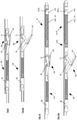
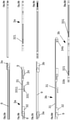
- An embodiment of the seal according to the invention has a housing 1 which has a constant cross-sectional profile over its length.
- the housing essentially has the shape of an inverted U with two legs 12 and a connecting web 11 which connects the two legs 12 to one another.
- the opposite sides 1112 of the webs 111 are slightly inclined.
- the housing can be fixed in a known manner in a groove of a door leaf.
- the attachment can be done, for example, with the help of mounting brackets, which will be discussed later.
- the person skilled in the art is familiar with various types of attachment from the prior art, in particular from published patent applications.
- the housing can be modified, for example, to have channels, webs, screw holes or other things in the housing to provide what is convenient for the attachment of the seal to a door.
- a seal also has a sealing strip.
- the sealing strip is in two parts. However, it could be in one piece or have more than two parts. Basically, any sealing strip known from the prior art can be used.
- the sealing strip comprises a rigid retaining profile 13, preferably made of aluminum, and an elastomeric sealing profile 14. In the example, both have a constant cross-sectional profile over their length.
- the holding profile 13, like the sealing profile, is essentially U-shaped in cross section.
- the retaining profile 13 and the sealing profile 14 each have a connecting web 131, 141 and two legs 132, 142 which are connected to one another via the connecting web 131, 142.
- the sealing profile 14 is fastened in locking channels 133 of the retaining profile 13 via locking webs 143 .
- two webs 134 are provided which, together with the connecting web 131, form channels whose purpose will be explained in more detail below.
- Two modules Ma, Mb are arranged in the seal, which, in the exemplary embodiment, include all parts that are used for safe movement of the sealing strip relative to the housing.
- the parts of the seal belonging to the modules Ma, Mb are partly identical in both modules. These parts can then be used in the modules Ma, Mb for the same functions of the modules Ma, Mb. Some of the modules Ma, Mb also have special functions that require special parts. functions the in the example has the first module, in another embodiment of a seal according to the invention can be perceived by the second module and vice versa. It is therefore within the scope of the invention to modify the parts of the modules Ma, Mb in such a way that they can optionally also take on fewer, different or additional functions.
- Identical or functionally similar parts of the modules Ma, Mb have reference numbers with the same numbers and are distinguished by the appended letters a and b, where a stands for parts of the first module and b for parts of the second module.
- a stands for parts of the first module
- b stands for parts of the second module.
- both modules Ma, Mb of the seal according to the invention have the function of connecting the sealing strip and the housing and, when the seal is triggered by pressing a trigger 16, converting the movement of the trigger 16 into a movement of the sealing strip relative to the housing 1.
- each module Ma, Mb has a scissor mechanism Sa, Sb.
- this scissor mechanism Sa, Sb of each module Ma, Mb in what is known as an overload situation, each module Ma, Mb also has an overload mechanism Ua, Ub.
- the modules Ma, Mb can be placed in a housing 1 at the option of a person skilled in the art.
- a seal according to the invention it is also possible for a seal according to the invention to have no housing and for the modules to be placed directly in a groove of a door. It is possible to design a seal to have only one module.
- the first module Ma includes a module housing 2a. This has an essentially constant cross-sectional profile in the shape of an inverted U. It has a connecting web 21 which connects two legs 22 of the module housing 2a. Webs 221 are attached to the insides of the legs 22 . Together with the connecting web 21, these form channels whose function will be explained below.
- the connecting web 21 protrudes beyond the outer sides of the legs 22.
- These protruding ends 211 of the connecting web are designed in such a way that they form a fit with the grooves on the facing sides 1111 of the webs 111 of the housing 1. In particular, a loose fit with a small amount of play can form during the fit.
- the module housing 2a is pushed with the ends 211 into the grooves on the mutually facing sides 1111 of the webs 111 of the housing 1 and is thus fixed in the housing at least in a form-fitting manner.
- Complete fixation can be achieved, for example, by inward deformation of the webs 111 of the housing at least at certain points, i.e. towards the ends 211 or the legs 22. As a result, parts of the webs 111 can be pressed against the ends 211 or legs 22, so that at least one non-positive connection is established.
- the ends of the module housing 2a on the release side end flush with an end of the housing 1 on the release side.
- the connecting web 21 is missing in an area on the end of the module housing on the release side 21 at the release-side end of the module housing 2a space is created to insert a mounting bracket into the housing 1.
- the short scissor element 7a of the first module Ma is structurally identical to the short scissor element 7b of the second module Mb—is essentially H-shaped. It has a connecting web 72 from which two arms 73 and two legs 74 extend. At the ends of the arms 73, which are somewhat shorter than the legs 74, are the outwardly projecting pegs 71, the function of which has already been explained. The ends of the arms 73 rest against the webs 221, which supports the arms 73 in the event of a load in the direction of the webs 221. A load on the short scissor element 7a - and thus on the pin 71 and the arms 73 - can arise when the sealing strip is pressed against a floor when it is lowered or when the sealing strip is lowered.
- the long scissor element 6a of the first module Ma - it is structurally identical to a long scissor element 6b of the second module Mb - can be divided into two sections, namely a first section 61, which forms a frame, and a second section 62, which forms a rod forms.
- the two sections 61, 62 are connected to each other.
- the second section 62 of the long scissor element 6a has two blind holes that open to the outside.
- the inwardly projecting pins 75 of the short scissor element 7a are inserted into these blind holes.
- the long and short scissor elements 6a, 7a are pivotally connected to one another.
- the second section 62 of the long scissor element 6a has a conically tapering area 621, starting from the blind holes in the direction of the free end of the second section 62. This conical narrowing of the second section 62 facilitates the assembly of the short scissor element 7a on the long scissor element 6a.
- the inwardly projecting spigots 75 of the short scissors member at the most tapered end of the taper can be placed onto the second section 62 so that the spigots lie on either side of the second section. From this end of the taper, the pins 75 can then be pushed in the direction of the blind holes. In the process, the pins 75 are bent apart until they finally engage in the blind holes.
- the free end of the first section 61 or the opening present in this first section 61 serves to guide and mount the long scissor element 6a, which will be explained in more detail below. This free end is movable to the module housing 2a.
- two outwardly projecting pins 63 are provided, which are used to connect the long scissor element 6a to the holding profile 13.
- the pins 63 are movably guided and mounted in the channels formed by the webs 134 and the connecting web 131 of the holding profile 13 .
- the second section 62 of the long scissor element 6a has a width which is no greater than the spacing of the legs 74 of the short scissor element 7a. It is thus possible for the second section 62 to be immersed between the legs 74, for example when the seal is not triggered.
- the long scissors element 6a and the short scissors element 7a together form a first scissors mechanism Sa of the first module Ma, which is also present in the second module as a second scissors mechanism Sb formed by the long scissors element 6b and the short scissors element 7b.
- the first module Ma has a sliding part 3a.
- This sliding part has a flat, rod-like section 31 which extends over the entire length of the sliding part 3a.
- This flat, rod-like section 31 has approximately the shape of a T.
- Two projecting edges 311 of the rod-like section 31 protrude into the channels that are formed by the webs 221 and the connecting web 21 of the module housing 2a. The edges 311 and thus the entire sliding part 3a are slidably guided in the channels.
- the structure 32 at an end of the sliding part 3a on the trigger side serves as a first connection structure which is provided for connecting the sliding part 3a of the first module Ma to a first connecting rod 8 . Furthermore, the structure 32 is part of the overload mechanism of the first module Ma.
- the structure 33 cooperates with the scissors mechanism Sa of the first module and is part of the overload mechanism of the first module Ma.
- the structure 34 is a second connection structure for connecting the slide part 3a of the first module Ma to a second connecting rod 9 .
- the first as well as the second connecting structure 32, 34 are designed in such a way that both tensile forces and compressive forces can be transmitted via the connecting structures 32, 34.
- the structure 33 has an arm 331 extending towards the trigger-side end, which extends parallel to the rod-like portion 31 of the sliding part 3a.
- This arm 331 reaches through the opening in the first section 61 of the long scissor element 6a of the scissor mechanism Sa of the first module Ma.
- a free end 612 of the first section 61 is thereby supported and guided between the arm 331 and the rod-like section 31 of the sliding part 3a.
- the free end 612 is held in a position between the arm 331 and the rod-like portion 31 of the slide member 3a by a holder 4a for an overload spring 5a and the overload spring 5a of the first module Ma.
- the overload spring 5a is around a helical compression spring.
- the retainer 4a for the overload spring is rod-like.
- a first portion 41 is designed to be guided between the arm 331 and the rod-like portion 31 of the slider 3a.
- the first region 41 of the holder 4a has a channel on an underside, in which a web 3311, which is provided on the upper side of the arm 331, engages.
- a free end 411 of the first portion 41 is grooved and forms a bearing shell for the free end 612 of the first portion 61 of the long scissors member 6a.
- This first area is adjoined by a second area 42, which has a larger cross-sectional area than the first area 41.
- This second area 42 forms a stop on the one hand and a first end of the overload spring 5a is supported on this second area on the other is placed on the third rod-like portion 43 of the holder 4a.
- a second end of the overload spring 5a is supported on the structure 32 of the displacement part 3a.
- the overload spring 5a presses the holder and in particular the first region 41 of the holder against the structure 33 of the sliding part. Thereby, the free end 612 of the first portion of the long scissors member 6a is held between the arm 331 and the rod-like portion 31. As shown in FIG.
- the stop function of the second area 42 of the holder 4a ensures that the overload spring 5a does not press the free end 612 of the first section 61 of the long scissor element 6a against the structure 33, which could impair easy pivoting of the long scissor element.
- the length of the first portion 41 of the holder 4a is chosen so that the free end 612 of the first section 61 of the long scissor element 6a is mounted at least with slight play between the structure 33 and the first region 41 of the holder 4a.
- a fourth area 44 adjoins the third area 43 of the holder 4a.
- This fourth area 44 is guided in a blind hole in the structure 32 .
- a lower boundary wall 321 of the blind hole has a slot open at the bottom. This slot tapers from bottom to top, i.e. from the outside in the direction of the blind hole. This makes it possible to press the fourth area 44 of the holder 4a from below through the slot into the blind hole.
- the slit is widened elastically. The fourth portion 44 of the holder 4a cannot be easily removed or fall out of the blind hole through the slot.
- the second module Mb also includes a module housing 2b.
- the module housing 2b of the second module Mb has the same cross-sectional profile as the module housing 2a of the first module. The main difference is its length.
- the module housing 2b of the second module Mb is longer than the module housing 2a of the first module Ma. This extra length is needed to accommodate a reset mechanism R.
- the reset mechanism R serves to return the seal from a deployed condition to an unactuated condition when the seal deploying force from the trigger 16 is removed.
- the second module Mb has a sliding part 3b.
- This sliding part has a flat, rod-like section 31 which extends over the entire length of the sliding part 3a and whose cross section corresponds to that of corresponding section 31 of the sliding part of the first module.
- the flat, rod-like section 31 carries three structures 32, 33b, 34b on its underside.
- the structure 32 at a trigger-side end of the slide part 3b serves as a first connection structure provided for connecting the slide part 3b of the second module Mb to the second connecting rod 9 . Furthermore, the structure 32 is part of the overload mechanism of the first module Ma. The structure is identical to the corresponding structure 32 of the sliding part 3a of the first module Ma.
- the structure 33b cooperates with the scissors mechanism Sb of the second module Mb and forms part of the overload mechanism Ub of the second module Mb. It also forms part of the return mechanism R.
- Structure 34b serves as part of the reset mechanism.
- the structure 34b could also serve as a second connection structure, which could serve to connect the sliding part 3b of the second module Mb to a further connecting rod 9, which is not provided in the exemplary embodiment, however.
- the overload mechanism Ub of the second module Mb is designed in exactly the same way as the overload mechanism Ua of the first module Ma.
- the scissors mechanism Sb of the second module Mb is also designed in the same way as the scissors mechanism Sa of the first module.
- the restoring mechanism R comprises a holder 10 for a restoring spring 15 and the restoring spring 15 as restoring spring means.
- the holder 10 has a first fork-shaped area 101 which has two pins 1011 on its outer sides. These pins 1011 are inserted into holes in the module case 2b of the second module Mb. As a result, the holder 10 cannot be displaced relative to the module housing 2b.
- This first area 101 is followed by a second area 102 onto which the return spring 15 is attached.
- the return spring 15 is a helical compression spring.
- a third area 103 also adjoins the second area. This third area is guided in a blind hole in the structure 33b of the displacement part 3b.
- a lower boundary wall 331 of the blind hole has a slot open at the bottom. This slot tapers from bottom to top, i.e. from the outside in the direction of the blind hole. This makes it possible to press the third area 103 of the holder 10 from below through the slot into the blind hole.
- the slit is widened elastically. The third portion 103 of the holder 10 cannot easily be removed or fall out of the blind hole through the slot. This secures the position of the return spring in the seal.
- the connections between the trigger 16, the first connecting rod 8, the sliding part 3a of the first module Ma, the second connecting rod 9 and the sliding part 3b of the second module Mb are subjected to pressure both when releasing and when resetting, on the one hand by the pressure, which is exerted on the trigger 12 and on the other hand by the pressure exerted by the return spring 15.
- the free ends 612 of the long scissor elements 6a, 6b moves with. As a result, these ends 612 are displaced relative to the housing 1 and the module housings 2a, 2b and the pivots 71 of the short scissor elements 7a, 7b pivotally mounted therein.
- the scissor mechanisms Sa, Sb open and the sealing strip is thereby pushed down.
- the unit consisting of the trigger 16, the first connecting rod 8, the sliding part 3a of the first module Ma, the second connecting rod 9 and the sliding part 3b of the second module Mb continues to move despite the sealing strip being stationary, this then causes the free ends 612 of the press long scissor elements 6a, 6b against the holders 4a, 4b for the overload springs 5a, 5b and move them in the direction of the trigger 16. As a result, the overload springs 5a, 5b are compressed.
- the path by which the free ends 612 can be displaced against the overload spring 5a, 5b is advantageously just as long as the distance that the unit of the trigger 16, the first connecting rod 8, the sliding part 3a of the first module Ma, the second connecting rod 9 and the sliding part 3b of the second module Mb can be shifted.
- the scissor mechanisms Sa, Sb are then protected against damage due to an overload event.
Landscapes
- Engineering & Computer Science (AREA)
- Civil Engineering (AREA)
- Structural Engineering (AREA)
- Specific Sealing Or Ventilating Devices For Doors And Windows (AREA)
- Scissors And Nippers (AREA)
- Sheet Holders (AREA)
- Sealing Devices (AREA)
Claims (11)
- Garniture d'étanchéité pour une porte, avec- un logement (1) ou un logement de module (2b),- une baguette d'étanchéité (13, 14) pouvant être abaissée,- un dispositif de déclenchement (16) permettant de déclencher un mouvement d'abaissement de la baguette d'étanchéité lorsqu'une force agit sur le dispositif de déclenchement,- une partie coulissante (3a, 3b) qui est reliée au dispositif de déclenchement (16), et- un mécanisme de retourner (R),- dans laquelle le mécanisme de retourner (R) présente des moyens formant ressort (5a, 5b, 15),caractérisée en ce que- le mécanisme de retourner (R) présente un support (10), destiné aux moyens formant ressort (15), qui a une région en forme de tige (102) qui traverse les moyens formant ressort (15) et qui comprend une région (103) guidée dans une première structure de guidage de la partie coulissante (3b), et- le support (10) du mécanisme de retourner (R) présente une région qui présente des structures de fixation (1011) qui sont fixées à le logement (1) ou à le logement de module (2b).
- Garniture d'étanchéité pour une porte, avec- une baguette d'étanchéité (13, 14) pouvant être abaissée,- un dispositif de déclenchement (16) permettant de déclencher un mouvement d'abaissement de la baguette d'étanchéité lorsqu'une force agit sur le dispositif de déclenchement,- une partie coulissante (3a, 3b) qui est reliée au dispositif de déclenchement (16), et- un mécanisme de surcharge (Ua, Ub),- dans laquelle le mécanisme de surcharge (Ua, Ub) présente des moyens formant ressort (5a, 5b),caractérisée en ce que- le mécanisme de surcharge (Ua, Ub) présente un support (4a, 4b), destiné aux moyens formant ressort (5a, 5b), qui a une région en forme de tige (43) qui traverse les moyens formant ressort (5a, 5b) et qui comprend une région (44) guidée dans une première structure de guidage de la partie coulissante (3a, 3b), et- le support (4a, 4b) du mécanisme de surcharge (Ua, Ub) présente une région (41) qui est guidée dans une seconde structure de guidage (33) de la partie coulissante (3a, 3b).
- Garniture d'étanchéité pour une porte, avec- un logement (1) ou un logement de module (2b),- une baguette d'étanchéité (13, 14) pouvant être abaissée,- un dispositif de déclenchement (16) permettant de déclencher un mouvement d'abaissement de la baguette d'étanchéité lorsqu'une force agit sur le dispositif de déclenchement,- une partie coulissante (3a, 3b) qui est reliée au dispositif de déclenchement (16), et- un mécanisme de retourner (R) et un mécanisme de surcharge (Ua, Ub),- dans laquelle le mécanisme de retourner (R) et le mécanisme de surcharge (Ua, Ub) présentent respectivement des moyens formant ressort (5a, 5b, 15),caractérisée en ce quele mécanisme de retourner (R) et le mécanisme de surcharge (Ua, Ub) présentent respectivement un support (4a, 4b, 10), destiné aux moyens formant ressort (5a, 5b, 15), qui a une région en forme de tige (43, 102) qui traverse les moyens formant ressort (5a, 5b, 15) et qui comprend une région (44, 103) qui est guidée dans une structure de guidage de la partie coulissante (3a, 3b),le support (10) du mécanisme de retourner (R) présente une région qui présente des structures de fixation (1011) qui sont fixées à le logement (1) ou à le logement de module (2b), etle support (4a, 4b) du mécanisme de surcharge (Ua, Ub) présente une région (41) qui est guidée dans une seconde structure de guidage (33) de la partie coulissante (3a, 3b).
- Garniture d'étanchéité selon l'une quelconque des revendications 1 à 3, caractérisée en ce que la région en forme de tige (43, 102) du support (4a, 4b, 10) et/ou les moyens formant ressort (5a, 5b, 15) est/sont agencé(e)(s) parallèlement à une direction de coulissement de la partie coulissante (3a, 3b).
- Garniture d'étanchéité selon l'une quelconque des revendications 1 à 4, caractérisée en ce que la structure de guidage est un évidement, en particulier un trou borgne.
- Garniture d'étanchéité selon la revendication 5, caractérisée en ce qu'une paroi de l'évidement présente une fente.
- Garniture d'étanchéité selon la revendication 6, caractérisée en ce que la fente se rétrécit au moins par sections en direction de l'évidement.
- Garniture d'étanchéité selon la revendication 7, caractérisée en ce que la fente présente dans la section rétrécie une dimension intérieure qui est inférieure à la largeur de la région (44, 103) du support (4a, 4b, 10) qui est guidée dans l'évidement.
- Garniture d'étanchéité selon la revendication 1 ou 3, caractérisée en ce que les structures de fixation (1011) du support (10) du mécanisme de retourner (R) sont des structures convexes ou saillantes, et en ce que les structures convexes ou saillantes viennent en prise dans des évidements de le logement (1) ou de le logement de module (2a, 2b).
- Garniture d'étanchéité selon la revendication 1, caractérisée en ce que la seconde structure de guidage (3) est en forme d'étrier.
- Garniture d'étanchéité selon la revendication 3 ou 10, caractérisée en ce que le support (4a, 4b) du mécanisme de surcharge (Ua, Ub) a, entre la région en forme de tige (43) qui traverse les moyens formant ressort (5a, 5b) et la région (41) qui est guidée dans la seconde structure de guidage (32), une région (42) formant une butée qui limite un mouvement du support (4a, 4b) du mécanisme de surcharge (Ua, Ub) et/ou qui forme un appui pour les moyens formant ressort (5a, 5b).
Priority Applications (9)
| Application Number | Priority Date | Filing Date | Title |
|---|---|---|---|
| EP16184708.2A EP3284897B1 (fr) | 2016-08-18 | 2016-08-18 | Joint d'étancheite comprenant une baguette d'etancheite mobile et un mecanisme de sur-course et/ou de rappel |
| PL16184708.2T PL3284897T3 (pl) | 2016-08-18 | 2016-08-18 | USZCZELKA Z DAJĄCĄ SlĘ PRZEMIESZCZAĆ LISTWĄ USZCZELNIAJĄCĄ I Z MECHANIZMEM PRZYWRACANIA l/ALBO NADMIERNEGO SKOKU |
| EP16193807.1A EP3284898B1 (fr) | 2016-08-18 | 2016-10-13 | Joint comprenant une bande d'étanchéité pouvant s'abaisser à l'aide de deux mécanismes à ciseaux |
| PL16193807.1T PL3284898T3 (pl) | 2016-08-18 | 2016-10-13 | Uszczelka z listwą uszczelniającą dającą się opuszczać za pomocą dwóch mechanizmów nożycowych |
| EP20205161.1A EP3805509B1 (fr) | 2016-08-18 | 2016-10-13 | Deuxième élément de ciseau pour un mécanisme en ciseaux pour un joint d'étanchéité |
| EP16193809.7A EP3284896B8 (fr) | 2016-08-18 | 2016-10-13 | Élément de ciseaux pour un mécanisme en ciseaux pour un joint d'étanchéité |
| EP17178820.1A EP3284899B1 (fr) | 2016-08-18 | 2017-06-29 | Joint d'étanchéité à deux modules comprenant un mécanisme à ciseaux |
| MA043429A MA43429A (fr) | 2016-08-18 | 2017-08-03 | Joint d'étanchéité doté d'un limiteur de mouvement de la lame d'étanchéité |
| EP17184657.9A EP3290627B1 (fr) | 2016-08-18 | 2017-08-03 | Joint d'étanchéité doté d'un limiteur de mouvement de la lame d'étanchéité |
Applications Claiming Priority (1)
| Application Number | Priority Date | Filing Date | Title |
|---|---|---|---|
| EP16184708.2A EP3284897B1 (fr) | 2016-08-18 | 2016-08-18 | Joint d'étancheite comprenant une baguette d'etancheite mobile et un mecanisme de sur-course et/ou de rappel |
Publications (2)
| Publication Number | Publication Date |
|---|---|
| EP3284897A1 EP3284897A1 (fr) | 2018-02-21 |
| EP3284897B1 true EP3284897B1 (fr) | 2022-03-09 |
Family
ID=56802275
Family Applications (6)
| Application Number | Title | Priority Date | Filing Date |
|---|---|---|---|
| EP16184708.2A Active EP3284897B1 (fr) | 2016-08-18 | 2016-08-18 | Joint d'étancheite comprenant une baguette d'etancheite mobile et un mecanisme de sur-course et/ou de rappel |
| EP20205161.1A Active EP3805509B1 (fr) | 2016-08-18 | 2016-10-13 | Deuxième élément de ciseau pour un mécanisme en ciseaux pour un joint d'étanchéité |
| EP16193809.7A Active EP3284896B8 (fr) | 2016-08-18 | 2016-10-13 | Élément de ciseaux pour un mécanisme en ciseaux pour un joint d'étanchéité |
| EP16193807.1A Active EP3284898B1 (fr) | 2016-08-18 | 2016-10-13 | Joint comprenant une bande d'étanchéité pouvant s'abaisser à l'aide de deux mécanismes à ciseaux |
| EP17178820.1A Active EP3284899B1 (fr) | 2016-08-18 | 2017-06-29 | Joint d'étanchéité à deux modules comprenant un mécanisme à ciseaux |
| EP17184657.9A Active EP3290627B1 (fr) | 2016-08-18 | 2017-08-03 | Joint d'étanchéité doté d'un limiteur de mouvement de la lame d'étanchéité |
Family Applications After (5)
| Application Number | Title | Priority Date | Filing Date |
|---|---|---|---|
| EP20205161.1A Active EP3805509B1 (fr) | 2016-08-18 | 2016-10-13 | Deuxième élément de ciseau pour un mécanisme en ciseaux pour un joint d'étanchéité |
| EP16193809.7A Active EP3284896B8 (fr) | 2016-08-18 | 2016-10-13 | Élément de ciseaux pour un mécanisme en ciseaux pour un joint d'étanchéité |
| EP16193807.1A Active EP3284898B1 (fr) | 2016-08-18 | 2016-10-13 | Joint comprenant une bande d'étanchéité pouvant s'abaisser à l'aide de deux mécanismes à ciseaux |
| EP17178820.1A Active EP3284899B1 (fr) | 2016-08-18 | 2017-06-29 | Joint d'étanchéité à deux modules comprenant un mécanisme à ciseaux |
| EP17184657.9A Active EP3290627B1 (fr) | 2016-08-18 | 2017-08-03 | Joint d'étanchéité doté d'un limiteur de mouvement de la lame d'étanchéité |
Country Status (3)
| Country | Link |
|---|---|
| EP (6) | EP3284897B1 (fr) |
| MA (1) | MA43429A (fr) |
| PL (2) | PL3284897T3 (fr) |
Families Citing this family (10)
| Publication number | Priority date | Publication date | Assignee | Title |
|---|---|---|---|---|
| US11326393B2 (en) * | 2018-01-23 | 2022-05-10 | Dirtt Environmental Solutions Ltd. | Door with acoustic seals |
| EP3599335B1 (fr) | 2018-07-27 | 2022-09-07 | Athmer OHG | Joint d'étanchéité abaissable, en particulier pour portes coulissantes |
| EP3699384B1 (fr) | 2019-02-20 | 2022-08-17 | Athmer oHG | Joint d'étanchéité doté d'une bande d'étanchéité pouvant être abaissée au moyen d'un mécanisme d'abaissement actionnable à l'aide d'un déclancheur |
| DK3754146T3 (da) * | 2019-06-19 | 2022-10-17 | Athmer Ohg | Automatisk tætning med dæmper til forhaling af sænkningen |
| IT201900018683A1 (it) | 2019-10-14 | 2021-04-14 | Unifor Spa | Porta con guarnizione magnetica |
| EP3859119A1 (fr) * | 2020-01-31 | 2021-08-04 | Athmer OHG | Joint d'étanchéité automatique doté d'un mécanisme de surcharge et/ou d'un mécanisme de mise à zéro doté d'un ressort doté d'un profilé d'arbre, triangulaire, de dent de scie ou d'un profilé analogue |
| EP3940183B1 (fr) | 2020-07-16 | 2023-04-19 | Athmer oHG | Moyen de guidage pour une barre de transmission dans un joint automatique et joint automatique doté d'une telle barre de transmission |
| EP4026978A1 (fr) | 2021-01-11 | 2022-07-13 | Athmer OHG | Joint d'étanchéité automatique pour une porte à double battant doté d'un revers |
| DE202022102658U1 (de) | 2022-05-13 | 2022-05-30 | Athmer Ohg | Dichtung, insbesondere für Schiebetüren oder Schiebetore |
| EP4283088A1 (fr) | 2022-05-25 | 2023-11-29 | Athmer OHG | Joint automatique d'étanchéité, en particulier pour portes anti-fumée et coupe-feu |
Citations (1)
| Publication number | Priority date | Publication date | Assignee | Title |
|---|---|---|---|---|
| DE602004009845T2 (de) * | 2003-02-21 | 2008-08-28 | Industrie- En Handelsonderneming Elton B.V. | Dichtungsanordnung für eine Tür |
Family Cites Families (8)
| Publication number | Priority date | Publication date | Assignee | Title |
|---|---|---|---|---|
| US2575459A (en) * | 1948-07-28 | 1951-11-20 | William T Moten | Weather strip structure for doors |
| CH465830A (de) | 1967-10-03 | 1968-11-30 | Arquint Joseph | Türabdichtung gegenüber einem schwellenlosen Boden |
| DE3935790C2 (de) * | 1989-10-27 | 1996-12-12 | Hahn Gmbh & Co Kg Dr | Automatische Bodendichtung für eine Tür |
| DE59200939D1 (de) * | 1991-04-17 | 1995-01-26 | Planet Mjt Ag | Dichtungsvorrichtung, insbesondere für Türflügel. |
| IT1296362B1 (it) * | 1997-11-05 | 1999-06-25 | Luigi Geron | Dispositivo paraspifferi autoregolante |
| WO2009155295A1 (fr) * | 2008-06-17 | 2009-12-23 | John B . Higman And Valorie J . Higman; Trustees Of The Higman Family Trust U/ D/T As Amended And Restated On December 22 , 2006 . | Porte et système de porte à scellement hermétique automatique |
| AU2013204610B2 (en) * | 2012-04-27 | 2015-01-22 | Raven Products Pty Ltd | A drop door seal for providing an even drop with quick fit connections with a spindle |
| DE102015000197A1 (de) * | 2015-01-15 | 2016-07-21 | Buchele Gmbh | Sicherheitstürblatt |
-
2016
- 2016-08-18 PL PL16184708.2T patent/PL3284897T3/pl unknown
- 2016-08-18 EP EP16184708.2A patent/EP3284897B1/fr active Active
- 2016-10-13 EP EP20205161.1A patent/EP3805509B1/fr active Active
- 2016-10-13 PL PL16193807.1T patent/PL3284898T3/pl unknown
- 2016-10-13 EP EP16193809.7A patent/EP3284896B8/fr active Active
- 2016-10-13 EP EP16193807.1A patent/EP3284898B1/fr active Active
-
2017
- 2017-06-29 EP EP17178820.1A patent/EP3284899B1/fr active Active
- 2017-08-03 MA MA043429A patent/MA43429A/fr unknown
- 2017-08-03 EP EP17184657.9A patent/EP3290627B1/fr active Active
Patent Citations (1)
| Publication number | Priority date | Publication date | Assignee | Title |
|---|---|---|---|---|
| DE602004009845T2 (de) * | 2003-02-21 | 2008-08-28 | Industrie- En Handelsonderneming Elton B.V. | Dichtungsanordnung für eine Tür |
Also Published As
| Publication number | Publication date |
|---|---|
| EP3290627B1 (fr) | 2026-01-07 |
| EP3284898A1 (fr) | 2018-02-21 |
| EP3805509A3 (fr) | 2021-07-21 |
| EP3284896B8 (fr) | 2022-05-18 |
| PL3284898T3 (pl) | 2022-07-18 |
| EP3284896A1 (fr) | 2018-02-21 |
| MA43429A (fr) | 2018-10-17 |
| EP3284899B1 (fr) | 2021-11-10 |
| EP3805509B1 (fr) | 2025-07-02 |
| EP3284899A1 (fr) | 2018-02-21 |
| EP3290627A1 (fr) | 2018-03-07 |
| EP3284897A1 (fr) | 2018-02-21 |
| PL3284897T3 (pl) | 2022-08-01 |
| EP3284898B1 (fr) | 2022-03-02 |
| EP3805509A2 (fr) | 2021-04-14 |
| EP3284896B1 (fr) | 2022-02-09 |
Similar Documents
| Publication | Publication Date | Title |
|---|---|---|
| EP3284897B1 (fr) | Joint d'étancheite comprenant une baguette d'etancheite mobile et un mecanisme de sur-course et/ou de rappel | |
| EP2474249B1 (fr) | Accoudoir, en particulier pour une chaise de bureau | |
| EP0436869A2 (fr) | Liaison au niveau du raccordement entre poteau et traverse d'une structure porteuse pour ou un mur de façade | |
| DE102020123253B3 (de) | Scharnier zum lösbaren und verschwenkbaren Verbinden eines Flügels mit einem Basisteil | |
| EP2264263A2 (fr) | Serrure | |
| DE102008037956B4 (de) | Betriebsmechanismus für ein bewegliches Verschlusselement | |
| EP0582258B1 (fr) | Dispositif de fixation | |
| EP2634350B1 (fr) | Joint amovible, notamment joint de porte coulissante | |
| EP3699386B1 (fr) | Joint automatique d'étanchéité de porte doté un moyen pour guider une tige de pousser et methode pour positioner ladite tige de pousser dans un bôtier pour ledit joint d'étanchéité | |
| EP3260646A1 (fr) | Escabeau comprenant un dispositif de sécurisation dans sa position déployée | |
| DE60012854T2 (de) | Panikstange | |
| EP3599335B1 (fr) | Joint d'étanchéité abaissable, en particulier pour portes coulissantes | |
| EP2439362B1 (fr) | Barre anti-panique à compression | |
| EP1717405A1 (fr) | Dispositif d'étanchéité pour porte | |
| DE4427026C2 (de) | Schubladenverriegelungsvorrichtung | |
| EP1845219A1 (fr) | Dispositif de support pour revêtements muraux | |
| DE19752619A1 (de) | Verbindungsbauteil für eine Fassadenkonstruktion und Fassadenkonstruktion | |
| DE8201832U1 (de) | Falzschere für um eine waagerechte Achse schwenkbare Flügel von Fenstern, Türen und dergleichen | |
| EP3655610B1 (fr) | Joint d'étanchéité à abaissement | |
| EP4276267B1 (fr) | Joint d'étanchéité, notamment pour portes coulissantes ou portes coulissantes | |
| EP4202171B1 (fr) | Joint automatique d'étanchéité comportant un support, des éléments de raccordement et une baguette d'étanchéité, comprenant une baguette de maintien et un élément d'étanchéité | |
| EP1611652B1 (fr) | Element de verrouillage pour fixer un appareil d'installation pour des barres omnibus | |
| DE20011070U1 (de) | Dichtungsvorrichtung für einen unteren Türspalt | |
| DE202018100133U1 (de) | Klappleiter | |
| DE202004004941U1 (de) | Auf einem Stehbolzen montierbare Stangenführung |
Legal Events
| Date | Code | Title | Description |
|---|---|---|---|
| PUAI | Public reference made under article 153(3) epc to a published international application that has entered the european phase |
Free format text: ORIGINAL CODE: 0009012 |
|
| STAA | Information on the status of an ep patent application or granted ep patent |
Free format text: STATUS: REQUEST FOR EXAMINATION WAS MADE |
|
| 17P | Request for examination filed |
Effective date: 20180112 |
|
| AK | Designated contracting states |
Kind code of ref document: A1 Designated state(s): AL AT BE BG CH CY CZ DE DK EE ES FI FR GB GR HR HU IE IS IT LI LT LU LV MC MK MT NL NO PL PT RO RS SE SI SK SM TR |
|
| AX | Request for extension of the european patent |
Extension state: BA ME |
|
| STAA | Information on the status of an ep patent application or granted ep patent |
Free format text: STATUS: EXAMINATION IS IN PROGRESS |
|
| 17Q | First examination report despatched |
Effective date: 20181109 |
|
| GRAP | Despatch of communication of intention to grant a patent |
Free format text: ORIGINAL CODE: EPIDOSNIGR1 |
|
| STAA | Information on the status of an ep patent application or granted ep patent |
Free format text: STATUS: GRANT OF PATENT IS INTENDED |
|
| INTG | Intention to grant announced |
Effective date: 20210920 |
|
| GRAS | Grant fee paid |
Free format text: ORIGINAL CODE: EPIDOSNIGR3 |
|
| GRAA | (expected) grant |
Free format text: ORIGINAL CODE: 0009210 |
|
| STAA | Information on the status of an ep patent application or granted ep patent |
Free format text: STATUS: THE PATENT HAS BEEN GRANTED |
|
| AK | Designated contracting states |
Kind code of ref document: B1 Designated state(s): AL AT BE BG CH CY CZ DE DK EE ES FI FR GB GR HR HU IE IS IT LI LT LU LV MC MK MT NL NO PL PT RO RS SE SI SK SM TR |
|
| REG | Reference to a national code |
Ref country code: GB Ref legal event code: FG4D Free format text: NOT ENGLISH |
|
| REG | Reference to a national code |
Ref country code: CH Ref legal event code: EP Ref country code: AT Ref legal event code: REF Ref document number: 1474296 Country of ref document: AT Kind code of ref document: T Effective date: 20220315 |
|
| REG | Reference to a national code |
Ref country code: DE Ref legal event code: R096 Ref document number: 502016014597 Country of ref document: DE |
|
| REG | Reference to a national code |
Ref country code: IE Ref legal event code: FG4D Free format text: LANGUAGE OF EP DOCUMENT: GERMAN |
|
| REG | Reference to a national code |
Ref country code: FI Ref legal event code: FGE |
|
| REG | Reference to a national code |
Ref country code: NL Ref legal event code: FP |
|
| REG | Reference to a national code |
Ref country code: SE Ref legal event code: TRGR |
|
| REG | Reference to a national code |
Ref country code: LT Ref legal event code: MG9D |
|
| PG25 | Lapsed in a contracting state [announced via postgrant information from national office to epo] |
Ref country code: RS Free format text: LAPSE BECAUSE OF FAILURE TO SUBMIT A TRANSLATION OF THE DESCRIPTION OR TO PAY THE FEE WITHIN THE PRESCRIBED TIME-LIMIT Effective date: 20220309 Ref country code: NO Free format text: LAPSE BECAUSE OF FAILURE TO SUBMIT A TRANSLATION OF THE DESCRIPTION OR TO PAY THE FEE WITHIN THE PRESCRIBED TIME-LIMIT Effective date: 20220609 Ref country code: LT Free format text: LAPSE BECAUSE OF FAILURE TO SUBMIT A TRANSLATION OF THE DESCRIPTION OR TO PAY THE FEE WITHIN THE PRESCRIBED TIME-LIMIT Effective date: 20220309 Ref country code: HR Free format text: LAPSE BECAUSE OF FAILURE TO SUBMIT A TRANSLATION OF THE DESCRIPTION OR TO PAY THE FEE WITHIN THE PRESCRIBED TIME-LIMIT Effective date: 20220309 Ref country code: BG Free format text: LAPSE BECAUSE OF FAILURE TO SUBMIT A TRANSLATION OF THE DESCRIPTION OR TO PAY THE FEE WITHIN THE PRESCRIBED TIME-LIMIT Effective date: 20220609 |
|
| PG25 | Lapsed in a contracting state [announced via postgrant information from national office to epo] |
Ref country code: LV Free format text: LAPSE BECAUSE OF FAILURE TO SUBMIT A TRANSLATION OF THE DESCRIPTION OR TO PAY THE FEE WITHIN THE PRESCRIBED TIME-LIMIT Effective date: 20220309 Ref country code: GR Free format text: LAPSE BECAUSE OF FAILURE TO SUBMIT A TRANSLATION OF THE DESCRIPTION OR TO PAY THE FEE WITHIN THE PRESCRIBED TIME-LIMIT Effective date: 20220610 |
|
| PG25 | Lapsed in a contracting state [announced via postgrant information from national office to epo] |
Ref country code: SM Free format text: LAPSE BECAUSE OF FAILURE TO SUBMIT A TRANSLATION OF THE DESCRIPTION OR TO PAY THE FEE WITHIN THE PRESCRIBED TIME-LIMIT Effective date: 20220309 Ref country code: SK Free format text: LAPSE BECAUSE OF FAILURE TO SUBMIT A TRANSLATION OF THE DESCRIPTION OR TO PAY THE FEE WITHIN THE PRESCRIBED TIME-LIMIT Effective date: 20220309 Ref country code: RO Free format text: LAPSE BECAUSE OF FAILURE TO SUBMIT A TRANSLATION OF THE DESCRIPTION OR TO PAY THE FEE WITHIN THE PRESCRIBED TIME-LIMIT Effective date: 20220309 Ref country code: PT Free format text: LAPSE BECAUSE OF FAILURE TO SUBMIT A TRANSLATION OF THE DESCRIPTION OR TO PAY THE FEE WITHIN THE PRESCRIBED TIME-LIMIT Effective date: 20220711 Ref country code: ES Free format text: LAPSE BECAUSE OF FAILURE TO SUBMIT A TRANSLATION OF THE DESCRIPTION OR TO PAY THE FEE WITHIN THE PRESCRIBED TIME-LIMIT Effective date: 20220309 Ref country code: EE Free format text: LAPSE BECAUSE OF FAILURE TO SUBMIT A TRANSLATION OF THE DESCRIPTION OR TO PAY THE FEE WITHIN THE PRESCRIBED TIME-LIMIT Effective date: 20220309 Ref country code: CZ Free format text: LAPSE BECAUSE OF FAILURE TO SUBMIT A TRANSLATION OF THE DESCRIPTION OR TO PAY THE FEE WITHIN THE PRESCRIBED TIME-LIMIT Effective date: 20220309 |
|
| PG25 | Lapsed in a contracting state [announced via postgrant information from national office to epo] |
Ref country code: IS Free format text: LAPSE BECAUSE OF FAILURE TO SUBMIT A TRANSLATION OF THE DESCRIPTION OR TO PAY THE FEE WITHIN THE PRESCRIBED TIME-LIMIT Effective date: 20220709 Ref country code: AL Free format text: LAPSE BECAUSE OF FAILURE TO SUBMIT A TRANSLATION OF THE DESCRIPTION OR TO PAY THE FEE WITHIN THE PRESCRIBED TIME-LIMIT Effective date: 20220309 |
|
| REG | Reference to a national code |
Ref country code: DE Ref legal event code: R097 Ref document number: 502016014597 Country of ref document: DE |
|
| PLBE | No opposition filed within time limit |
Free format text: ORIGINAL CODE: 0009261 |
|
| STAA | Information on the status of an ep patent application or granted ep patent |
Free format text: STATUS: NO OPPOSITION FILED WITHIN TIME LIMIT |
|
| PG25 | Lapsed in a contracting state [announced via postgrant information from national office to epo] |
Ref country code: DK Free format text: LAPSE BECAUSE OF FAILURE TO SUBMIT A TRANSLATION OF THE DESCRIPTION OR TO PAY THE FEE WITHIN THE PRESCRIBED TIME-LIMIT Effective date: 20220309 |
|
| 26N | No opposition filed |
Effective date: 20221212 |
|
| PG25 | Lapsed in a contracting state [announced via postgrant information from national office to epo] |
Ref country code: SI Free format text: LAPSE BECAUSE OF FAILURE TO SUBMIT A TRANSLATION OF THE DESCRIPTION OR TO PAY THE FEE WITHIN THE PRESCRIBED TIME-LIMIT Effective date: 20220309 |
|
| PG25 | Lapsed in a contracting state [announced via postgrant information from national office to epo] |
Ref country code: MC Free format text: LAPSE BECAUSE OF FAILURE TO SUBMIT A TRANSLATION OF THE DESCRIPTION OR TO PAY THE FEE WITHIN THE PRESCRIBED TIME-LIMIT Effective date: 20220309 |
|
| PG25 | Lapsed in a contracting state [announced via postgrant information from national office to epo] |
Ref country code: LU Free format text: LAPSE BECAUSE OF NON-PAYMENT OF DUE FEES Effective date: 20220818 |
|
| P01 | Opt-out of the competence of the unified patent court (upc) registered |
Effective date: 20230616 |
|
| PG25 | Lapsed in a contracting state [announced via postgrant information from national office to epo] |
Ref country code: IT Free format text: LAPSE BECAUSE OF FAILURE TO SUBMIT A TRANSLATION OF THE DESCRIPTION OR TO PAY THE FEE WITHIN THE PRESCRIBED TIME-LIMIT Effective date: 20220309 Ref country code: IE Free format text: LAPSE BECAUSE OF NON-PAYMENT OF DUE FEES Effective date: 20220818 |
|
| PGFP | Annual fee paid to national office [announced via postgrant information from national office to epo] |
Ref country code: NL Payment date: 20230821 Year of fee payment: 8 |
|
| PGFP | Annual fee paid to national office [announced via postgrant information from national office to epo] |
Ref country code: FI Payment date: 20230821 Year of fee payment: 8 |
|
| PGFP | Annual fee paid to national office [announced via postgrant information from national office to epo] |
Ref country code: SE Payment date: 20230821 Year of fee payment: 8 Ref country code: PL Payment date: 20230811 Year of fee payment: 8 Ref country code: FR Payment date: 20230825 Year of fee payment: 8 Ref country code: BE Payment date: 20230821 Year of fee payment: 8 |
|
| PG25 | Lapsed in a contracting state [announced via postgrant information from national office to epo] |
Ref country code: HU Free format text: LAPSE BECAUSE OF FAILURE TO SUBMIT A TRANSLATION OF THE DESCRIPTION OR TO PAY THE FEE WITHIN THE PRESCRIBED TIME-LIMIT; INVALID AB INITIO Effective date: 20160818 |
|
| PG25 | Lapsed in a contracting state [announced via postgrant information from national office to epo] |
Ref country code: CY Free format text: LAPSE BECAUSE OF FAILURE TO SUBMIT A TRANSLATION OF THE DESCRIPTION OR TO PAY THE FEE WITHIN THE PRESCRIBED TIME-LIMIT Effective date: 20220309 |
|
| PG25 | Lapsed in a contracting state [announced via postgrant information from national office to epo] |
Ref country code: MK Free format text: LAPSE BECAUSE OF FAILURE TO SUBMIT A TRANSLATION OF THE DESCRIPTION OR TO PAY THE FEE WITHIN THE PRESCRIBED TIME-LIMIT Effective date: 20220309 |
|
| PG25 | Lapsed in a contracting state [announced via postgrant information from national office to epo] |
Ref country code: MT Free format text: LAPSE BECAUSE OF FAILURE TO SUBMIT A TRANSLATION OF THE DESCRIPTION OR TO PAY THE FEE WITHIN THE PRESCRIBED TIME-LIMIT Effective date: 20220309 |
|
| REG | Reference to a national code |
Ref country code: SE Ref legal event code: EUG |
|
| REG | Reference to a national code |
Ref country code: NL Ref legal event code: MM Effective date: 20240901 |
|
| PG25 | Lapsed in a contracting state [announced via postgrant information from national office to epo] |
Ref country code: FI Free format text: LAPSE BECAUSE OF NON-PAYMENT OF DUE FEES Effective date: 20240818 |
|
| PG25 | Lapsed in a contracting state [announced via postgrant information from national office to epo] |
Ref country code: NL Free format text: LAPSE BECAUSE OF NON-PAYMENT OF DUE FEES Effective date: 20240901 |
|
| REG | Reference to a national code |
Ref country code: BE Ref legal event code: MM Effective date: 20240831 |
|
| PG25 | Lapsed in a contracting state [announced via postgrant information from national office to epo] |
Ref country code: BE Free format text: LAPSE BECAUSE OF NON-PAYMENT OF DUE FEES Effective date: 20240831 |
|
| PG25 | Lapsed in a contracting state [announced via postgrant information from national office to epo] |
Ref country code: FR Free format text: LAPSE BECAUSE OF NON-PAYMENT OF DUE FEES Effective date: 20240831 |
|
| PGFP | Annual fee paid to national office [announced via postgrant information from national office to epo] |
Ref country code: DE Payment date: 20250831 Year of fee payment: 10 |
|
| PG25 | Lapsed in a contracting state [announced via postgrant information from national office to epo] |
Ref country code: SE Free format text: LAPSE BECAUSE OF NON-PAYMENT OF DUE FEES Effective date: 20240819 |
|
| PGFP | Annual fee paid to national office [announced via postgrant information from national office to epo] |
Ref country code: GB Payment date: 20250821 Year of fee payment: 10 |
|
| PGFP | Annual fee paid to national office [announced via postgrant information from national office to epo] |
Ref country code: AT Payment date: 20250821 Year of fee payment: 10 |
|
| PGFP | Annual fee paid to national office [announced via postgrant information from national office to epo] |
Ref country code: CH Payment date: 20250901 Year of fee payment: 10 |
|
| PG25 | Lapsed in a contracting state [announced via postgrant information from national office to epo] |
Ref country code: TR Free format text: LAPSE BECAUSE OF FAILURE TO SUBMIT A TRANSLATION OF THE DESCRIPTION OR TO PAY THE FEE WITHIN THE PRESCRIBED TIME-LIMIT Effective date: 20220309 |