EP3284908A2 - Circuit de refroidissement pour une aube à parois multiples - Google Patents
Circuit de refroidissement pour une aube à parois multiples Download PDFInfo
- Publication number
- EP3284908A2 EP3284908A2 EP17186706.2A EP17186706A EP3284908A2 EP 3284908 A2 EP3284908 A2 EP 3284908A2 EP 17186706 A EP17186706 A EP 17186706A EP 3284908 A2 EP3284908 A2 EP 3284908A2
- Authority
- EP
- European Patent Office
- Prior art keywords
- cavity
- leading edge
- flow
- wall blade
- cooling air
- Prior art date
- Legal status (The legal status is an assumption and is not a legal conclusion. Google has not performed a legal analysis and makes no representation as to the accuracy of the status listed.)
- Granted
Links
Images


Classifications
-
- F—MECHANICAL ENGINEERING; LIGHTING; HEATING; WEAPONS; BLASTING
- F01—MACHINES OR ENGINES IN GENERAL; ENGINE PLANTS IN GENERAL; STEAM ENGINES
- F01D—NON-POSITIVE DISPLACEMENT MACHINES OR ENGINES, e.g. STEAM TURBINES
- F01D5/00—Blades; Blade-carrying members; Heating, heat-insulating, cooling or antivibration means on the blades or the members
- F01D5/12—Blades
- F01D5/14—Form or construction
- F01D5/18—Hollow blades, i.e. blades with cooling or heating channels or cavities; Heating, heat-insulating or cooling means on blades
- F01D5/187—Convection cooling
-
- F—MECHANICAL ENGINEERING; LIGHTING; HEATING; WEAPONS; BLASTING
- F01—MACHINES OR ENGINES IN GENERAL; ENGINE PLANTS IN GENERAL; STEAM ENGINES
- F01D—NON-POSITIVE DISPLACEMENT MACHINES OR ENGINES, e.g. STEAM TURBINES
- F01D25/00—Component parts, details, or accessories, not provided for in, or of interest apart from, other groups
- F01D25/08—Cooling; Heating; Heat-insulation
- F01D25/12—Cooling
-
- F—MECHANICAL ENGINEERING; LIGHTING; HEATING; WEAPONS; BLASTING
- F05—INDEXING SCHEMES RELATING TO ENGINES OR PUMPS IN VARIOUS SUBCLASSES OF CLASSES F01-F04
- F05D—INDEXING SCHEME FOR ASPECTS RELATING TO NON-POSITIVE-DISPLACEMENT MACHINES OR ENGINES, GAS-TURBINES OR JET-PROPULSION PLANTS
- F05D2250/00—Geometry
- F05D2250/10—Two-dimensional
- F05D2250/18—Two-dimensional patterned
- F05D2250/185—Two-dimensional patterned serpentine-like
-
- F—MECHANICAL ENGINEERING; LIGHTING; HEATING; WEAPONS; BLASTING
- F05—INDEXING SCHEMES RELATING TO ENGINES OR PUMPS IN VARIOUS SUBCLASSES OF CLASSES F01-F04
- F05D—INDEXING SCHEME FOR ASPECTS RELATING TO NON-POSITIVE-DISPLACEMENT MACHINES OR ENGINES, GAS-TURBINES OR JET-PROPULSION PLANTS
- F05D2260/00—Function
- F05D2260/20—Heat transfer, e.g. cooling
- F05D2260/201—Heat transfer, e.g. cooling by impingement of a fluid
-
- F—MECHANICAL ENGINEERING; LIGHTING; HEATING; WEAPONS; BLASTING
- F05—INDEXING SCHEMES RELATING TO ENGINES OR PUMPS IN VARIOUS SUBCLASSES OF CLASSES F01-F04
- F05D—INDEXING SCHEME FOR ASPECTS RELATING TO NON-POSITIVE-DISPLACEMENT MACHINES OR ENGINES, GAS-TURBINES OR JET-PROPULSION PLANTS
- F05D2260/00—Function
- F05D2260/20—Heat transfer, e.g. cooling
- F05D2260/202—Heat transfer, e.g. cooling by film cooling
Definitions
- the disclosure relates generally to turbine systems, and more particularly, to a cooling circuit for a multi-wall blade.
- Gas turbine systems are one example of turbomachines widely utilized in fields such as power generation.
- a conventional gas turbine system includes a compressor section, a combustor section, and a turbine section.
- various components in the system such as turbine blades, are subjected to high temperature flows, which can cause the components to fail. Since higher temperature flows generally result in increased performance, efficiency, and power output of a gas turbine system, it is advantageous to cool the components that are subjected to high temperature flows to allow the gas turbine system to operate at increased temperatures.
- Turbine blades typically contain an intricate maze of internal cooling channels. Cooling air provided by, for example, a compressor of a gas turbine system may be passed through the internal cooling channels to cool the turbine blades.
- Multi-wall turbine blade cooling systems may include internal near wall cooling circuits.
- Such near wall cooling circuits may include, for example, near wall cooling channels adjacent the outside walls of a multi-wall blade.
- the near wall cooling channels are typically small, requiring less cooling flow, while still maintaining enough velocity for effective cooling to occur.
- Other, typically larger, low cooling effectiveness central channels of a multi-wall blade may be used as a source of cooling air and may be used in one or more reuse circuits to collect and reroute "spent" cooling flow for redistribution to lower heat load regions of the multi-wall blade.
- a first aspect of the disclosure provides a cooling circuit for a multi-wall blade, the cooling circuit including: a pressure side cavity with a surface adjacent a pressure side of the multi-wall blade; a suction side cavity with a surface adjacent a suction side of the multi-wall blade; a central cavity disposed between the pressure side and suction side cavities, the central cavity including no surfaces adjacent the pressure and suction sides of the multi-wall blade; a first leading edge cavity with surfaces adjacent the pressure and suction sides of the multi-wall blade, the first leading edge cavity located forward of the central cavity; a second leading edge cavity located forward of the first leading edge cavity; at least one impingement opening for fluidly coupling the first leading edge cavity to the second leading edge cavity; and at least one channel for fluidly coupling the central cavity to a tip of the multi-wall blade.
- a second aspect of the disclosure provides an apparatus, including: a multi-wall turbine blade; and a cooling circuit disposed within the multi-wall turbine blade, the cooling circuit including: a pressure side cavity with a surface adjacent a pressure side of the multi-wall blade; a suction side cavity with a surface adjacent a suction side of the multi-wall blade; a central cavity disposed between the pressure side and suction side cavities, the central cavity including no surfaces adjacent the pressure and suction sides of the multi-wall blade; a first leading edge cavity with surfaces adjacent the pressure and suction sides of the multi-wall blade, the first leading edge cavity located forward of the central cavity; a second leading edge cavity located forward of the first leading edge cavity; at least one impingement opening for fluidly coupling the first leading edge cavity to the second leading edge cavity; and at least one channel for fluidly coupling the central cavity to a tip of the multi-wall blade.
- a third aspect of the disclosure provides a turbomachine, including: a gas turbine system including a compressor component, a combustor component, and a turbine component, the turbine component including a plurality of turbomachine blades, and wherein at least one of the turbomachine blades includes a multi-wall blade; and a cooling circuit disposed within the multi-wall blade, the cooling circuit including: a pressure side cavity with a surface adjacent a pressure side of the multi-wall blade; a suction side cavity with a surface adjacent a suction side of the multi-wall blade; a central cavity disposed between the pressure side and suction side cavities, the central cavity including no surfaces adjacent the pressure and suction sides of the multi-wall blade; a first leading edge cavity with surfaces adjacent the pressure and suction sides of the multi-wall blade, the first leading edge cavity located forward of the central cavity; a second leading edge cavity located forward of the first leading edge cavity; at least one impingement opening for fluidly coupling the first leading edge cavity to the second leading edge cavity; and at least one channel for
- the disclosure relates generally to turbine systems, and more particularly, to a cooling circuit for cooling a multi-wall blade.
- the "A" axis represents an axial orientation.
- the terms “axial” and/or “axially” refer to the relative position/direction of objects along axis A, which is substantially parallel with the axis of rotation of the turbomachine (in particular, the rotor section).
- the terms “radial” and/or “radially” refer to the relative position/direction of objects along an axis "r” (see, e.g., FIG. 1 ), which is substantially perpendicular with axis A and intersects axis A at only one location.
- the terms “circumferential” and/or “circumferentially” refer to the relative position/direction of objects along a circumference (c) which surrounds axis A but does not intersect the axis A at any location.
- FIG. 1 a perspective view of a turbomachine blade 2 is shown.
- the turbomachine blade 2 includes a shank 4 and a multi-wall blade 6 coupled to and extending radially outward from the shank 4.
- the multi-wall blade 6 includes a pressure side 8, an opposed suction side 10, and a tip area 38.
- the multi-wall blade 6 further includes a leading edge 14 between the pressure side 8 and the suction side 10, as well as a trailing edge 16 between the pressure side 8 and the suction side 10 on a side opposing the leading edge 14.
- the multi-wall blade 6 extends radially away from a platform 3 including a pressure side platform 5 and a suction side platform 7.
- the shank 4 and multi-wall blade 6 may each be formed of one or more metals (e.g., nickel, alloys of nickel, etc.) and may be formed (e.g., cast, forged or otherwise machined) according to conventional approaches.
- the shank 4 and multi-wall blade 6 may be integrally formed (e.g., cast, forged, three-dimensionally printed, etc.), or may be formed as separate components which are subsequently joined (e.g., via welding, brazing, bonding or other coupling mechanism).
- the multi-wall blade 6 may be a stationary blade (nozzle) or a rotatable blade.
- FIG. 2 depicts a cross-sectional view of the multi-wall blade 6 taken along line X--X of FIG. 1 .
- the multi-wall blade 6 may include a plurality of internal cavities.
- the multi-wall blade 6 includes a plurality of leading edge cavities 18A, 18B, a plurality of pressure side (outside) cavities 20A - 20D, a plurality of suction side (outside) cavities 22A - 22E, a plurality of trailing edge cavities 24A - 24C, and a plurality of central cavities 26A, 26B.
- the leading edge cavity 18B is aft of the leading edge cavity 18A (closer to the trailing edge 16).
- the number of cavities 18, 20, 22, 24, 26 within the multi-wall blade 6 may vary, of course, depending upon for example, the specific configuration, size, intended use, etc., of the multi-wall blade 6. To this extent, the number of cavities 18, 20, 22, 24, 26 shown in the embodiments disclosed herein is not meant to be limiting. According to embodiments, various cooling circuits can be provided using different combinations of the cavities 18, 20, 22, 24, 26.
- a leading edge serpentine cooling circuit 30 is depicted in FIGS. 3 and 4 . As the name indicates, the leading edge cooling circuit 30 is located adjacent the leading edge 14 of the multi-wall blade 6, between the pressure side 8 and suction side 10 of the multi-wall blade 6.
- a flow of cooling air 32 generated for example by a compressor 104 of a gas turbine system 102 ( FIG. 6 ), is fed through the shank 4 ( FIG. 1 ) to the leading edge cooling circuit 30 (e.g., via at least one cooling air feed).
- the flow of cooling air 32 is fed to a base 34 of the leading edge cavity 18B.
- the flow of cooling air 32 flows radially outward through the leading edge cavity 18B toward a tip area 38 ( FIG. 1 ) of the multi-wall blade 6, providing convection cooling.
- the leading edge cavity 18B has a surface 36 adjacent the pressure side 8 of the multi-wall blade 6, and a surface 40 adjacent the suction side 10 of the multi-wall-blade 6.
- the flow of cooling air 32 After passing into the leading edge cavity 18B, the flow of cooling air 32 is directed onto the forward wall 42 of the leading edge cavity 18A via at least one impingement hole 44, providing impingement cooling.
- a first portion 46 of the post-impingement flow of cooling air 32 flows out of the leading edge cavity 18A to the leading edge 14 of the multi-wall blade 6 via at least one film hole 48 to provide film cooling of the leading edge 14.
- a second portion 50 of the post-impingement flow of cooling air 32 is directed by a turn 52 into the pressure side cavity 20A.
- a third portion 54 of the post-impingement flow of cooling air 32 is directed by a turn 56 into the suction side cavity 22A.
- the turns 52, 56 may include a conduit, tube, pipe, channel, and/or any other suitable mechanism capable of passing air or any other gas from one location to another location within the multi-wall blade 6.
- the second portion 50 of the flow of cooling air 32 flows radially inward through the pressure side cavity 20A toward a base 58 of the pressure side cavity 20A, providing convection cooling.
- the pressure side cavity 20A includes a surface 60 adjacent the pressure side 8 of the multi-wall blade 6.
- the third portion 54 of the flow of cooling air 32 flows radially inward through the suction side cavity 22A toward a base (not shown) of the suction side cavity 22A, providing convection cooling.
- the suction side cavity 22A includes a surface 62 adjacent the suction side 10 of the multi-wall blade 6.
- a turn 64 redirects the second portion 50 of the flow of cooling air 32 from the base 58 of the pressure side cavity 20A into a base 72 of the central cavity 26A.
- Another turn redirects the third portion 54 of the flow of cooling air 32 from the base (not shown) of the suction side cavity 22A into the base 72 of the central cavity 26A.
- the second and third portions 50, 54 of the flow of cooling air 32 combine into a flow of cooling air 74, which flows radially outward through the central cavity 26A.
- the central cavity 26A has no surfaces adjacent either the pressure side 8 or the suction side 10 of the multi-wall blade 6.
- the flow of cooling air 74 flows radially outward through the central cavity 26A toward the tip area 38 ( FIG. 1 ) of the multi-wall blade 6.
- the flow of cooling air 74 flows from the central cavity 26A through at least one channel 76 and is exhausted from the tip 78 of the multi-wall blade 6 as tip film 80 to provide tip film cooling.
- the flow of cooling air 74, or portions thereof may be routed to cooling circuits in the tip 78 or the platform 3 (or inner /outer side walls) and/or may be reused in other cooling circuits aft of the leading edge serpentine cooling circuit 30.
- a flow of cooling air 132 may be fed radially inward through the leading edge cavity 18B. After passing into the leading edge cavity 18B, the flow of cooling air 132 is directed onto the forward wall 42 of the leading edge cavity 18A via at least one impingement hole 44, providing impingement cooling. A first portion 146 of the post-impingement flow of cooling air 132 flows out of the leading edge cavity 18A to the leading edge 14 of the multi-wall blade 6 via at least one film hole 48 to provide film cooling of the leading edge 14.
- a second portion 150 of the post-impingement flow of cooling air 132 is directed into the pressure side cavity 20A.
- a third portion 154 of the post-impingement flow of cooling air 132 is directed into the suction side cavity 22A.
- the second and third portions 150, 154 of the flow of cooling air 132 are directed into the central cavity 26A and combine into a flow of cooling air 174.
- the flow of cooling air 174 flows radially inward through the central cavity 26A.
- the flow of cooling air 174 is further directed through at least one channel to provide tip film.
- the flow of cooling air 174, or portions thereof may be routed to the platform 3 (or inner /outer sidewalls) and/or may be reused in other cooling circuits aft of the leading edge serpentine cooling circuit 130.
- the cooling circuits 30, 130 have been described for use in the multi-wall blade 6 of a turbomachine blade 2, which rotates during operation of a gas turbine. However, the cooling circuits 30, 130 may also be used for cooling within stationary turbine nozzles of a gas turbine. Further, the cooling circuits 30, 130 may be used to cool other structures that require an internal flow of cooling air during operation.
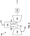
- FIG. 6 shows a schematic view of gas turbomachine 102 as may be used herein.
- the gas turbomachine 102 may include a compressor 104.
- the compressor 104 compresses an incoming flow of air 106.
- the compressor 104 delivers a flow of compressed air 108 to a combustor 110.
- the combustor 110 mixes the flow of compressed air 108 with a pressurized flow of fuel 112 and ignites the mixture to create a flow of combustion gases 114.
- the gas turbine system 102 may include any number of combustors 110.
- the flow of combustion gases 114 is in turn delivered to a turbine 116, which typically includes a plurality of the turbomachine blades 2 ( FIG. 1 ).
- the flow of combustion gases 114 drives the turbine 116 to produce mechanical work.
- the mechanical work produced in the turbine 116 drives the compressor 104 via a shaft 118, and may be used to drive an external load 120, such as an electrical generator and/or the like.
- components described as being “coupled” to one another can be joined along one or more interfaces.
- these interfaces can include junctions between distinct components, and in other cases, these interfaces can include a solidly and/or integrally formed interconnection. That is, in some cases, components that are "coupled” to one another can be simultaneously formed to define a single continuous member.
- these coupled components can be formed as separate members and be subsequently joined through known processes (e.g., fastening, ultrasonic welding, bonding).
Landscapes
- Engineering & Computer Science (AREA)
- Mechanical Engineering (AREA)
- General Engineering & Computer Science (AREA)
- Turbine Rotor Nozzle Sealing (AREA)
- Chemical & Material Sciences (AREA)
- Combustion & Propulsion (AREA)
Applications Claiming Priority (1)
| Application Number | Priority Date | Filing Date | Title |
|---|---|---|---|
| US15/239,930 US10221696B2 (en) | 2016-08-18 | 2016-08-18 | Cooling circuit for a multi-wall blade |
Publications (3)
| Publication Number | Publication Date |
|---|---|
| EP3284908A2 true EP3284908A2 (fr) | 2018-02-21 |
| EP3284908A3 EP3284908A3 (fr) | 2018-02-28 |
| EP3284908B1 EP3284908B1 (fr) | 2019-03-13 |
Family
ID=59649616
Family Applications (1)
| Application Number | Title | Priority Date | Filing Date |
|---|---|---|---|
| EP17186706.2A Active EP3284908B1 (fr) | 2016-08-18 | 2017-08-17 | Aube à parois multiples avec circuit de refroidissement |
Country Status (4)
| Country | Link |
|---|---|
| US (1) | US10221696B2 (fr) |
| EP (1) | EP3284908B1 (fr) |
| JP (1) | JP6956561B2 (fr) |
| CN (1) | CN207568658U (fr) |
Cited By (4)
| Publication number | Priority date | Publication date | Assignee | Title |
|---|---|---|---|---|
| EP3399149A1 (fr) * | 2017-05-02 | 2018-11-07 | United Technologies Corporation | Couvercles de dérivation pour une aube dans des moteurs à turbine à gaz |
| US10465528B2 (en) | 2017-02-07 | 2019-11-05 | United Technologies Corporation | Airfoil turn caps in gas turbine engines |
| US10480329B2 (en) | 2017-04-25 | 2019-11-19 | United Technologies Corporation | Airfoil turn caps in gas turbine engines |
| US10519781B2 (en) | 2017-01-12 | 2019-12-31 | United Technologies Corporation | Airfoil turn caps in gas turbine engines |
Families Citing this family (4)
| Publication number | Priority date | Publication date | Assignee | Title |
|---|---|---|---|---|
| US10060269B2 (en) | 2015-12-21 | 2018-08-28 | General Electric Company | Cooling circuits for a multi-wall blade |
| US10267162B2 (en) * | 2016-08-18 | 2019-04-23 | General Electric Company | Platform core feed for a multi-wall blade |
| FR3066530B1 (fr) * | 2017-05-22 | 2020-03-27 | Safran Aircraft Engines | Aube pour turbine de turbomachine comprenant une configuration optimisee de cavites internes de circulation d'air de refroidissement |
| CN109882247B (zh) * | 2019-04-26 | 2021-08-20 | 哈尔滨工程大学 | 一种具有通气孔内壁多通道内部冷却燃气轮机涡轮叶片 |
Family Cites Families (113)
| Publication number | Priority date | Publication date | Assignee | Title |
|---|---|---|---|---|
| US3191908A (en) * | 1961-05-02 | 1965-06-29 | Rolls Royce | Blades for fluid flow machines |
| US4474532A (en) | 1981-12-28 | 1984-10-02 | United Technologies Corporation | Coolable airfoil for a rotary machine |
| GB2121483B (en) | 1982-06-08 | 1985-02-13 | Rolls Royce | Cooled turbine blade for a gas turbine engine |
| US4650399A (en) | 1982-06-14 | 1987-03-17 | United Technologies Corporation | Rotor blade for a rotary machine |
| US4753575A (en) | 1987-08-06 | 1988-06-28 | United Technologies Corporation | Airfoil with nested cooling channels |
| SG46261A1 (en) | 1990-04-09 | 1998-02-20 | Commw Scient Ind Res Org | A detection system for use in an aircraft |
| US5813835A (en) * | 1991-08-19 | 1998-09-29 | The United States Of America As Represented By The Secretary Of The Air Force | Air-cooled turbine blade |
| US5296308A (en) | 1992-08-10 | 1994-03-22 | Howmet Corporation | Investment casting using core with integral wall thickness control means |
| US5356265A (en) | 1992-08-25 | 1994-10-18 | General Electric Company | Chordally bifurcated turbine blade |
| US5382135A (en) | 1992-11-24 | 1995-01-17 | United Technologies Corporation | Rotor blade with cooled integral platform |
| US5403159A (en) | 1992-11-30 | 1995-04-04 | United Technoligies Corporation | Coolable airfoil structure |
| US5702232A (en) | 1994-12-13 | 1997-12-30 | United Technologies Corporation | Cooled airfoils for a gas turbine engine |
| US5853044A (en) | 1996-04-24 | 1998-12-29 | Pcc Airfoils, Inc. | Method of casting an article |
| JP3411775B2 (ja) | 1997-03-10 | 2003-06-03 | 三菱重工業株式会社 | ガスタービン動翼 |
| US6220817B1 (en) | 1997-11-17 | 2001-04-24 | General Electric Company | AFT flowing multi-tier airfoil cooling circuit |
| GB9901218D0 (en) | 1999-01-21 | 1999-03-10 | Rolls Royce Plc | Cooled aerofoil for a gas turbine engine |
| US6196792B1 (en) | 1999-01-29 | 2001-03-06 | General Electric Company | Preferentially cooled turbine shroud |
| US6168381B1 (en) | 1999-06-29 | 2001-01-02 | General Electric Company | Airfoil isolated leading edge cooling |
| US6416284B1 (en) | 2000-11-03 | 2002-07-09 | General Electric Company | Turbine blade for gas turbine engine and method of cooling same |
| JP2002242607A (ja) | 2001-02-20 | 2002-08-28 | Mitsubishi Heavy Ind Ltd | ガスタービン冷却翼 |
| US6491496B2 (en) | 2001-02-23 | 2002-12-10 | General Electric Company | Turbine airfoil with metering plates for refresher holes |
| US6478535B1 (en) | 2001-05-04 | 2002-11-12 | Honeywell International, Inc. | Thin wall cooling system |
| FR2829174B1 (fr) | 2001-08-28 | 2006-01-20 | Snecma Moteurs | Perfectionnement apportes aux circuits de refroidissement pour aube de turbine a gaz |
| FR2829175B1 (fr) | 2001-08-28 | 2003-11-07 | Snecma Moteurs | Circuits de refroidissement pour aube de turbine a gaz |
| US6974308B2 (en) | 2001-11-14 | 2005-12-13 | Honeywell International, Inc. | High effectiveness cooled turbine vane or blade |
| US6746209B2 (en) | 2002-05-31 | 2004-06-08 | General Electric Company | Methods and apparatus for cooling gas turbine engine nozzle assemblies |
| US6832889B1 (en) | 2003-07-09 | 2004-12-21 | General Electric Company | Integrated bridge turbine blade |
| US7104757B2 (en) | 2003-07-29 | 2006-09-12 | Siemens Aktiengesellschaft | Cooled turbine blade |
| US6955525B2 (en) | 2003-08-08 | 2005-10-18 | Siemens Westinghouse Power Corporation | Cooling system for an outer wall of a turbine blade |
| US6887033B1 (en) | 2003-11-10 | 2005-05-03 | General Electric Company | Cooling system for nozzle segment platform edges |
| US7097426B2 (en) | 2004-04-08 | 2006-08-29 | General Electric Company | Cascade impingement cooled airfoil |
| US7217097B2 (en) | 2005-01-07 | 2007-05-15 | Siemens Power Generation, Inc. | Cooling system with internal flow guide within a turbine blade of a turbine engine |
| US7413407B2 (en) | 2005-03-29 | 2008-08-19 | Siemens Power Generation, Inc. | Turbine blade cooling system with bifurcated mid-chord cooling chamber |
| US7303376B2 (en) | 2005-12-02 | 2007-12-04 | Siemens Power Generation, Inc. | Turbine airfoil with outer wall cooling system and inner mid-chord hot gas receiving cavity |
| US7296973B2 (en) | 2005-12-05 | 2007-11-20 | General Electric Company | Parallel serpentine cooled blade |
| US7513738B2 (en) | 2006-02-15 | 2009-04-07 | General Electric Company | Methods and apparatus for cooling gas turbine rotor blades |
| US7416391B2 (en) | 2006-02-24 | 2008-08-26 | General Electric Company | Bucket platform cooling circuit and method |
| US7686581B2 (en) | 2006-06-07 | 2010-03-30 | General Electric Company | Serpentine cooling circuit and method for cooling tip shroud |
| US7458778B1 (en) * | 2006-06-14 | 2008-12-02 | Florida Turbine Technologies, Inc. | Turbine airfoil with a bifurcated counter flow serpentine path |
| US7534089B2 (en) | 2006-07-18 | 2009-05-19 | Siemens Energy, Inc. | Turbine airfoil with near wall multi-serpentine cooling channels |
| US7780413B2 (en) | 2006-08-01 | 2010-08-24 | Siemens Energy, Inc. | Turbine airfoil with near wall inflow chambers |
| US7527475B1 (en) | 2006-08-11 | 2009-05-05 | Florida Turbine Technologies, Inc. | Turbine blade with a near-wall cooling circuit |
| US7527474B1 (en) | 2006-08-11 | 2009-05-05 | Florida Turbine Technologies, Inc. | Turbine airfoil with mini-serpentine cooling passages |
| US7481623B1 (en) | 2006-08-11 | 2009-01-27 | Florida Turbine Technologies, Inc. | Compartment cooled turbine blade |
| US7625178B2 (en) | 2006-08-30 | 2009-12-01 | Honeywell International Inc. | High effectiveness cooled turbine blade |
| US7722324B2 (en) | 2006-09-05 | 2010-05-25 | United Technologies Corporation | Multi-peripheral serpentine microcircuits for high aspect ratio blades |
| US7607891B2 (en) | 2006-10-23 | 2009-10-27 | United Technologies Corporation | Turbine component with tip flagged pedestal cooling |
| US8591189B2 (en) | 2006-11-20 | 2013-11-26 | General Electric Company | Bifeed serpentine cooled blade |
| US7914257B1 (en) | 2007-01-17 | 2011-03-29 | Florida Turbine Technologies, Inc. | Turbine rotor blade with spiral and serpentine flow cooling circuit |
| US8047790B1 (en) | 2007-01-17 | 2011-11-01 | Florida Turbine Technologies, Inc. | Near wall compartment cooled turbine blade |
| US7845906B2 (en) | 2007-01-24 | 2010-12-07 | United Technologies Corporation | Dual cut-back trailing edge for airfoils |
| US7780415B2 (en) | 2007-02-15 | 2010-08-24 | Siemens Energy, Inc. | Turbine blade having a convergent cavity cooling system for a trailing edge |
| US7819629B2 (en) | 2007-02-15 | 2010-10-26 | Siemens Energy, Inc. | Blade for a gas turbine |
| JP5281245B2 (ja) | 2007-02-21 | 2013-09-04 | 三菱重工業株式会社 | ガスタービン動翼のプラットフォーム冷却構造 |
| US7862299B1 (en) | 2007-03-21 | 2011-01-04 | Florida Turbine Technologies, Inc. | Two piece hollow turbine blade with serpentine cooling circuits |
| KR100900231B1 (ko) | 2007-06-21 | 2009-06-02 | 주식회사 하이닉스반도체 | 반도체 소자의 제조방법 |
| US7845907B2 (en) | 2007-07-23 | 2010-12-07 | United Technologies Corporation | Blade cooling passage for a turbine engine |
| US7785072B1 (en) | 2007-09-07 | 2010-08-31 | Florida Turbine Technologies, Inc. | Large chord turbine vane with serpentine flow cooling circuit |
| US7857589B1 (en) | 2007-09-21 | 2010-12-28 | Florida Turbine Technologies, Inc. | Turbine airfoil with near-wall cooling |
| US8292581B2 (en) | 2008-01-09 | 2012-10-23 | Honeywell International Inc. | Air cooled turbine blades and methods of manufacturing |
| US7901183B1 (en) | 2008-01-22 | 2011-03-08 | Florida Turbine Technologies, Inc. | Turbine blade with dual aft flowing triple pass serpentines |
| US8087891B1 (en) | 2008-01-23 | 2012-01-03 | Florida Turbine Technologies, Inc. | Turbine blade with tip region cooling |
| US8057183B1 (en) | 2008-12-16 | 2011-11-15 | Florida Turbine Technologies, Inc. | Light weight and highly cooled turbine blade |
| US8011888B1 (en) | 2009-04-18 | 2011-09-06 | Florida Turbine Technologies, Inc. | Turbine blade with serpentine cooling |
| US8157505B2 (en) | 2009-05-12 | 2012-04-17 | Siemens Energy, Inc. | Turbine blade with single tip rail with a mid-positioned deflector portion |
| US8292582B1 (en) | 2009-07-09 | 2012-10-23 | Florida Turbine Technologies, Inc. | Turbine blade with serpentine flow cooling |
| GB0917319D0 (en) | 2009-10-05 | 2009-11-18 | Rolls Royce Plc | An apparatus and method of operating a gas turbine engine |
| US8356978B2 (en) | 2009-11-23 | 2013-01-22 | United Technologies Corporation | Turbine airfoil platform cooling core |
| US8444386B1 (en) | 2010-01-19 | 2013-05-21 | Florida Turbine Technologies, Inc. | Turbine blade with multiple near wall serpentine flow cooling |
| US8535004B2 (en) | 2010-03-26 | 2013-09-17 | Siemens Energy, Inc. | Four-wall turbine airfoil with thermal strain control for reduced cycle fatigue |
| US8616845B1 (en) | 2010-06-23 | 2013-12-31 | Florida Turbine Technologies, Inc. | Turbine blade with tip cooling circuit |
| US8471730B2 (en) | 2010-09-16 | 2013-06-25 | The Boeing Company | Systems and methods for early detection of aircraft approach to volcanic plume |
| US8794921B2 (en) | 2010-09-30 | 2014-08-05 | General Electric Company | Apparatus and methods for cooling platform regions of turbine rotor blades |
| US8666570B1 (en) | 2010-11-19 | 2014-03-04 | The Boeing Company | Volcanic ash detection by optical backscatter using standard aircraft lights |
| US9022736B2 (en) * | 2011-02-15 | 2015-05-05 | Siemens Energy, Inc. | Integrated axial and tangential serpentine cooling circuit in a turbine airfoil |
| US8459103B2 (en) | 2011-06-24 | 2013-06-11 | United Technologies Corporation | IDMS signal processing to distinguish inlet particulates |
| US9010198B2 (en) | 2011-07-29 | 2015-04-21 | United Technologies Corporation | Aircraft debris monitoring sensor assembly |
| GB201113478D0 (en) | 2011-08-04 | 2011-09-21 | Cambridge Entpr Ltd | Sensing systems |
| US8734108B1 (en) | 2011-11-22 | 2014-05-27 | Florida Turbine Technologies, Inc. | Turbine blade with impingement cooling cavities and platform cooling channels connected in series |
| US9249673B2 (en) | 2011-12-30 | 2016-02-02 | General Electric Company | Turbine rotor blade platform cooling |
| US8869603B2 (en) | 2012-02-29 | 2014-10-28 | United Technologies Corporation | Debris detection in turbomachinery and gas turbine engines |
| US8678766B1 (en) | 2012-07-02 | 2014-03-25 | Florida Turbine Technologies, Inc. | Turbine blade with near wall cooling channels |
| US9557308B2 (en) | 2012-08-21 | 2017-01-31 | University Of Alaska Fairbanks | Rapid response volcanic ash detector |
| US20140096538A1 (en) | 2012-10-05 | 2014-04-10 | General Electric Company | Platform cooling of a turbine blade assembly |
| WO2014091415A1 (fr) | 2012-12-12 | 2014-06-19 | Actelion Pharmaceuticals Ltd | Dérivés d'indole carboxamide utilisés en tant qu'antagonistes du récepteur p2x7 |
| US9222873B2 (en) | 2013-05-02 | 2015-12-29 | Droplet Measurement Technologies, Inc. | Optical particle detector |
| US9366194B2 (en) | 2013-09-05 | 2016-06-14 | General Electric Company | Method and system for controlling gas turbine performance with a variable backflow margin |
| US9041926B2 (en) | 2013-09-06 | 2015-05-26 | Rosemount Aerospace Inc. | Apparatus and method for in-flight detection of airborne volcanic ash |
| US9670784B2 (en) | 2013-10-23 | 2017-06-06 | General Electric Company | Turbine bucket base having serpentine cooling passage with leading edge cooling |
| US9995149B2 (en) | 2013-12-30 | 2018-06-12 | General Electric Company | Structural configurations and cooling circuits in turbine blades |
| US20150184538A1 (en) | 2013-12-30 | 2015-07-02 | General Electric Company | Interior cooling circuits in turbine blades |
| GB2522917A (en) | 2014-02-11 | 2015-08-12 | Sss Steel Profiles Ltd | Ladder brace |
| DE112015003047B4 (de) | 2014-06-30 | 2021-08-26 | Mitsubishi Power, Ltd. | Turbinenleitschaufel, turbine und verfahren zum modifizieren einer turbinenleitschaufel |
| US10294799B2 (en) | 2014-11-12 | 2019-05-21 | United Technologies Corporation | Partial tip flag |
| US9845694B2 (en) | 2015-04-22 | 2017-12-19 | United Technologies Corporation | Flow directing cover for engine component |
| US9863538B2 (en) | 2015-04-27 | 2018-01-09 | United Technologies Corporation | Gas turbine engine brush seal with supported tip |
| US10054055B2 (en) | 2015-11-19 | 2018-08-21 | United Technology Corporation | Serpentine platform cooling structures |
| US10017844B2 (en) | 2015-12-18 | 2018-07-10 | General Electric Company | Coated articles and method for making |
| US9976425B2 (en) | 2015-12-21 | 2018-05-22 | General Electric Company | Cooling circuit for a multi-wall blade |
| US10030526B2 (en) | 2015-12-21 | 2018-07-24 | General Electric Company | Platform core feed for a multi-wall blade |
| US10119405B2 (en) | 2015-12-21 | 2018-11-06 | General Electric Company | Cooling circuit for a multi-wall blade |
| US10053989B2 (en) | 2015-12-21 | 2018-08-21 | General Electric Company | Cooling circuit for a multi-wall blade |
| US9932838B2 (en) | 2015-12-21 | 2018-04-03 | General Electric Company | Cooling circuit for a multi-wall blade |
| US20170175544A1 (en) | 2015-12-21 | 2017-06-22 | General Electric Company | Cooling circuits for a multi-wall blade |
| US10052683B2 (en) | 2015-12-21 | 2018-08-21 | General Electric Company | Center plenum support for a multiwall turbine airfoil casting |
| US10060269B2 (en) | 2015-12-21 | 2018-08-28 | General Electric Company | Cooling circuits for a multi-wall blade |
| US9926788B2 (en) | 2015-12-21 | 2018-03-27 | General Electric Company | Cooling circuit for a multi-wall blade |
| US9938836B2 (en) | 2015-12-22 | 2018-04-10 | General Electric Company | Turbine airfoil with trailing edge cooling circuit |
| US9909427B2 (en) | 2015-12-22 | 2018-03-06 | General Electric Company | Turbine airfoil with trailing edge cooling circuit |
| US10208607B2 (en) | 2016-08-18 | 2019-02-19 | General Electric Company | Cooling circuit for a multi-wall blade |
| US10208608B2 (en) | 2016-08-18 | 2019-02-19 | General Electric Company | Cooling circuit for a multi-wall blade |
| US10227877B2 (en) | 2016-08-18 | 2019-03-12 | General Electric Company | Cooling circuit for a multi-wall blade |
| US10267162B2 (en) | 2016-08-18 | 2019-04-23 | General Electric Company | Platform core feed for a multi-wall blade |
-
2016
- 2016-08-18 US US15/239,930 patent/US10221696B2/en active Active
-
2017
- 2017-08-10 JP JP2017154872A patent/JP6956561B2/ja active Active
- 2017-08-17 EP EP17186706.2A patent/EP3284908B1/fr active Active
- 2017-08-18 CN CN201721038391.1U patent/CN207568658U/zh active Active
Cited By (5)
| Publication number | Priority date | Publication date | Assignee | Title |
|---|---|---|---|---|
| US10519781B2 (en) | 2017-01-12 | 2019-12-31 | United Technologies Corporation | Airfoil turn caps in gas turbine engines |
| US10465528B2 (en) | 2017-02-07 | 2019-11-05 | United Technologies Corporation | Airfoil turn caps in gas turbine engines |
| US10480329B2 (en) | 2017-04-25 | 2019-11-19 | United Technologies Corporation | Airfoil turn caps in gas turbine engines |
| EP3399149A1 (fr) * | 2017-05-02 | 2018-11-07 | United Technologies Corporation | Couvercles de dérivation pour une aube dans des moteurs à turbine à gaz |
| US10267163B2 (en) | 2017-05-02 | 2019-04-23 | United Technologies Corporation | Airfoil turn caps in gas turbine engines |
Also Published As
| Publication number | Publication date |
|---|---|
| CN207568658U (zh) | 2018-07-03 |
| EP3284908A3 (fr) | 2018-02-28 |
| US20180051573A1 (en) | 2018-02-22 |
| JP6956561B2 (ja) | 2021-11-02 |
| EP3284908B1 (fr) | 2019-03-13 |
| JP2018048627A (ja) | 2018-03-29 |
| US10221696B2 (en) | 2019-03-05 |
Similar Documents
| Publication | Publication Date | Title |
|---|---|---|
| EP3284908B1 (fr) | Aube à parois multiples avec circuit de refroidissement | |
| US10781698B2 (en) | Cooling circuits for a multi-wall blade | |
| EP3184741B1 (fr) | Circuit de refroidissement pour aube à parois multiples | |
| US10053989B2 (en) | Cooling circuit for a multi-wall blade | |
| US9926788B2 (en) | Cooling circuit for a multi-wall blade | |
| EP3184744A1 (fr) | Circuits de refroidissement pour aube à parois multiples | |
| EP3184737B1 (fr) | Aube à parois multiples avec circuit de refroidissement | |
| EP3315726B1 (fr) | Circuits de refroidissement de bord de fuite partiellement enveloppés comportant des impacts côté pression | |
| EP3336311B1 (fr) | Aube de turbomachine comportant un circuit de refroidissement de bord de fuite | |
| EP3244009B1 (fr) | Alimentation centrale de plate-forme pour une aube à parois multiples | |
| EP3284907B1 (fr) | Aube à parois multiples avec plateforme refroidie | |
| EP3336310B1 (fr) | Circuit de refroidissement de bord arrière partiellement enveloppé avec cavités en serpentin côté pression | |
| US10208607B2 (en) | Cooling circuit for a multi-wall blade | |
| US10208608B2 (en) | Cooling circuit for a multi-wall blade | |
| US10227877B2 (en) | Cooling circuit for a multi-wall blade |
Legal Events
| Date | Code | Title | Description |
|---|---|---|---|
| PUAI | Public reference made under article 153(3) epc to a published international application that has entered the european phase |
Free format text: ORIGINAL CODE: 0009012 |
|
| STAA | Information on the status of an ep patent application or granted ep patent |
Free format text: STATUS: THE APPLICATION HAS BEEN PUBLISHED |
|
| PUAL | Search report despatched |
Free format text: ORIGINAL CODE: 0009013 |
|
| AK | Designated contracting states |
Kind code of ref document: A2 Designated state(s): AL AT BE BG CH CY CZ DE DK EE ES FI FR GB GR HR HU IE IS IT LI LT LU LV MC MK MT NL NO PL PT RO RS SE SI SK SM TR |
|
| AX | Request for extension of the european patent |
Extension state: BA ME |
|
| AK | Designated contracting states |
Kind code of ref document: A3 Designated state(s): AL AT BE BG CH CY CZ DE DK EE ES FI FR GB GR HR HU IE IS IT LI LT LU LV MC MK MT NL NO PL PT RO RS SE SI SK SM TR |
|
| AX | Request for extension of the european patent |
Extension state: BA ME |
|
| RIC1 | Information provided on ipc code assigned before grant |
Ipc: F01D 5/18 20060101AFI20180123BHEP |
|
| STAA | Information on the status of an ep patent application or granted ep patent |
Free format text: STATUS: REQUEST FOR EXAMINATION WAS MADE |
|
| 17P | Request for examination filed |
Effective date: 20180828 |
|
| RBV | Designated contracting states (corrected) |
Designated state(s): AL AT BE BG CH CY CZ DE DK EE ES FI FR GB GR HR HU IE IS IT LI LT LU LV MC MK MT NL NO PL PT RO RS SE SI SK SM TR |
|
| GRAP | Despatch of communication of intention to grant a patent |
Free format text: ORIGINAL CODE: EPIDOSNIGR1 |
|
| STAA | Information on the status of an ep patent application or granted ep patent |
Free format text: STATUS: GRANT OF PATENT IS INTENDED |
|
| INTG | Intention to grant announced |
Effective date: 20181029 |
|
| GRAS | Grant fee paid |
Free format text: ORIGINAL CODE: EPIDOSNIGR3 |
|
| GRAA | (expected) grant |
Free format text: ORIGINAL CODE: 0009210 |
|
| STAA | Information on the status of an ep patent application or granted ep patent |
Free format text: STATUS: THE PATENT HAS BEEN GRANTED |
|
| AK | Designated contracting states |
Kind code of ref document: B1 Designated state(s): AL AT BE BG CH CY CZ DE DK EE ES FI FR GB GR HR HU IE IS IT LI LT LU LV MC MK MT NL NO PL PT RO RS SE SI SK SM TR |
|
| REG | Reference to a national code |
Ref country code: GB Ref legal event code: FG4D |
|
| REG | Reference to a national code |
Ref country code: CH Ref legal event code: EP Ref country code: AT Ref legal event code: REF Ref document number: 1107940 Country of ref document: AT Kind code of ref document: T Effective date: 20190315 |
|
| REG | Reference to a national code |
Ref country code: IE Ref legal event code: FG4D |
|
| REG | Reference to a national code |
Ref country code: DE Ref legal event code: R096 Ref document number: 602017002686 Country of ref document: DE |
|
| REG | Reference to a national code |
Ref country code: NL Ref legal event code: MP Effective date: 20190313 |
|
| REG | Reference to a national code |
Ref country code: LT Ref legal event code: MG4D |
|
| PG25 | Lapsed in a contracting state [announced via postgrant information from national office to epo] |
Ref country code: SE Free format text: LAPSE BECAUSE OF FAILURE TO SUBMIT A TRANSLATION OF THE DESCRIPTION OR TO PAY THE FEE WITHIN THE PRESCRIBED TIME-LIMIT Effective date: 20190313 Ref country code: NO Free format text: LAPSE BECAUSE OF FAILURE TO SUBMIT A TRANSLATION OF THE DESCRIPTION OR TO PAY THE FEE WITHIN THE PRESCRIBED TIME-LIMIT Effective date: 20190613 Ref country code: LT Free format text: LAPSE BECAUSE OF FAILURE TO SUBMIT A TRANSLATION OF THE DESCRIPTION OR TO PAY THE FEE WITHIN THE PRESCRIBED TIME-LIMIT Effective date: 20190313 Ref country code: FI Free format text: LAPSE BECAUSE OF FAILURE TO SUBMIT A TRANSLATION OF THE DESCRIPTION OR TO PAY THE FEE WITHIN THE PRESCRIBED TIME-LIMIT Effective date: 20190313 |
|
| PG25 | Lapsed in a contracting state [announced via postgrant information from national office to epo] |
Ref country code: NL Free format text: LAPSE BECAUSE OF FAILURE TO SUBMIT A TRANSLATION OF THE DESCRIPTION OR TO PAY THE FEE WITHIN THE PRESCRIBED TIME-LIMIT Effective date: 20190313 Ref country code: HR Free format text: LAPSE BECAUSE OF FAILURE TO SUBMIT A TRANSLATION OF THE DESCRIPTION OR TO PAY THE FEE WITHIN THE PRESCRIBED TIME-LIMIT Effective date: 20190313 Ref country code: LV Free format text: LAPSE BECAUSE OF FAILURE TO SUBMIT A TRANSLATION OF THE DESCRIPTION OR TO PAY THE FEE WITHIN THE PRESCRIBED TIME-LIMIT Effective date: 20190313 Ref country code: GR Free format text: LAPSE BECAUSE OF FAILURE TO SUBMIT A TRANSLATION OF THE DESCRIPTION OR TO PAY THE FEE WITHIN THE PRESCRIBED TIME-LIMIT Effective date: 20190614 Ref country code: BG Free format text: LAPSE BECAUSE OF FAILURE TO SUBMIT A TRANSLATION OF THE DESCRIPTION OR TO PAY THE FEE WITHIN THE PRESCRIBED TIME-LIMIT Effective date: 20190613 Ref country code: RS Free format text: LAPSE BECAUSE OF FAILURE TO SUBMIT A TRANSLATION OF THE DESCRIPTION OR TO PAY THE FEE WITHIN THE PRESCRIBED TIME-LIMIT Effective date: 20190313 |
|
| REG | Reference to a national code |
Ref country code: AT Ref legal event code: MK05 Ref document number: 1107940 Country of ref document: AT Kind code of ref document: T Effective date: 20190313 |
|
| PG25 | Lapsed in a contracting state [announced via postgrant information from national office to epo] |
Ref country code: EE Free format text: LAPSE BECAUSE OF FAILURE TO SUBMIT A TRANSLATION OF THE DESCRIPTION OR TO PAY THE FEE WITHIN THE PRESCRIBED TIME-LIMIT Effective date: 20190313 Ref country code: ES Free format text: LAPSE BECAUSE OF FAILURE TO SUBMIT A TRANSLATION OF THE DESCRIPTION OR TO PAY THE FEE WITHIN THE PRESCRIBED TIME-LIMIT Effective date: 20190313 Ref country code: RO Free format text: LAPSE BECAUSE OF FAILURE TO SUBMIT A TRANSLATION OF THE DESCRIPTION OR TO PAY THE FEE WITHIN THE PRESCRIBED TIME-LIMIT Effective date: 20190313 Ref country code: CZ Free format text: LAPSE BECAUSE OF FAILURE TO SUBMIT A TRANSLATION OF THE DESCRIPTION OR TO PAY THE FEE WITHIN THE PRESCRIBED TIME-LIMIT Effective date: 20190313 Ref country code: IT Free format text: LAPSE BECAUSE OF FAILURE TO SUBMIT A TRANSLATION OF THE DESCRIPTION OR TO PAY THE FEE WITHIN THE PRESCRIBED TIME-LIMIT Effective date: 20190313 Ref country code: AL Free format text: LAPSE BECAUSE OF FAILURE TO SUBMIT A TRANSLATION OF THE DESCRIPTION OR TO PAY THE FEE WITHIN THE PRESCRIBED TIME-LIMIT Effective date: 20190313 Ref country code: PT Free format text: LAPSE BECAUSE OF FAILURE TO SUBMIT A TRANSLATION OF THE DESCRIPTION OR TO PAY THE FEE WITHIN THE PRESCRIBED TIME-LIMIT Effective date: 20190713 Ref country code: SK Free format text: LAPSE BECAUSE OF FAILURE TO SUBMIT A TRANSLATION OF THE DESCRIPTION OR TO PAY THE FEE WITHIN THE PRESCRIBED TIME-LIMIT Effective date: 20190313 |
|
| PG25 | Lapsed in a contracting state [announced via postgrant information from national office to epo] |
Ref country code: PL Free format text: LAPSE BECAUSE OF FAILURE TO SUBMIT A TRANSLATION OF THE DESCRIPTION OR TO PAY THE FEE WITHIN THE PRESCRIBED TIME-LIMIT Effective date: 20190313 Ref country code: SM Free format text: LAPSE BECAUSE OF FAILURE TO SUBMIT A TRANSLATION OF THE DESCRIPTION OR TO PAY THE FEE WITHIN THE PRESCRIBED TIME-LIMIT Effective date: 20190313 |
|
| REG | Reference to a national code |
Ref country code: DE Ref legal event code: R097 Ref document number: 602017002686 Country of ref document: DE |
|
| PG25 | Lapsed in a contracting state [announced via postgrant information from national office to epo] |
Ref country code: AT Free format text: LAPSE BECAUSE OF FAILURE TO SUBMIT A TRANSLATION OF THE DESCRIPTION OR TO PAY THE FEE WITHIN THE PRESCRIBED TIME-LIMIT Effective date: 20190313 Ref country code: IS Free format text: LAPSE BECAUSE OF FAILURE TO SUBMIT A TRANSLATION OF THE DESCRIPTION OR TO PAY THE FEE WITHIN THE PRESCRIBED TIME-LIMIT Effective date: 20190713 |
|
| PLBE | No opposition filed within time limit |
Free format text: ORIGINAL CODE: 0009261 |
|
| STAA | Information on the status of an ep patent application or granted ep patent |
Free format text: STATUS: NO OPPOSITION FILED WITHIN TIME LIMIT |
|
| PG25 | Lapsed in a contracting state [announced via postgrant information from national office to epo] |
Ref country code: DK Free format text: LAPSE BECAUSE OF FAILURE TO SUBMIT A TRANSLATION OF THE DESCRIPTION OR TO PAY THE FEE WITHIN THE PRESCRIBED TIME-LIMIT Effective date: 20190313 |
|
| 26N | No opposition filed |
Effective date: 20191216 |
|
| PG25 | Lapsed in a contracting state [announced via postgrant information from national office to epo] |
Ref country code: SI Free format text: LAPSE BECAUSE OF FAILURE TO SUBMIT A TRANSLATION OF THE DESCRIPTION OR TO PAY THE FEE WITHIN THE PRESCRIBED TIME-LIMIT Effective date: 20190313 |
|
| PG25 | Lapsed in a contracting state [announced via postgrant information from national office to epo] |
Ref country code: TR Free format text: LAPSE BECAUSE OF FAILURE TO SUBMIT A TRANSLATION OF THE DESCRIPTION OR TO PAY THE FEE WITHIN THE PRESCRIBED TIME-LIMIT Effective date: 20190313 |
|
| PG25 | Lapsed in a contracting state [announced via postgrant information from national office to epo] |
Ref country code: MC Free format text: LAPSE BECAUSE OF FAILURE TO SUBMIT A TRANSLATION OF THE DESCRIPTION OR TO PAY THE FEE WITHIN THE PRESCRIBED TIME-LIMIT Effective date: 20190313 Ref country code: LU Free format text: LAPSE BECAUSE OF NON-PAYMENT OF DUE FEES Effective date: 20190817 |
|
| REG | Reference to a national code |
Ref country code: BE Ref legal event code: MM Effective date: 20190831 |
|
| PG25 | Lapsed in a contracting state [announced via postgrant information from national office to epo] |
Ref country code: IE Free format text: LAPSE BECAUSE OF NON-PAYMENT OF DUE FEES Effective date: 20190817 Ref country code: FR Free format text: LAPSE BECAUSE OF NON-PAYMENT OF DUE FEES Effective date: 20190831 |
|
| PG25 | Lapsed in a contracting state [announced via postgrant information from national office to epo] |
Ref country code: BE Free format text: LAPSE BECAUSE OF NON-PAYMENT OF DUE FEES Effective date: 20190831 |
|
| REG | Reference to a national code |
Ref country code: CH Ref legal event code: PL |
|
| PG25 | Lapsed in a contracting state [announced via postgrant information from national office to epo] |
Ref country code: LI Free format text: LAPSE BECAUSE OF NON-PAYMENT OF DUE FEES Effective date: 20200831 Ref country code: CH Free format text: LAPSE BECAUSE OF NON-PAYMENT OF DUE FEES Effective date: 20200831 |
|
| PG25 | Lapsed in a contracting state [announced via postgrant information from national office to epo] |
Ref country code: CY Free format text: LAPSE BECAUSE OF FAILURE TO SUBMIT A TRANSLATION OF THE DESCRIPTION OR TO PAY THE FEE WITHIN THE PRESCRIBED TIME-LIMIT Effective date: 20190313 |
|
| PG25 | Lapsed in a contracting state [announced via postgrant information from national office to epo] |
Ref country code: MT Free format text: LAPSE BECAUSE OF FAILURE TO SUBMIT A TRANSLATION OF THE DESCRIPTION OR TO PAY THE FEE WITHIN THE PRESCRIBED TIME-LIMIT Effective date: 20190313 Ref country code: HU Free format text: LAPSE BECAUSE OF FAILURE TO SUBMIT A TRANSLATION OF THE DESCRIPTION OR TO PAY THE FEE WITHIN THE PRESCRIBED TIME-LIMIT; INVALID AB INITIO Effective date: 20170817 |
|
| GBPC | Gb: european patent ceased through non-payment of renewal fee |
Effective date: 20210817 |
|
| PG25 | Lapsed in a contracting state [announced via postgrant information from national office to epo] |
Ref country code: MK Free format text: LAPSE BECAUSE OF FAILURE TO SUBMIT A TRANSLATION OF THE DESCRIPTION OR TO PAY THE FEE WITHIN THE PRESCRIBED TIME-LIMIT Effective date: 20190313 |
|
| PG25 | Lapsed in a contracting state [announced via postgrant information from national office to epo] |
Ref country code: GB Free format text: LAPSE BECAUSE OF NON-PAYMENT OF DUE FEES Effective date: 20210817 |
|
| REG | Reference to a national code |
Ref country code: DE Ref legal event code: R081 Ref document number: 602017002686 Country of ref document: DE Owner name: GENERAL ELECTRIC TECHNOLOGY GMBH, CH Free format text: FORMER OWNER: GENERAL ELECTRIC COMPANY, SCHENECTADY, NY, US |
|
| PGFP | Annual fee paid to national office [announced via postgrant information from national office to epo] |
Ref country code: DE Payment date: 20250724 Year of fee payment: 9 |