EP3285128A1 - Wasserkraftwerk-echtzeitüberwachungssystem und verfahren - Google Patents
Wasserkraftwerk-echtzeitüberwachungssystem und verfahren Download PDFInfo
- Publication number
- EP3285128A1 EP3285128A1 EP17193081.1A EP17193081A EP3285128A1 EP 3285128 A1 EP3285128 A1 EP 3285128A1 EP 17193081 A EP17193081 A EP 17193081A EP 3285128 A1 EP3285128 A1 EP 3285128A1
- Authority
- EP
- European Patent Office
- Prior art keywords
- real
- time
- power plant
- simulated
- monitored quantity
- Prior art date
- Legal status (The legal status is an assumption and is not a legal conclusion. Google has not performed a legal analysis and makes no representation as to the accuracy of the status listed.)
- Granted
Links
Images

Classifications
-
- F—MECHANICAL ENGINEERING; LIGHTING; HEATING; WEAPONS; BLASTING
- F03—MACHINES OR ENGINES FOR LIQUIDS; WIND, SPRING, OR WEIGHT MOTORS; PRODUCING MECHANICAL POWER OR A REACTIVE PROPULSIVE THRUST, NOT OTHERWISE PROVIDED FOR
- F03B—MACHINES OR ENGINES FOR LIQUIDS
- F03B13/00—Adaptations of machines or engines for special use; Combinations of machines or engines with driving or driven apparatus; Power stations or aggregates
- F03B13/06—Stations or aggregates of water-storage type, e.g. comprising a turbine and a pump
-
- G—PHYSICS
- G05—CONTROLLING; REGULATING
- G05B—CONTROL OR REGULATING SYSTEMS IN GENERAL; FUNCTIONAL ELEMENTS OF SUCH SYSTEMS; MONITORING OR TESTING ARRANGEMENTS FOR SUCH SYSTEMS OR ELEMENTS
- G05B17/00—Systems involving the use of models or simulators of said systems
- G05B17/02—Systems involving the use of models or simulators of said systems electric
-
- G—PHYSICS
- G05—CONTROLLING; REGULATING
- G05B—CONTROL OR REGULATING SYSTEMS IN GENERAL; FUNCTIONAL ELEMENTS OF SUCH SYSTEMS; MONITORING OR TESTING ARRANGEMENTS FOR SUCH SYSTEMS OR ELEMENTS
- G05B23/00—Testing or monitoring of control systems or parts thereof
- G05B23/02—Electric testing or monitoring
- G05B23/0205—Electric testing or monitoring by means of a monitoring system capable of detecting and responding to faults
- G05B23/0218—Electric testing or monitoring by means of a monitoring system capable of detecting and responding to faults characterised by the fault detection method dealing with either existing or incipient faults
- G05B23/0224—Process history based detection method, e.g. whereby history implies the availability of large amounts of data
- G05B23/0227—Qualitative history assessment, whereby the type of data acted upon, e.g. waveforms, images or patterns, is not relevant, e.g. rule based assessment; if-then decisions
- G05B23/0232—Qualitative history assessment, whereby the type of data acted upon, e.g. waveforms, images or patterns, is not relevant, e.g. rule based assessment; if-then decisions based on qualitative trend analysis, e.g. system evolution
-
- F—MECHANICAL ENGINEERING; LIGHTING; HEATING; WEAPONS; BLASTING
- F05—INDEXING SCHEMES RELATING TO ENGINES OR PUMPS IN VARIOUS SUBCLASSES OF CLASSES F01-F04
- F05B—INDEXING SCHEME RELATING TO WIND, SPRING, WEIGHT, INERTIA OR LIKE MOTORS, TO MACHINES OR ENGINES FOR LIQUIDS COVERED BY SUBCLASSES F03B, F03D AND F03G
- F05B2260/00—Function
- F05B2260/80—Diagnostics
-
- F—MECHANICAL ENGINEERING; LIGHTING; HEATING; WEAPONS; BLASTING
- F05—INDEXING SCHEMES RELATING TO ENGINES OR PUMPS IN VARIOUS SUBCLASSES OF CLASSES F01-F04
- F05B—INDEXING SCHEME RELATING TO WIND, SPRING, WEIGHT, INERTIA OR LIKE MOTORS, TO MACHINES OR ENGINES FOR LIQUIDS COVERED BY SUBCLASSES F03B, F03D AND F03G
- F05B2260/00—Function
- F05B2260/84—Modelling or simulation
-
- Y—GENERAL TAGGING OF NEW TECHNOLOGICAL DEVELOPMENTS; GENERAL TAGGING OF CROSS-SECTIONAL TECHNOLOGIES SPANNING OVER SEVERAL SECTIONS OF THE IPC; TECHNICAL SUBJECTS COVERED BY FORMER USPC CROSS-REFERENCE ART COLLECTIONS [XRACs] AND DIGESTS
- Y02—TECHNOLOGIES OR APPLICATIONS FOR MITIGATION OR ADAPTATION AGAINST CLIMATE CHANGE
- Y02E—REDUCTION OF GREENHOUSE GAS [GHG] EMISSIONS, RELATED TO ENERGY GENERATION, TRANSMISSION OR DISTRIBUTION
- Y02E10/00—Energy generation through renewable energy sources
- Y02E10/20—Hydro energy
-
- Y—GENERAL TAGGING OF NEW TECHNOLOGICAL DEVELOPMENTS; GENERAL TAGGING OF CROSS-SECTIONAL TECHNOLOGIES SPANNING OVER SEVERAL SECTIONS OF THE IPC; TECHNICAL SUBJECTS COVERED BY FORMER USPC CROSS-REFERENCE ART COLLECTIONS [XRACs] AND DIGESTS
- Y02—TECHNOLOGIES OR APPLICATIONS FOR MITIGATION OR ADAPTATION AGAINST CLIMATE CHANGE
- Y02E—REDUCTION OF GREENHOUSE GAS [GHG] EMISSIONS, RELATED TO ENERGY GENERATION, TRANSMISSION OR DISTRIBUTION
- Y02E60/00—Enabling technologies; Technologies with a potential or indirect contribution to GHG emissions mitigation
- Y02E60/16—Mechanical energy storage, e.g. flywheels or pressurised fluids
Definitions
- the present invention relates to a hydroelectric power plant real-time monitoring system and a method thereof.
- the real-time monitoring system and method, object of the invention are configured for effectively monitoring a hydroelectric power plant, which undergoes or is subjected to undergo a transient phenomenon by triggering an alarm identifying a power plant transient behavior problem or by triggering an alarm identifying a power plant transient behavior problem in a preventive manner.
- Traditional monitoring system and method do not allow to effectively monitor in real-time a hydroelectric power plant with the help of a simulation system.
- traditional monitoring system and method do not allow to effectively monitor in real-time a hydroelectric power plant, which undergoes a transient phenomenon, by triggering an alarm identifying a power plant transient behavior problem.
- traditional monitoring system and method do not allow to effectively monitor in real-time a hydroelectric power plant, which is subjected to undergo a transient phenomenon, by triggering an alarm identifying a power plant transient behavior problem in a preventive manner.
- the monitoring is based on power plant data acquisition and power plant data analysis to identify power plant dysfunction based on the comparison of such data with an initial characterization.
- the trend of different representative power plant data is therefore observed over time to identify power plant dysfunction, for instance power plant component deterioration, and provide information for maintenance and troubleshooting decision.
- simulation software configured to simulate with the help of a computer the hydroelectric power plant behavior have been developed.
- Such power plant simulations are traditionally performed off-line and enable, for instance, improved power plant design by assisting engineers in the determination of power plant design parameters.
- the above-mentioned simulation software have not been configured and implemented in a hydroelectric power plant real-time monitoring system to simulate in real-time with the help of a computer the transient behavior of a power plant in order to identify power plant transient behavior problem.
- traditional hydroelectric power plant monitoring system and method are not suitable for monitoring in real-time, with the help of a real-time simulation software, the power plant.
- the ability of simulating in real-time the transient behavior of a power plant in a monitoring system and method is a paramount issue for ensuring the safety of the power plant and of the surrounding natural, human and built environment.
- the hydroelectric power plants are increasingly subjected to non-standard exploitation strategies, meaning off design operation, change in control parameters including frequent unit start-up and shutdown.
- the hydroelectric power plants are also subjected to emergency shutdown, electrical faults such as earth fault, short-circuit, out of phase synchronization and load rejection or acceptance.
- transient phenomena are water hammer, surge tank water level oscillations exceed, pressure exceed, pressure fluctuation due to active component, pressure fluctuation due to passive component, cavitation inception, water flow rate exceed, turbine and/or pump rotational speed exceed, shaft torque exceed, motor-generator voltage and/or current exceed, transformer voltage and/or current exceed and out of phase synchronization.
- transient phenomena water hammer, surge tank water level oscillations exceed, pressure exceed, pressure fluctuation due to active component, pressure fluctuation due to passive component, cavitation inception, water flow rate exceed, turbine and/or pump rotational speed exceed, shaft torque exceed, motor-generator voltage and/or current exceed, transformer voltage and/or current exceed and out of phase synchronization.
- traditional monitoring system and method are configured to compare a measured monitored quantity with a predetermined threshold to trigger, when the monitored quantity exceeds the threshold, an alarm. Nevertheless, the said traditional monitoring system and method is not suitable, as such, for effectively monitoring a hydroelectric power plant. Indeed, the measurement of a monitored quantity in an existing and already built-up hydroelectric power plant is complex or impossible depending on said quantity and/or on said power plant. The vast majority of the hydroelectric power plant components, such as a gallery, a penstock, a blade of turbine and/or of pump, are actually very difficult of access or inaccessible and traditional monitoring system and method are not suitable for triggering alarm identifying a power plant transient behavior problem based on non-measured power plant quantity and/or based on non-measurable power plant quantity.
- the above-mentioned traditional monitoring system and method can be turned out to be ineffective in a complex system such as a hydroelectric power plant because it is possible that the power plant does undergo a dysfunction in a different component of the one where the monitored quantity is actually measured or in the same component but in another position of the one where the monitored quantity is actually measured.
- monitoring a pressure at the bottom of a penstock in a hydroelectric power plant does not necessary imply that a power plant transient behavior problem does not occur along the penstock itself and/or along a gallery where measurement are, in the vast majority of cases, impossible.
- the monitoring of a hydroelectric power plant with the help of measuring apparatus is very costly and laborious.
- the high costs are due to the cost of the measuring apparatus themselves, comprising instruments, sensors and data acquisition system, and to the cost related to the installation of the measuring apparatus in the hydroelectric power plant components.
- the vast majority of the hydroelectric power plant components are very difficult of access, which entails high installation costs.
- the installation of measuring apparatus would also cause to stop the hydroelectric power plant which imply expensive loss of power generation hours.
- the long term reliability of the measuring apparatus is also a matter of concern. Therefore, there is a need for a monitoring system and method configured to trigger alarm identifying a power plant transient behavior problem and based on a non-measured power plant quantity or of a non-measurable power plant quantity.
- the hydroelectric power plants are, as mentioned above, increasingly subjected to changes in control parameters.
- changes in control parameters resulting from an operating sequence such as an emergency shutdown, a quick shutdown, an untimely valve closure or opening, a unit start-up, a unit loading or unit load rejection are matters of concern from the point of view of transient behavior of the power plant.
- the hydroelectric power plant is subjected to undergo transient phenomena which could be, depending on said transient phenomena and its magnitude, a matter of concern for the safety of the power plant and/or for the surrounding natural, human and built environment.
- a hydroelectric power plant real-time monitoring system according to claim 1 is proposed.
- a second and a third hydroelectric power plant real-time monitoring system according respectively to claim 12 and 13 are proposed.
- Other possible configurations of the invention are defined in claims 2 to 11 and in claims 14 to 17.
- the invention thus configured provides an effective real-time monitoring system and method of a hydroelectric power plant, which undergoes and/or is subjected to undergo a transient phenomenon.
- the invention is configured to simulate in real-time a transient behavior of the hydroelectric power plant and to trigger an alarm identifying a power plant transient behavior problem related to the safety of the power plant itself and/or to the safety of the surrounding environment.
- the invention can also be configured to trigger an alarm identifying a power plant transient behavior problem in a preventive manner.
- the transient behavior of the hydroelectric power plant is simulated in real-time with the help of a real-time simulation system comprising a real-time simulation software.
- the real-time simulation software can be configured to simultaneously model at least one hydraulic component, at least one mechanic component, at least one electric component of the hydroelectric power plant and at least one interaction between said components. Therefore, a transient behavior problem having its source in such interactions can be identified by triggering an alarm.
- the real-time monitoring system and method, object of the invention are configured to trigger an alarm identifying a power plant transient behavior problem in a specific component, for instance in the hydraulic component, but originating from an other component, for instance in the electric component.
- a real-time data acquisition system connected to dedicated sensors positioned in a hydroelectric power plant is configured to acquire in real-time real-time measured power plant data, said real-time measured power plant data comprising real-time measured simulation inputs.
- the real-time simulation system is configured to receive real-time measured simulation inputs from the real-time data acquisition system.
- Said real-time measured simulation inputs can advantageously comprise power plant boundary conditions so that the real-time simulation system can be synchronized in real-time with the boundary conditions of the power plant, thus cloning the actual power plant operating condition and thus contributing to ensure an effective monitoring of the power plant.
- the real-time measured simulation inputs can also comprises power plant control parameters.
- the monitoring system and method comprise a real-time diagnostic system configured to analyze in real-time at least one monitored quantity and to trigger an alarm identifying a power plant transient behavior problem.
- the real-time diagnostic system is configured to compare in real-time a measured monitored quantity with a simulated monitored quantity or a simulated monitored quantity with a predetermined threshold or a measured monitored quantity with a predetermined threshold or any combination thereof.
- the real-time diagnostic system can also be configured to compute in real-time outputs related to each monitored quantity and compare in real-time said outputs together and/or said outputs with predetermined thresholds.
- a first alarm identifying a first power plant transient behavior problem can be based on the comparison of a real-time measured monitored quantity with a first real-time simulated monitored quantity, said first real-time simulated monitored quantity corresponding to a simulated quantity of said real-time measured monitored quantity.
- a second alarm identifying a second power plant transient behavior problem can be based on the comparison of a second real-time simulated monitored quantity with a predetermined threshold, said second real-time simulated monitored quantity corresponding to a simulated quantity of a non-measured power plant quantity or of a non-measurable power plant quantity. Said second alarm ensures an effective monitoring of a power plant in which measurement of monitored quantity is complex or impossible.
- a third alarm identifying a third power plant transient behavior problem can advantageously be based on the comparison of a real-time measured monitored quantity with a predetermined threshold.
- a fourth alarm identifying a fourth power plant transient behavior problem in a preventive manner can advantageously be based on the comparison of a preventive simulated monitored quantity with a predetermined threshold.
- a preventive simulation system is configured to simulate periodically a virtual transient behavior of the hydroelectric power plant from a real value to a predetermined virtual value of power plant control parameter following a predetermined variation rate of said power plant control parameter. Said virtual value of power plant control parameter corresponds therefore to a virtual state of the hydroelectric power plant.
- Said fourth alarm ensures a preventive monitoring of a power plant which is subjected to undergo a change in a control parameter following a variation rate and therefore subjected to undergo a transient phenomenon.
- a power plant operator would be warned against a power plant transient behavior problem which would occur when the power plant control parameter are changed from a real value to a virtual value following a variation rate, in particular when said change of control parameters is related to a power plant operating sequence such as an emergency shutdown, a quick shutdown, an untimely valve closure or opening, a unit start-up, a unit loading and unit load rejection.
- This embodiment allows to periodically check that a transient behavior of the power plant from the real value to the virtual value of power plant control parameter following a variation rate would not jeopardize the safety of the power plant and of the surrounding natural, human and built environment.
- the monitoring system and method can comprise components for triggering said first alarm, said second alarm, said third alarm, said fourth alarm and/or any combination thereof.
- an alarm identifying a power plant transient behavior problem can be based on the comparison of a real-time simulated monitored quantity with a predetermined threshold, said second real-time simulated monitored quantity corresponding to a simulated quantity of a non-measured power plant quantity or of a non-measurable power plant quantity.
- an alarm identifying a power plant transient behavior problem can be based on the comparison of a preventive simulated monitored quantity with a predetermined threshold.
- a preventive simulation system is configured to simulate periodically a virtual transient behavior of the hydroelectric power plant from a real value to a predetermined virtual value of power plant control parameter following a predetermined variation rate of said power plant control parameter. Said virtual value of power plant control parameter corresponds therefore to a virtual state of the hydroelectric power plant. Said alarm ensures a preventive monitoring of a power plant which is subjected to undergo a change in a control parameter following a variation rate and therefore subjected to undergo a transient phenomenon.
- a power plant operator would be warned against a power plant transient behavior problem which would occur when the power plant control parameter are changed from a real value to a virtual value following a variation rate, in particular when said change of control parameters is related to a power plant operating sequence such as an emergency shutdown, a quick shutdown, an untimely valve closure or opening, a unit start-up, a unit loading and unit load rejection.
- This embodiment allows to periodically check that a transient behavior of the power plant from the real value to the virtual value of power plant control parameter following a variation rate would not jeopardize the safety of the power plant and of the surrounding natural, human and built environment.
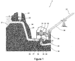
- Figure 1 depicts a layout of a hydroelectric power plant.
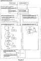
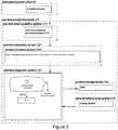
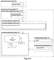
- Figure 2 , 3 and 4 depict a hydroelectric power plant real-time monitoring system, in accordance with the invention, in respectively a first, second and third embodiment.
- Figure 2 , 3 and 4 as a flowchart also depict respectively a first, a second and a third hydroelectric power plant real-time monitoring method, in accordance with the invention, in respectively a first, second and third embodiment.
- the first, second and third embodiments of the hydroelectric power plant real-time monitoring system and method, object of the invention are described below with reference to the layout of the hydroelectric power plant of Figure 1 .
- hydroelectric power plant real-time monitoring system and method, object of the invention are not limited to said hydroelectric power plant layout.
- Hydraulic, mechanic and/or electric components of said hydroelectric power plant layout can be modified or replaced by other hydraulic, mechanic and/or electric components.
- others hydraulic, mechanic and/or electric components can be added to said hydroelectric power plant layout, such as pumps, Francis turbines, Pelton turbines, Kaplan turbines, Bulb turbines, Propeller turbines, air vessels, surge tanks, pressurized surge tanks, tailrace water tunnel, by-pass discharge valve, motor-generators with fixed or variable speed machine and frequency converters.
- the hydroelectric power plant layout comprises hydraulic components, mechanic components and electric components.
- the hydraulic components comprise a reservoir 21, a surge tank 22, a gallery 23, a penstock 24, pipes 25, a valve 26, guide vanes 27, blades 28, a turbine and/or a pump 29 and a draft tube 38.
- the mechanic components comprise turbine inertias, motor-generator inertias, shaft stiffness and shaft damping.
- the electric components comprise a motor-generator 31 and related excitation system, a transformer 35, a circuit breakers and transmission lines 36.
- the hydroelectric power plant has foundations 34.
- the real-time monitoring system 1 comprises a real-time data acquisition system 11, a real-time simulation system 12 and a real-time diagnostic system 13.
- the real-time monitoring system 1 may comprise a preventive simulation system 16 and a preventive diagnostic system 17 as well as an archivage storage system 15 and a secured remote access system 14.
- the real-time data acquisition system 11 is connected to dedicated sensors positioned in a hydroelectric power plant and is configured to acquire in real-time real-time measured power plant data, said real-time measured power plant data comprising real-time measured simulation inputs 111 and at least one real-time measured monitored quantity 112.
- the real-time measured power plant data can be data related to a pressure signal, a water flow rate signal, a water level signal, a vibration signal, an acoustic signal, an acceleration signal, an induction signal, a torque signal, a rotational speed signal, a current signal, a voltage signal and/or a position signal.
- Such signals are captured with the help of dedicated sensors positioned on the desired power plant component. Said sensors are communicatively connected to the data acquisition system 11.
- the real-time measured simulation inputs 111 comprise power plant boundary conditions. Since the real-time simulation system 12 is configured to receive the real-time measured simulation inputs 111 from said real-time data acquisition system 11, the real-time simulation system 12 can be synchronized in real-time with the boundary conditions of the power plant 2. Therefore, the real-time simulation system 12 corresponds to a virtual model of the power plant 2.
- the real-time simulation system 12 can be considered as a clone, i.e. a duplication, of the power plant 2.
- the power plant boundary conditions can comprise at least one of the following boundary conditions parameters: a hydraulic boundary conditions parameter, such as a reservoir 21 water level, an electric boundary conditions parameters, such as a power network 37 voltage and/or a power network 37 frequency, or any combination thereof.
- the real-time measured simulation inputs 111 can comprise power plant control parameters.
- the power plant control parameters can comprise at least one of the following control parameters: a hydraulic control parameter, such as a guide vane 27 opening and/or a valve 26 opening and/or a blade 28 angle and/or a nozzle vane position, an electric control parameter, such as a motor-generator 31 excitation system voltage and/or a circuit breaker state, or any combination thereof.
- the real-time measured monitored quantity can comprise at least one of the following component quantities: a hydraulic component quantity, such as a penstock 24 pressure, a pipe (25) pressure and/or a surge tank 22 water level, a mechanic component quantity, such as a motor-generator rotor 32 rotational speed and/or a motor-generator rotor 32 torque, an electric component quantity, such as a motor-generator rotor 32 current and/or a motor-generator rotor 32 voltage, or any combination thereof.
- a hydraulic component quantity such as a penstock 24 pressure, a pipe (25) pressure and/or a surge tank 22 water level
- a mechanic component quantity such as a motor-generator rotor 32 rotational speed and/or a motor-generator rotor 32 torque
- an electric component quantity such as a motor-generator rotor 32 current and/or a motor-generator rotor 32 voltage, or any combination thereof.
- a real-time data acquisition system 11 configured to acquire in real-time real-time measured power plant data can be defined by the following.
- Physical quantities of the hydroelectric power plant 2 such as real-time measured power plant data comprising real-time measured simulation inputs and real-time measured monitored quantity, are converted with the help of an analog to digital conversion from an analog format to a digital format which is suitable for a computer to handle them. This conversion is done periodically with a given desired sampling frequency. The duration of the acquisition process of one sample should be smaller or equal to the sampling period.
- real-time measured simulation inputs 111 and real-time measured monitored quantity 112 are made available to the other components of the real-time monitoring system 1, in particular respectively to the real-time simulation system 12 and to the real-time diagnostic system 13, with a delay of at most one sampling period. Such a delay is considered acceptable since it is considered negligible in front of the fastness with which the monitoring system has to trigger an alarm.
- the sampling period have to respect at least the Nyquist-Shannon criterion. In practice however, the sampling period is at least 10 times smaller.
- the analog to digital conversion is configured so that the digital format is considered continuous by the other components of the real-time monitoring system 1, in particular by the real-time simulation system 12 and by the real-time diagnostic system 13. There is no special requirement on the absolute precision of the clock delivering the timing of the real-time acquisition system 11.
- the real-time data acquisition system 11 should not be interrupted by any other reason that powering on/off the entire real-time monitoring system 1.
- a real-time simulation software 121 is stored in a computer comprised in the real-time simulation system 12, the real-time simulation software 121 being configured to simulate in real-time a transient behavior of the power plant 2 based on the real-time measured simulation inputs 111.
- the simulation of the transient behavior of the power plant 2 can be provided by simultaneously modeling at least one hydraulic component, at least one mechanic component, at least one electric component of the hydroelectric power plant and at least one interaction between said components.
- the hydraulic component modeled in the simulation software 121 can comprise at least one of the following hydraulic elements: a reservoir 21, a pipe 25, a valve 26, a surge tank 22, a compensation opening, a turbine and/or a pump 29 or any combination thereof.
- the mechanic component modeled in the simulation software 121 can comprises at least one of the following mechanic elements: a turbine and/or a pump 29 inertia, a motor-generator 31 inertia, a shaft 30 stiffness, a shaft 31 damping or any combination thereof.
- the electric component modeled in the simulation software 121 can comprises at least one of the following electric elements: a motor-generator 31, a transformer 35, a circuit breaker, a transmission line 36 or any combination thereof.
- the real-time simulation system 12 is configured to provide in real-time real-time simulated power plant data related to said transient behavior of the power plant 2.
- the real-time simulated power plant data comprise at least one first real-time simulated monitored quantity 122.
- the first real-time simulated monitored quantity 122 corresponds to a simulated quantity of the real-time measured monitored quantity 112.
- the monitoring of the power plant is performed through the analysis of the first real-time simulated monitored quantity 122 and of the real-time measured monitored quantity 112.
- a real-time simulation system 12 can be defined by the following.
- the real-time simulation system 12 should be able to control the time point at which the real-time simulation monitored quantity 122 is delivered.
- the real-time simulation system 12 comprises a clocking system configured to deliver at a determined time the real-time simulation monitored quantity 122 once made available.
- the delivery of the real-time simulated monitored quantity 122 should occurs as soon as said quantity 122 has been provided by the real-time simulation system 12 so that the real-time simulation system 12 reproduce a virtual state of the hydroelectric power plant 2.
- the clocking system is also configured to launch the next simulation step at a determined time.
- the clocking system can be an internal clock, which means within the computer, or an external clock, in particular synchronous or asynchronous.
- the minimum time at which the real-time simulation monitored quantity 122 can be delivered is the computation time required to compute said quantity 122.
- the maximum time is the simulation time step.
- the real-time simulation monitored quantity 122 should be delivered with a frequency that permits other components of the real-time monitoring system 1, such as real-time diagnostic system 13, to use said quantity as relevant.
- the delivery of the real-time simulation monitored quantity 122 matches the simulation time step.
- the simulation time step should respect the Nyquist-Shannon criterion.
- the real-time simulation system 12 reproduces the real state of the hydroelectric power plant 2.
- a validation process of the real-time simulation software 121 is provided off-line and before implementing said software 121 in the real-time simulation system 12.
- the validation of the hydraulic part of the model consists in reproducing on-site measurements of an event producing significant amplitude to allow for validation.
- This event is usually an emergency shutdown performed from steady state conditions from 75% to 100% of nominal power of the plant. Then, time evolution of the penstock pressure, draft tube pressure, surge tank water level and unit overspeed are compared and related error margin is evaluated.
- the validation can be obtained from sudden no-load three phase short-circuit test performed on site or on a test platform. Then, comparison from field current and armature current enable to evaluate error margin for the electrical system.
- the real-time diagnostic system 13 is configured to analyze the monitored quantities, which can be a real-time measured monitored quantity 112 and a real-time simulated monitored quantity 122, and to trigger an alarm identifying a power plant transient behavior problem.
- the analysis of the monitored quantities can be achieved by comparing in real-time the quantities together and/or by computing in real-time outputs related to monitored quantities and comparing in real-time said outputs.
- the real-time diagnostic system 13 is configured to compare in real-time the real-time measured monitored quantity 112 with the first real-time simulated monitored quantity 122 to trigger, in case of deviation above a first predetermined threshold, a first alarm identifying a first power plant transient behavior problem.
- Such deviation may occur in case of unexpected event occurring on the actual power plant which would consequently not be reproduced by the real-time simulation system.
- unexpected events such as untimely guide-vane 27 closing, untimely valve closure, safety valve non-closure in case of emergency procedure, air-valve opening, pipe 25 air introduction, flow obstruction by foreign body or by wall roughness, cavitation inception, water hammer, water column separation, entrapped air, diaphragm cavitation, pipe 25 rupture or buckling, out of phase synchronization, motor-generator 32 short-circuit, pressure fluctuation due to active component, such as turbine and/or pump, pressure fluctuation due to passive component, such as vane 26, and/or any combination thereof.
- active component such as turbine and/or pump
- passive component such as vane 26, and/or any combination thereof.
- the real-time diagnostic system 13 can also be configured to compute in real-time at least one first output related to the real-time measured monitored quantity 112 and at least one second output related to the first real-time simulated monitored quantity 122 and compare in real-time said first output with said second output to trigger, in case of deviation above a second predetermined threshold, a first alarm identifying a first power plant transient behavior problem.
- the first output and the second output are respectively time-frequency analysis results of the real-time measured monitored quantity 112 and of the first real-time simulated monitored quantity 122.
- the first output and the second output are respectively envelope analysis results of the real-time measured monitored quantity 112 and of the first real-time simulated monitored quantity 122.
- the ouputs can be compared in terms of absolute values, relative values, RMS values, amplitudes spectra or phase values, time signal envelop shape and amplitude and/or peak-to-peak signal value.
- a real-time diagnostic system 13 configured to compare in real-time the above-mentioned quantities or outputs can be defined as follows.
- the real-time diagnostic system 13 reads quantities, in particular real-time simulated monitored quantity 122 and real-time measured monitored quantity 112, made available by respectively the real-time simulation system 12 and by the real-time data acquisition system 11, with a given sampling period.
- the real-time diagnostic system 13 is configured to compute in real-time outputs related to monitored quantities 122,112 and to compare in real-time said outputs. Said outputs may advantageously be dependent on previous results of the diagnostic system stored internally. Said outputs are compared in real-time to trigger, in case of deviation above a predetermined threshold, an alarm.
- the real-time diagnostic system 13 should run the diagnostic process periodically since the digital format of the monitored quantities 122,112 are considered continuous. The time required to process the diagnostic should be smaller or equal to the sampling period of the monitored quantities 122,112.
- the real-time monitoring system 1 can comprise a secured remote access system 14 configured to securely and remotely access and control the real-time diagnostic system 13.
- the secured remote access system 14 can be configured to control the real-time diagnostic system 13 by controlling the comparison of the real-time measured monitored quantity 112 and the first real-time simulated monitored quantity 122 or the computation and the comparison of the first and second outputs.
- the real-time monitoring system 1 can comprise an archival storage system 15 configured to store the real-time measured power plant data and the real-time simulated power plant data.
- the monitored quantity can be a hydraulic component quantity, such as a penstock 24 pressure, a pipe (25) pressure and/or a surge tank 22 water level, a mechanic component quantity, such as a motor-generator rotor 32 rotational speed and/or a motor-generator rotor (32) torque, an electric component quantity, such as a motor-generator rotor 32 current and/or a motor-generator rotor 32 voltage, or any combination thereof.
- a hydraulic component quantity such as a penstock 24 pressure, a pipe (25) pressure and/or a surge tank 22 water level
- a mechanic component quantity such as a motor-generator rotor 32 rotational speed and/or a motor-generator rotor (32) torque
- an electric component quantity such as a motor-generator rotor 32 current and/or a motor-generator rotor 32 voltage, or any combination thereof.
- the first power plant transient behavior problem can be chosen among untimely guide-vane 27 closing, untimely valve closure, safety valve non-closure in case of emergency procedure, air-valve opening, pipe 25 air introduction, flow obstruction by foreign body or by wall roughness, cavitation inception, water hammer, water column separation, entrapped air, diaphragm cavitation, pipe 25 rupture or buckling, out of phase synchronization, motor-generator 32 short-circuit, pressure fluctuation due to active component, such as turbine and/or pump, pressure fluctuation due to passive component, such as vane 26, and/or any combination thereof.
- active component such as turbine and/or pump
- passive component such as vane 26, and/or any combination thereof.
- a second alarm identifying a second power plant transient behavior problem can be triggered by the real-time diagnostic system 13.
- the real-time simulation system 12 is configured to provide real-time simulated power plant data comprising at least one second real-time simulated monitored quantity 123.
- the second real-time simulated monitored quantity 123 corresponds to a simulated quantity of a non-measured power plant quantity or of a non-measurable power plant quantity.
- the real-time diagnostic system 13 is here configured to compare in real-time the second real-time simulated monitored quantity 123 with a third predetermined threshold to trigger, when the second real-time simulated monitored quantity 123 exceeds the third predetermined threshold, a second alarm identifying a second power plant transient behavior problem.
- the real-time diagnostic system 13 can be configured to compute in real-time at least one third output related to the second real-time simulated monitored quantity 123 and compare in real-time the third output with a fourth predetermined threshold to trigger, when the third output exceeds the fourth predetermined threshold, a second alarm identifying a second power plant transient behavior problem.
- the third output can be time-frequency analysis result of the second real-time simulated monitored quantity 123.
- the third output can be envelope analysis result of the second real-time simulated monitored quantity 123.
- the secured remote access system 14 can be configured to control the real-time diagnostic system 13 by controlling the comparison of the second real-time simulated monitored quantity 123 and the third predetermined threshold or the computation of the third output and the comparison of the third output and the fourth predetermined threshold.
- the non-measured or the non-measurable power plant quantity can be any pressure along a gallery 23, a pipe 25 and/or along a penstock 24 and the second power plant transient behavior problem can be respectively an exceeding of a minimal or maximal predetermined pressure threshold along the gallery 23, the pipe 25 and/or along the penstock 24.
- the non-measured or the non-measurable power plant quantity can be a water flow rate in a pipe 25 and the second power plant transient behavior problem can be an exceeding of a maximal predetermined water flow rate threshold in the pipe 25.
- the non-measured or the non-measurable power plant quantity can be a current and/or voltage of a motor-generator 31 and/or of a transformer 35 and the second power plant transient behavior problem can be respectively an exceeding of a maximal predetermined current and/or voltage threshold of the motor-generator 31 and/or of the transformer 35.
- the non-measured or non-measurable power plant quantity can be a torque in a shaft 30 and the second power plant transient behavior problem can be an exceeding of a maximal predetermined torque threshold of the shaft 30.
- the non-measured or the non-measurable power plant quantity can be a torque transmitted in the foundations 34 of the power plant 2 and the second power plant transient behavior problem can be an exceeding of a maximal predetermined torque threshold transmitted in the foundations 34.
- a third alarm identifying a third power plant transient behavior problem can be triggered by the real-time diagnostic system 13.
- the real-time diagnostic system 13 is configured to compare in real-time the at least one real-time measured monitored quantity 112 with a fifth predetermined threshold to trigger, when the real-time measured monitored quantity 112 exceeds the fifth predetermined threshold, a third alarm identifying a third power plant transient behavior problem.
- the real-time diagnostic system can also be configured to compute in real-time at least one fourth output related to the real-time measured monitored quantity 112 and compare in real-time the fourth output with a sixth predetermined threshold to trigger, when the fourth output exceeds the sixth predetermined threshold, a third alarm identifying a third power plant transient behavior problem.
- the fourth output can be time-frequency analysis result of the real-time measured monitored quantity 112.
- the fourth output can be envelope analysis result of the real-time measured monitored quantity 112.
- the secured remote access system 13 can be configured to control the real-time diagnostic system 13 by controlling the comparison of the real-time measured monitored quantity 112 and the fifth predetermined threshold or the computation of the fourth output and the comparison of the fourth output and the sixth predetermined threshold.
- the real-time measured monitored quantity 112 can be a surge tank 22 water level and the third power plant transient behavior problem can be an exceeding of a minimal or maximal predetermined water level threshold in the surge tank 22.
- the real-time measured monitored quantity 112 can be a pressure at the bottom of a penstock 24 and the third power plant transient behavior problem is an exceeding of a minimal or maximal predetermined pressure threshold at the bottom of the penstock 24.
- the real-time measured monitored quantity can be a current and/or voltage of a motor-generator rotor 32 and/or stator 33 and the third power plant transient behavior problem can be respectively an exceeding of a maximal predetermined current and/or voltage threshold of said motor-generator rotor 32 and/or stator 33.
- the real-time monitoring system 1 may comprise a preventive simulation system 16 and a preventive diagnostic system 17.
- the preventive diagnostic system 17 is configured to trigger a fourth alarm identifying a fourth power plant transient behavior problem. Said fourth alarm ensures a preventive monitoring of a power plant which is subjected to undergo a change in a control parameter following a variation rate and therefore subjected to undergo a transient phenomenon.
- a power plant operator would be warned against a virtual power plant transient behavior problem which would occur when the power plant control parameter are changed from a real value to a virtual value following a variation rate, in particular when said change of control parameter is related to from a power plant operating sequence such as an emergency shutdown, a quick shutdown, an untimely valve closure or opening, a unit start-up, a unit loading and unit load rejection.
- the control parameter may correspond to turbine guide vane openings, valve openings, motor-generator excitation system voltage and circuit breaker state.
- the preventive simulation system 16 is configured to receive the real-time measured simulation inputs 111 from the real-time data acquisition system 11, the real-time measured simulation inputs 111 comprising a real value of at least one power plant control parameter.
- At least one predetermined virtual value of said power plant control parameter and at least one predetermined variation rate of said power plant control parameter are stored in a computer comprised in the preventive simulation system 16.
- the virtual value of power plant control parameter corresponds to a virtual state of the hydroelectric power plant. The objective is therefore to periodically check that, during operating condition of the power plant 2, a transient behavior of the power plant 2 from the real value to the virtual value of power plant control parameter following said variation rate would not jeopardize the safety of the power plant and of the surrounding natural, human and built environment.
- At least one preventive simulation software 161 is stored in the computer comprised in the preventive simulation system 16 and is configured to periodically simulate a virtual transient behavior of the power plant 2 from said real value to said virtual value of power plant control parameter following said predetermined variation rate of power plant control parameter.
- the simulation of the virtual transient behavior of the power plant 2 can be provided by simultaneously modeling at least one hydraulic component, at least one mechanic component, at least one electric component of the hydroelectric power plant and at least one interaction between said components.
- the hydraulic component modeled in the simulation software 161 can comprise at least one of the following hydraulic elements: a reservoir 21, a pipe 25, a valve 26, a surge tank 22, a compensation opening, a turbine and/or a pump 29 or any combination thereof.
- the mechanic component modeled in the simulation software 161 can comprises at least one of the following mechanic elements: a turbine and/or a pump 29 inertia, a motor-generator 31 inertia, a shaft 30 stiffness, a shaft 31 damping or any combination thereof.
- the electric component modeled in the simulation software 161 can comprises at least one of the following electric elements: a motor-generator 31, a transformer 35, a circuit breaker, a transmission line 36 or any combination thereof.
- the preventive simulation system 16 is configured to periodically provide preventive simulated power plant data related to the virtual transient behavior of the power plant 2 comprising at least one preventive simulated monitored quantity 162.
- the preventive simulation software 161 and the preventive simulation system 16 are respectfully configured to periodically simulate the above-mentioned virtual transient behavior and periodically provide said preventive simulated power plant data according to a predetermined preventive time step.
- This preventive time step can be chosen in a range between 30 seconds and 10 minutes, preferably chosen in a range between 30 seconds and 2 minutes and most preferably equal to 1 minute.
- the preventive simulation software 161 and the preventive simulation system 16 are respectfully configured to periodically simulate the above-mentioned virtual transient behavior and periodically provide said preventive simulated power plant data every time that the power plant 2 is changing of operating condition, which means when a power plant control parameter is modified.
- the preventive diagnostic system 17 is configured to compare the preventive simulated monitored quantity 162 with a seventh predetermined threshold to trigger, when the preventive simulated monitored quantity 162 exceeds the seventh predetermined threshold, a fourth alarm identifying a fourth power plant transient behavior problem in a preventive manner.
- the real-time diagnostic system 17 can be configured to compute at least one fifth output related to the preventive simulated monitored quantity 162 and compare the fifth output with a eighth predetermined threshold to trigger, when the fifth output exceeds the eighth predetermined threshold, a fourth alarm identifying a fourth power plant transient behavior problem in a preventive manner.
- the fifth output can be time-frequency analysis result of the preventive simulated monitored quantity 162.
- the fifth output can be envelope analysis result of the preventive simulated monitored quantity 162.
- the secured remote access system 14 can be configured to control the preventive diagnostic system 17 by controlling the comparison of the preventive simulated monitored quantity 162 and the seventh predetermined threshold or the computation of the fifth output and the comparison of the fifth output and the eighth predetermined threshold.
- the secured remote access system 14 can also be configured to control the predetermined preventive time step.
- the secured remote access system 14 can be configured to control the predetermined virtual value of the power plant control parameter and/or the predetermined variation rate of the power plant control parameter.
- the real-time measured simulation inputs 111 comprise a real value of each of a plurality of power plant control parameters.
- a predetermined virtual value of each of said plurality of power plant control parameters and a predetermined variation rate of each of said plurality of power plant control parameters are stored in the computer comprised in said preventive simulation system 16.
- a plurality of preventive simulation softwares 161 are stored in said computer and are configured to simulate periodically different virtual transient behaviors of the hydroelectric power plant 2, each preventive simulation software 161 simulating periodically a virtual transient behavior from a real value of one of said plurality of power plant control parameters to the corresponding predetermined virtual value of said power plant control parameter following the corresponding predetermined variation rate of said power plant control parameter.
- the preventive simulation softwares 161 are configured to provide periodically preventive simulated power plant data related to said virtual transient behavior comprising a preventive simulated monitored quantity 162.
- the preventive diagnostic system 17 can therefore be configured to compare each preventive simulated monitored quantity 162 with a corresponding predetermined threshold to trigger, when one of the preventive simulated monitored quantity 162 exceeds the corresponding predetermined threshold, said fourth alarm.
- the preventive diagnostic system 17 can be configured to compute an output related to each preventive simulated monitored quantity 162 and compare each output with a corresponding predetermined threshold to trigger, when one of the output exceeds the corresponding predetermined threshold, said fourth alarm.
- said plurality of preventive simulation software 161 can be configured to simulate simultaneously. With the help of the real-time monitoring system 1 described here above, a fourth alarm identifying different power plant transient behavior problems can be triggered.
- the change of power plant control parameter from a real value to a virtual value following a variation rate can be related to a power plant operating sequence such as an emergency shutdown, a quick shutdown, an untimely valve closure or opening, a unit start-up, a unit loading and unit load rejection.
- Said change of control parameter value can be related to a hydraulic control parameter value, such as a guide vane 27 opening and/or a valve 26 opening and/or a blade 28 angle and/or a nozzle vane position, to an electric control parameter value, such as a motor-generator 31 excitation system voltage and/or a circuit breaker state, or to any combination thereof.
- control devices are opened or closed in case of emergency shutdown, quick shutdown, or untimely closure or opening according to predetermined safety sequences which time evolution is ensured by mechanical devices such as safety diaphragms placed on the hydraulic command system of the servomotors and actuators of each control device.
- the closure or opening of the control devices will follow predetermined operating sequence with corresponding closing or opening rate.
- opening sequences of control devices such as circuit-breakers, are also predetermined.
- the preventive simulated monitored quantity 162 can advantageously be a surge tank 22 water level and the fourth power plant transient behavior problem can be an exceeding of a minimal or maximal predetermined water level threshold in the surge tank 22.
- the preventive simulated monitored quantity 162 can be any pressure along a gallery 23 and/or along a penstock 24 and the fourth power plant transient behavior problem can be respectively an exceeding of a minimal or maximal predetermined pressure threshold along the gallery 23 and/or along the penstock 24.
- the preventive simulated monitored quantity 162 can be a water flow rate in a pipe 25 and the fourth power plant transient behavior problem can be an exceeding of a maximal predetermined water flow rate threshold in the pipe 25.
- the preventive simulated monitored quantity 162 can be a current and/or voltage of a motor-generator 31 and/or of a transformer 35 and the fourth power plant transient behavior problem can be respectively an exceeding of a maximal predetermined current and/or voltage threshold of the motor-generator 31 and/or of the transformer 35.
- the preventive simulated monitored quantity 162 can be a turbine and/or pump 29 rotational speed and the fourth power plant transient behavior problem can be an exceeding of a maximal predetermined rotational speed of the turbine and/or pump 29.
- the simulation of the virtual transient behavior behaviors of the power plant can be manually adaptable based on past experiences.
- the predetermined virtual values and the predetermined variation rate of control parameter related to potential hazard can be continuously adapted to match as much as possible with real hazard potential.
- the system and method, object of the invention are part of a continuous learning process and may thus be considered as intelligent.
- Such learning process will be based on power plant event detection experience which will be built during industrial operation of the real-time monitoring system and method enabling to identify new sequences that can represent a risk for the power plant or its environment that should be included or excluded because of new countermeasures in the list of scenarios to be simulated with the virtual model.
- the monitoring system and method are configured to trigger said first alarm and advantageously said second alarm, said third alarm and/or said fourth alarm.
- particular embodiments of the invention can be configured to trigger an alarm chosen among said first alarm, said second alarm, said third alarm, said fourth alarm and/or any combination thereof. Said particular embodiments can be obtained depending of the wish to identify transient behavior problems related to said first, second, third and/or fourth alarms.
- the below mentioned second embodiment of the invention is configured to trigger said second alarm.
- the below mentioned third embodiment of the invention is configured to trigger said fourth alarm.
- the real-time data acquisition system 11' is connected to dedicated sensors positioned in a hydroelectric power plant 2 and is configured to acquire in real-time real-time measured power plant data, said real-time measured power plant data comprising real-time measured simulation inputs 111'.
- it is not necessary to acquire from the power plant real-time measured monitored quantity. Indeed, the second embodiment ensures an effective monitoring of a power plant in which measurement of monitored quantity is complex or impossible.
- the real-time monitoring system 1' comprises a real-time simulation system 12' configured to provide real-time simulated power plant data, the inputs of the real-time simulation system 12' comprising the real-time power plant measured simulation inputs 111'.
- the real-time simulation system 12' comprises a real-time simulation software 121' configured to simulate in real-time with the help of a computer the transient behavior of the power plant 2.
- the simulation of the transient behavior of the power plant 2 can be provided by simultaneously modeling at least one hydraulic component, at least one mechanic component and at least one electric component of the hydroelectric power plant as well as at least one interaction between said components.
- the hydraulic component modeled in the simulation software 121' can comprise at least one of the following hydraulic elements: a reservoir 21, a pipe 25, a valve 26, a surge tank 22, a compensation opening, a turbine and/or a pump 29 or any combination thereof.
- the mechanic component modeled in the simulation software 121' can comprises at least one of the following mechanic elements: a turbine and/or a pump 29 inertia, a motor-generator 31 inertia, a shaft 30 stiffness, a shaft 31 damping or any combination thereof.
- the electric component modeled in the simulation software 121' can comprises at least one of the following electric elements: a motor-generator 31, a transformer 35, a circuit breaker, a transmission line 36 or any combination thereof.
- the real-time simulated power plant data comprise at least one real-time simulated monitored quantity 123' corresponding to a simulated quantity of a non-measured power plant quantity or of a non-measurable power plant quantity.
- the delivery of the real-time simulated monitored quantity 123' should occurs as soon as said quantity 123' has been provided by the real-time simulation system 12' so that the real-time simulation system 12' reproduce a virtual state of the hydroelectric power plant 2.
- the real-time simulation system 12' one refers to the description of the real-time simulation system 12 of the first embodiment of the invention, Figure 2 .
- the real-time monitoring system 1' comprises a real-time diagnostic system 13' configured to compare in real-time the real-time simulated monitored quantity 123' with a predetermined threshold to trigger, when said real-time simulated monitored quantity exceeds said predetermined threshold, an alarm identifying a power plant transient behavior problem.
- the real-time diagnostic system 13' can be configured to compute in real-time at least one sixth output related to the real-time simulated monitored quantity 123' and compare in real-time the sixth output with a predetermined threshold to trigger, when said sixth output exceeds said predetermined threshold, an alarm identifying a power plant transient behavior problem.
- said power plant transient behavior problem can be the above-mentioned power plant transient behavior problem identified by the second alarm of the first embodiment.
- the diagnostic process computation duration should be smaller than the simulation time step of the real-time simulated monitored quantity 123'.
- the diagnostic process computation duration should be smaller than the simulation time step of the real-time simulated monitored quantity 123'.
- FIG. 3 depicts a hydroelectric power plant real-time monitoring method comprising the following steps:
- the real-time data acquisition system 11" is configured to acquire in real-time from the power plant 2 real-time measured power plant data comprising real-time measured simulation inputs 111" comprising a real value of each of at least one power plant control parameter.
- it is not necessary to acquire form the power plant real-time measured monitored quantity.
- the third embodiment ensures a preventive monitoring of a power plant which is subjected to undergo a change in a control parameter following a variation rate and therefore subjected to undergo a transient phenomenon.
- the control parameter may correspond to turbine guide vane openings, valve openings, motor-generator excitation system voltage and circuit breaker state.
- the real-time monitoring system 1" comprises a preventive simulation system 16" and a preventive diagnostic system 17".
- the preventive diagnostic system 17" is configured to trigger an alarm identifying a power plant transient behavior problem. With the help of said alarm, a power plant operator would be warned against a virtual power plant transient behavior problem which would occur when the power plant control parameter are changed from a real value to a virtual value following a variation rate, in particular when said change of control parameters is related to a power plant operating sequence such as an emergency shutdown, a quick shutdown, an untimely valve closure or opening, a unit start-up, a unit loading and unit load rejection.
- a power plant operating sequence such as an emergency shutdown, a quick shutdown, an untimely valve closure or opening, a unit start-up, a unit loading and unit load rejection.
- FIG. 4 depicts a hydroelectric power plant real-time monitoring method comprising the following steps:
- the above-mentioned real-time simulation software 121,121" and preventive simulation software 161,161" are configured to simulate with the help of a computer the transient behavior of the power plant 2.
- the simulation of the transient behavior of the power plant 2 can be provided by simultaneously modeling at least one hydraulic component, at least one mechanic component, at least one electric component of the hydroelectric power plant and at least one interaction between said components.
- the modeled hydraulic component can comprise at least one of the following hydraulic elements: a reservoir 21, a pipe 25, a valve 26, a surge tank 22, a compensation opening, a turbine and/or a pump 29 or any combination thereof.
- the modeled mechanic component can comprises at least one of the following mechanic elements: a turbine and/or a pump 29 inertia, a motor-generator 31 inertia, a shaft 30 stiffness, a shaft 31 damping or any combination thereof.
- the modeled electric component can comprises at least one of the following electric elements: a motor-generator 31, a transformer 35, a circuit breaker, a transmission line 36 or any combination thereof. Said components are modeled with ordinary differential equations (ODE) that all together form the state space equations, see equation (equ.1). This set can be solved for time by numerical solver, with the help of a computer.
- ODE ordinary differential equations
- the precision/complexity of the models can be varied with simulation/solver time step and also with the number of ODE describing the physics. Non-linearities are also taken into account, since the coefficient of the ODE do not have to be constant and can be a function of the state variables and/or time.
- the global set of equation (equ.1) modeling the entire hydroelectric power plant 2 includes ODE for:
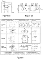
- the system (equ.2) is solved using the Finite Difference Method with a 1 st order centered scheme discretization in space and a scheme of Lax for the discharge variable.
- This approach leads to a system of ordinary differential equations that can be represented as a T-shaped equivalent scheme, as presented in Figure 5b .
- the hydraulic resistance R, the hydraulic inductance L, and the hydraulic capacitance C correspond respectively to energy losses, inertia and storage effects.
- N 11 N ⁇ D ref H
- Q 11 Q H ⁇ D ref 2
- T 11 T H ⁇ D ref 3
- the polar Suter representation of the 4 quadrants characteristic is used to handle properly 4 quadrants operation without numerical trouble.
- the Suter representation leads to WH and WB head and torque coefficients.
- H H(WH((y,Q,N))
- T T(WB((y,Q,N)).
- J is the rotating inertia
- w is the angular pulsation
- T are all the torques applying on the considered inertia.
- Equation equ.6 is setup for every rotating inertia of the rotating train including motor-generator and hydraulic machine rotating masses and the coupling parameters such as torsional stiffness, torsional damping, all rotating masses inertias, as well as electrical and hydraulic machines torques.
- the electromechanical part of the power plant consists in at least one electrical machine (motor-generator) 30,31,32,33, one transformer 35, one grid connection 36,37.
- the models of those components that are used in the cloning system are complex enough to represent all operating points, even those that are out of the nominal range of the components (short circuit conditions, asymmetry). They are also robust and well describe the transient behavior of the components when going from a stable operating point to another, due to a change of set point or to a default somewhere in the system.
- the ODE systems of the transformer 35 and the electrical machine 30,31,32,33 to show that they are detailed models.
- the three phase transformer model is based on the equivalent per phase electrical circuit, referred to primary side, as shown in Figure 8 :
- u 1 R 1 i 1 + L s 1 di 1 dt + L h 1 di 0 dt
- u 2 ′ R 2 ′ i 2 ′ + L s 2 ′ di 2 ′ dt + L h 2 di 0 dt
- the electrical machine model is based on the equivalent direct and quadrature (d and q) axis circuits of a laminated rotor machine. It takes into account the transient and sub-transient characteristic quantities, as shown in Figure 9 .
- This model of the synchronous machine is said to be based on dq axis.
- the electromagnetic circuits of the rotor are indeed well described and modeled when state variables are expressed in a two axis frame, which rotates in a synchronous manner with the rotor. Because then it is needed to express those variables with respect to the stator three phase system, there exist transformation to go from the rotating frame to the static frame, more suitable to express/describe from the stator side.
- This transformation is known as "Park” transform, which is mainly a projection of the d/q axis to a static three phase system, with a parameter which is the electrical angular position of the rotor.
Landscapes
- Engineering & Computer Science (AREA)
- Physics & Mathematics (AREA)
- General Physics & Mathematics (AREA)
- Automation & Control Theory (AREA)
- Chemical & Material Sciences (AREA)
- Combustion & Propulsion (AREA)
- Mechanical Engineering (AREA)
- General Engineering & Computer Science (AREA)
- Testing And Monitoring For Control Systems (AREA)
- Testing Of Devices, Machine Parts, Or Other Structures Thereof (AREA)
- Supply And Distribution Of Alternating Current (AREA)
Priority Applications (4)
| Application Number | Priority Date | Filing Date | Title |
|---|---|---|---|
| ES17193081T ES2843776T3 (es) | 2013-05-07 | 2013-05-07 | Sistema y método de monitorización en tiempo real de una central hidroeléctrica |
| EP17193081.1A EP3285128B1 (de) | 2013-05-07 | 2013-05-07 | Wasserkraftwerk-echtzeitüberwachungssystem und verfahren |
| PT171930811T PT3285128T (pt) | 2013-05-07 | 2013-05-07 | Sistema e método de monitorização em tempo real de central hidroelétrica |
| SI201331837T SI3285128T1 (sl) | 2013-05-07 | 2013-05-07 | Sistem in postopek za nadzor hidroelektrarne v realnem času |
Applications Claiming Priority (2)
| Application Number | Priority Date | Filing Date | Title |
|---|---|---|---|
| EP17193081.1A EP3285128B1 (de) | 2013-05-07 | 2013-05-07 | Wasserkraftwerk-echtzeitüberwachungssystem und verfahren |
| EP13166919.4A EP2801879B1 (de) | 2013-05-07 | 2013-05-07 | Wasserkraftwerk-Echtzeitüberwachungssystem und Verfahren |
Related Parent Applications (1)
| Application Number | Title | Priority Date | Filing Date |
|---|---|---|---|
| EP13166919.4A Division EP2801879B1 (de) | 2013-05-07 | 2013-05-07 | Wasserkraftwerk-Echtzeitüberwachungssystem und Verfahren |
Publications (2)
| Publication Number | Publication Date |
|---|---|
| EP3285128A1 true EP3285128A1 (de) | 2018-02-21 |
| EP3285128B1 EP3285128B1 (de) | 2020-11-18 |
Family
ID=48444067
Family Applications (2)
| Application Number | Title | Priority Date | Filing Date |
|---|---|---|---|
| EP17193081.1A Active EP3285128B1 (de) | 2013-05-07 | 2013-05-07 | Wasserkraftwerk-echtzeitüberwachungssystem und verfahren |
| EP13166919.4A Active EP2801879B1 (de) | 2013-05-07 | 2013-05-07 | Wasserkraftwerk-Echtzeitüberwachungssystem und Verfahren |
Family Applications After (1)
| Application Number | Title | Priority Date | Filing Date |
|---|---|---|---|
| EP13166919.4A Active EP2801879B1 (de) | 2013-05-07 | 2013-05-07 | Wasserkraftwerk-Echtzeitüberwachungssystem und Verfahren |
Country Status (5)
| Country | Link |
|---|---|
| EP (2) | EP3285128B1 (de) |
| ES (2) | ES2843776T3 (de) |
| NO (1) | NO2801879T3 (de) |
| PT (2) | PT3285128T (de) |
| SI (2) | SI3285128T1 (de) |
Cited By (2)
| Publication number | Priority date | Publication date | Assignee | Title |
|---|---|---|---|---|
| KR20220155832A (ko) * | 2021-05-17 | 2022-11-24 | 한국전력공사 | 감시 센서를 통한 동기 조상기 또는 발전기의 엔드 영역 문제 경감 시스템 및 방법 |
| RU2831741C1 (ru) * | 2023-12-14 | 2024-12-12 | Федеральное государственное бюджетное учреждение науки Институт теплофизики им. С.С. Кутателадзе Сибирского отделения Российской академии наук | Способ подавления пульсаций давления в гидротурбине |
Families Citing this family (30)
| Publication number | Priority date | Publication date | Assignee | Title |
|---|---|---|---|---|
| US10042964B2 (en) | 2015-03-02 | 2018-08-07 | General Electric Company | Method of evaluating a part |
| CN104808654B (zh) * | 2015-04-28 | 2017-06-16 | 重庆华数机器人有限公司 | 一种用于伺服驱动器频率响应的测试系统及方法 |
| CN105278345A (zh) * | 2015-10-13 | 2016-01-27 | 广州电力机车有限公司 | 基于异步发电机无功补偿技术的hil和rcp准实时仿真系统 |
| US10099804B2 (en) | 2016-06-16 | 2018-10-16 | General Electric Company | Environmental impact assessment system |
| CN106368828B (zh) * | 2016-10-25 | 2023-02-24 | 中国神华能源股份有限公司 | 发电机组操作风险预判装置及预判方法 |
| CN106842989A (zh) * | 2017-03-30 | 2017-06-13 | 南方电网科学研究院有限责任公司 | 机电暂态实时仿真系统和方法 |
| US10234855B2 (en) * | 2017-04-17 | 2019-03-19 | Honeywell International Inc. | Apparatus and method for rationalizing and resolving alarms in industrial process control and automation systems |
| CN107633661B (zh) * | 2017-08-28 | 2019-06-25 | 国家电网公司 | 抽水蓄能机组振摆报警方法及装置 |
| CN109557827B (zh) * | 2017-09-25 | 2021-10-01 | 中国电力科学研究院 | 一种电网逻辑控制脚本的生成与结果仿真方法及系统 |
| CN108681262A (zh) * | 2018-05-14 | 2018-10-19 | 南方电网科学研究院有限责任公司 | 一种电网的全数字实时仿真系统、仿真方法及接口设备 |
| CN109346268A (zh) * | 2018-11-07 | 2019-02-15 | 山东泰开变压器有限公司 | 一种安装于水电站尾水平台的高电压大容量抗振型变压器及设计方法 |
| CN110147086A (zh) * | 2019-04-29 | 2019-08-20 | 上海外高桥第二发电有限责任公司 | 电厂中在线设备的健康状态的确定方法及系统 |
| CN112502883B (zh) * | 2019-09-16 | 2023-07-14 | 国电南瑞南京控制系统有限公司 | 考虑频率稳定特性的水轮机调速器参数整定方法及装置 |
| CN111365186B (zh) * | 2020-04-24 | 2025-03-21 | 中国电建集团成都勘测设计研究院有限公司 | 一种水电站调压井水位信号测量及传输系统 |
| US11201779B1 (en) | 2020-09-11 | 2021-12-14 | Cerner Innovation, Inc. | Generation of synthetic alerts and unified dashboard for viewing multiple layers of data center simultaneously |
| CN112398219A (zh) * | 2020-10-21 | 2021-02-23 | 中国神华能源股份有限公司国华电力分公司 | 电厂智能监盘方法、系统及电子设备 |
| CN112502894B (zh) * | 2020-10-30 | 2022-08-26 | 南京南瑞水利水电科技有限公司 | 一种监测发电机组效率的水轮机调速器控制方法和装置 |
| CN112360673A (zh) * | 2020-12-08 | 2021-02-12 | 中国长江电力股份有限公司 | 水轮机调速器导叶开度监测装置及方法 |
| CN112906180B (zh) * | 2020-12-17 | 2024-03-29 | 中国人民解放军63919部队 | 一种电性能仿真设备 |
| CN112664379A (zh) * | 2020-12-22 | 2021-04-16 | 国家电网有限公司 | 水轮机组故障预判方法及装置 |
| CN114687907A (zh) * | 2020-12-29 | 2022-07-01 | 中国电建集团华东勘测设计研究院有限公司 | 水电站输水发电系统水力安全预警方法 |
| WO2022149073A1 (en) * | 2021-01-05 | 2022-07-14 | Mohammad Durali | Governor realtime/hardware in the loop testing and hydropower plant operator training |
| CN113898516A (zh) * | 2021-11-09 | 2022-01-07 | 国网信通亿力科技有限责任公司 | 一种小水电运营样本生产数据现场采样收集方法 |
| CN114060200B (zh) * | 2021-11-18 | 2022-09-30 | 中国水利水电科学研究院 | 一种同时测量工作闸门和活动导叶漏水量的方法 |
| CN115573845B (zh) * | 2022-09-14 | 2023-07-25 | 华电电力科学研究院有限公司 | 一种融合机组在离线数据的振摆趋势预警方法和系统 |
| CN116519281B (zh) * | 2023-04-28 | 2024-06-11 | 华能澜沧江水电股份有限公司 | 一种基于工业互联网的受油器浮动瓦磨损诊断系统及方法 |
| CN118050173B (zh) * | 2024-04-16 | 2024-06-18 | 三峡金沙江川云水电开发有限公司 | 一种水电机组调速系统低油压试验方法及系统 |
| KR102903662B1 (ko) * | 2024-06-20 | 2025-12-22 | 한국수력원자력 주식회사 | 양수 발전 설비의 상태 진단 방법 |
| CN118567285B (zh) * | 2024-07-31 | 2024-11-19 | 中国电建集团贵阳勘测设计研究院有限公司 | 一种砂石生产废水处理系统控制模型生成方法 |
| CN120805282B (zh) * | 2025-09-17 | 2026-01-30 | 中国电建集团西北勘测设计研究院有限公司 | 一种水电站尾水系统尾导结合段衔接结构的建模方法 |
Citations (3)
| Publication number | Priority date | Publication date | Assignee | Title |
|---|---|---|---|---|
| KR20010056616A (ko) * | 1999-12-16 | 2001-07-04 | 임정규 | 수차발전기 및 펌프모터의 실시간 효율감시시스템 |
| US20120072029A1 (en) * | 2010-09-20 | 2012-03-22 | Heatvu Inc. | Intelligent system and method for detecting and diagnosing faults in heating, ventilating and air conditioning (hvac) equipment |
| EP2525087A2 (de) * | 2011-05-19 | 2012-11-21 | General Electric Company | Zustandsüberwachung von Windturbinen |
-
2013
- 2013-05-07 NO NO13166919A patent/NO2801879T3/no unknown
- 2013-05-07 ES ES17193081T patent/ES2843776T3/es active Active
- 2013-05-07 EP EP17193081.1A patent/EP3285128B1/de active Active
- 2013-05-07 SI SI201331837T patent/SI3285128T1/sl unknown
- 2013-05-07 PT PT171930811T patent/PT3285128T/pt unknown
- 2013-05-07 EP EP13166919.4A patent/EP2801879B1/de active Active
- 2013-05-07 ES ES13166919.4T patent/ES2648988T3/es active Active
- 2013-05-07 SI SI201330844T patent/SI2801879T1/en unknown
- 2013-05-07 PT PT131669194T patent/PT2801879T/pt unknown
Patent Citations (3)
| Publication number | Priority date | Publication date | Assignee | Title |
|---|---|---|---|---|
| KR20010056616A (ko) * | 1999-12-16 | 2001-07-04 | 임정규 | 수차발전기 및 펌프모터의 실시간 효율감시시스템 |
| US20120072029A1 (en) * | 2010-09-20 | 2012-03-22 | Heatvu Inc. | Intelligent system and method for detecting and diagnosing faults in heating, ventilating and air conditioning (hvac) equipment |
| EP2525087A2 (de) * | 2011-05-19 | 2012-11-21 | General Electric Company | Zustandsüberwachung von Windturbinen |
Cited By (2)
| Publication number | Priority date | Publication date | Assignee | Title |
|---|---|---|---|---|
| KR20220155832A (ko) * | 2021-05-17 | 2022-11-24 | 한국전력공사 | 감시 센서를 통한 동기 조상기 또는 발전기의 엔드 영역 문제 경감 시스템 및 방법 |
| RU2831741C1 (ru) * | 2023-12-14 | 2024-12-12 | Федеральное государственное бюджетное учреждение науки Институт теплофизики им. С.С. Кутателадзе Сибирского отделения Российской академии наук | Способ подавления пульсаций давления в гидротурбине |
Also Published As
| Publication number | Publication date |
|---|---|
| SI3285128T1 (sl) | 2021-05-31 |
| PT2801879T (pt) | 2017-11-29 |
| SI2801879T1 (en) | 2018-03-30 |
| ES2648988T3 (es) | 2018-01-09 |
| EP2801879A1 (de) | 2014-11-12 |
| PT3285128T (pt) | 2021-01-19 |
| EP3285128B1 (de) | 2020-11-18 |
| EP2801879B1 (de) | 2017-09-27 |
| ES2843776T3 (es) | 2021-07-20 |
| NO2801879T3 (de) | 2018-02-24 |
Similar Documents
| Publication | Publication Date | Title |
|---|---|---|
| EP2801879B1 (de) | Wasserkraftwerk-Echtzeitüberwachungssystem und Verfahren | |
| US7231282B2 (en) | Device and method for a functional test of one wind turbine generator plant | |
| Naghizadeh et al. | Modeling hydro power plants and tuning hydro governors as an educational guideline | |
| CN113675878B (zh) | 海上风电场并网性能测试方法、系统、计算机设备和介质 | |
| So et al. | Out-of-step detection algorithm using frequency deviation of voltage | |
| KR102230468B1 (ko) | 계통 동요 데이터를 이용한 전력 설비 모델의 검증 장치 및 그 방법 | |
| Anagnostou et al. | Impact of overexcitation limiters on the power system stability margin under stressed conditions | |
| Seman et al. | Low voltage ride-through analysis of 2 MW DFIG wind turbine-grid code compliance validations | |
| Simani et al. | Fault diagnosis of a wind turbine simulated model via neural networks | |
| Zaid et al. | Wind turbine fault detection based on nonlinear observer | |
| Murat et al. | Validation of hydroelectric power plant model for speed governor development studies | |
| Johnson et al. | Pelton turbine needle control model development, validation, and governor designs | |
| You et al. | An intelligent adaptive load shedding scheme | |
| Undrill et al. | Turbine-generator impact torques in routine and fault operations | |
| Curran et al. | WTG grid compliance testing and validation part 1: grid-converter test rig measurement and verification based on the IEC 61400-21-4 | |
| Rafikov et al. | Development of a Tool for Automated Verification of a Synchronous Generator Models Together with Turbine and Excitation System Using PMU Technology | |
| Nabil et al. | Constrained Kalman filter based detection and isolation of sensor faults in a wind turbine | |
| Hwas et al. | Nonlinear observer-based fault detection and isolation for wind turbines | |
| Nicolet et al. | Simulation of transient phenomena in Francis turbine power plants: Hydroelectric interaction | |
| Sørensen et al. | Progress in IEC 61400-27 | |
| Assenkamp | Modelling of synchronous generators for the analysis of frequency transients above 1 Hz/s | |
| Bondareva et al. | Comparison of the results of full-scale experiment and long term dynamics simulation in the Siberian Interconnected Power System | |
| Segerstrom et al. | Modeling Components of a Turbine-Generator System for Sub-Synchronous Oscillation Studies with Modelica | |
| Assenkamp et al. | Capability of synchronous machines to ride through events with high ROCOF | |
| Holst et al. | Dynamic model of hydro power plant “Djerdap I” in Serbia |
Legal Events
| Date | Code | Title | Description |
|---|---|---|---|
| PUAI | Public reference made under article 153(3) epc to a published international application that has entered the european phase |
Free format text: ORIGINAL CODE: 0009012 |
|
| STAA | Information on the status of an ep patent application or granted ep patent |
Free format text: STATUS: THE APPLICATION HAS BEEN PUBLISHED |
|
| AC | Divisional application: reference to earlier application |
Ref document number: 2801879 Country of ref document: EP Kind code of ref document: P |
|
| AK | Designated contracting states |
Kind code of ref document: A1 Designated state(s): AL AT BE BG CH CY CZ DE DK EE ES FI FR GB GR HR HU IE IS IT LI LT LU LV MC MK MT NL NO PL PT RO RS SE SI SK SM TR |
|
| STAA | Information on the status of an ep patent application or granted ep patent |
Free format text: STATUS: REQUEST FOR EXAMINATION WAS MADE |
|
| 17P | Request for examination filed |
Effective date: 20180503 |
|
| RBV | Designated contracting states (corrected) |
Designated state(s): AL AT BE BG CH CY CZ DE DK EE ES FI FR GB GR HR HU IE IS IT LI LT LU LV MC MK MT NL NO PL PT RO RS SE SI SK SM TR |
|
| GRAP | Despatch of communication of intention to grant a patent |
Free format text: ORIGINAL CODE: EPIDOSNIGR1 |
|
| STAA | Information on the status of an ep patent application or granted ep patent |
Free format text: STATUS: GRANT OF PATENT IS INTENDED |
|
| INTG | Intention to grant announced |
Effective date: 20200609 |
|
| GRAS | Grant fee paid |
Free format text: ORIGINAL CODE: EPIDOSNIGR3 |
|
| GRAA | (expected) grant |
Free format text: ORIGINAL CODE: 0009210 |
|
| STAA | Information on the status of an ep patent application or granted ep patent |
Free format text: STATUS: THE PATENT HAS BEEN GRANTED |
|
| AC | Divisional application: reference to earlier application |
Ref document number: 2801879 Country of ref document: EP Kind code of ref document: P |
|
| AK | Designated contracting states |
Kind code of ref document: B1 Designated state(s): AL AT BE BG CH CY CZ DE DK EE ES FI FR GB GR HR HU IE IS IT LI LT LU LV MC MK MT NL NO PL PT RO RS SE SI SK SM TR |
|
| REG | Reference to a national code |
Ref country code: GB Ref legal event code: FG4D |
|
| REG | Reference to a national code |
Ref country code: CH Ref legal event code: EP |
|
| REG | Reference to a national code |
Ref country code: IE Ref legal event code: FG4D |
|
| REG | Reference to a national code |
Ref country code: DE Ref legal event code: R096 Ref document number: 602013074222 Country of ref document: DE |
|
| REG | Reference to a national code |
Ref country code: AT Ref legal event code: REF Ref document number: 1336435 Country of ref document: AT Kind code of ref document: T Effective date: 20201215 |
|
| RAP2 | Party data changed (patent owner data changed or rights of a patent transferred) |
Owner name: POWER VISION ENGINEERING SARL |
|
| REG | Reference to a national code |
Ref country code: PT Ref legal event code: SC4A Ref document number: 3285128 Country of ref document: PT Date of ref document: 20210119 Kind code of ref document: T Free format text: AVAILABILITY OF NATIONAL TRANSLATION Effective date: 20210113 |
|
| REG | Reference to a national code |
Ref country code: SE Ref legal event code: TRGR |
|
| REG | Reference to a national code |
Ref country code: NO Ref legal event code: T2 Effective date: 20201118 |
|
| REG | Reference to a national code |
Ref country code: NL Ref legal event code: MP Effective date: 20201118 |
|
| PG25 | Lapsed in a contracting state [announced via postgrant information from national office to epo] |
Ref country code: RS Free format text: LAPSE BECAUSE OF FAILURE TO SUBMIT A TRANSLATION OF THE DESCRIPTION OR TO PAY THE FEE WITHIN THE PRESCRIBED TIME-LIMIT Effective date: 20201118 Ref country code: FI Free format text: LAPSE BECAUSE OF FAILURE TO SUBMIT A TRANSLATION OF THE DESCRIPTION OR TO PAY THE FEE WITHIN THE PRESCRIBED TIME-LIMIT Effective date: 20201118 Ref country code: GR Free format text: LAPSE BECAUSE OF FAILURE TO SUBMIT A TRANSLATION OF THE DESCRIPTION OR TO PAY THE FEE WITHIN THE PRESCRIBED TIME-LIMIT Effective date: 20210219 |
|
| REG | Reference to a national code |
Ref country code: DE Ref legal event code: R082 Ref document number: 602013074222 Country of ref document: DE Representative=s name: HAFT - KARAKATSANIS PATENTANWALTSKANZLEI, DE Ref country code: DE Ref legal event code: R081 Ref document number: 602013074222 Country of ref document: DE Owner name: POWER VISION ENGINEERING SARL, CH Free format text: FORMER OWNER: POWER VISION ENGINEERING SARL, ECUBLENS, CH |
|
| PG25 | Lapsed in a contracting state [announced via postgrant information from national office to epo] |
Ref country code: BG Free format text: LAPSE BECAUSE OF FAILURE TO SUBMIT A TRANSLATION OF THE DESCRIPTION OR TO PAY THE FEE WITHIN THE PRESCRIBED TIME-LIMIT Effective date: 20210218 Ref country code: IS Free format text: LAPSE BECAUSE OF FAILURE TO SUBMIT A TRANSLATION OF THE DESCRIPTION OR TO PAY THE FEE WITHIN THE PRESCRIBED TIME-LIMIT Effective date: 20210318 Ref country code: LV Free format text: LAPSE BECAUSE OF FAILURE TO SUBMIT A TRANSLATION OF THE DESCRIPTION OR TO PAY THE FEE WITHIN THE PRESCRIBED TIME-LIMIT Effective date: 20201118 Ref country code: PL Free format text: LAPSE BECAUSE OF FAILURE TO SUBMIT A TRANSLATION OF THE DESCRIPTION OR TO PAY THE FEE WITHIN THE PRESCRIBED TIME-LIMIT Effective date: 20201118 |
|
| REG | Reference to a national code |
Ref country code: LT Ref legal event code: MG9D |
|
| PG25 | Lapsed in a contracting state [announced via postgrant information from national office to epo] |
Ref country code: HR Free format text: LAPSE BECAUSE OF FAILURE TO SUBMIT A TRANSLATION OF THE DESCRIPTION OR TO PAY THE FEE WITHIN THE PRESCRIBED TIME-LIMIT Effective date: 20201118 |
|
| REG | Reference to a national code |
Ref country code: ES Ref legal event code: FG2A Ref document number: 2843776 Country of ref document: ES Kind code of ref document: T3 Effective date: 20210720 |
|
| PG25 | Lapsed in a contracting state [announced via postgrant information from national office to epo] |
Ref country code: RO Free format text: LAPSE BECAUSE OF FAILURE TO SUBMIT A TRANSLATION OF THE DESCRIPTION OR TO PAY THE FEE WITHIN THE PRESCRIBED TIME-LIMIT Effective date: 20201118 Ref country code: SK Free format text: LAPSE BECAUSE OF FAILURE TO SUBMIT A TRANSLATION OF THE DESCRIPTION OR TO PAY THE FEE WITHIN THE PRESCRIBED TIME-LIMIT Effective date: 20201118 Ref country code: CZ Free format text: LAPSE BECAUSE OF FAILURE TO SUBMIT A TRANSLATION OF THE DESCRIPTION OR TO PAY THE FEE WITHIN THE PRESCRIBED TIME-LIMIT Effective date: 20201118 Ref country code: EE Free format text: LAPSE BECAUSE OF FAILURE TO SUBMIT A TRANSLATION OF THE DESCRIPTION OR TO PAY THE FEE WITHIN THE PRESCRIBED TIME-LIMIT Effective date: 20201118 Ref country code: SM Free format text: LAPSE BECAUSE OF FAILURE TO SUBMIT A TRANSLATION OF THE DESCRIPTION OR TO PAY THE FEE WITHIN THE PRESCRIBED TIME-LIMIT Effective date: 20201118 Ref country code: LT Free format text: LAPSE BECAUSE OF FAILURE TO SUBMIT A TRANSLATION OF THE DESCRIPTION OR TO PAY THE FEE WITHIN THE PRESCRIBED TIME-LIMIT Effective date: 20201118 |
|
| REG | Reference to a national code |
Ref country code: DE Ref legal event code: R097 Ref document number: 602013074222 Country of ref document: DE |
|
| PG25 | Lapsed in a contracting state [announced via postgrant information from national office to epo] |
Ref country code: DK Free format text: LAPSE BECAUSE OF FAILURE TO SUBMIT A TRANSLATION OF THE DESCRIPTION OR TO PAY THE FEE WITHIN THE PRESCRIBED TIME-LIMIT Effective date: 20201118 |
|
| PLBE | No opposition filed within time limit |
Free format text: ORIGINAL CODE: 0009261 |
|
| STAA | Information on the status of an ep patent application or granted ep patent |
Free format text: STATUS: NO OPPOSITION FILED WITHIN TIME LIMIT |
|
| 26N | No opposition filed |
Effective date: 20210819 |
|
| PG25 | Lapsed in a contracting state [announced via postgrant information from national office to epo] |
Ref country code: NL Free format text: LAPSE BECAUSE OF FAILURE TO SUBMIT A TRANSLATION OF THE DESCRIPTION OR TO PAY THE FEE WITHIN THE PRESCRIBED TIME-LIMIT Effective date: 20201118 Ref country code: AL Free format text: LAPSE BECAUSE OF FAILURE TO SUBMIT A TRANSLATION OF THE DESCRIPTION OR TO PAY THE FEE WITHIN THE PRESCRIBED TIME-LIMIT Effective date: 20201118 |
|
| PG25 | Lapsed in a contracting state [announced via postgrant information from national office to epo] |
Ref country code: MC Free format text: LAPSE BECAUSE OF FAILURE TO SUBMIT A TRANSLATION OF THE DESCRIPTION OR TO PAY THE FEE WITHIN THE PRESCRIBED TIME-LIMIT Effective date: 20201118 Ref country code: LU Free format text: LAPSE BECAUSE OF NON-PAYMENT OF DUE FEES Effective date: 20210507 |
|
| REG | Reference to a national code |
Ref country code: BE Ref legal event code: MM Effective date: 20210531 |
|
| PG25 | Lapsed in a contracting state [announced via postgrant information from national office to epo] |
Ref country code: IE Free format text: LAPSE BECAUSE OF NON-PAYMENT OF DUE FEES Effective date: 20210507 |
|
| PG25 | Lapsed in a contracting state [announced via postgrant information from national office to epo] |
Ref country code: BE Free format text: LAPSE BECAUSE OF NON-PAYMENT OF DUE FEES Effective date: 20210531 |
|
| REG | Reference to a national code |
Ref country code: DE Ref legal event code: R082 Ref document number: 602013074222 Country of ref document: DE Representative=s name: KARAKATSANIS, GEORGIOS, DR., DE |
|
| PG25 | Lapsed in a contracting state [announced via postgrant information from national office to epo] |
Ref country code: HU Free format text: LAPSE BECAUSE OF FAILURE TO SUBMIT A TRANSLATION OF THE DESCRIPTION OR TO PAY THE FEE WITHIN THE PRESCRIBED TIME-LIMIT; INVALID AB INITIO Effective date: 20130507 |
|
| PG25 | Lapsed in a contracting state [announced via postgrant information from national office to epo] |
Ref country code: CY Free format text: LAPSE BECAUSE OF FAILURE TO SUBMIT A TRANSLATION OF THE DESCRIPTION OR TO PAY THE FEE WITHIN THE PRESCRIBED TIME-LIMIT Effective date: 20201118 |
|
| REG | Reference to a national code |
Ref country code: AT Ref legal event code: UEP Ref document number: 1336435 Country of ref document: AT Kind code of ref document: T Effective date: 20201118 |
|
| PG25 | Lapsed in a contracting state [announced via postgrant information from national office to epo] |
Ref country code: MK Free format text: LAPSE BECAUSE OF FAILURE TO SUBMIT A TRANSLATION OF THE DESCRIPTION OR TO PAY THE FEE WITHIN THE PRESCRIBED TIME-LIMIT Effective date: 20201118 |
|
| PG25 | Lapsed in a contracting state [announced via postgrant information from national office to epo] |
Ref country code: TR Free format text: LAPSE BECAUSE OF FAILURE TO SUBMIT A TRANSLATION OF THE DESCRIPTION OR TO PAY THE FEE WITHIN THE PRESCRIBED TIME-LIMIT Effective date: 20201118 |
|
| PG25 | Lapsed in a contracting state [announced via postgrant information from national office to epo] |
Ref country code: MT Free format text: LAPSE BECAUSE OF FAILURE TO SUBMIT A TRANSLATION OF THE DESCRIPTION OR TO PAY THE FEE WITHIN THE PRESCRIBED TIME-LIMIT Effective date: 20201118 |
|
| PGFP | Annual fee paid to national office [announced via postgrant information from national office to epo] |
Ref country code: DE Payment date: 20250521 Year of fee payment: 13 |
|
| PGFP | Annual fee paid to national office [announced via postgrant information from national office to epo] |
Ref country code: GB Payment date: 20250527 Year of fee payment: 13 Ref country code: ES Payment date: 20250627 Year of fee payment: 13 |
|
| PGFP | Annual fee paid to national office [announced via postgrant information from national office to epo] |
Ref country code: NO Payment date: 20250523 Year of fee payment: 13 |
|
| PGFP | Annual fee paid to national office [announced via postgrant information from national office to epo] |
Ref country code: IT Payment date: 20250527 Year of fee payment: 13 |
|
| PGFP | Annual fee paid to national office [announced via postgrant information from national office to epo] |
Ref country code: PT Payment date: 20250429 Year of fee payment: 13 |
|
| PGFP | Annual fee paid to national office [announced via postgrant information from national office to epo] |
Ref country code: FR Payment date: 20250528 Year of fee payment: 13 |
|
| PGFP | Annual fee paid to national office [announced via postgrant information from national office to epo] |
Ref country code: CH Payment date: 20250618 Year of fee payment: 13 |
|
| PGFP | Annual fee paid to national office [announced via postgrant information from national office to epo] |
Ref country code: AT Payment date: 20250522 Year of fee payment: 13 |
|
| PGFP | Annual fee paid to national office [announced via postgrant information from national office to epo] |
Ref country code: SI Payment date: 20250424 Year of fee payment: 13 Ref country code: SE Payment date: 20250521 Year of fee payment: 13 |