EP3285342B1 - Krypton-85-freie funkenstrecke mit einer entladungssonde - Google Patents
Krypton-85-freie funkenstrecke mit einer entladungssonde Download PDFInfo
- Publication number
- EP3285342B1 EP3285342B1 EP17185898.8A EP17185898A EP3285342B1 EP 3285342 B1 EP3285342 B1 EP 3285342B1 EP 17185898 A EP17185898 A EP 17185898A EP 3285342 B1 EP3285342 B1 EP 3285342B1
- Authority
- EP
- European Patent Office
- Prior art keywords
- electrode
- spark gap
- discharge probe
- light source
- gap device
- Prior art date
- Legal status (The legal status is an assumption and is not a legal conclusion. Google has not performed a legal analysis and makes no representation as to the accuracy of the status listed.)
- Active
Links
Images

Classifications
-
- F—MECHANICAL ENGINEERING; LIGHTING; HEATING; WEAPONS; BLASTING
- F02—COMBUSTION ENGINES; HOT-GAS OR COMBUSTION-PRODUCT ENGINE PLANTS
- F02C—GAS-TURBINE PLANTS; AIR INTAKES FOR JET-PROPULSION PLANTS; CONTROLLING FUEL SUPPLY IN AIR-BREATHING JET-PROPULSION PLANTS
- F02C7/00—Features, components parts, details or accessories, not provided for in, or of interest apart form groups F02C1/00 - F02C6/00; Air intakes for jet-propulsion plants
- F02C7/26—Starting; Ignition
- F02C7/264—Ignition
- F02C7/266—Electric
-
- H—ELECTRICITY
- H01—ELECTRIC ELEMENTS
- H01T—SPARK GAPS; OVERVOLTAGE ARRESTERS USING SPARK GAPS; SPARKING PLUGS; CORONA DEVICES; GENERATING IONS TO BE INTRODUCED INTO NON-ENCLOSED GASES
- H01T1/00—Details of spark gaps
- H01T1/20—Means for starting arc or facilitating ignition of spark gap
-
- F—MECHANICAL ENGINEERING; LIGHTING; HEATING; WEAPONS; BLASTING
- F02—COMBUSTION ENGINES; HOT-GAS OR COMBUSTION-PRODUCT ENGINE PLANTS
- F02P—IGNITION, OTHER THAN COMPRESSION IGNITION, FOR INTERNAL-COMBUSTION ENGINES; TESTING OF IGNITION TIMING IN COMPRESSION-IGNITION ENGINES
- F02P17/00—Testing of ignition installations, e.g. in combination with adjusting; Testing of ignition timing in compression-ignition engines
-
- F—MECHANICAL ENGINEERING; LIGHTING; HEATING; WEAPONS; BLASTING
- F23—COMBUSTION APPARATUS; COMBUSTION PROCESSES
- F23Q—IGNITION; EXTINGUISHING-DEVICES
- F23Q3/00—Igniters using electrically-produced sparks
-
- F—MECHANICAL ENGINEERING; LIGHTING; HEATING; WEAPONS; BLASTING
- F23—COMBUSTION APPARATUS; COMBUSTION PROCESSES
- F23R—GENERATING COMBUSTION PRODUCTS OF HIGH PRESSURE OR HIGH VELOCITY, e.g. GAS-TURBINE COMBUSTION CHAMBERS
- F23R3/00—Continuous combustion chambers using liquid or gaseous fuel
- F23R3/28—Continuous combustion chambers using liquid or gaseous fuel characterised by the fuel supply
- F23R3/36—Supply of different fuels
-
- G—PHYSICS
- G01—MEASURING; TESTING
- G01M—TESTING STATIC OR DYNAMIC BALANCE OF MACHINES OR STRUCTURES; TESTING OF STRUCTURES OR APPARATUS, NOT OTHERWISE PROVIDED FOR
- G01M3/00—Investigating fluid-tightness of structures
- G01M3/40—Investigating fluid-tightness of structures by using electric means, e.g. by observing electric discharges
-
- H—ELECTRICITY
- H01—ELECTRIC ELEMENTS
- H01T—SPARK GAPS; OVERVOLTAGE ARRESTERS USING SPARK GAPS; SPARKING PLUGS; CORONA DEVICES; GENERATING IONS TO BE INTRODUCED INTO NON-ENCLOSED GASES
- H01T2/00—Spark gaps comprising auxiliary triggering means
-
- H—ELECTRICITY
- H01—ELECTRIC ELEMENTS
- H01T—SPARK GAPS; OVERVOLTAGE ARRESTERS USING SPARK GAPS; SPARKING PLUGS; CORONA DEVICES; GENERATING IONS TO BE INTRODUCED INTO NON-ENCLOSED GASES
- H01T4/00—Overvoltage arresters using spark gaps
- H01T4/10—Overvoltage arresters using spark gaps having a single gap or a plurality of gaps in parallel
-
- H—ELECTRICITY
- H05—ELECTRIC TECHNIQUES NOT OTHERWISE PROVIDED FOR
- H05H—PLASMA TECHNIQUE; PRODUCTION OF ACCELERATED ELECTRICALLY-CHARGED PARTICLES OR OF NEUTRONS; PRODUCTION OR ACCELERATION OF NEUTRAL MOLECULAR OR ATOMIC BEAMS
- H05H1/00—Generating plasma; Handling plasma
- H05H1/24—Generating plasma
- H05H1/52—Generating plasma using exploding wires or spark gaps
-
- F—MECHANICAL ENGINEERING; LIGHTING; HEATING; WEAPONS; BLASTING
- F05—INDEXING SCHEMES RELATING TO ENGINES OR PUMPS IN VARIOUS SUBCLASSES OF CLASSES F01-F04
- F05D—INDEXING SCHEME FOR ASPECTS RELATING TO NON-POSITIVE-DISPLACEMENT MACHINES OR ENGINES, GAS-TURBINES OR JET-PROPULSION PLANTS
- F05D2260/00—Function
- F05D2260/99—Ignition, e.g. ignition by warming up of fuel or oxidizer in a resonant acoustic cavity
-
- F—MECHANICAL ENGINEERING; LIGHTING; HEATING; WEAPONS; BLASTING
- F23—COMBUSTION APPARATUS; COMBUSTION PROCESSES
- F23Q—IGNITION; EXTINGUISHING-DEVICES
- F23Q23/00—Testing of ignition installations
Definitions
- the subject matter disclosed herein relates to spark gaps for use in ignition systems or other suitable systems.
- Spark gaps are passive, two-terminal switches that are open when the voltage across the terminals is low, and then close when the voltage across the terminals exceeds a design value (e.g., 3 kV). The spark gap then re-opens when the current has fallen to a low level or when most of the energy from the voltage source is dissipated.
- the current is carried between two metal electrodes that are separated by a small 'gap' ( ⁇ mm) that is filled with a gas or gas mixture (e.g., Ar-H 2 -Kr) near atmospheric pressure.
- the gas is ordinarily insulating, but it becomes a conducting plasma 'spark' when the voltage between the two electrodes exceeds the design value which corresponds to the breakdown voltage.
- one parameter of interest may be the time between when a sufficient voltage is applied to the spark gap and the time at which it becomes conducting. This time corresponds to the 'breakdown' processes that initiate the transition of the gas from an insulator to a conductor.
- the time required for the second (avalanching) process is the 'formative time lag'. It is generally short and can be practically ignored. Thus, the time required for the first process (the initial electron) is the 'statistical time lag', and it is this 'first electron problem' that is of primary interest in practice.
- the 'first electron problem' is solved by doing nothing more than waiting for a cosmic ray to create a free electron when it collides with a gas atom, gas molecule, or surface within the device. Electron-ion pairs are always being created at a given rate in atmospheric air by energetic cosmic rays that can easily penetrate into gas volumes within devices and structures.
- a Geiger counter is an example of a device that detects such events.
- the ubiquitous cosmic-ray process cannot be relied upon to create effective free electrons within a required timeframe that may be needed for reliable operation of many devices that incorporate a spark gap.
- the timeframe is typically too short to rely on a cosmic ray based process because the interaction volume (the region between the electrodes) is relatively small.
- the conventional approach to solving the first-electron problem in a spark gap context is to add a source of radioactivity, for example in the form of radioactive krypton-85 (e.g., 85 Kr), which undergoes beta decay to emit an energetic (687 keV) electron, to generate seed electrons and reduce statistical time-lag to acceptable values.
- a source of radioactivity for example in the form of radioactive krypton-85 (e.g., 85 Kr), which undergoes beta decay to emit an energetic (687 keV) electron, to generate seed electrons and reduce statistical time-lag to acceptable values.
- Other radioactive materials such as tritium or thorium are sometimes used.
- the addition of a radioactive component is sometimes referred to as 'radioactive prompting' .
- radioactive materials even at trace level, are generally not desirable in a component or product because these materials add to the cost of manufacturing, handling, and shipping.
- FR 2 984 028 A1 relates to a spark-gap having a cathode whose surface is made of porous heat-resisting materials and discloses features generally corresponding to the preamble of claim 1.
- a spark gap device in one aspect as defined in claim 1, includes a first electrode having a first surface, a second electrode having a second surface offset from and facing the first surface, and a discharge probe configured to emit light toward the first and second surface such that photons emitted by the discharge probe when the spark gap device is operated are incident on the first surface and cause electron emission from the first surface, wherein the first electrode and the second electrode are disposed in a sealed envelope; the discharge probe is positioned exterior to the sealed envelope and is configured also to emit the light toward the second surface.
- a method for generating a conductive plasma includes applying a voltage across a spark gap device of claim 1 having a first electrode and a second electrode, where the first electrode includes a surface facing the second electrode, generating free electrons at the surface of the first electrode and the surface of the second electrode using a discharge probe as a light source, and subsequent to generating the free electrons, generating the conductive plasma across the spark gap device.
- the first electrode and the second electrode are disposed in a sealed envelope; and the discharge probe is positioned exterior to the sealed envelope.
- the method includes also generating free electrons at the surface of the second electrode using the discharge probe as a light source.
- the present approach relates to spark gaps, such as those used in ignition systems for combustion engines, as well as in other contexts such as surge protection, power switching, and so forth.
- FIG. 1 an illustrative example of the operation of a spark gap is illustrated in FIG. 1 .
- the voltage waveform 10 is a ramp
- the rate of voltage rise is 6 kV/s
- the desired voltage rating is 3 ⁇ 0.05 kV
- the total time from Point 12 (the time sufficient voltage for the spark gap to fire is reached) to Point 14 (the time when the spark gap is closed) should be no more than 17 ms. This time corresponds to the 'breakdown' processes that initiate the transition of the gas from an insulator to a conductor.
- the breakdown voltage 22 depends on the intrinsic properties of the spark-gap, as well as the voltage ramp 10 that is defined by other portions of the circuit. If the rate of voltage rise is slower, then the voltage-rise between Point 12 and Point 14 is reduced, so Point 12 is sometimes referred to as the 'intrinsic' breakdown voltage of the spark gap, because it does not depend on the circuit properties.
- an idealized but useful view of electrical breakdown is to view it as a two-step process, with a first component corresponding to a 'statistical' time 16 for the first electron to appear (at time 20), followed by a second component corresponding to a 'formative' time 18 for the electrons to 'avalanche' to a highly conductive state, occurring at time 22 when the spark gap closes.
- the difference between the voltage 30 sufficient for the spark gap to fire and the voltage 32 at which the spark gap closes is the variation 34 in gap voltage.
- a free electron appears at some time and location in the gas surrounding the spark gap, and is accelerated by the electric field that is created by the potential difference between the electrodes. Once it gains sufficient energy there is some probability for it to ionize a gas atom or molecule and release a second free electron. Each electron is then accelerated and the process repeats, leading to an electron avalanche that makes the gas highly conducting.
- the energy gain and multiplication processes must overcome various energy and particle loss processes, and first electrons are preferably created in certain locations (e.g., near the negative electrode or cathode) for maximum effectiveness.
- the time 16 required for the first process is referred to as the 'statistical time lag', and it is this 'first electron problem' that is addressed in the present approach.
- the present approach solves the first-electron problem in the spark gap (i.e., the statistical time lag) without relying on the traditional approach of providing a source of ionizing radiation (e.g., 85 Kr), which is generally undesirable, and thus does not employ 'radioactive prompting'.
- the present approach does not rely solely on the effects of cosmic-rays, for generation of the initial electrons as such rays typically are insufficient to generate first electrons at a sufficient rate needed in a spark gap ignition context (or other industrial or mechanical context).
- a light source e.g., a discharge probe that includes electrodes in a sealed tube filled with an inert gas
- a light source that emits at a specified or designed nominal wave length (or range of wavelengths) at a suitable or sufficient level of emitted flux.
- the absorption of a photon by a material causes the material to emit an electron.
- the energy of the photon must exceed the work-function of the material.
- the work-function of materials is typically in the range 2-6 electron-volts.
- the wavelength of light should, therefore, be shorter than a certain value in the range 200-600 nanometers, corresponding to 2-6 electron-volts, with the exact value depending on the specific material.
- the spectral transmission of the envelope should be considered.
- borosilicate glass absorbs strongly at wavelengths less than 300 nanometers, corresponding to an energy of 4 electron-volts. So if, by way of example, a given material has a work-function of 3 electron-volts, and a light source is placed outside the glass envelope to create photoelectrons, then only photons of energy 3-4 electron volts (300-400 nanometers) will be effective.
- Photons with wavelength longer than 400 nanometers will not have sufficient energy to cause photoemission, and photons with wavelength shorter than 300 nanometers will be absorbed by the glass.
- the material to be photo-electrically stimulated, the wavelength of light to be employed, and the transmissive properties of the envelope are all factors to be considered in the design and configuration or a spark gap system as discussed herein. It should be noted that in other embodiments, the light source may be positioned inside of the envelope.
- the light source e.g., a discharge probe having wire electrodes sealed in a tube with inert gas
- the electrodes e.g., the cathode and/or the anode
- the emitted photons incident on the surface of the electrode cause it to emit electrons via the photo-electric effect. These electrons are then available to initiate the gas discharge or breakdown event.
- the electrode on which photons from the light source are incident and which emits electrons is a conventional electrode (e.g., a conventional conductive metal substrate and surface), as opposed to an electrode having coated surface or other emissive coating (e.g., a special purpose emissive coating) and in contrast to a photoelectrode (e.g., a photocathode or other an annular electrode or coil having a coating or composition specifically for the purpose of emitting electrons in response to light photons).
- a photoelectrode e.g., a photocathode or other an annular electrode or coil having a coating or composition specifically for the purpose of emitting electrons in response to light photons.
- electrodes having a coated surface and/or photoelectrodes may be utilized.
- a light source may be used, which may be adjusted so as to find a suitable (or optimal) range of wavelengths and/or light flux for a given spark gap configuration or application.
- the light source may be a discharge probe that includes wire electrodes (e.g., two or more electrodes) sealed in an envelope filled with an inert gas (e.g., nitrogen, argon, or another suitable inert gas).
- the discharge probe may be operated at a minimum threshold current that will generate light sufficient to cause the spark gap to breakdown.
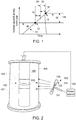
- FIG. 2 depicts an example of a spark gap 100 suitable for use in an ignition system (such as for use in combustion engines), surge protection contexts, or power switching.
- the spark gap 100 refers to an assembly of a separated pair of electrodes (i.e., anode 102, and cathode 104) within a sealed environment 105 (e.g., a glass envelope or housing) containing a gas mixture 106.
- a sealed environment 105 e.g., a glass envelope or housing
- a light source 120 may be employed.
- the light source 120 may be used to assess the effect of wavelength (photon energy) and photon flux on the breakdown voltage of different gaps, and to thereby identify suitable ranges of photon energy and/or flux for different gap types and/or distances.
- the light source 120 may be a discharge probe 121 that includes electrodes 122 (e.g., two or more wire electrodes) sealed in a tube 124 filled with an inert gas 126 (e.g., nitrogen).
- a pressure of the inert gas 126 in the tube 124 may be between 1 Torr and 10 Torr, between 2 Torr and 8 Torr, or between 4 Torr and 6 Torr. In other embodiments, the pressure of the inert gas 126 in the tube 124 may be approximately (e.g., within 5% or within 10% of) 5 Torr.
- the light source may also have the first electron problem.
- the light source 120 may be tuned and/or adjusted based on operating conditions of the spark gap 100 to reduce the first electron problem.
- the light source 120 may be larger than a gap between the first electrode 102 and the second electrode 104 (e.g., to intercept cosmic rays), the light source 120 may include pointy electrodes (e.g., to encourage field emission), or a gas utilized within the light source 120 may be modified (e.g., so long as a suitable photon wavelength is achieved).
- a direct current (DC) voltage may be supplied to the electrodes 122 from a power source 128.
- current e.g., approximately 1 milli-Amp
- a first electrode 122 of the discharge probe may be coupled to the power source 128 and a second electrode 122 of the discharge probe may be coupled to the first electrode 102, the second electrode 104, or both.
- the power source 128 of the light source 120 having the electrodes 122 may be the same as the power source for the electrodes 102 and 104 of the spark gap 100.
- an amount of DC voltage supplied to the electrodes 122 from the power source 128 may adjust a wavelength, frequency, and/or amount of energy of the light emitted by the light source.
- the power supply 128 may be configured to apply sufficient voltage to the light source 120 sufficiently before the spark 100 gap is triggered to allow time to initiate the light source 120.
- the power supply 128 may provide voltage to the light source 120 between 100 milliseconds (ms) and 200 ms before a desired time for the spark gap 100 to fire.
- the light source 120 may include various combinations of the inert gas 126, pressures of the inert gas 126, an amount of DC voltage supplied to the electrodes 122, and/or a configuration of the electrodes 122 to produce light having predetermined characteristics (e.g., wavelength, frequency, flux, etc.).
- the light source 120 may generate light having a wavelength of between 100 micrometers ( ⁇ m) and 1000 ⁇ m, between 200 ⁇ m and 800 ⁇ m, or between 300 ⁇ m and 500 ⁇ m.
- the wavelength of the light source 120 may be adjusted by a gas composition within the light source 120, and an intensity of the light source 120 may be adjusted by the power source 128.
- the light source 120 may be positioned inside the sealed environment 105 of the spark gap 100. In other embodiments, the light source 120 may be outside of the sealed environment 105 of the spark gap (e.g., as shown in FIG. 2 ). For example, the light source 120 may be mounted to an exterior surface of the sealed environment 105 such that the light source 120 directs light (e.g., photons) toward a surface 130 of at least one of the electrodes 102 and/or 104. When photons are emitted from the light source 120 and directed toward the surface 130 of at least one of the electrodes 102 and/or 104 of the spark gap 100, a breakdown event may be initiated in the spark gap 100 by the photo-electric effect.
- light e.g., photons
- Utilizing the light source 120 disclosed herein may enable the spark gap to operate over a wide range of temperatures because the spectrum and/or intensity of light emitted by the discharge probe is relatively insensitive to temperature fluctuations.
- the electrodes 122 of the discharge probe 121 may include a metallic material (e.g., copper, aluminum, tungsten, or another suitable metallic material), which may be configured to withstand relatively high temperatures. Additionally, an operating life of the light source 120 may be enhanced because the current within the discharge probe (e.g., in the tube 124) is relatively low.
- FIG. 3 is a graphical illustration that shows results in terms of breakdown voltage for the spark gap 100 having the light source 120 (e.g., the discharge probe having the electrodes 122 sealed in the tube 124 filled with the inert gas 126) when compared to a spark gap that does not include 85 Kr or the light source 120.
- the spark gaps 100 having the light source 120 (Runs 4-6) were compared to three spark gaps that did not include either the light source 120 or 85 Kr (Runs 1-3).
- Weibull probabilities of each spark gap are shown on a y-axis 140 and breakdown voltage is shown on an x-axis 142.
- Weibull probabilities may refer to a statistical distribution of a variation in breakdown voltage over a number of operations (e.g., 100 operations) of a given spark gap (e.g., Runs 1-6).
- the spark gaps 100 having the light source 120 (Runs 4-6) generally produced a tight distribution of breakdown voltage, and a tighter distribution of breakdown voltage when compared to the spark gaps that did not include the light source 120 (Runs 1-3).
- the present approach is not directed to the reduction of the breakdown voltage, which may be an issue in other contexts. Instead, the present approach is directed to providing a tight distribution of breakdown voltage, particularly in the absence of 85 Kr, not to reduce the breakdown voltage. With this in mind, the present approach relates to the use of a suitable ranges of energy and flux of the photons (as discussed in greater detail below) for application to spark gaps 100.
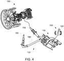
- FIG. 4 depicts an example of an engine 150, here a jet engine, in which the spark gap 100 using the light source 120 may be employed.
- the spark gap 100 may be included as part of the fuel ignition system 152 for the engine 150 by which a fuel stream or vapor is combusted.
- a spark gap 100 may be provided for one or more igniters 154.
- each spark gap 100 may be provided as part of an exciter component 156 in communication with a respective igniter 154 via a corresponding lead 160.
- spark events induced at a given spark gap 100 may correspond to a conductive flow between the electrodes of the spark gap 100, causing an ignition event at the corresponding igniter 154 and an ignition event during operation of the engine 150.
- an engine 150 such as that depicted in FIG. 4 is one possible use for a spark gap 100 as discussed herein (e.g., as part of an ignition system), a spark gap 100 as presently disclosed may also be used in other ignition and non-ignition contexts.
- inventions include an alternative approach to generating seed electrons at a spark gap, allowing 85 Kr to be eliminated from the gas mixture typically present at the spark gap while maintaining the same performance and function of the device.
- the present approach utilizes the photo-electric effect, using a light source with a specific nominal wave length (or range of wavelengths) at a specific level of emitted flux to generate seed electrons.
- the light source e.g., a discharge probe that includes electrodes in a sealed tube filled with inert gas
- the present approach may be retrofit in existing packaging, such that there would be no major changes in the manufacturing of the spark gap 100 or the remainder of the ignition system.
Landscapes
- Engineering & Computer Science (AREA)
- Chemical & Material Sciences (AREA)
- Combustion & Propulsion (AREA)
- Mechanical Engineering (AREA)
- General Engineering & Computer Science (AREA)
- Physics & Mathematics (AREA)
- Plasma & Fusion (AREA)
- Spectroscopy & Molecular Physics (AREA)
- General Physics & Mathematics (AREA)
- Investigating, Analyzing Materials By Fluorescence Or Luminescence (AREA)
- Plasma Technology (AREA)
- Ignition Installations For Internal Combustion Engines (AREA)
- Gas-Filled Discharge Tubes (AREA)
Claims (11)
- Funkenstreckenvorrichtung (100), umfassend:eine erste Elektrode (102) mit einer ersten Oberfläche (130);eine zweite Elektrode (104) mit einer zweiten Oberfläche, die von der ersten Oberfläche (130) versetzt und dieser zugewandt ist; undeine Entladungssonde (121), die dazu konfiguriert ist, Licht in Richtung der ersten Oberfläche (130) zu emittieren, sodass beim Betrieb der Funkenstreckenvorrichtung (100) von der Entladungssonde (121) emittierte Photonen auf die erste Oberfläche (130) auftreffen und bei der ersten Oberfläche (130) eine Elektronenemission verursachen;wobei die erste Elektrode (102) und die zweite Elektrode (104) in einer versiegelten Hülle (105) angeordnet sind, wobei die Entladungssonde (121) außerhalb der versiegelten Hülle (105) angeordnet ist, dadurch gekennzeichnet, dass:
die Entladungssonde (121) dazu konfiguriert ist, dass sie das Licht auch in Richtung der zweiten Oberfläche emittiert. - Funkenstreckenvorrichtung (100) nach Anspruch 1, wobei die Entladungssonde (121) eine dritte Elektrode (122) und eine vierte Elektrode (122) umfasst, die in einem mit einem Inertgas (126) gefüllten Rohr (124) eingeschlossen sind.
- Funkenstreckenvorrichtung (100) nach Anspruch 2, wobei die dritte Elektrode (122), die vierte Elektrode (122) oder beide eine Drahtelektrode umfassen und wobei es sich bei dem Inertgas (126) um Stickstoff handelt.
- Funkenstreckenvorrichtung (100) nach Anspruch 2 oder 3, wobei ein Druck des Inertgases (126) in dem Rohr (124) ungefähr 5 Torr beträgt.
- Funkenstreckenvorrichtung (100) nach einem der Ansprüche 2 bis 4, wobei die Entladungssonde (121) eine Stromquelle (128) umfasst, die dazu konfiguriert ist, die dritte Elektrode (122) mit einer Spannung zu versorgen.
- Funkenstreckenvorrichtung (100) nach einem der vorhergehenden Ansprüche, wobei die erste Elektrode (102) eine Kathode umfasst und die zweite Elektrode (104) eine Anode umfasst.
- Funkenstreckenvorrichtung (100) nach einem der vorhergehenden Ansprüche, wobei die Funkenstreckenvorrichtung (100) keine radioaktive Komponente enthält.
- Verfahren zur Erzeugen eines leitfähigen Plasmas, umfassend:Anlegen einer Spannung an eine Funkenstreckenvorrichtung nach Anspruch 1 (100), die eine erste Elektrode (102) und eine zweite Elektrode (104) umfasst, wobei die erste Elektrode (102) eine der zweiten Elektrode (104) zugewandte Oberfläche (130) umfasst;Erzeugen freier Elektronen an der Oberfläche (130) der ersten Elektrode (102) unter Verwendung einer Entladungssonde (121) als Lichtquelle (120); undnach dem Erzeugen der freien Elektronen Erzeugen des leitfähigen Plasmas über die Funkenstreckenvorrichtung (100) hinweg;wobei die erste Elektrode (102) und die zweite Elektrode (104) in einer versiegelten Hülle (105) angeordnet sind; undwobei die Entladungssonde (121) außerhalb der versiegelten Hülle (105) angeordnet ist, dadurch gekennzeichnet, dass unter Verwendung der Entladungssonde (121) als Lichtquelle (120) auch freie Elektronen an der Oberfläche der zweiten Elektrode (104) erzeugt werden.
- Verfahren nach Anspruch 8, wobei freie Elektronen nicht durch ein radioaktives Isotop erzeugt werden.
- Verfahren nach Anspruch 8 oder 9, wobei die Entladungssonde (121) eine dritte Elektrode (122) umfasst, die in einem mit einem Inertgas (126) gefüllten Rohr (124) eingeschlossen ist.
- Verfahren nach Anspruch 10, wobei die dritte Elektrode (122) eine Drahtelektrode umfasst und wobei es sich bei dem Inertgas (126) um Stickstoff handelt.
Applications Claiming Priority (2)
| Application Number | Priority Date | Filing Date | Title |
|---|---|---|---|
| US201662376426P | 2016-08-18 | 2016-08-18 | |
| US15/400,749 US20180051633A1 (en) | 2016-08-18 | 2017-01-06 | Krypton-85-free spark gap with a discharge probe |
Publications (2)
| Publication Number | Publication Date |
|---|---|
| EP3285342A1 EP3285342A1 (de) | 2018-02-21 |
| EP3285342B1 true EP3285342B1 (de) | 2020-07-29 |
Family
ID=59626471
Family Applications (1)
| Application Number | Title | Priority Date | Filing Date |
|---|---|---|---|
| EP17185898.8A Active EP3285342B1 (de) | 2016-08-18 | 2017-08-11 | Krypton-85-freie funkenstrecke mit einer entladungssonde |
Country Status (5)
| Country | Link |
|---|---|
| US (1) | US20180051633A1 (de) |
| EP (1) | EP3285342B1 (de) |
| JP (1) | JP2018041721A (de) |
| BR (1) | BR102017017632A2 (de) |
| CA (1) | CA2975765A1 (de) |
Families Citing this family (2)
| Publication number | Priority date | Publication date | Assignee | Title |
|---|---|---|---|---|
| US10916919B2 (en) | 2016-08-18 | 2021-02-09 | General Electric Company | Krypton-85-free spark gap with a discharge probe |
| US11769991B2 (en) | 2021-10-05 | 2023-09-26 | Unison Industries, Llc | Glow discharge tube with a set of electrodes within a gas-sealed envelope |
Family Cites Families (5)
| Publication number | Priority date | Publication date | Assignee | Title |
|---|---|---|---|---|
| CA1222788A (en) * | 1982-05-14 | 1987-06-09 | Roderick S. Taylor | Uv radiation triggered rail-gap switch |
| US4890040A (en) * | 1987-06-01 | 1989-12-26 | Gundersen Martin A | Optically triggered back-lighted thyratron network |
| US20120187871A1 (en) * | 2009-09-17 | 2012-07-26 | Osram Ag | Low-pressure discharge lamp |
| FR2984028B1 (fr) * | 2011-12-09 | 2014-01-10 | Commissariat Energie Atomique | Eclateur haute tension a amorcage par laser comportant une cathode en materiau refractaire poreux a charge photoemissive |
| FR3032232B1 (fr) * | 2015-01-30 | 2017-03-10 | Meggitt (France) | Generateur d'allumage a haute energie notamment pour turbine a gaz |
-
2017
- 2017-01-06 US US15/400,749 patent/US20180051633A1/en not_active Abandoned
- 2017-08-09 JP JP2017153773A patent/JP2018041721A/ja active Pending
- 2017-08-10 CA CA2975765A patent/CA2975765A1/en not_active Abandoned
- 2017-08-11 EP EP17185898.8A patent/EP3285342B1/de active Active
- 2017-08-17 BR BR102017017632-0A patent/BR102017017632A2/pt not_active IP Right Cessation
Non-Patent Citations (1)
| Title |
|---|
| None * |
Also Published As
| Publication number | Publication date |
|---|---|
| JP2018041721A (ja) | 2018-03-15 |
| US20180051633A1 (en) | 2018-02-22 |
| CA2975765A1 (en) | 2018-02-18 |
| EP3285342A1 (de) | 2018-02-21 |
| BR102017017632A2 (pt) | 2018-03-20 |
Similar Documents
| Publication | Publication Date | Title |
|---|---|---|
| US10916919B2 (en) | Krypton-85-free spark gap with a discharge probe | |
| US3227923A (en) | Electrodeless vapor discharge lamp with auxiliary radiation triggering means | |
| EP3285342B1 (de) | Krypton-85-freie funkenstrecke mit einer entladungssonde | |
| US9913359B1 (en) | Krypton-85-free spark gap with cantilevered component | |
| US10103519B2 (en) | Krypton-85-free spark gap with photo-emission | |
| US9806501B1 (en) | Spark gap with triple-point electron emission prompting | |
| US5512799A (en) | Glowbottle starting device for gaseous discharge devices | |
| AU539342B2 (en) | Lighting system | |
| US11769991B2 (en) | Glow discharge tube with a set of electrodes within a gas-sealed envelope | |
| JP2009283466A (ja) | 蛍光ランプ及びコンパクト蛍光ランプに関するグロースタータ並びにそれに関連する蛍光ランプ固定具 | |
| US2229135A (en) | Photoglow tube | |
| Haaland | Vacuum spark breakdown model based on exploding metal wire phenomena | |
| GB2081965A (en) | Image intensifier tubes | |
| McLennan | On the single-line spectra of magnesium and other metals and their ionizing potentials | |
| GB2081966A (en) | Image intensifier tubes | |
| JPH0773071B2 (ja) | 低電圧用のサ−ジ吸収素子 |
Legal Events
| Date | Code | Title | Description |
|---|---|---|---|
| PUAI | Public reference made under article 153(3) epc to a published international application that has entered the european phase |
Free format text: ORIGINAL CODE: 0009012 |
|
| STAA | Information on the status of an ep patent application or granted ep patent |
Free format text: STATUS: THE APPLICATION HAS BEEN PUBLISHED |
|
| AK | Designated contracting states |
Kind code of ref document: A1 Designated state(s): AL AT BE BG CH CY CZ DE DK EE ES FI FR GB GR HR HU IE IS IT LI LT LU LV MC MK MT NL NO PL PT RO RS SE SI SK SM TR |
|
| AX | Request for extension of the european patent |
Extension state: BA ME |
|
| STAA | Information on the status of an ep patent application or granted ep patent |
Free format text: STATUS: REQUEST FOR EXAMINATION WAS MADE |
|
| 17P | Request for examination filed |
Effective date: 20180821 |
|
| RBV | Designated contracting states (corrected) |
Designated state(s): AL AT BE BG CH CY CZ DE DK EE ES FI FR GB GR HR HU IE IS IT LI LT LU LV MC MK MT NL NO PL PT RO RS SE SI SK SM TR |
|
| STAA | Information on the status of an ep patent application or granted ep patent |
Free format text: STATUS: EXAMINATION IS IN PROGRESS |
|
| 17Q | First examination report despatched |
Effective date: 20190722 |
|
| GRAP | Despatch of communication of intention to grant a patent |
Free format text: ORIGINAL CODE: EPIDOSNIGR1 |
|
| STAA | Information on the status of an ep patent application or granted ep patent |
Free format text: STATUS: GRANT OF PATENT IS INTENDED |
|
| RIC1 | Information provided on ipc code assigned before grant |
Ipc: H01T 4/10 20060101ALI20200122BHEP Ipc: F02P 17/00 20060101ALI20200122BHEP Ipc: H01T 2/00 20060101ALI20200122BHEP Ipc: F23Q 23/00 20060101ALN20200122BHEP Ipc: F23Q 3/00 20060101ALI20200122BHEP Ipc: H01T 1/20 20060101AFI20200122BHEP |
|
| INTG | Intention to grant announced |
Effective date: 20200226 |
|
| GRAS | Grant fee paid |
Free format text: ORIGINAL CODE: EPIDOSNIGR3 |
|
| GRAA | (expected) grant |
Free format text: ORIGINAL CODE: 0009210 |
|
| STAA | Information on the status of an ep patent application or granted ep patent |
Free format text: STATUS: THE PATENT HAS BEEN GRANTED |
|
| AK | Designated contracting states |
Kind code of ref document: B1 Designated state(s): AL AT BE BG CH CY CZ DE DK EE ES FI FR GB GR HR HU IE IS IT LI LT LU LV MC MK MT NL NO PL PT RO RS SE SI SK SM TR |
|
| REG | Reference to a national code |
Ref country code: CH Ref legal event code: EP |
|
| REG | Reference to a national code |
Ref country code: AT Ref legal event code: REF Ref document number: 1296902 Country of ref document: AT Kind code of ref document: T Effective date: 20200815 |
|
| REG | Reference to a national code |
Ref country code: IE Ref legal event code: FG4D |
|
| REG | Reference to a national code |
Ref country code: DE Ref legal event code: R096 Ref document number: 602017020445 Country of ref document: DE |
|
| REG | Reference to a national code |
Ref country code: LT Ref legal event code: MG4D |
|
| REG | Reference to a national code |
Ref country code: NL Ref legal event code: MP Effective date: 20200729 |
|
| REG | Reference to a national code |
Ref country code: AT Ref legal event code: MK05 Ref document number: 1296902 Country of ref document: AT Kind code of ref document: T Effective date: 20200729 |
|
| PG25 | Lapsed in a contracting state [announced via postgrant information from national office to epo] |
Ref country code: GR Free format text: LAPSE BECAUSE OF FAILURE TO SUBMIT A TRANSLATION OF THE DESCRIPTION OR TO PAY THE FEE WITHIN THE PRESCRIBED TIME-LIMIT Effective date: 20201030 Ref country code: FI Free format text: LAPSE BECAUSE OF FAILURE TO SUBMIT A TRANSLATION OF THE DESCRIPTION OR TO PAY THE FEE WITHIN THE PRESCRIBED TIME-LIMIT Effective date: 20200729 Ref country code: LT Free format text: LAPSE BECAUSE OF FAILURE TO SUBMIT A TRANSLATION OF THE DESCRIPTION OR TO PAY THE FEE WITHIN THE PRESCRIBED TIME-LIMIT Effective date: 20200729 Ref country code: HR Free format text: LAPSE BECAUSE OF FAILURE TO SUBMIT A TRANSLATION OF THE DESCRIPTION OR TO PAY THE FEE WITHIN THE PRESCRIBED TIME-LIMIT Effective date: 20200729 Ref country code: SE Free format text: LAPSE BECAUSE OF FAILURE TO SUBMIT A TRANSLATION OF THE DESCRIPTION OR TO PAY THE FEE WITHIN THE PRESCRIBED TIME-LIMIT Effective date: 20200729 Ref country code: PT Free format text: LAPSE BECAUSE OF FAILURE TO SUBMIT A TRANSLATION OF THE DESCRIPTION OR TO PAY THE FEE WITHIN THE PRESCRIBED TIME-LIMIT Effective date: 20201130 Ref country code: ES Free format text: LAPSE BECAUSE OF FAILURE TO SUBMIT A TRANSLATION OF THE DESCRIPTION OR TO PAY THE FEE WITHIN THE PRESCRIBED TIME-LIMIT Effective date: 20200729 Ref country code: NO Free format text: LAPSE BECAUSE OF FAILURE TO SUBMIT A TRANSLATION OF THE DESCRIPTION OR TO PAY THE FEE WITHIN THE PRESCRIBED TIME-LIMIT Effective date: 20201029 Ref country code: AT Free format text: LAPSE BECAUSE OF FAILURE TO SUBMIT A TRANSLATION OF THE DESCRIPTION OR TO PAY THE FEE WITHIN THE PRESCRIBED TIME-LIMIT Effective date: 20200729 Ref country code: BG Free format text: LAPSE BECAUSE OF FAILURE TO SUBMIT A TRANSLATION OF THE DESCRIPTION OR TO PAY THE FEE WITHIN THE PRESCRIBED TIME-LIMIT Effective date: 20201029 |
|
| PG25 | Lapsed in a contracting state [announced via postgrant information from national office to epo] |
Ref country code: RS Free format text: LAPSE BECAUSE OF FAILURE TO SUBMIT A TRANSLATION OF THE DESCRIPTION OR TO PAY THE FEE WITHIN THE PRESCRIBED TIME-LIMIT Effective date: 20200729 Ref country code: PL Free format text: LAPSE BECAUSE OF FAILURE TO SUBMIT A TRANSLATION OF THE DESCRIPTION OR TO PAY THE FEE WITHIN THE PRESCRIBED TIME-LIMIT Effective date: 20200729 Ref country code: LV Free format text: LAPSE BECAUSE OF FAILURE TO SUBMIT A TRANSLATION OF THE DESCRIPTION OR TO PAY THE FEE WITHIN THE PRESCRIBED TIME-LIMIT Effective date: 20200729 Ref country code: IS Free format text: LAPSE BECAUSE OF FAILURE TO SUBMIT A TRANSLATION OF THE DESCRIPTION OR TO PAY THE FEE WITHIN THE PRESCRIBED TIME-LIMIT Effective date: 20201129 |
|
| REG | Reference to a national code |
Ref country code: DE Ref legal event code: R119 Ref document number: 602017020445 Country of ref document: DE |
|
| PG25 | Lapsed in a contracting state [announced via postgrant information from national office to epo] |
Ref country code: NL Free format text: LAPSE BECAUSE OF FAILURE TO SUBMIT A TRANSLATION OF THE DESCRIPTION OR TO PAY THE FEE WITHIN THE PRESCRIBED TIME-LIMIT Effective date: 20200729 |
|
| REG | Reference to a national code |
Ref country code: CH Ref legal event code: PL |
|
| PG25 | Lapsed in a contracting state [announced via postgrant information from national office to epo] |
Ref country code: CZ Free format text: LAPSE BECAUSE OF FAILURE TO SUBMIT A TRANSLATION OF THE DESCRIPTION OR TO PAY THE FEE WITHIN THE PRESCRIBED TIME-LIMIT Effective date: 20200729 Ref country code: CH Free format text: LAPSE BECAUSE OF NON-PAYMENT OF DUE FEES Effective date: 20200831 Ref country code: DK Free format text: LAPSE BECAUSE OF FAILURE TO SUBMIT A TRANSLATION OF THE DESCRIPTION OR TO PAY THE FEE WITHIN THE PRESCRIBED TIME-LIMIT Effective date: 20200729 Ref country code: RO Free format text: LAPSE BECAUSE OF FAILURE TO SUBMIT A TRANSLATION OF THE DESCRIPTION OR TO PAY THE FEE WITHIN THE PRESCRIBED TIME-LIMIT Effective date: 20200729 Ref country code: LI Free format text: LAPSE BECAUSE OF NON-PAYMENT OF DUE FEES Effective date: 20200831 Ref country code: LU Free format text: LAPSE BECAUSE OF NON-PAYMENT OF DUE FEES Effective date: 20200811 Ref country code: EE Free format text: LAPSE BECAUSE OF FAILURE TO SUBMIT A TRANSLATION OF THE DESCRIPTION OR TO PAY THE FEE WITHIN THE PRESCRIBED TIME-LIMIT Effective date: 20200729 Ref country code: IT Free format text: LAPSE BECAUSE OF FAILURE TO SUBMIT A TRANSLATION OF THE DESCRIPTION OR TO PAY THE FEE WITHIN THE PRESCRIBED TIME-LIMIT Effective date: 20200729 Ref country code: SM Free format text: LAPSE BECAUSE OF FAILURE TO SUBMIT A TRANSLATION OF THE DESCRIPTION OR TO PAY THE FEE WITHIN THE PRESCRIBED TIME-LIMIT Effective date: 20200729 |
|
| REG | Reference to a national code |
Ref country code: BE Ref legal event code: MM Effective date: 20200831 |
|
| PG25 | Lapsed in a contracting state [announced via postgrant information from national office to epo] |
Ref country code: AL Free format text: LAPSE BECAUSE OF FAILURE TO SUBMIT A TRANSLATION OF THE DESCRIPTION OR TO PAY THE FEE WITHIN THE PRESCRIBED TIME-LIMIT Effective date: 20200729 |
|
| PLBE | No opposition filed within time limit |
Free format text: ORIGINAL CODE: 0009261 |
|
| STAA | Information on the status of an ep patent application or granted ep patent |
Free format text: STATUS: NO OPPOSITION FILED WITHIN TIME LIMIT |
|
| PG25 | Lapsed in a contracting state [announced via postgrant information from national office to epo] |
Ref country code: SK Free format text: LAPSE BECAUSE OF FAILURE TO SUBMIT A TRANSLATION OF THE DESCRIPTION OR TO PAY THE FEE WITHIN THE PRESCRIBED TIME-LIMIT Effective date: 20200729 |
|
| 26N | No opposition filed |
Effective date: 20210430 |
|
| PG25 | Lapsed in a contracting state [announced via postgrant information from national office to epo] |
Ref country code: DE Free format text: LAPSE BECAUSE OF NON-PAYMENT OF DUE FEES Effective date: 20210302 |
|
| PG25 | Lapsed in a contracting state [announced via postgrant information from national office to epo] |
Ref country code: IE Free format text: LAPSE BECAUSE OF NON-PAYMENT OF DUE FEES Effective date: 20200811 Ref country code: SI Free format text: LAPSE BECAUSE OF FAILURE TO SUBMIT A TRANSLATION OF THE DESCRIPTION OR TO PAY THE FEE WITHIN THE PRESCRIBED TIME-LIMIT Effective date: 20200729 Ref country code: BE Free format text: LAPSE BECAUSE OF NON-PAYMENT OF DUE FEES Effective date: 20200831 |
|
| PG25 | Lapsed in a contracting state [announced via postgrant information from national office to epo] |
Ref country code: TR Free format text: LAPSE BECAUSE OF FAILURE TO SUBMIT A TRANSLATION OF THE DESCRIPTION OR TO PAY THE FEE WITHIN THE PRESCRIBED TIME-LIMIT Effective date: 20200729 Ref country code: MT Free format text: LAPSE BECAUSE OF FAILURE TO SUBMIT A TRANSLATION OF THE DESCRIPTION OR TO PAY THE FEE WITHIN THE PRESCRIBED TIME-LIMIT Effective date: 20200729 Ref country code: CY Free format text: LAPSE BECAUSE OF FAILURE TO SUBMIT A TRANSLATION OF THE DESCRIPTION OR TO PAY THE FEE WITHIN THE PRESCRIBED TIME-LIMIT Effective date: 20200729 |
|
| PG25 | Lapsed in a contracting state [announced via postgrant information from national office to epo] |
Ref country code: MK Free format text: LAPSE BECAUSE OF FAILURE TO SUBMIT A TRANSLATION OF THE DESCRIPTION OR TO PAY THE FEE WITHIN THE PRESCRIBED TIME-LIMIT Effective date: 20200729 Ref country code: MC Free format text: LAPSE BECAUSE OF FAILURE TO SUBMIT A TRANSLATION OF THE DESCRIPTION OR TO PAY THE FEE WITHIN THE PRESCRIBED TIME-LIMIT Effective date: 20200729 |
|
| P01 | Opt-out of the competence of the unified patent court (upc) registered |
Effective date: 20230414 |
|
| PGFP | Annual fee paid to national office [announced via postgrant information from national office to epo] |
Ref country code: GB Payment date: 20250725 Year of fee payment: 9 |
|
| PGFP | Annual fee paid to national office [announced via postgrant information from national office to epo] |
Ref country code: FR Payment date: 20250725 Year of fee payment: 9 |