EP3285408A1 - Verfahren, vorrichtungen und computerprogramme für ein drahtlostelekommunikationsnetzwerk - Google Patents
Verfahren, vorrichtungen und computerprogramme für ein drahtlostelekommunikationsnetzwerk Download PDFInfo
- Publication number
- EP3285408A1 EP3285408A1 EP16290154.0A EP16290154A EP3285408A1 EP 3285408 A1 EP3285408 A1 EP 3285408A1 EP 16290154 A EP16290154 A EP 16290154A EP 3285408 A1 EP3285408 A1 EP 3285408A1
- Authority
- EP
- European Patent Office
- Prior art keywords
- user equipment
- state
- information
- beam reselection
- reselection
- Prior art date
- Legal status (The legal status is an assumption and is not a legal conclusion. Google has not performed a legal analysis and makes no representation as to the accuracy of the status listed.)
- Withdrawn
Links
Images
Classifications
-
- H—ELECTRICITY
- H04—ELECTRIC COMMUNICATION TECHNIQUE
- H04B—TRANSMISSION
- H04B7/00—Radio transmission systems, i.e. using radiation field
- H04B7/02—Diversity systems; Multi-antenna system, i.e. transmission or reception using multiple antennas
- H04B7/04—Diversity systems; Multi-antenna system, i.e. transmission or reception using multiple antennas using two or more spaced independent antennas
- H04B7/0408—Diversity systems; Multi-antenna system, i.e. transmission or reception using multiple antennas using two or more spaced independent antennas using two or more beams, i.e. beam diversity
-
- H—ELECTRICITY
- H04—ELECTRIC COMMUNICATION TECHNIQUE
- H04B—TRANSMISSION
- H04B7/00—Radio transmission systems, i.e. using radiation field
- H04B7/02—Diversity systems; Multi-antenna system, i.e. transmission or reception using multiple antennas
- H04B7/04—Diversity systems; Multi-antenna system, i.e. transmission or reception using multiple antennas using two or more spaced independent antennas
- H04B7/06—Diversity systems; Multi-antenna system, i.e. transmission or reception using multiple antennas using two or more spaced independent antennas at the transmitting station
- H04B7/0686—Hybrid systems, i.e. switching and simultaneous transmission
- H04B7/0695—Hybrid systems, i.e. switching and simultaneous transmission using beam selection
- H04B7/06952—Selecting one or more beams from a plurality of beams, e.g. beam training, management or sweeping
Definitions
- Embodiments relate to methods, devices and computer programs for connection control for a wireless telecommunications network.
- Millimeter Wave, mmW, access points, mmAPs, in telecommunications networks ensure the delivery of high data rates to User Equipments, UEs using directional radio beams.
- UEs User Equipments
- directional radio beams User Equipments
- link blockage may appear due to obstruction in Line of Sight, LOS, connection between serving mmAP and the UE. This blockage may cause high interruption times.
- the urban-micro mmW channel is generally characterized by a low number of possible paths, LOS and Non-LOS, between base station and UE, from which in most cases probably only one path, mainly LOS, will be used for transmission with high gain, narrow half-power beam width antenna beams. Due to the shorter wavelengths, very high order phased antenna arrays can be built with very low spatial dimensions. With the help of antenna arrays, highly directional beams can be formed to increase the coverage range and compensate the path loss. This method is well known as beamforming. In order to mitigate the waste of energy and to increase the received signal to noise ratio, SNR, the mmW data transmission is used inherently with beamforming. However, during data transmission, the UE or the mmAP has to constantly track the optimum beam. This is regarded as beamtracking.
- a user equipment in a wireless telecommunications network in which directional radio beams are selectable, it is desirable to reliably identify an optimum beam regardless of movements of the UE in the environment or variations in the environment of the UE.
- the actual beam to be used by the user equipment in mmW systems are for example selected in a base station, BS, on the basis of best beam index feedback by a UE.
- a beam selection is based inter alia on a newly introduced parameter.
- the application of beam reselection states is not limited to the selection of best beam.
- the new beam reselection states may capture the behaviour of a mmW link, dynamicity of environment and/or the rotational conditions; of user equipment, UE, when the UE is moving or when the UE is stationary.
- the estimation of behaviour through beam reselection states can be used for purposes other than beam selection or beam reselection as well.
- this objective is achieved by operating a user equipment in a wireless telecommunications network in which directional radio beams are selectable for connecting user equipment to the wireless telecommunications network, wherein the method comprises receiving information about a beam reselection state parameter, selecting a beam reselection state from a plurality of predetermined beam reselection states depending on the received information, operating the user equipment in the selected beam reselection state. Reselection of beams indicates movement of the user equipment in space or changes in the environment of the user equipment. Operating the user equipment according to the beam reselection state thus allows the configuration of the user equipment according to such dynamics, which increases the reliability.
- Preferably directional radio links used by the user equipment over time for connecting the user equipment to the wireless telecommunications network are tracked, and the beam reselection state is selected from the plurality of predetermined beam reselection states depending on information about the tracked directional radio links.
- the received information indicates a first number of beam reselections
- the information about the tracked directional radio links indicates a second number of beam reselections that occurred in a time interval
- the beam reselection state is selected from the plurality of predetermined beam reselection states depending on a comparison of the first number with the second number.
- the number of reselections provides a simple measure for the dynamics.
- Preferably information about the selected beam reselection state of the user equipment is reported, in particular during a transition from an idle state of the user equipment to a connected state of the user equipment, during a connected state of the user equipment, or before a transition from a connected state to an idle state of the user equipment.
- the selected state is available at the user equipment when operating the user equipment. Sending the selected state in the aforementioned conditions improves the availability of the information about the state at the control plane entities.
- information about the beam reselection state of the user equipment is sent in an information element of a radio resource control message. This provides a simple and robust implementation.
- Preferably information about the beam reselection state parameter is received in an information element of a radio resource control message. This provides a simple and robust implementation.
- this objective is further achieved by determining a beam reselection state parameter related to a beam reselection state of a user equipment, and sending information about the beam reselection state parameter towards the user equipment.
- the signalling of a beam reselection state parameter is available this way for configuring the user equipment.
- the beam reselection state parameter indicates the predetermined number of beam reselections.
- Preferably information about a beam reselection state of the user equipment is received, in particular during a transition from an idle state of the user equipment to a connected state of the user equipment during a connected state of the user equipment, or before a transition from a connected state to an idle state of the user equipment.
- At least one access point of the wireless telecommunications network available for providing at least one directional radio beam to the user equipment is selected depending on information about the beam reselection state of user equipment, and data for the user equipment is sent to the selected at least one access point.
- the access point selection can be adjusted to current needs this way. This improves the performance in particular in highly dynamic environment or for highly dynamic movement of user equipment.
- Preferably information about the beam reselection state of user equipment is received in an information element of a radio resource control message. This provides a simple and robust implementation.
- Preferably information about the predetermined beam reselection state parameter is sent in an information element of a radio resource control message. This provides a simple and robust implementation.
- this objective is achieved by a user equipment for a wireless telecommunications network in which directional radio beams are selectable for connecting the user equipment to the wireless telecommunications network, the user equipment comprising at least a processor, a memory and a transceiver, wherein the user equipment is configured to store at least two different beam reselection states, and determine one of the at least two beam reselection states to operate in.
- the user equipment is configured to receive information about a beam reselection state parameter, select a beam reselection state from a plurality of predetermined beam reselection states depending on the received information, and operate the user equipment in the selected beam reselection state.
- the user equipment is configured to track directional radio links used by the user equipment over time for connecting the user equipment to the wireless telecommunications network, and select the beam reselection state from the plurality of predetermined beam reselection states depending on information about the tracked directional radio links.
- the beam reselection state is selected from the plurality of predetermined beam reselection states depending on a comparison of a first number with a second number, wherein information received by the user equipment indicates the first number, and wherein information about directional radio links tracked by the user equipment in a predetermined time interval indicates a current second number of beam reselections that occurred.
- this objective is further achieved by a network node in a wireless telecommunications network, in which directional radio beams are selectable for connecting user equipment to the wireless telecommunications network, wherein the network node comprises at least a processor and a memory, and is configured to determine a beam reselection state parameter related to a beam reselection state of a user equipment, and send information about the beam reselection state parameter towards the user equipment.
- Mobile communication systems are for example General Packet Radio Service, GPRS, Universal Mobile Telecommunications System, UMTS, Long Term Evolution, LTE, or 5th-generation mobile communication systems, 5G.
- GPRS General Packet Radio Service
- Universal Mobile Telecommunications System Universal Mobile Telecommunications System
- UMTS Universal Mobile Telecommunications System
- LTE Long Term Evolution
- 5G 5th-generation mobile communication systems
- Such mobile communication systems may comprise a control plane and a user plane.
- the control plane handles radio-specific administrative functionality, e.g. Radio Resource Control, RRC, for assigning radio resources for transmission, or the paging of mobile transceivers to determine their location or their associated base station transceiver in the mobile communication system.
- RRC Radio Resource Control
- the user plane handles the transfer of user data, e.g. Internet Protocol-packets or calls.
- Mobility states of user equipment, UE are defined for such mobile communication systems.
- E-UTRA evolved universal terrestrial radio access
- a cell for providing the radio link to the UE may be selected in heterogeneous networks with small cells overlaid with macro-cells based on these mobility states.
- Millimeter Wave, mmW, radio links refer to wireless links using radio waves having wavelengths from ten to one millimeter.
- the urban-micro mmW channel is generally characterized by a low number of possible paths, LOS and Non-LOS, between base station and UE, from which in most cases probably only one path, mainly LOS, will be used for transmission with high gain, narrow half-power beam width antenna beams. Due to the shorter wavelengths, very high order phased antenna arrays can be built with very low spatial dimensions. With the help of antenna arrays, highly directional beams can be formed to increase the coverage range and compensate the path loss. This method is well known as beamforming. A beam forms a directional radio link between UE and base stations. In order to mitigate the waste of energy and to increase the received signal to noise ratio, SNR, the mmW data transmission is used inherently with beamforming. However, during data transmission, the UE or the mmAP has to constantly track the optimum beam. This is regarded as beam tracking.
- mmW access points are adapted to exchange data over these wireless data links.
- the communications at mmW with beamforming requires the establishment of the link, e.g. initial search for the optimum beam including for access point discovery, and also the tracking of the link, e.g. maintaining the optimum beam, during the data transmission.
- the initial phase of communications may benefit from the anticipatory mechanisms.
- these statistics are also be used to set suitable parameters for guaranteeing the link reliability or the link monitoring.
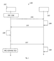
- Fig. 1 depicts schematically a sequence diagram for controlling the connection in a telecommunications network 100 according to a first embodiment.
- a network node 101 and UE 102 are connectable via a mmW link.
- the mmW link connects the UE to a mmAP of the telecommunications network 100.
- the network node 101 may be the mmAP.
- Radio resource control in this embodiment is implemented using mmW links as described below.
- the interface is used to transfer information regarding a beam reselection state parameter from the network node 101 to the UE 102 and to transfer information regarding a current beam reselection state of UE 102 from UE 102 to the network node 101.
- determining the beam reselection state parameter or the beam reselection state are described below as well.
- various other ways of determining the beam reselection state parameter or the beam reselection state may use the interface for transferring the corresponding information.
- information about the beam reselection state parameter is broadcast, for example in a system information broadcast according to 3GPP TS 136 331 V13.1.0 (2016-04 ).
- a corresponding RRC message may be modified or specifically defined to that end.
- UE 102 receives the beam reselection state parameter information.
- beam configuration information related to the mmAPs may be sent as well.
- UE 102 updates the beam reselection state based on the received beam reselection state parameter.
- Setting of the beam reselection state based on the beam reselection state parameter is as described below.
- UE 102 is initially in an idle state, e.g. a radio resource control idle state, RRC-IDLE state, according to 3GPP TS 136 331 V13.1.0 (2016-04 ). Then UE 102 transits into a connected state, e.g. a radio resource control connected state, RRC-CONNECTED state, according to 3GPP TS 136 331 V13.1.0 (2016-04 ).
- an idle state e.g. a radio resource control idle state, RRC-IDLE state
- UE 102 transits into a connected state, e.g. a radio resource control connected state, RRC-CONNECTED state, according to 3GPP TS 136 331 V13.1.0 (2016-04 ).
- a first message 103 e.g. a message RRCConnectionRequest according to 3GPP TS 136 331 V13.1.0 (2016-04 ), is sent by UE 102 to the network node 101 to request establishment of the link. Then UE 102 optionally executes an access point discovery for mmAP before sending the first message 103.
- the network node 101 determines in a step 104 a second message 105, e.g. a message RRCConnectionSetup according to 3GPP TS 136 331 V13.1.0 (2016-04 ).
- the second message 105 is sent to UE 102 as dedicated message.
- UE 102 Upon receipt of the second message 105, UE 102 sets up the connection in a step 106 as described below.
- a third message 107 e.g. a RRCConnectionSetupComplete according to 3GPP TS 136 331 V13.1.0 (2016-04 ) and including additional elements as described below, is determined by UE 102. Additional elements may be a beam reselection state or other reporting quantities related to beam reselection.
- a search for an optimum beam may be executed as described below.
- a beam selection criterion is set up depending on the received information and a predetermined beam reselection state is selected from a plurality of predetermined beam reselection states depending on the beam selection criterion as described below.
- the beam selection criterion may be used to select a beam when currently no beam is selected, or to reselect a beam.
- UE 102 Upon selection of a beam, UE 102 sends the third message 107, e.g. the RRCConnectionSetupComplete according to 3GPP TS 136 331 V13.1.0 (2016-04 ) and including additional elements as described below.
- the additional elements may be sent in a separate message (not depicted) as well. This way UE 102 informs the network about its beam reselection state when transitioning from idle to connected state.
- UE 102 After sending the third message 107, UE 102 arrives in connected state.
- the network node 101 With receipt of the third message, 107, the network node 101 receives information about the beam reselection state of the UE 102. This information may be used further in the network node 101 for determining the beam reselection parameter that is described below.
- a network node 101 and UE 102 are connectable via a radio link different from a mmW link.
- a radio link according to the well-known Long Term Evolution is used.
- the eNodeB may be the network node 101.
- the network node 101 is for example a control plane entity.
- Additional the telecommunications network 100 comprises at least one mmAP for connecting the UE to of the telecommunications network 100 via at least one mmW link. Radio resource control in this embodiment is implemented using the radio link different than the mmW link as described below.
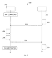
- Fig. 2 depicts schematically a sequence diagram for controlling the connection in telecommunications network 100 according to the second embodiment.
- UE 102 according to the second embodiment is initially in a connected state, e.g. a radio resource control connected state, RRC-CONNECTED state, according to 3GPP TS 136 331 V13.1.0 (2016-04 ). Then after a reestablishment of the connection UE 102 remains in connected state, e.g. the radio resource control connected state, RRC-CONNECTED state, according to 3GPP TS 136 331 V13.1.0 (2016-04 ).
- a connected state e.g. a radio resource control connected state, RRC-CONNECTED state
- the network node 101 determines in a step 202 that a reestablishment of a connection shall be performed.
- a first message 203 e.g. a message RRCConnectionReconfiguration according to 3GPP TS 136 331 V13.1.0 (2016-04 ) and including additional elements as described below, is sent by the network node 101 to UE 102 to request re-establishment of the link.
- the additional elements may be the beam reselection state parameter, or beam configuration information related to the mmAPs.
- the additional elements may be sent in a separate message (not depicted) as well.
- the first message 203 or the separate message is sent to UE 102 either as broadcast or as dedicated message.
- UE 102 Upon receipt of the first message 203, UE 102 sets up the connection in a step 204 as described below.
- the connection is set up depending on a beam reselection state parameter.
- the beam reselection state parameter is received in the first message 203.
- the beam reselection state parameter may be broadcast (not depicted in Figure 2 ) for example in a system information broadcast according to 3GPP TS 136 331 V13.1.0 (2016-04 ).
- a corresponding RRC message may be modified or specifically defined to that end..
- a search for an optimum beam may be executed as described below.
- a beam selection criterion may be configured depending on the received information and the predetermined beam reselection state is selected from a plurality of predetermined beam reselection states depending on the beam selection criterion as described below.
- UE 102 determines in a step 205 a second message 206, e.g. a message RRCConnectionReconfigurationComplete according to 3GPP TS 136 331 V13.1.0 (2016-04 ) and including additional elements as described below. Additional elements may be a beam reselection state or other reporting quantities related to beam reselection. The additional elements may be sent in a separate message (not depicted) as well.
- a second message 206 e.g. a message RRCConnectionReconfigurationComplete according to 3GPP TS 136 331 V13.1.0 (2016-04 ) and including additional elements as described below. Additional elements may be a beam reselection state or other reporting quantities related to beam reselection. The additional elements may be sent in a separate message (not depicted) as well.
- UE 102 After sending the second message 206, UE 102 remains in connected state.
- the network node 101 receives information about the beam reselection state of the UE 102. This information may be used further in the network node 101 for determining the beam reselection parameter that is described below.
- a dedicated message may be sent as well.
- the beam reselection state parameter sent to the UE 102 has a predetermined value. This value may be updated by the network node 101 based on the beam reselection state and/or other reporting quantities related to beam reselection.
- an anticipatory mechanism may be used. Once UE 102 is in connected state, statistics required for the anticipatory mechanism may be built on the fly with the help of channel quality feedbacks as well as the change of optimum beam index.
- anticipation may not be an option.
- the prediction or other statistics may be used to set a suitable beam reselection state parameter.
- the beam reselection state parameter captures an expected channel LOS uncertainty level based on information about the dynamics of a user and the environment of the user. This way, e.g. user movements, relative motion, or variations in the environment can be considered in the prediction or statistics when UE 102 is in idle and/or connected state.
- the dynamics of the UE 102 and/or the environment is captured with respect to the mmW coverage and the UE 102 provides this information to the telecommunications network 100 in messages 107 or 206 as described above.
- Beam reselection states associated to these dynamics and related parameters are defined as described below.
- Beam reselection states of UE 102 under mmW coverage may represent the movement randomness and/or channel uncertainty level.
- These beam reselection states may be updated and maintained by the UE 102 in idle and/or in connected state, e.g. in RRC_IDLE and RRC_CONNECTED state.
- the beam reselection states for example depend on the change of the best beams received and/or transmitted by the UE 102.
- the UE 102 in idle state, e.g. in RRC_IDLE state, receives only and receives and/or transmits in connected state, e.g. RRC_CONNECTED state.
- An exemplary criterion for selecting the beam reselection state may depend on the number of beam reselections NBR during a predetermined time period TBRmax, e.g. in the range of 0,1 ms to 1 second, in particular 0,1 ms to 1 ms or 1 ms to 10 ms or 10 ms to 100ms:
- the reselection state is selected from above described plurality of predetermined beam reselection states depending on a comparison of a first number of beam reselections with a second number number of beam reselections that occurred a time interval, e.g. the predetermined time period.
- the UE 102 may preferably be adapted to count consecutive reselections of beams or reselections between same beams when counting the number of beam reselections. For example, the number of beam reselections NBR is increased, if the same beam is reselected just after a predetermined number of reselections of other beams. In particular, when the same beam is reselected again after only one other beam was selected, this increments the number of beam reselections as well.
- the predetermined first number NBR_M is for example in the range of 1 to 10, in particular 2 to 10 or 2 to 5.
- the predetermined second number NBR_H is for example 10 to 20, or 10 to 30.
- the time period hysteresis TBRmaxHyst is for example in the range of 0,1 ms to 100 ms, in particular 0,1 ms to 19 ms or 10 ms to 100 ms.
- the UE 102 For beam reselection, the UE 102 measures available beams and evaluates the best beam. The currently best beam is labelled Serving Beam, SB.
- the UE 102 measures the Reference Signal Received Power, RSRP, and the Reference Signal Received Quality, RSRQ, level of the SB and evaluates the beam selection criterion.
- the beam selection criterion is for example fulfilled when Reference Signal Received Power, RSRP, of a beam exceeds a predetermined beam selection level of predetermined integer or non-integer value, e.g. 1 dB or 3 dB or 10 dB or in-between, and the Reference Signal Received Quality, RSRQ, exceeds a predetermined beam selection quality of predetermined integer or non-integer value, e.g. 1 dB, 3 dB or 10 dB or in-between.
- RSRP Reference Signal Received Power
- RSRQ Reference Signal Received Quality
- the beam selection method is carried out considering beams meeting the beam selection criterion.
- the UE 102 performs ranking of all beams that fulfill the beam selection criterion.
- the beams shall be ranked according to the Rsb, Rsn criteria given above. If a beam is ranked as the best beam the UE 102 performs beam reselection to that beam.
- UE 102 measures for example a received power or a received quality of the directional radio links, selects one of the directional radio links having the best received power or best received quality amongst the available directional radio link for connecting UE 102 to the telecommunications network 100.
- BRS beamReselectionState
- RRCConnectionSetupComplete a new information element or a field "beamReselectionState" is added in the RRC message "RRCConnectionSetupComplete”.
- BeamReselectionStateParameters may be used.
- BeamReselectionStateParameters contain:
- BeamReselectionStateParameters may contain parameters to determine the UE 120 beam reselection state.
- BeamReselectionStateParameters information element is defined as follows:
- the beam reselection state parameters are then broadcast by network node 101 in system information broadcast of the mmAP according to 3GPP TS 136 331 V13.1.0 (2016-04 ) or via the radio link other than mmW.
- the beam reselection state parameters may be sent by dedicated message to UE 102 as well.
- the UE 102 maintains a log of the number of beam changes "TotalNumBeamChange” in a given time "TimeWindowForCbservation” and a vector of cumulative duration "TotalTimeSpendInABeam” spend in a beam coverage, where the index of the vector will represent the beam index.
- the “TotalNumBeamChange” indicates a current number of beam reselections that occurred in a predetermined time interval "TimeWindowForObservation” of e.g. in the range of 1 ms to 10 seconds or more, in particular 1 ms to 10 ms, or 10 ms to 100 ms, e.g. 1 ms, 10 ms, 100 ms, 500 ms or 1 s.
- the RRC message "RRCConnectionSetupComplete" is used to indicate the states with, for example, 2 bits.
- Normal (no/low) BRS and Medium/High BRS are differentiated in only 1 bit to convey NBRS and MBRS/HBRS information to the network node 101.
- mapping For use 1 bit for BRS indication, the following mapping may be used:
- RRCConnectionSetupComplete For example the RRCConnectionSetupComplete message that is used to confirm the successful completion of an RRC connection establishment is modified with the following additional sequence added as last entry e.g. after RRCConnectionSetupComplete-v1250-IEs:
- xxxx is the revision/version number.
- This field indicates the UE beam reselection state (as defined above) just prior to UE going into RRC_CONNECTED state.
- the UE indicates the value of medium and high when being in Medium-mobility and High-mobility states respectively. Otherwise the UE indicates the value normal.
- MeasConfig information element is amended with an additional choice:
- EUTRA-UE-Variables contain in this case an additional import tag:
- the UE 102 preferably applies the similar rules as specified for speed dependent scaling rules. These are for example defined in 3GPP TS 36.304 V13.1.0 (2016-04 ), ⁇ 5.2.4.3.1.
- the aforementioned example defines three coarse levels classifying channel uncertainty in terms of Beam-Reselection States of UE 102. Further fine classification is also possible with additional beam reselection states using respective thresholds.
- mobility and location prediction methods are used for prediction of the movement.
- the UE based Beam Reselection State Estimate, BRSE, in RRC-IDLE may be used either as is or with some minor changes to share some form of mmW channel dynamics with the network during its transition to RRC-CONNECTED state.
- the network or the UE 102 may decide upon the mobility model and the prediction algorithm to be used for predicting the best beams. For instance, if the UE 102 is in normal BRS, the network may decide to use a simple low-complexity model for prediction according to A.W. Doff, Kishor Chandra, R.
- Venkatesha Prasad "Sensor Assisted Movement Identification and Prediction for Beamformed 60 GHz Links". Otherwise in case of high and/or medium BRS a sophisticated model can be used Cheffena, Michael “Doctoral thesis: Modeling and Prediction of Millimeter Wave length Channels or Paul Marinier, Gilles-Y. Delisle, Larbi Talbi," A coverage prediction technique for indoor wireless millimeter waves system", Springer Journal on Wireless Personal Communications, September 1996, Volume 3, Issue 3, pp 257-271 .
- the model requires the statistical parameters which represent the randomness in movements.
- the accurate location prediction depends upon the accurate dynamic estimation of the Gauss-Markov parameters, as well as the degree of variations in these parameters between location updates. This is described for example in B. Liang and Z. J. Haas, "Predictive distance-based mobility management for PCS networks," INFOCOM '99. Eighteenth Annual Joint Conference of the IEEE Computer and Communications Societies. Proceedings. IEEE, New York, NY, 1999, pp. 1377-1384 vol.3 .
- a parameter estimation window could be chosen such that it is small enough for the mobile movement to remain approximately stationary but large enough to provide sufficient amount of data samples.
- log records could be used to estimate model parameters for initialization phase of the algorithm.
- the BRS may then provide a parameter estimation window size for further update of parameters during RRC CONNECTED STATE. If high BRS is indicated then the parameter estimation window size for parameter update could be shorter and if normal BRS is indicated then it could be longer
- a Controlling Node may manage the mmAP in Multi Connectivity Clusters, MC-clusters.
- the network node 101 may be configured as the CoN.
- the CoN may be adapted to differentiate between mmAPs with respect to the following classification:
- Context means information related to the identity of the UE 102 and/or to the capabilities and/or requirements the UE 102 has regarding mmW data transmission.
- the network node 101 can decide how many mmAPs shall be prepared for CDPS and CPS.
- a multi connectivity manager may be used in a mmW overlay network assisted by another radio network not using mmW connections.
- the multi connectivity manager is for example the network node 101.
- the multi connectivity manager may use the BRS indication to decide whether to enable the mmW connectivity with the currently reported best mmAP or not.
- Mobility states estimates are commonly used to set the RRC-Inactivity timer values. It has been shown by many studies that at lower mobile speeds, it is better to maintain the UE 102 in connected mode. This corresponds to setting the RRC inactivity timer to infinity. At medium/high speeds, it is better to set the RRC inactivity timer to move the UE 102 into idle based on traffic activity. In the example, the RRC-inactivity timer is used to detect the radio inactivity of the UE 102. Upon the successful timer overrun, the connection with UE 102 is released by the network node 101, e.g. by means of a S1 Connection Release Procedure.
- BRS may be used on top of mobility states for a better estimation of the RRC inactivity timer.
- the RRC inactivity timer is configured for example based on the mobility states according to 3GPP TS 136.304 V. 13.1.0 (2016-04 ) and the beam reselection state:
- longer RRC-inactivity timer and shorter RRC-inactivity timer mean, that the RRC-inactivity timer is set to a value longer or shorter than a predetermined RRC-inactivity timer e.g. in the range of 0 to infinity, in particular 4 to 10 seconds, 1 ms to 1 second to 1 ms to 10 ms.
- longer RRC-inactivity timer refers to setting the RRC-inactivity timer to a larger value than aforementioned values.
- shorter RRC-inactivity timer refers to setting the RRC-inactivity timer to a shorter value than aforementioned values.
- the UE 102 may not have radio activity, but if HBR state is indicated by the UE 102, it will be switching beams quickly; consequently it will trigger frequent beam reports in uplink. In order to avoid these reports, it is good to have shorter RRC-inactivity timer.
- the telecommunications network 100 can provide better performance with respect to high reliability, high robustness, low latency, reduced handover failures and reduced radio link failures.
- the UE 102 can save energy and improve many algorithms, e.g. beam-tracking algorithm, by initializing with proper BRS. Based on the BRS, optimum initial search and mmAP detection mechanisms with minimum signalling overhead can be defined for the UE 102, e.g. by the network node 101.
- the UE 102 is a device for wireless data transmission in the telecommunications network 100.
- UE 102 comprises at least a processor, memory and a transceiver, and is adapted for performing the UE side of the method described above.
- the user equipment 102 operates in a wireless telecommunications network 100, in which directional radio beams are selectable for connecting the user equipment 102 to the wireless telecommunications network 100.
- the user equipment 102 comprises is configured to store at least two different beam reselection states, in particular aforementioned beam reselection stats. Furthermore user equipment 102 is configured to determine one of the at least two beam reselection states to operate in, in particular according to the method described above.
- user equipment 102 may be configured to track directional radio links used by the user equipment 102 over time for connecting the user equipment 102 to the wireless telecommunications network 100, in particular as described above. Furthermore in this case user equipment 102 may be configured to select the beam reselection state from the plurality of predetermined beam reselection states depending on information about the tracked directional radio links, in particular as described above.
- the network node 101 is a further device, e.g. an eNodeB, for wireless data transmission in the telecommunications network 100, wherein the network node 101 comprises at least a further processor, further memory and a further transceiver, and is adapted for performing the network side of the method described above.
- the network node 101 comprises at least a further processor, further memory and a further transceiver, and is adapted for performing the network side of the method described above.
- the transceivers 613 and 623 are connectable in the example for uplink via a radio communications link 630 according to the aforementioned LTE standard.
- UE User Equipment
- the radio network is e.g. an OFDM (Orthogonal Frequency Division Multiplex) type network, e.g. UF-OFDM, F-OFDM, ZT-s-OFDM, P-OFDM, FC-OFDM, or another multi-carrier network, e.g. FS-FBMC, QAM-FBMC, etc.
- OFDM Orthogonal Frequency Division Multiplex
- F-OFDM Frequency Division Multiplex
- ZT-s-OFDM P-OFDM
- FC-OFDM FC-OFDM
- another multi-carrier network e.g. FS-FBMC, QAM-FBMC, etc.
- QAM - Quadrature Amplitude Modulation and/or QPSK - Quadrature Phase Shift Keying are used as modulation technique.
- a network node could be implemented as a base station or a processing part of a base station.
- the base station could be an LTE eNodeB, a 5G transmission point, a WiFi access point, or else.
- the base station is in particular suitable to serve a radio cell and to connect user equipment inside the cell to the radio network.
- the base station is e.g. implemented as a stand-alone equipment including e.g. a processing part and a radio interface, or as a processing part and a remotely located so called RRH (Remote Radio Head).
- the processing part is e.g. implemented using a processor and a memory.
- the processor is implemented using e.g. a DSP, FPGA, or the like or a combination thereof.
- the memory is implemented using e.g., a RAM, ROM, DDR, Flash memory, or the like, or a combination thereof.
- the memory stores e.g. computer readable instructions, thus instructions executable by the processor.
- the processing part processes data and control info to be transmitted to the user equipment and generates messages including the data and/or control info to be transmitted, e.g. RRC Connection Request Message, RRC Connection Reconfiguration message, RRC Connection Complete message, RRC Connection Setup message, etc., and manages establishment, maintenance and release of an RRC connection between the UE and E-UTRAN and UE measurement reporting and control of the reporting.
- program storage devices e.g., digital data storage media, which are machine or computer readable and encode machine-executable or computer-executable programs of instructions, wherein said instructions perform some or all of the steps of said above-described methods.
- the program storage devices may be, e.g., digital memories, magnetic storage media such as a magnetic disks and magnetic tapes, hard drives, or optically readable digital data storage media.
- the embodiments are also intended to cover computers programmed to perform said steps of the above-described methods.
- processors may be provided through the use of dedicated hardware as well as hardware capable of executing software in association with appropriate software.
- the functions may be provided by a single dedicated processor, by a single shared processor, or by a plurality of individual processors, some of which may be shared.
- explicit use of the term "processor” should not be construed to refer exclusively to hardware capable of executing software, and may implicitly include, without limitation, digital signal processor (DSP) hardware, network processor, application specific integrated circuit (ASIC), field programmable gate array (FPGA), read only memory (ROM) for storing software, random access memory (RAM), and non-volatile storage.
- DSP digital signal processor
- ASIC application specific integrated circuit
- FPGA field programmable gate array
- ROM read only memory
- RAM random access memory
- non-volatile storage non-volatile storage.
- any switches shown in the FIGS. are conceptual only. Their function may be carried out through the operation of program logic, through dedicated logic, through the interaction of program control and dedicated logic, or even manually, the particular technique being selectable by the implementer as more specifically understood from the context.
- NFV network functions virtualization
- a virtualized network function of e.g. a sender or receiver may include at least one virtual machine running different software and processes, on top of standard high-volume servers, switches and storage, or a cloud computing infrastructure, instead of having customized hardware appliances for each network function.
- a sender or receiver function may be implemented in a computer program using a computer program product embodied on a non-transitory computer readable medium for performing operations, wherein the computer program product comprises instructions, that when executed by a processor, perform the operations of the specific eNodeB, network node or UE function.
Landscapes
- Engineering & Computer Science (AREA)
- Computer Networks & Wireless Communication (AREA)
- Signal Processing (AREA)
- Mobile Radio Communication Systems (AREA)
Priority Applications (1)
| Application Number | Priority Date | Filing Date | Title |
|---|---|---|---|
| EP16290154.0A EP3285408A1 (de) | 2016-08-17 | 2016-08-17 | Verfahren, vorrichtungen und computerprogramme für ein drahtlostelekommunikationsnetzwerk |
Applications Claiming Priority (1)
| Application Number | Priority Date | Filing Date | Title |
|---|---|---|---|
| EP16290154.0A EP3285408A1 (de) | 2016-08-17 | 2016-08-17 | Verfahren, vorrichtungen und computerprogramme für ein drahtlostelekommunikationsnetzwerk |
Publications (1)
| Publication Number | Publication Date |
|---|---|
| EP3285408A1 true EP3285408A1 (de) | 2018-02-21 |
Family
ID=56943445
Family Applications (1)
| Application Number | Title | Priority Date | Filing Date |
|---|---|---|---|
| EP16290154.0A Withdrawn EP3285408A1 (de) | 2016-08-17 | 2016-08-17 | Verfahren, vorrichtungen und computerprogramme für ein drahtlostelekommunikationsnetzwerk |
Country Status (1)
| Country | Link |
|---|---|
| EP (1) | EP3285408A1 (de) |
Citations (1)
| Publication number | Priority date | Publication date | Assignee | Title |
|---|---|---|---|---|
| US20160142117A1 (en) * | 2014-11-17 | 2016-05-19 | Samsung Electronics Co., Ltd. | Methods to calculate linear combination pre-coders for mimo wireless communication systems |
-
2016
- 2016-08-17 EP EP16290154.0A patent/EP3285408A1/de not_active Withdrawn
Patent Citations (1)
| Publication number | Priority date | Publication date | Assignee | Title |
|---|---|---|---|---|
| US20160142117A1 (en) * | 2014-11-17 | 2016-05-19 | Samsung Electronics Co., Ltd. | Methods to calculate linear combination pre-coders for mimo wireless communication systems |
Non-Patent Citations (15)
| Title |
|---|
| "3 Generation Partnership Project; Technical Specification Group Radio Access Network; Evolved Universal Terrestrial Radio Access (E-UTRA); User Equipment (UE) procedures in idle mode (Release 13)", 3GPP STANDARD; 3GPP TS 36.304, 3RD GENERATION PARTNERSHIP PROJECT (3GPP), MOBILE COMPETENCE CENTRE ; 650, ROUTE DES LUCIOLES ; F-06921 SOPHIA-ANTIPOLIS CEDEX ; FRANCE, vol. RAN WG2, no. V13.1.0, 30 March 2016 (2016-03-30), pages 1 - 43, XP051088473 * |
| "3rd Generation Partnership Project; Technical Specification Group Radio Access Network; Evolved Universal Terrestrial Radio Access (E-UTRA); Radio Resource Control (RRC); Protocol specification (Release 13)", 1 April 2016 (2016-04-01), XP051081790, Retrieved from the Internet <URL:http://www.3gpp.org/ftp/tsg_ran/WG2_RL2/Specifications/201603_final_specs_after_RAN_71/> [retrieved on 20160401] * |
| "RLM and RLF in HF NR", vol. RAN WG2, no. Gothenburg, Sweden; 20160822 - 20160826, 12 August 2016 (2016-08-12), XP051142724, Retrieved from the Internet <URL:http://www.3gpp.org/ftp/tsg_ran/WG2_RL2/TSGR2_95/Docs/> [retrieved on 20160812] * |
| 3GPP TS 136 331 V13.1. 0, April 2016 (2016-04-01) |
| 3GPP TS 136 331 V13.1..0, April 2016 (2016-04-01) |
| 3GPP TS 136 331 V13.1.0, April 2016 (2016-04-01) |
| 3GPP TS 136.304 V. 13.1.0, April 2016 (2016-04-01) |
| 3GPP TS 136.304 V13.1.0, April 2016 (2016-04-01) |
| 3GPP TS 36.304 V13.0.0, April 2016 (2016-04-01) |
| A. W. DOFF; KISHOR CHANDRA; R. VENKATESHA PRASAD, SENSOR ASSISTED MOVEMENT IDENTIFICATION AND PREDICTION FOR BEAMFORMED 60 GHZ LINKS |
| A. W. DOFF; KISHOR CHANDRA; R. VENKATESHA PRASAD: "Doctoral thesis: Modeling and Prediction of Millimeter Wave length Channels", March 2015, article "Sensor Assisted Movement Identification and Prediction for Beamformed 60 GHz Links and Cheffena" |
| B. LIANG; Z. J. HAAS: "INFOCOM '99. Eighteenth Annual Joint Conference of the IEEE Computer and Communications Societies. Proceedings", vol. 3, 1999, IEEE, article "Predictive distance-based mobility management for PCS networks", pages: 1377 - 1384 |
| F. BAI; A. HELMY: "Wireless Ad Hoc and Sensor Networks", June 2004, KLUWER ACADEMIC PUBLISHERS, article "A Survey of Mobility Modeling and Analysis in Wireless '' Ad Hoc Networks" |
| MICHAEL, DOCTORAL THESIS: MODELING AND PREDICTION OF MILLIMETER WAVE LENGTH CHANNELS |
| PAUL MARINIER; GILLES Y. DELISLE; LARBI TALBI: "Journal on Wireless Personal Communications", vol. 3, September 1996, SPRINGER, article "A coverage prediction technique for indoor wireless millimeter waves system", pages: 257 - 271 |
Similar Documents
| Publication | Publication Date | Title |
|---|---|---|
| US20250294517A1 (en) | Methods, ue and first network node for handling mobility information in a communications network | |
| US12063563B2 (en) | Handover method, base station, and terminal device | |
| US12127062B2 (en) | Timing advance for rach-less backhaul handover | |
| US20240040461A1 (en) | Ue, network node and methods for handling mobility information in a communications network | |
| US11477671B2 (en) | Methods and arrangements for radio link measurement configuration | |
| US10785692B2 (en) | Method and user equipment for mobility and classification based restricted measurement list creation in virtual cells | |
| KR20160108483A (ko) | 장치 이동성을 기초로 셀 측정을 수정하기 위한 장치 및 방법 | |
| US20240205875A1 (en) | First node, second node, or the method performed by the same | |
| WO2012152162A1 (zh) | 移动状态估计方法、用户设备及基站 | |
| WO2013104333A1 (zh) | 获取移动终端移动速度的方法、基站及终端 | |
| US10341891B2 (en) | User equipment adaptation of reporting triggers based on active set size | |
| US20240244499A1 (en) | Methods and apparatus for providing mobility state information | |
| CN109804669B (zh) | 网络节点和激活无线通信网络中的移动性过程的方法 | |
| EP3157182B1 (de) | Techniken zur messfilterung für drahtlose systeme | |
| TWI634809B (zh) | 宏輔助異構網路中用於測量以及連接控制的方法以及裝置 | |
| EP3285408A1 (de) | Verfahren, vorrichtungen und computerprogramme für ein drahtlostelekommunikationsnetzwerk | |
| KR20220148740A (ko) | 제1 노드, 제2 노드, 또는 제1 노드 및 제2 노드에 의해 수행되는 방법 | |
| RU2575259C2 (ru) | Обмен информацией о мобильности в сотовой радиосвязи | |
| CN121605323A (zh) | 用于执行跨多个小区区域的移动对象的雷达感知的方法 | |
| CN121773660A (zh) | 感知控制方法、装置、设备及存储介质 | |
| WO2025210191A1 (en) | Using an ai/ml model for handover and cell reselection | |
| KR20140070881A (ko) | 소형 셀 탐색 방법 및 그 장치 | |
| Alattas | Improving mobility management in 5G networks |
Legal Events
| Date | Code | Title | Description |
|---|---|---|---|
| PUAI | Public reference made under article 153(3) epc to a published international application that has entered the european phase |
Free format text: ORIGINAL CODE: 0009012 |
|
| AK | Designated contracting states |
Kind code of ref document: A1 Designated state(s): AL AT BE BG CH CY CZ DE DK EE ES FI FR GB GR HR HU IE IS IT LI LT LU LV MC MK MT NL NO PL PT RO RS SE SI SK SM TR |
|
| AX | Request for extension of the european patent |
Extension state: BA ME |
|
| RAP1 | Party data changed (applicant data changed or rights of an application transferred) |
Owner name: ALCATEL LUCENT |
|
| 17P | Request for examination filed |
Effective date: 20180821 |
|
| RBV | Designated contracting states (corrected) |
Designated state(s): AL AT BE BG CH CY CZ DE DK EE ES FI FR GB GR HR HU IE IS IT LI LT LU LV MC MK MT NL NO PL PT RO RS SE SI SK SM TR |
|
| 17Q | First examination report despatched |
Effective date: 20190117 |
|
| STAA | Information on the status of an ep patent application or granted ep patent |
Free format text: STATUS: THE APPLICATION IS DEEMED TO BE WITHDRAWN |
|
| 18D | Application deemed to be withdrawn |
Effective date: 20200212 |