EP3285530B1 - Verfahren und vorrichtungen zur übertragung von daten - Google Patents
Verfahren und vorrichtungen zur übertragung von daten Download PDFInfo
- Publication number
- EP3285530B1 EP3285530B1 EP16779540.0A EP16779540A EP3285530B1 EP 3285530 B1 EP3285530 B1 EP 3285530B1 EP 16779540 A EP16779540 A EP 16779540A EP 3285530 B1 EP3285530 B1 EP 3285530B1
- Authority
- EP
- European Patent Office
- Prior art keywords
- subframe
- enhanced
- length
- radio frame
- enhanced subframe
- Prior art date
- Legal status (The legal status is an assumption and is not a legal conclusion. Google has not performed a legal analysis and makes no representation as to the accuracy of the status listed.)
- Active
Links
Images








Classifications
-
- H—ELECTRICITY
- H04—ELECTRIC COMMUNICATION TECHNIQUE
- H04W—WIRELESS COMMUNICATION NETWORKS
- H04W28/00—Network traffic management; Network resource management
- H04W28/02—Traffic management, e.g. flow control or congestion control
- H04W28/06—Optimizing the usage of the radio link, e.g. header compression, information sizing, discarding information
-
- H—ELECTRICITY
- H04—ELECTRIC COMMUNICATION TECHNIQUE
- H04B—TRANSMISSION
- H04B7/00—Radio transmission systems, i.e. using radiation field
- H04B7/24—Radio transmission systems, i.e. using radiation field for communication between two or more posts
- H04B7/26—Radio transmission systems, i.e. using radiation field for communication between two or more posts at least one of which is mobile
- H04B7/2643—Radio transmission systems, i.e. using radiation field for communication between two or more posts at least one of which is mobile using time-division multiple access [TDMA]
- H04B7/2656—Radio transmission systems, i.e. using radiation field for communication between two or more posts at least one of which is mobile using time-division multiple access [TDMA] for structure of frame, burst
-
- H—ELECTRICITY
- H04—ELECTRIC COMMUNICATION TECHNIQUE
- H04W—WIRELESS COMMUNICATION NETWORKS
- H04W72/00—Local resource management
- H04W72/04—Wireless resource allocation
- H04W72/044—Wireless resource allocation based on the type of the allocated resource
- H04W72/0446—Resources in time domain, e.g. slots or frames
-
- H—ELECTRICITY
- H04—ELECTRIC COMMUNICATION TECHNIQUE
- H04L—TRANSMISSION OF DIGITAL INFORMATION, e.g. TELEGRAPHIC COMMUNICATION
- H04L5/00—Arrangements affording multiple use of the transmission path
- H04L5/003—Arrangements for allocating sub-channels of the transmission path
- H04L5/0053—Allocation of signalling, i.e. of overhead other than pilot signals
-
- H—ELECTRICITY
- H04—ELECTRIC COMMUNICATION TECHNIQUE
- H04W—WIRELESS COMMUNICATION NETWORKS
- H04W72/00—Local resource management
- H04W72/04—Wireless resource allocation
-
- H—ELECTRICITY
- H04—ELECTRIC COMMUNICATION TECHNIQUE
- H04W—WIRELESS COMMUNICATION NETWORKS
- H04W72/00—Local resource management
- H04W72/12—Wireless traffic scheduling
-
- H—ELECTRICITY
- H04—ELECTRIC COMMUNICATION TECHNIQUE
- H04W—WIRELESS COMMUNICATION NETWORKS
- H04W72/00—Local resource management
- H04W72/12—Wireless traffic scheduling
- H04W72/1263—Mapping of traffic onto schedule, e.g. scheduled allocation or multiplexing of flows
-
- H—ELECTRICITY
- H04—ELECTRIC COMMUNICATION TECHNIQUE
- H04L—TRANSMISSION OF DIGITAL INFORMATION, e.g. TELEGRAPHIC COMMUNICATION
- H04L5/00—Arrangements affording multiple use of the transmission path
- H04L5/0001—Arrangements for dividing the transmission path
- H04L5/0014—Three-dimensional division
- H04L5/0023—Time-frequency-space
Definitions
- the present invention relates to the field of wireless communication techniques, and in particular to a method and device for transmitting data.
- TDD Time division duplex
- the same frequency resources are used in uplink and downlink transmissions, and uplink/downward signals are transmitted in different slots.
- TD-SCDMA Time Division Synchronized Code Division Multiple Access
- 4G TD-LTE TD-SCDMA Long Term Evolution
- the division of uplink and downlink slots is static or semi-static, and usually the proportions of uplink and downlink slots are divided according to the cell type and approximate service proportions and remain unchanged in the process of network planning.
- a frame structure, as shown in Fig. 1 is used in the TDD mode of 3GPP (3rd Generation Partnership Project, 3rd Generation mobile communication standardization organization) LTE (Long Term Evolution) Rel (Release)-8/9/10/11/12/13.
- the user plane delay of an LTE system consists of eNB processing time, frame alignment time, TTI (transmission time interval) duration and user equipment processing time, wherein the frame alignment time is the waiting time from service arrival to the time when service can acquire air interface subframe transmission opportunities.
- a TD-LTE system using an existing frame structure can better adapt to the demand for different proportions of uplink and downlink services in the network, but has a user plane delay performance inferior to an FDD (frequency division duplex) system, and has the user plane delay twice that of an FDD system in some cases.
- FDD frequency division duplex
- an existing frame structure will increase the user plane delay of a TD-LTE system, and reduce the system performance.
- WO 2013/141770 A1 discloses dynamic configuration of subframes in a radio communications system.
- the technology disclosed provides the ability for a subframe to be dynamically configured in time division duplex (TDD) communications between a UE radio terminal (40) and a radio network node (10).
- a frame structure includes one or more subframes preconfigured as a downlink subframe, one or more subframes preconfigured as an uplink subframe, ans one or more dynamically configurable subframes.
- Each dynamically configurable subframe includes a guard time period and at least a downlink part for transporting a dynamically configurable amount of downlink information, and in some embodiments, uplink information.
- a configuration for dynamically configurable subframes is determined for transmission and/or reception between the UE radio terminal and the radio network node.
- the invention provides methods and devices for transmitting data, so as to solve the problems in the prior art that an existing frame structure will increase the user plane delay of an TD-LTE system and reduce the system performance.
- the network side device communicates with the user equipment through the radio frame, further including:
- determining, by the network side device, the radio frame includes:
- the enhanced subframe in the radio frame further includes an enhanced subframe of a first type
- M is equal to N; and/or the GP portion in the enhanced subframe is between the DL portion and the UL portion; or the GP portion in the enhanced subframe is at the end of the enhanced subframe; or the GP portion in the enhanced subframe is at the beginning of the enhanced subframe; and/or the radio frame includes at least one enhanced subframe with the GP portion and at least one enhanced subframe without the GP portion; or the radio frame includes at least one enhanced subframe, all of which have the GP portion; or the radio frame includes at least one enhanced subframe, none of which has the GP portion; and/or in a plurality of the enhanced subframes with GP portions in the radio frame, the positions of the GP portions in their respective enhanced subframes are completely identical or partially identical or completely different.
- the length of a downlink TTI of the enhanced subframe is less than the length of one subframe; and/or the length of an uplink TTI of the enhanced subframe is less than the length of one subframe.
- the length of a downlink TTI of the enhanced subframe is equal to the length of half a subframe; or the length of a downlink TTI of the enhanced subframe is equal to the length of the DL portion in the enhanced subframe; and/or the length of an uplink TTI of the enhanced subframe is equal to the length of half a subframe; or the length of an uplink TTI of the enhanced subframe is equal to the length of the UL portion in the enhanced subframe.
- the radio frame further includes at least one downlink subframe and/or at least one uplink subframe.
- the length of a downlink TTI of the downlink subframe is equal to or less than the length of one subframe; and/or the length of an uplink TTI of the uplink subframe is equal to or less than the length of one subframe.
- the method further includes: the network side device configuring the radio frame for the user equipment.
- communicating, by the user equipment, with the network side device through the radio frame further including:
- determining, by the user equipment, the radio frame includes: determining, by the user equipment, a length of the UL portion and a length of the DL portion in the enhanced subframe; wherein, the length of the UL portion is equal to or different from the length of the DL portion in the enhanced subframe.
- the enhanced subframe in the radio frame further includes an enhanced subframe of a first type; wherein, the DL portion is prior to the UL portion in the enhanced subframe of the first type; and/or the UL portion in the enhanced subframe includes N OFDM symbols, where N is a positive integer; and the DL portion in the enhanced subframe includes M OFDM symbols, where M is a positive integer; and/or wherein the length of the UL portion in different enhanced subframes of the radio frame is equal or different; and/or wherein the length of the DL portion in different enhanced subframes of the radio frame is equal or different; and/or the enhanced subframe further includes a guard period GP portion.
- M is equal to N; and/or the GP portion in the enhanced subframe is between the DL portion and the UL portion; or the GP portion in the enhanced subframe is at the end of the enhanced subframe; or the GP portion in the enhanced subframe is at the beginning of the enhanced subframe; and/or the radio frame includes at least one enhanced subframe with the GP portion and at least one enhanced subframe without the GP portion; or the radio frame includes at least one enhanced subframe, all of which have the GP portion; or the radio frame includes at least one enhanced subframe, none of which has the GP portion; and/or in a plurality of the enhanced subframes with GP portions in the radio frame, the positions of the GP portions in their respective enhanced subframes are completely identical or partially identical or completely different.
- the length of a downlink TTI of the enhanced subframe is less than the length of one subframe; and/or the length of an uplink TTI of the enhanced subframe is less than the length of one subframe.
- the length of a downlink TTI of the enhanced subframe is equal to the length of half a subframe; or the length of a downlink TTI of the enhanced subframe is equal to the length of the DL portion in the enhanced subframe; and/or the length of an uplink TTI of the enhanced subframe is equal to the length of half a subframe; or the length of an uplink TTI of the enhanced subframe is equal to the length of the UL portion in the enhanced subframe.
- the radio frame further includes at least one downlink subframe and/or at least one uplink subframe.
- the length of a downlink TTI of the downlink subframe is equal to or less than the length of one subframe; and/or the length of an uplink TTI of the uplink subframe is equal to or less than the length of one subframe.
- determining, by the user equipment, the radio frame including: determining, by the user equipment, the radio frame according to the configuration of a network side device.
- the first communication module is further configured for:
- the first determination module is configured for: determining a length of the UL portion and a length of the DL portion in the enhanced subframe; wherein, the length of the UL portion is equal to or different from the length of the DL portion in the enhanced subframe.
- the second communication module is further configured for:
- the second determination module is configured for: determining a length of the UL portion and a length of the DL portion in the enhanced subframe; wherein, the length of the UL portion is equal to or different from the length of the DL portion in the enhanced subframe.
- a radio frame for transmission between a network side device and a user equipment includes an enhanced subframe, which includes a UL (uplink) portion and a DL (downlink) portion.
- a TDD frame structure according to an embodiment of the invention can not only reduce the user plane delay on the basis of maintaining the service flexibility, but also maintain the backward compatibility of a system.
- a radio frame for transmission between a network side device and a user equipment includes an enhanced subframe, which includes a UL portion and a DL portion.
- a TDD frame structure in accordance with an embodiment of the invention can not only reduce the user plane delay while maintaining the service flexibility, but also maintain the backward compatibility of a system, as shown in the following description.
- a system for transmitting data in accordance with an embodiment of the invention includes a network side device 10 and a user equipment 20.
- the network side device 10 is configured for determining a radio frame, wherein the radio frame includes an enhanced subframe, and the enhanced subframe includes a UL portion and a DL portion; and communicates with the user equipment 20 through the radio frame.
- the user equipment 20 is configured for determining a radio frame, wherein the radio frame includes an enhanced subframe, and the enhanced subframe includes a UL portion and a DL portion; and communicates with the network side device 10 through the radio frame.
- a radio frame at least includes an enhanced subframe, which includes at least a DL portion and a UL portion.
- the frame structure in an embodiment of the invention may be used in a TD-LTE system, and may also be used in other systems.
- the network side device receives a part of or all of uplink pilot, uplink service data and uplink control signaling through the UL portion in the enhanced subframe.
- the user equipment transmits a part of or all of uplink pilot, uplink service data and uplink control signaling through the UL portion in the enhanced subframe.
- the network side device transmits a part of or all of downlink pilot, downlink service data and downlink control signaling through the DL portion.
- the user equipment receives a part of or all of downlink pilot, downlink service data and downlink control signaling through the DL portion.
- the lengths of the UL portions in different enhanced subframes of the radio frame are equal or different.
- the lengths of the DL portions in different enhanced subframes of the radio frame are equal or different.
- the enhanced subframe in an embodiment of the invention may further include a GP portion, and the network side device and the user equipment do not transmit signals in the GP portion.
- a GP portion in the enhanced subframe is between the DL portion and the UL portion.
- a GP portion in the enhanced subframe is at the end of the enhanced subframe.
- a GP portion in the enhanced subframe is at the beginning of the enhanced subframe.
- the positions of the GP portions in their respective enhanced subframes are completely identical or partially identical or completely different.
- the positions of the GP portions may be completely identical, and in each enhanced subframe of the radio frame, all GP portions may be at the end or at the front or in the middle of the enhanced frame.
- the network side device and the user equipment when determining a radio frame, the network side device and the user equipment further need to determine the length of the UL portion and the DL portion in the enhanced subframe; wherein the length of the UL portion and the length of the DL portion in the enhanced subframe are equal or different.
- the enhanced subframe of the radio frame in an embodiment of the invention includes an enhanced subframe of a first type and/or an enhanced subframe of a second type.
- the DL portion is prior to the UL portion in the enhanced subframe of the first type; and the UL portion is prior to the DL portion in the enhanced subframe of the second type.
- the DL portion is before the UL portion in the enhanced subframe of the first type, which is called the Type 1 enhanced subframe in this application; and the UL portion is before the DL portion in the enhanced subframe of the second type, which is called the Type 2 enhanced subframe in this application.
- the time length of the DL portion, time length of the GP portion and time length of the UL portion may be adjusted according to the uplink or downlink service demand, cell coverage area, etc., and the sum of the three time lengths is the time length of 1 subframe.
- the DL portion or the UL portion includes N OFDM symbols, where N is an integer.
- the length configuration of the three portions can be specified in a protocol or preconfigured by the system, or can be configured by broadcasting, user specific control signaling, or the like.
- a radio frame not only includes an enhanced subframe, but also may further include one or more downlink subframes, and/or, one or more uplink subframes,
- the downlink subframe may transmit downlink pilot, downlink service data, downlink control signaling, etc.; and the uplink subframe may transmit uplink pilot, uplink service data, uplink control signaling, etc.
- a radio frame not only includes an enhanced subframe, but also may further include one or more downlink subframes, and/or, one or more subframes, wherein the downlink subframe may transmit downlink pilot, downlink service data, downlink control signaling, etc.; and the uplink subframe may transmit uplink pilot, uplink service data, uplink control signaling, etc.
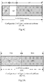
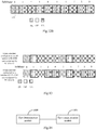
- Fig. 3A to Fig. 3C provide some typical configurations of type 1 enhanced subframes, wherein a GP is in an intermediate position.
- a GP at other positions is also suitable, which is easily understood by those skilled in the art, and is not illustrated any more.
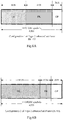
- Fig. 4A to Fig. 6C provide some typical configurations of type 2 enhanced subframes, and the enhanced subframes shown in the figures are different because of different configurations of GP portions.
- a figure where a GP is at the front is similar to the figures, and is not described in detail any more.
- time length of each portion in the figures is only illustrative, may also be set as other time lengths as required and according to simulation, etc., and is not described in detail any more herein.
- the length of a downlink TTI of the enhanced subframe is less than the length of one subframe.
- the length of a downlink TTI of the enhanced subframe is equal to the length of half a subframe; or the length of a downlink TTI of the enhanced subframe is equal to the length of the DL portion in the enhanced subframe.
- the length of an uplink TTI of the enhanced subframe is less than the length of one subframe.
- the length of an uplink TTI of the enhanced subframe is equal to the length of the UL portion in the enhanced subframe; or the length of an uplink TTI of the enhanced subframe is equal to the length of the UL portion in the enhanced subframe.
- the length of a TTI of a downlink subframe or an uplink subframe of a radio frame may be equal to the length of one subframe, or the length of a downlink TTI and/or an uplink TTI may be less than the length of one subframe.
- the length of one subframe is 1 ms or 0.2 ms
- the length of a corresponding TTI is equal to that of a subframe, i.e., 1 ms or 0.2 ms.
- a downlink subframe and/or an uplink subframe may include a plurality of TTIs.
- the length of a subframe is 1 ms, and the length of a TTI is 0.5 ms, then one subframe includes 2 TTIs.
- the length of a subframe is 1 ms, and the length of a TTI is 0.2 ms.
- the length of a subframe is 1 ms, and the length of a TTI is equal to the length of an OFDM symbol, e.g. about 70 us.
- the length of a subframe in a radio frame may be of any value.
- the length of a subframe in a system is 1 ms.
- the length of a subframe in a system is 0.2 ms.
- the radio frame includes at least one enhanced subframe, wherein the number of enhanced subframes, their positions in the radio frame, etc. are determined by a network device, and the determination result may be informed to a user equipment by way of protocol specification, network pre-configuration (e.g. system broadcasting or RRC (radio resource control) signaling), or dynamic control signaling indication (e.g. MAC (medium access control)) signaling or physical layer signaling PDCCH (physical downlink control channel) or the like.
- network pre-configuration e.g. system broadcasting or RRC (radio resource control) signaling
- dynamic control signaling indication e.g. MAC (medium access control)
- PDCCH physical downlink control channel
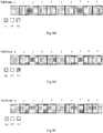
- all enhanced subframes are of a same type, i.e. type 1 enhanced subframe, and the length configurations of a DL portion, a GP portion and a UL portion in each enhanced subframe are identical.
- enhanced subframes of only one type may be used in a radio frame (only type 1 enhanced subframe is used or only type 2 enhanced subframe is used).
- different enhanced subframes may use different length configurations of DL, GP and UL.
- Fig. 7A to Fig. 7C are only illustrative, and are only used to teach those skilled in the art on how to specifically implement the invention. In the implementation process, a corresponding embodiment may be determined in conjunction with the practical requirements.
- Enhanced subframes #1 and #6 in Fig. 8 have an equal length configuration of DL, GP and UL, and other enhanced subframes use another length configuration of DL, GP and UL.
- enhanced subframes of different types may be simultaneously used.
- a type 1 enhanced subframe may use the above different structural configurations, as shown in examples of Fig. 3A to Fig. 3C , but not limited to Fig. 3A to Fig. 3C .
- a type 2 enhanced subframe may use the above different structural configurations, as shown in examples of Fig. 7 to Fig. 9 , but not limited to Fig. 4A to Fig. 6C .
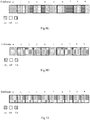
- Fig. 9A to Fig. 9H provide different embodiments of a radio frame using enhanced subframes of two types.
- a subframe ⁇ 1, 6 ⁇ uses a type 1 enhanced subframe
- a subframe ⁇ 3, 4, 8, 9 ⁇ uses a type 2 enhanced subframe.
- a subframe ⁇ 1, 4, 6, 9 ⁇ uses a type 1 enhanced subframe
- a subframe ⁇ 3, 8 ⁇ uses a type 2 enhanced subframe.
- a subframe ⁇ 1, 3, 6, 8 ⁇ uses a type 1 enhanced subframe
- a subframe ⁇ 4, 9 ⁇ uses a type 2 enhanced subframe.
- identical or different subframe structure configurations may be used between a plurality of enhanced subframes of a same type (referring to the lengths of DL, UL and/or GP portions in enhanced subframes).
- Other examples are similar and are not described in detail any more.
- a radio frame includes not only an enhanced subframe, but also a downlink subframe and an uplink subframe.
- a frame structure may only include an enhanced subframe; or a radio frame includes not only an enhanced subframe, but also either a downlink subframe or an uplink subframe.
- Fig. 10 to Fig. 11B respectively give three embodiments.
- the user plane delay is estimated below by taking a frame structure solution according to an embodiment of the invention applied in a TDD system as an example.
- an enhanced subframe can transmit not only a downlink service, but also an uplink service, and a radio frame includes a plurality of enhanced subframes. Therefore, the solution of the present invention can provide more opportunities for transmitting downlink services and/or uplink services. Compared with the existing TD-LTD frame structure, the solution of the invention has a beneficial effect of reducing the user plane delay.
- each subframe is 1 ms
- the length of a TTI in which a downlink service or an uplink service is respectively transmitted in a complete downlink subframe or uplink subframe is 1 ms.
- the length of a DL portion is 0.45 ms
- the length of a UL portion is 0.45 ms
- the length of a TTI in which a downlink service or an uplink service is respectively transmitted in a DL portion or a UL portion of an enhanced subframe is 0.45 ms.
- the processing time of 1 ms TTI data and 0.45 ms TTI data is respectively 1 ms and 0.5 ms before transmission by an eNB, and the corresponding processing time is respectively 1.5 ms and 1 ms during reception by a user equipment.
- the processing time of 1 ms TTI data and 0.45 ms TTI data is respectively 1 ms and 0.5 ms before transmission by a user equipment, and the corresponding processing time is respectively 1.5 ms and 1 ms during reception by an eNB.
- Table 1 and Table 2 are estimate results of an uplink and a downlink U plane delay for an embodiment in Fig. 12A . It can be seen that when HARQ (Hybrid Automatic Repeat Request) retransmission is not considered, the average uplink and downlink U plane delays are respectively 2.8 ms and 3 ms in an embodiment of the frame structure, and are significantly reduced, compared with 4 ms user plane delay of an existing LTE-FDD system and compared with the user plane delay of an existing TDD system (see 3GPP TR36.912). Therefore, the TDD frame structure presented in an embodiment of the invention has a beneficial effect of reducing the user plane delay of a system. Table 1 Estimate of an uplink U plane delay using an embodiment of a frame structure in Fig.
- a downlink subframe and an uplink subframe of a radio frame are respectively divided into 2 slots, and the lengths of a downlink TTI and an uplink TTI are defined to be equal to the slots.
- the length of each subframe is 1 ms
- the length of each TTI is 0.5 ms
- two TTIs are transmitted in one subframe.
- the length of a DL portion and the length of a UL portion are equal, correspond to DL and UL TTI lengths, and are approximately 0.5 ms.
- the processing time of 0.5 ms TTI is respectively 0.5 ms before transmission by an eNB, and the corresponding processing time is 1 ms during reception by a user equipment; and during uplink transmission, the processing time of 0.5 ms TTI data is respectively 0.5 ms before transmission by a user equipment, and the corresponding processing time is 1 ms during reception by an eNB.
- Table 3 and Table 4 are estimate results of an uplink and a downlink U plane delay for an embodiment in Fig. 12B . It can be seen that when HARQ retransmission is not considered, the average uplink and downlink U plane delays are respectively 2.6 ms and 2.75 ms in an embodiment of the frame structure, and are significantly reduced, compared with 4 ms user plane delay of an existing LTE-FDD system and compared with the user plane delay of an existing TDD system. Therefore, the TDD frame structure presented in the present invention has a beneficial effect of reducing the user plane delay of a system. Table 3 Estimate of an uplink U plane delay using an embodiment of a frame structure in Fig.
- a technical solution according to an embodiment of the invention can not only reduce the user plane delay, but also maintain the backward compatibility.
- the backward compatibility means that a carrier with a frame structure in the invention in an LTE-TDD system can access to not only an enhanced LTE-TDD user equipment (e.g. 3GPP LTE Rel-14 user equipment) supporting a solution of the invention, but also a low version LTE-TDD user equipment (e.g. a user equipment prior to 3GPP LTE Rel-13).
- the specific method includes configuring much uplink UL-DL configuration A on an old version LTE-TDD user equipment, configuring an enhanced subframe presented in the invention only on some uplink subframes of A, and configuring UL-DL configuration B corresponding to the result on an enhanced LTE-TDD user equipment.
- Fig. 13 provides an example, wherein a network configures an existing UL-DL configuration #0 and an existing special subframe configuration on a low version LTE-TDD user equipment configures an enhanced subframe on a subframe ⁇ 3, 4, 8, 9 ⁇ of a radio frame, and configures a corresponding frame structure on an enhanced LTE-TDD user equipment.
- the network schedules a low version LTE-TDD user equipment only in a subframe ⁇ 0, 1, 2, 5, 6, 7 ⁇ , and can schedule an enhanced LTE-TDD user equipment in all subframes.
- one radio frame is used as a unit for description.
- use of other time period as a unit is not excluded.
- subframe type and structure are configured with a half radio frame, a plurality of radio frames or any time as a unit, and the frame structure solutions thus obtained and corresponding embodiments also fall within the scope of protection of the invention.
- a solution provided in an embodiment of the invention is not limited to a subframe length in a system, 1 ms subframe structure identical to an existing LTE system may be used, and a shorter subframe length, e.g. 0.2 ms, may also be used as required. After using a shorter subframe length, the solution provided in an embodiment of the invention will have a lower user plane delay.
- a first network side device in a system for transmitting data includes:
- the first communication module 1401 is configured for:
- the first determination module 1400 is configured for:
- the enhanced subframe in the radio frame includes an enhanced subframe of a first type and/or an enhanced subframe of a second type; wherein, the DL portion is prior to the UL portion in the enhanced subframe of the first type; and the UL portion is prior to the DL portion in the enhanced subframe of the second type.
- the UL portion in the enhanced subframe includes N OFDM symbols, where N is a positive integer; and the DL portion in the enhanced subframe includes M OFDM symbols, where M is a positive integer.
- M is equal to N.
- the length of the UL portion in different enhanced subframes of the radio frame is equal or different.
- the length of the DL portion in different enhanced subframes of the radio frame is equal or different.
- the enhanced subframe further includes a guard period GP portion.
- the GP portion in the enhanced subframe is between the DL portion and the UL portion; or the GP portion in the enhanced subframe is at the end of the enhanced subframe; or the GP portion in the enhanced subframe is at the beginning of the enhanced subframe.
- the radio frame includes at least one enhanced subframe with the GP portion and at least one enhanced subframe without the GP portion; or the radio frame includes at least one enhanced subframe, all of which have GP portion; or the radio frame includes at least one enhanced subframe, none of which has the GP portion.
- the positions of the GP portions in their respective enhanced subframes are completely identical or partially identical or completely different.
- the length of a downlink TTI of the enhanced subframe is less than the length of one subframe; and/or the length of an uplink TTI of the enhanced subframe is less than the length of one subframe.
- the length of a downlink TTI of the enhanced subframe is equal to the length of half a subframe; or the length of a downlink TTI of the enhanced subframe is equal to the length of the DL portion in the enhanced subframe; and/or the length of an uplink TTI of the enhanced subframe is equal to the length of half a subframe; or the length of an uplink TTI of the enhanced subframe is equal to the length of the UL portion in the enhanced subframe.
- the radio frame further includes at least one downlink subframe and/or at least one uplink subframe.
- the length of a downlink TTI of the downlink subframe is equal to or less than the length of one subframe; and/or the length of an uplink TTI of the uplink subframe is equal to or less than the length of one subframe.
- the first communication module is further configured for radio frame configuration of the user equipment.
- a first user equipment in a system for transmitting data includes:
- the second communication module 1501 is configured for:
- the second determination module 1500 is configured for:
- the enhanced subframe in the radio frame includes an enhanced subframe of a first type and/or an enhanced subframe of a second type; wherein, the DL portion is prior to the UL portion in the enhanced subframe of the first type; and the UL portion is prior to the DL portion in the enhanced subframe of the second type.
- the UL portion in the enhanced subframe includes N OFDM symbols, where N is a positive integer; and the DL portion in the enhanced subframe includes M OFDM symbols, where M is a positive integer.
- M is equal to N.
- the length of the UL portion in different enhanced subframes of the radio frame is equal or different.
- the length of the DL portion in different enhanced subframes of the radio frame is equal or different.
- the enhanced subframe further includes a guard period GP portion.
- a GP portion in the enhanced subframe is between the DL portion and the UL portion; or a GP portion in the enhanced subframe is at the end of the enhanced subframe; or a GP portion in the enhanced subframe is at the beginning of the enhanced subframe.
- the radio frame includes at least one enhanced subframe with the GP portion and at least one enhanced subframe without the GP portion; or the radio frame includes at least one enhanced subframe, all of which have the GP portion; or the radio frame includes at least one enhanced subframe, none of which has the GP portion.
- the positions of the GP portions in their respective enhanced subframes are completely identical or partially identical or completely different.
- the length of a downlink TTI of the enhanced subframe is less than the length of one subframe; and/or the length of an uplink TTI of the enhanced subframe is less than the length of one subframe.
- the length of a downlink TTI of the enhanced subframe is equal to the length of half a subframe; or the length of a downlink TTI of the enhanced subframe is equal to the length of the DL portion in the enhanced subframe; and/or the length of an uplink TTI of the enhanced subframe is equal to the length of half a subframe; or the length of an uplink TTI of the enhanced subframe is equal to the length of the UL portion in the enhanced subframe.
- the radio frame further includes at least one downlink subframe and/or at least one uplink subframe.
- the length of a downlink TTI of the downlink subframe is equal to or less than the length of one subframe; and/or the length of an uplink TTI of the uplink subframe is equal to or less than the length of one subframe.
- the user equipment determines the radio frame, including: the user equipment determining the radio frame according to the configuration of a network side device.
- a second network side device in a system for transmitting data includes: a processor 1601, configured for reading programs in a memory 1604 and executing the following processes:
- the processor 1601 is configured for:
- the processor 1601 is configured for:
- the enhanced subframe in the radio frame includes an enhanced subframe of a first type and/or an enhanced subframe of a second type; wherein, the DL portion is prior to the UL portion in the enhanced subframe of the first type; and the UL portion is prior to the DL portion in the enhanced subframe of the second type.
- the UL portion in the enhanced subframe includes N OFDM symbols, where N is a positive integer; and the DL portion in the enhanced subframe includes M OFDM symbols, where M is a positive integer.
- M is equal to N.
- the length of the UL portion in different enhanced subframes of the radio frame is equal or different.
- the length of the DL portion in different enhanced subframes of the radio frame is equal or different.
- the enhanced subframe further includes a guard period GP portion.
- the GP portion in the enhanced subframe is between the DL portion and the UL portion; or the GP portion in the enhanced subframe is at the end of the enhanced subframe; or the GP portion in the enhanced subframe is at the beginning of the enhanced subframe.
- the radio frame includes at least one enhanced subframe with the GP portion and at least one enhanced subframe without the GP portion; or the radio frame includes at least one enhanced subframe, all of which have GP portion; or the radio frame includes at least one enhanced subframe, none of which has the GP portion.
- the positions of the GP portions in their respective enhanced subframes are completely identical or partially identical or completely different.
- the length of a downlink TTI of the enhanced subframe is less than the length of one subframe; and/or the length of an uplink TTI of the enhanced subframe is less than the length of one subframe.
- the length of a downlink TTI of the enhanced subframe is equal to the length of half a subframe; or the length of a downlink TTI of the enhanced subframe is equal to the length of the DL portion in the enhanced subframe; and/or the length of an uplink TTI of the enhanced subframe is equal to the length of half a subframe; or the length of an uplink TTI of the enhanced subframe is equal to the length of the UL portion in the enhanced subframe.
- the radio frame further includes at least one downlink subframe and/or at least one uplink subframe.
- the length of a downlink TTI of the downlink subframe is equal to or less than the length of one subframe; and/or the length of an uplink TTI of the uplink subframe is equal to or less than the length of one subframe.
- the first communication module is further configured for: configuring the radio frame for the user equipment.
- the bus 1600 may include any number of interconnected buses and bridges, and links various circuits including one or more processors represented by a processor 1601 and memories represented by a memory 1604 together.
- the bus 1600 can further link a variety of other circuits, such as peripheral equipment, a voltage regulator and a power management circuit, together, all of which are well known in this field, and are not further described any more herein.
- the bus interface 1603 provides an interface between the bus 1600 and a transceiver 1602.
- the transceiver 1602 may be one element or a plurality of elements, e.g. a plurality of receivers and transmitters, and provides units for communicating with various other devices on the transmission medium.
- Data processed by the processor 1601 are transmitted over a radio medium by an antenna 1605. Furthermore, the antenna 1605 further receives data and transmits the data to the processor 1601.
- the processor 1601 is responsible for managing the bus 1600 and regular processing, and can also provide various functions, including timing, peripheral interfaces, voltage regulation, power management, and other control functions.
- the memory 1604 can be configured for storing data used by the processor 1601 when executing an operation.
- the processor 1601 may be a CPU (central processing unit), an ASIC (Application Specific Integrated Circuit), a FPGA (Field-Programmable Gate Array) or a CPLD (Complex Programmable Logic Device).
- CPU central processing unit
- ASIC Application Specific Integrated Circuit
- FPGA Field-Programmable Gate Array
- CPLD Complex Programmable Logic Device
- a second user equipment in a system for transmitting data includes: a processor 1701, configured for reading programs in a memory 1704 and executing the following processes:
- the processor 1701 is configured for:
- the processor 1701 is configured for:
- the enhanced subframe in the radio frame includes an enhanced subframe of a first type and/or an enhanced subframe of a second type; wherein, the DL portion is prior to the UL portion in the enhanced subframe of the first type; and the UL portion is prior to the DL portion in the enhanced subframe of the second type.
- the UL portion in the enhanced subframe includes N OFDM symbols, where N is a positive integer; and the DL portion in the enhanced subframe includes M OFDM symbols, where M is a positive integer.
- M is equal to N.
- the length of the UL portion in different enhanced subframes of the radio frame is equal or different.
- the length of the DL portion in different enhanced subframes of the radio frame is equal or different.
- the enhanced subframe further includes a guard period GP portion.
- the GP portion in the enhanced subframe is between the DL portion and the UL portion; or the GP portion in the enhanced subframe is at the end of the enhanced subframe; or the GP portion in the enhanced subframe is at the beginning of the enhanced subframe.
- the radio frame includes at least one enhanced subframe with the GP portion and at least one enhanced subframe without the GP portion; or the radio frame includes at least one enhanced subframe, all of which have the GP portion; or the radio frame includes at least one enhanced subframe, none of which has the GP portion.
- the positions of the GP portions in their respective enhanced subframes are completely identical or partially identical or completely different.
- the length of a downlink TTI of the enhanced subframe is less than the length of one subframe; and/or the length of an uplink TTI of the enhanced subframe is less than the length of one subframe.
- the length of a downlink TTI of the enhanced subframe is equal to the length of half a subframe; or the length of a downlink TTI of the enhanced subframe is equal to the length of the DL portion in the enhanced subframe; and/or the length of an uplink TTI of the enhanced subframe is equal to the length of half a subframe; or the length of an uplink TTI of the enhanced subframe is equal to the length of the UL portion in the enhanced subframe.
- the radio frame further includes at least one downlink subframe and/or at least one uplink subframe.
- the length of a downlink TTI of the downlink subframe is equal to or less than the length of one subframe; and/or the length of an uplink TTI of the uplink subframe is equal to or less than the length of one subframe.
- the user equipment determines the radio frame, including: the user equipment determining the radio frame according to the configuration of a network side device.
- the bus 1700 may include any number of interconnected buses and bridges, and links various circuits including one or more processors represented by a processor 1701 and memories represented by a memory 1704 together.
- the bus 1700 can further link a variety of other circuits, such as peripheral equipment, a voltage regulator and a power management circuit, together, all of which are well known in this field, and are not further described any more herein.
- the bus interface 1703 provides an interface between the bus 1700 and a transceiver 1702.
- the transceiver 1702 may be one element or a plurality of elements, e.g. a plurality of receivers and transmitters, and provides units for communicating with various other devices on the transmission medium.
- the transceiver 1702 receives external data from other devices.
- the transceiver 1702 is used for transmitting data processed by the processor 1701 to other devices.
- a user interface 1705 may be further provided, e.g. a keypad, a displayer, a loudspeaker, a microphone, or a joy stick.
- the processor 1701 is responsible for managing the bus 1700 and regular processing, e.g. the foregoing operating a usual operating system.
- the memory 1704 can be configured for storing data used by the processor 1701 when executing an operation.
- the processor 1701 may be a CPU, an ASIC, a FPGA or a CPLD.
- an embodiment of the present invention further provides a first method for transmitting data. Because the device corresponding to this method is a network side device in a system for transmitting data according to an embodiment of the present invention, and the problem solving principle of the method is similar to the device, the implementation of the device can be referred to for the implementation of this method, and the repetition is not described in detail any more.
- a first method for transmitting data in a system for transmitting data includes the following steps.
- Step 1800 a network side device determines a radio frame, wherein the radio frame includes an enhanced subframe, and the enhanced subframe includes a UL portion and a DL portion.
- Step 1801 the network side device communicates with a user equipment through the radio frame.
- the network side device communicates with the user equipment through the radio frame, including:
- the network side device determines the radio frame, including:
- the enhanced subframe in the radio frame includes an enhanced subframe of a first type and/or an enhanced subframe of a second type; wherein, the DL portion is prior to the UL portion in the enhanced subframe of the first type; and the UL portion is prior to the DL portion in the enhanced subframe of the second type.
- the UL portion in the enhanced subframe includes N OFDM symbols, where N is a positive integer; and the DL portion in the enhanced subframe includes M OFDM symbols, where M is a positive integer.
- M is equal to N.
- the length of the UL portion in different enhanced subframes of the radio frame is equal or different.
- the length of the DL portion in different enhanced subframes of the radio frame is equal or different.
- the enhanced subframe further includes a guard period GP portion.
- the GP portion in the enhanced subframe is between the DL portion and the UL portion; or the GP portion in the enhanced subframe is at the end of the enhanced subframe; or the GP portion in the enhanced subframe is at the beginning of the enhanced subframe.
- the radio frame includes at least one enhanced subframe with the GP portion and at least one enhanced subframe without the GP portion; or the radio frame includes at least one enhanced subframe, all of which have the GP portion; or the radio frame includes at least one enhanced subframe, none of which has the GP portion.
- the positions of the GP portions in their respective enhanced subframes are completely identical or partially identical or completely different.
- the length of a downlink TTI of the enhanced subframe is less than the length of one subframe; and/or the length of an uplink TTI of the enhanced subframe is less than the length of one subframe.
- the length of a downlink TTI of the enhanced subframe is equal to the length of half a subframe; or the length of a downlink TTI of the enhanced subframe is equal to the length of the DL portion in the enhanced subframe; and/or, the length of an uplink TTI of the enhanced subframe is equal to the length of half a subframe; or the length of an uplink TTI of the enhanced subframe is equal to the length of the UL portion in the enhanced subframe.
- the radio frame further includes at least one downlink subframe and/or at least one uplink subframe.
- the length of a downlink TTI of the downlink subframe is equal to or less than the length of one subframe; and/or the length of an uplink TTI of the uplink subframe is equal to or less than the length of one subframe.
- the method further includes: the network side device configuring the radio frame for the user equipment.
- an embodiment of the invention further provides a second method for transmitting data. Because the device corresponding to this method is a user equipment in a system for transmitting data according to an embodiment of the invention, and the problem solving principle of the method is similar to the device, the implementation of the device can be referred to for the implementation of this method, and the repetition is not described in detail any more.
- a second method for transmitting data in a system for transmitting data includes the following steps.
- Step 1900 a user equipment determines a radio frame, wherein the radio frame includes an enhanced subframe, and the enhanced subframe includes a UL portion and a DL portion.
- Step 1901 the user equipment communicates with a network side device through the radio frame.
- the user equipment communicates with the network side device through the radio frame, including:
- the user equipment determines the radio frame, including:
- the enhanced subframe in the radio frame includes an enhanced subframe of a first type and/or an enhanced subframe of a second type; wherein, the DL portion is prior to the UL portion in the enhanced subframe of the first type; and the UL portion is prior to the DL portion in the enhanced subframe of the second type.
- the UL portion in the enhanced subframe includes N OFDM symbols, where N is a positive integer; and the DL portion in the enhanced subframe includes M OFDM symbols, where M is a positive integer.
- M is equal to N.
- the length of the UL portion in different enhanced subframes of the radio frame is equal or different.
- the length of the DL portion in different enhanced subframes of the radio frame is equal or different.
- the enhanced subframe further includes a guard period GP portion.
- the GP portion in the enhanced subframe is between the DL portion and the UL portion; or the GP portion in the enhanced subframe is at the end of the enhanced subframe; or the GP portion in the enhanced subframe is at the beginning of the enhanced subframe.
- the radio frame includes at least one enhanced subframe with the GP portion and at least one enhanced subframe without the GP portion; or the radio frame includes at least one enhanced subframe, all of which have the GP portion; or the radio frame includes at least one enhanced subframe, none of which has the GP portion.
- the positions of the GP portions in their respective enhanced subframes are completely identical or partially identical or completely different.
- the length of a downlink TTI of the enhanced subframe is less than the length of one subframe; and/or the length of an uplink TTI of the enhanced subframe is less than the length of one subframe.
- the length of a downlink TTI of the enhanced subframe is equal to the length of half a subframe; or the length of a downlink TTI of the enhanced subframe is equal to the length of the DL portion in the enhanced subframe; and/or the length of an uplink TTI of the enhanced subframe is equal to the length of half a subframe; or the length of an uplink TTI of the enhanced subframe is equal to the length of the UL portion in the enhanced subframe.
- the radio frame further includes at least one downlink subframe and/or at least one uplink subframe.
- the length of a downlink TTI of the downlink subframe is equal to or less than the length of one subframe; and/or the length of an uplink TTI of the uplink subframe is equal to or less than the length of one subframe.
- the user equipment determines the radio frame, including: the user equipment determining the radio frame according to the configuration of a network side device.
- a radio frame for transmission between a network side device and a user equipment includes an enhanced subframe, which includes a UL portion and a DL portion.
- a TDD frame structure according to an embodiment of the invention can not only reduce the user plane delay on the basis of maintaining the service flexibility, but also maintain the backward compatibility of a system.
- These computer program instructions can also be loaded into a computer or other programmable data processing equipment, so as to execute a series of operation steps on the computer or other programmable devices to generate processing realized by the computer, so that an instruction executed on a computer or other programmable devices provides steps for implementing functions specified in one or more processes of a process diagram and/or one or more boxes of a block diagram.
Landscapes
- Engineering & Computer Science (AREA)
- Signal Processing (AREA)
- Computer Networks & Wireless Communication (AREA)
- Mobile Radio Communication Systems (AREA)
Claims (19)
- Verfahren zum Übertragen von Daten, umfassend:Bestimmen (1800), durch eine netzwerkseitige Vorrichtung, eines Funkframes, wobei der Funkframe einen erweiterten Subframe umfasst und der erweiterte Subframe einen Uplink-, UL-, Teil und einen Downlink-, DL-, Teil umfasst; undKommunizieren (1801), der netzwerkseitigen Vorrichtung, mit einem Benutzergerät durch den Funkframe;dadurch gekennzeichnet, dass der erweiterte Subframe in dem Funkframe ein erweiterter Subframe eines zweiten Typs ist; wobei der UL-Teil vor dem DL-Teil in dem erweiterten Subframe des zweiten Typs liegt.
- Verfahren nach Anspruch 1, wobei das Kommunizieren (1801) durch die netzwerkseitige Vorrichtung mit dem Benutzergerät über den Funkframe ferner umfasst:Empfangen eines Teils der oder aller Uplink-Pilotdaten, Uplink-Dienstdaten und Uplink-Steuersignalisierung durch die netzwerkseitige Vorrichtung über den UL-Teil im erweiterten Subframe; und/oderÜbertragen, durch die netzwerkseitige Vorrichtung, eines Teils der oder aller Downlink-Pilotdaten, Downlink-Dienstdaten und Downlink-Steuersignalisierung durch den DL-Teil in dem erweiterten Subframe.
- Verfahren nach Anspruch 1, wobei das Bestimmen des Funkframes durch die netzwerkseitige Vorrichtung umfasst:Bestimmen, durch die netzwerkseitige Vorrichtung, einer Länge des UL-Teils und einer Länge des DL-Teils in dem erweiterten Subframe;wobei die Länge des UL-Teils gleich oder unterschiedlich von der Länge des DL-Teils in dem erweiterten Subframe ist.
- Verfahren nach Anspruch 3, wobei der UL-Teil in dem erweiterten Subframe N orthogonale Frequenzmultiplex-OFDM-Symbole umfasst, wobei N eine positive ganze Zahl ist; und der DL-Teil in dem erweiterten Subframe M OFDM-Symbole umfasst, wobei M eine positive ganze Zahl ist;
und/oder
wobei die Länge des UL-Teils in unterschiedlichen erweiterten Subframes des Funkframes gleich oder unterschiedlich ist; und/oder
wobei die Länge des DL-Teils in unterschiedlichen erweiterten Subframes des Funkframes gleich oder unterschiedlich ist; und/oder
wobei der erweiterte Subframe ferner einen Schutzperiodenteil, GP-Teil, umfasst. - Verfahren nach einem der Ansprüche 1 bis 4, wobei der Funkframe ferner mindestens einen Downlink-Subframe und/oder mindestens einen Uplink-Subframe umfasst.
- Verfahren nach einem der Ansprüche 1 bis 5, ferner umfassend:
Konfigurieren des Funkframes für das Benutzergerät durch die netzwerkseitige Vorrichtung. - Verfahren zum Übertragen von Daten, umfassend:Bestimmen (1900), durch ein Benutzergerät, eines Funkframes, wobei der Funkframe einen erweiterten Subframe umfasst und der erweiterte Subframe einen Uplink-, UL-, Teil und einen Downlink-, DL-, Teil umfasst; undKommunizieren (1901), durch das Benutzergerät, mit einer netzwerkseitigen Vorrichtung durch den Funkframe;dadurch gekennzeichnet, dass der erweiterte Subframe in dem Funkframe ein erweiterter Subframe eines zweiten Typs ist; wobei der UL-Teil vor dem DL-Teil in dem erweiterten Subframe des zweiten Typs liegt.
- Verfahren nach Anspruch 7, wobei das Kommunizieren (1901) durch das Benutzergerät mit der netzwerkseitigen Vorrichtung über den Funkframe ferner umfasst:Übertragen eines Teils der oder aller Uplink-Pilotdaten, Uplink-Dienstdaten und Uplink-Steuersignalisierung durch das Benutzergerät über den UL-Teil im erweiterten Subframe; und/oderEmpfangen, durch das Benutzergerät, eines Teils der oder aller Downlink-Pilotdaten, Downlink-Dienstdaten und Downlink-Steuersignalisierung durch den DL-Teil in dem erweiterten Subframe.
- Verfahren nach Anspruch 8, wobei das Bestimmen des Funkframes durch das Benutzergerät umfasst:Bestimmen, durch das Benutzergerät, einer Länge des UL-Teils und einer Länge des DL-Teils in dem erweiterten Subframe;wobei die Länge des UL-Teils gleich oder unterschiedlich von der Länge des DL-Teils in dem erweiterten Subframe ist.
- Verfahren nach Anspruch 9, wobei der UL-Teil in dem erweiterten Subframe N OFDM-Symbole umfasst, wobei N eine positive ganze Zahl ist; und der DL-Teil in dem erweiterten Subframe M OFDM-Symbole umfasst, wobei M eine positive ganze Zahl ist; und/oder
wobei die Länge des UL-Teils in unterschiedlichen erweiterten Subframes des Funkframes gleich oder unterschiedlich ist; und/oder
wobei die Länge des DL-Teils in unterschiedlichen erweiterten Subframes des Funkframes gleich oder unterschiedlich ist; und/oder
wobei der erweiterte Subframe ferner einen Schutzperiodenanteil, GP-Teil, umfasst. - Verfahren nach Anspruch 10, wobei M gleich N ist; und/oder
wobei der GP-Teil in dem erweiterten Subframe zwischen dem DL-Teil und dem UL-Teil liegt; oder der GP-Teil in dem erweiterten Subframe am Ende des erweiterten Subframes liegt; oder der GP-Teil in dem erweiterten Subframe am Anfang des erweiterten Subframes liegt;
und/oder
wobei in mehreren der erweiterten Subframes mit GP-Teilen im Funkframe die Positionen der GP-Teile in ihren jeweiligen erweiterten Subframes vollständig identisch oder teilweise identisch oder vollständig unterschiedlich sind. - Verfahren nach einem der Ansprüche 7 bis 11, wobei der Funkframe ferner mindestens einen Downlink-Subframe und/oder mindestens einen Uplink-Subframe umfasst.
- Verfahren nach einem der Ansprüche 7 bis 11, wobei das Bestimmen des Funkframes durch das Benutzergerät umfasst:
Bestimmen des Funkframes durch das Benutzergerät gemäß der Konfiguration der netzwerkseitigen Vorrichtung. - Netzwerkseitigen Vorrichtung zum Übertragen von Daten, umfassend:ein erstes Bestimmungsmodul (1400), das ausgelegt ist zum, Bestimmen eines Funkframe, wobei der Funkframe einen erweiterten Subframe umfasst, und der erweiterte Subframe einen Uplink-, UL-, Teil und einen Downlink-, DL-, Teil umfasst; undein erstes Kommunikationsmodul (1401), das ausgelegt ist zum Kommunizieren mit einem Benutzergerät über den Funkframe;dadurch gekennzeichnet, dass der erweiterte Subframe in dem Funkframe ein erweiterter Subframe eines zweiten Typs ist; wobei der UL-Teil vor dem DL-Teil in dem erweiterten Subframe des zweiten Typs liegt.
- Netzwerkseitige Vorrichtung nach Anspruch 14, wobei das erste Kommunikationsmodul (1401) ferner ausgelegt ist zum:Empfangen eines Teils der oder aller Uplink-Pilotdaten, Uplink-Dienstdaten und Uplink-Steuersignalisierung über den UL-Teil in dem erweiterten Subframe; und/oderÜbertragen eines Teils der oder aller Downlink-Pilotdaten, Downlink-Dienstdaten und Downlink-Steuersignalisierung durch den DL-Teil in dem erweiterten Subframe.
- Netzwerkseitige Vorrichtung nach Anspruch 14, wobei das erste Bestimmungsmodul ausgelegt ist zum:Bestimmen einer Länge des UL-Teils und einer Länge des DL-Teils in dem erweiterten Subframe;wobei die Länge des UL-Teils gleich oder unterschiedlich von der Länge des DL-Teils in dem erweiterten Subframe ist.
- Benutzergerät zum Übertragen von Daten, umfassend:ein zweites Bestimmungsmodul (1500), das ausgelegt ist zum Bestimmen eines Funkframe, wobei der Funkframe einen erweiterten Subframe umfasst, und der erweiterte Subframe einen Uplink-, UL-, Teil und einen Downlink-, DL-, Teil umfasst; undein zweites Kommunikationsmodul (1501), das ausgelegt ist zum Kommunizieren mit einer netzwerkseitige Vorrichtung über den Funkframe;dadurch gekennzeichnet, dass der erweiterte Subframe in dem Funkframe ein erweiterter Subframe eines zweiten Typs ist; wobei der UL-Teil vor dem DL-Teil in dem erweiterten Subframe des zweiten Typs liegt.
- Benutzergerät nach Anspruch 17, wobei das zweite Kommunikationsmodul (1501) ferner ausgelegt ist zum:Übertragen eines Teils der oder aller Uplink-Pilotdaten, Uplink-Dienstdaten und Uplink-Steuersignalisierung über den UL-Teil in dem erweiterten Subframe; und/oderEmpfangen eines Teils der oder aller Downlink-Pilotdaten, Downlink-Dienstdaten und Downlink-Steuersignalisierung durch den DL-Teil in dem erweiterten Subframe.
- Benutzergerät nach Anspruch 17, wobei das zweite Bestimmungsmodul (1500) ausgelegt ist zum:Bestimmen einer Länge des UL-Teils und einer Länge des DL-Teils in dem erweiterten Subframe;wobei die Länge des UL-Teils gleich oder unterschiedlich von der Länge des DL-Teils in dem erweiterten Subframe ist.
Applications Claiming Priority (2)
| Application Number | Priority Date | Filing Date | Title |
|---|---|---|---|
| CN201510182028.6A CN106160838B (zh) | 2015-04-16 | 2015-04-16 | 一种传输数据的方法和设备 |
| PCT/CN2016/078320 WO2016165565A1 (zh) | 2015-04-16 | 2016-04-01 | 一种传输数据的方法和设备装置 |
Publications (3)
| Publication Number | Publication Date |
|---|---|
| EP3285530A1 EP3285530A1 (de) | 2018-02-21 |
| EP3285530A4 EP3285530A4 (de) | 2018-04-18 |
| EP3285530B1 true EP3285530B1 (de) | 2021-08-04 |
Family
ID=57125573
Family Applications (1)
| Application Number | Title | Priority Date | Filing Date |
|---|---|---|---|
| EP16779540.0A Active EP3285530B1 (de) | 2015-04-16 | 2016-04-01 | Verfahren und vorrichtungen zur übertragung von daten |
Country Status (6)
| Country | Link |
|---|---|
| US (1) | US11172401B2 (de) |
| EP (1) | EP3285530B1 (de) |
| JP (1) | JP6624595B2 (de) |
| KR (1) | KR20170137885A (de) |
| CN (1) | CN106160838B (de) |
| WO (1) | WO2016165565A1 (de) |
Families Citing this family (6)
| Publication number | Priority date | Publication date | Assignee | Title |
|---|---|---|---|---|
| CN107666368B (zh) * | 2016-07-29 | 2021-01-26 | 中国电信股份有限公司 | Tti动态调整方法、基站、用户终端、设备和系统 |
| CN106231677B (zh) * | 2016-07-29 | 2020-01-10 | 宇龙计算机通信科技(深圳)有限公司 | 一种通信的方法及基站 |
| US11082170B2 (en) * | 2016-08-12 | 2021-08-03 | Lg Electronics Inc. | Method for transmitting and receiving data in wireless communication system supporting short transmission time interval and apparatus therefor |
| US10432387B2 (en) | 2016-09-26 | 2019-10-01 | Qualcomm Incorporated | Dynamic time division duplexing |
| US10396943B2 (en) * | 2016-12-14 | 2019-08-27 | Qualcomm Incorporated | Asymmetric downlink-uplink transmission time interval configurations for low latency operation |
| CN108347771B (zh) | 2017-01-24 | 2019-08-02 | 电信科学技术研究院 | 一种特殊子帧的短tti划分方法及装置 |
Family Cites Families (40)
| Publication number | Priority date | Publication date | Assignee | Title |
|---|---|---|---|---|
| US8009667B1 (en) * | 2001-01-16 | 2011-08-30 | Wi—LAN, Inc. | Packing source data packets into transporting packets with fragmentation |
| CN1905428B (zh) * | 2005-07-25 | 2010-08-18 | 上海原动力通信科技有限公司 | 一种具有低时延特性的时分双工移动通信系统的传输方法 |
| JP2011502410A (ja) | 2007-11-02 | 2011-01-20 | 大唐移動通信設備有限公司 | 時間分割復信システムの無線フレーム構造の確定方法及び装置 |
| EP2216915B1 (de) * | 2007-11-02 | 2013-09-04 | China Academy of Telecommunications Technology | Zeitduplex-Datenübertragung |
| CN101465789B (zh) * | 2007-12-17 | 2011-06-01 | 大唐移动通信设备有限公司 | 一种带宽分配控制方法及装置 |
| CN101645764B (zh) * | 2008-09-28 | 2012-11-07 | 中国移动通信集团公司 | 用户上行数据调度方法及用户设备 |
| CN102450044B (zh) * | 2009-06-12 | 2014-01-08 | 华为技术有限公司 | 一种系统兼容的方法、装置 |
| KR101790505B1 (ko) * | 2010-06-01 | 2017-11-21 | 주식회사 골드피크이노베이션즈 | 서브프레임 구성에 따른 채널상태정보-기준신호 할당 장치 및 방법 |
| US8644268B2 (en) * | 2010-06-25 | 2014-02-04 | Qualcomm Incorporated | TD-LTE hetnet partition |
| US9479965B2 (en) | 2011-05-03 | 2016-10-25 | Lg Electronics Inc. | Method for terminal to transmit/receive signal to/from base station in wireless communication system and device therefor |
| US9036491B2 (en) * | 2011-08-12 | 2015-05-19 | Sharp Laboratories Of America, Inc. | Devices for converting a downlink subframe |
| GB2493780B (en) * | 2011-08-19 | 2016-04-20 | Sca Ipla Holdings Inc | Telecommunications apparatus and methods |
| US8934424B2 (en) * | 2011-09-29 | 2015-01-13 | Sharp Laboratories Of America, Inc. | Devices for reconfiguring a subframe allocation |
| US9602251B2 (en) * | 2012-01-27 | 2017-03-21 | Sharp Kabushiki Kaisha | Devices for reconfiguring uplink and downlink allocations in time domain duplexing wireless systems |
| EP3324562B1 (de) * | 2012-02-29 | 2021-09-29 | Samsung Electronics Co., Ltd. | Verfahren und vorrichtung zum senden und empfangen eines mit einem endgerät assoziierten kanals mit unterstützung von halbduplexübertragung in einem mobilkommunikationssystem |
| US9532369B2 (en) * | 2012-03-22 | 2016-12-27 | Telefonaktiebolaget L M Ericsson | Dynamic configuration of subframes in a radio communications system |
| EP2834935A1 (de) * | 2012-04-03 | 2015-02-11 | Nokia Solutions and Networks Oy | Rahmenformat in kommunikationen |
| CN103428712B (zh) * | 2012-05-16 | 2016-08-10 | 华为技术有限公司 | 一种侦听方法和节点 |
| CN103458513B (zh) * | 2012-06-01 | 2016-09-14 | 华为技术有限公司 | 无线通信方法和基站及终端 |
| WO2014019213A1 (en) * | 2012-08-03 | 2014-02-06 | Qualcomm Incorporated | Subframe configurations for lte tdd systems |
| WO2014067140A1 (zh) * | 2012-11-02 | 2014-05-08 | 华为技术有限公司 | 一种信息传输方法、用户设备及基站 |
| WO2014155740A1 (ja) * | 2013-03-29 | 2014-10-02 | 富士通株式会社 | 基地局、端末、及び通信システム |
| KR102043138B1 (ko) * | 2013-04-19 | 2019-11-11 | 삼성전자주식회사 | 분산 셀 구조의 이동 통신 시스템에서 기지국간 동기화 방법 및 장치 |
| EP3022978A4 (de) * | 2013-07-17 | 2017-04-26 | Nokia Solutions and Networks Oy | Hilfsrahmenkonfiguration zur durchführung von ul-dl-interferenzmessungen in schutzperioden von spektrumshilfsrahmen für drahtlosnetzwerke |
| CN104349459B (zh) * | 2013-07-25 | 2019-04-19 | 索尼公司 | 在无线通信系统中进行动态上行配置的方法、基站和终端 |
| CN104348602B (zh) * | 2013-08-09 | 2019-06-18 | 北京三星通信技术研究有限公司 | 一种混合双工通信方法、基站及终端 |
| US20150085834A1 (en) * | 2013-09-26 | 2015-03-26 | Qualcomm Incorporated | Time division long term evolution (td-lte) frame structure modification |
| CN104734826B (zh) * | 2013-12-20 | 2020-08-11 | 中兴通讯股份有限公司 | 超大带宽数据发送控制方法及超大带宽数据发送设备 |
| JP6376757B2 (ja) * | 2014-01-14 | 2018-08-22 | 株式会社Nttドコモ | ユーザ端末、無線基地局及び無線通信方法 |
| JP6385676B2 (ja) * | 2014-01-14 | 2018-09-05 | 株式会社Nttドコモ | ユーザ端末、無線基地局及び無線通信方法 |
| CN104796926A (zh) * | 2014-01-17 | 2015-07-22 | 中兴通讯股份有限公司 | 资源管理方法和装置 |
| EP4307601A3 (de) * | 2014-03-06 | 2024-08-14 | InterDigital Patent Holdings, Inc. | Vollduplexbetrieb in drahtlosen systemen |
| EP3119124B1 (de) * | 2014-03-10 | 2020-10-21 | LG Electronics Inc. | Verfahren zur konfiguration der referenzressource von kanalstatusinformationen in einem drahtloskommunikationssystem und vorrichtung dafür |
| US9408158B2 (en) * | 2014-03-14 | 2016-08-02 | Sharp Laboratories Of America, Inc. | Systems and methods for feedback reporting |
| CN105099631A (zh) * | 2014-04-17 | 2015-11-25 | 北京三星通信技术研究有限公司 | 一种处理灵活双工的方法和设备 |
| US10375690B2 (en) * | 2014-08-08 | 2019-08-06 | Qualcomm Incorporated | Special subframe configuration in unlicensed spectrum |
| CA2956398C (en) * | 2015-01-29 | 2022-02-22 | Panasonic Intellectual Property Corporation Of America | Wireless communication method and device |
| US9847862B2 (en) * | 2015-03-14 | 2017-12-19 | Qualcomm Incorporated | Reciprocal channel sounding reference signal multiplexing |
| EP4084567B1 (de) * | 2015-08-14 | 2025-10-15 | Electronics and Telecommunications Research Institute | Betriebsverfahren für kommunikationsknoten in einem netzwerk mit unterstützung lizenzierter und unlizenzierter bänder |
| US20180077703A1 (en) * | 2015-11-06 | 2018-03-15 | Media Tek Singapore Pte. Ltd. | Data transmission method |
-
2015
- 2015-04-16 CN CN201510182028.6A patent/CN106160838B/zh active Active
-
2016
- 2016-04-01 JP JP2017554305A patent/JP6624595B2/ja active Active
- 2016-04-01 WO PCT/CN2016/078320 patent/WO2016165565A1/zh not_active Ceased
- 2016-04-01 KR KR1020177033071A patent/KR20170137885A/ko not_active Ceased
- 2016-04-01 US US15/567,016 patent/US11172401B2/en active Active
- 2016-04-01 EP EP16779540.0A patent/EP3285530B1/de active Active
Non-Patent Citations (1)
| Title |
|---|
| None * |
Also Published As
| Publication number | Publication date |
|---|---|
| CN106160838B (zh) | 2020-02-07 |
| US20180132132A1 (en) | 2018-05-10 |
| EP3285530A1 (de) | 2018-02-21 |
| CN106160838A (zh) | 2016-11-23 |
| EP3285530A4 (de) | 2018-04-18 |
| US11172401B2 (en) | 2021-11-09 |
| KR20170137885A (ko) | 2017-12-13 |
| WO2016165565A1 (zh) | 2016-10-20 |
| JP6624595B2 (ja) | 2019-12-25 |
| JP2018512019A (ja) | 2018-04-26 |
Similar Documents
| Publication | Publication Date | Title |
|---|---|---|
| US11683132B2 (en) | System and method for a long-term evolution (LTE)-compatible subframe structure for wideband LTE | |
| US11438919B2 (en) | TDD single Tx switched UL solution | |
| EP3420772B1 (de) | Flexible rahmenstruktur für ofdm-systeme | |
| EP3624379B1 (de) | Verfahren und vorrichtung zur bestimmung der harq-taktung in kommunikationssystemen | |
| CN105122917B (zh) | 动态tdd配置用户设备和方法 | |
| US11979359B2 (en) | Remote interference mitigation for physical uplink shared channel (PUSCH) | |
| KR20210126607A (ko) | 전송 및 수신 동작을 수행하는 사용자 장비 및 시스템 | |
| KR101915528B1 (ko) | 시분할 무선 통신 시스템에서 단말의 신호 송수신 방법 및 장치 | |
| US20140307597A1 (en) | Method and apparatus for controlling transceiving of physical channels in time division duplex communication system | |
| US11172401B2 (en) | Method and device for transmitting data | |
| EP3005593A1 (de) | Zentralprozessor und verfahren zur unterstützung einer koordinierten mehrpuntkübertragung in einem lte-netzwerk | |
| EP2842350A1 (de) | Umschaltung zwischen downlink und uplink | |
| US11711141B2 (en) | Methods and infrastructure equipment | |
| EP3537643B1 (de) | Verfahren, drahtlose kommunikationsvorrichtung und computerlesbares produkt zur meldung von ack/nack in dynamischen tdd-konfigurationen | |
| US20230163893A1 (en) | Methods and Apparatus for Disabled HARQ Processes | |
| EP4195832A1 (de) | Verfahren und vorrichtung zur anzeige von ressourcenmultiplexing und relaisknoten | |
| EP4346143A1 (de) | An der zeitteilungskommunikation beteiligtes benutzergerät und basisstation | |
| CN107046719B (zh) | 用于减少时分双工的传输时延的方法、装置和系统 | |
| WO2025156527A1 (en) | Configuration of wireless signals between a wireless terminal and segregated downlink and uplink transmission reception points | |
| EP4693969A1 (de) | Betriebsverfahren einer vorrichtung in einem drahtloskommunikationssystem und vorrichtung mit verwendung des verfahrens | |
| WO2017133537A1 (zh) | 一种动态确定导频图样的方法及装置 | |
| WO2011123990A1 (en) | Timing in telecommunications |
Legal Events
| Date | Code | Title | Description |
|---|---|---|---|
| STAA | Information on the status of an ep patent application or granted ep patent |
Free format text: STATUS: THE INTERNATIONAL PUBLICATION HAS BEEN MADE |
|
| PUAI | Public reference made under article 153(3) epc to a published international application that has entered the european phase |
Free format text: ORIGINAL CODE: 0009012 |
|
| STAA | Information on the status of an ep patent application or granted ep patent |
Free format text: STATUS: REQUEST FOR EXAMINATION WAS MADE |
|
| 17P | Request for examination filed |
Effective date: 20171019 |
|
| AK | Designated contracting states |
Kind code of ref document: A1 Designated state(s): AL AT BE BG CH CY CZ DE DK EE ES FI FR GB GR HR HU IE IS IT LI LT LU LV MC MK MT NL NO PL PT RO RS SE SI SK SM TR |
|
| AX | Request for extension of the european patent |
Extension state: BA ME |
|
| REG | Reference to a national code |
Ref country code: DE Ref legal event code: R079 Ref document number: 602016061637 Country of ref document: DE Free format text: PREVIOUS MAIN CLASS: H04W0072040000 Ipc: H04W0072120000 |
|
| A4 | Supplementary search report drawn up and despatched |
Effective date: 20180319 |
|
| RIC1 | Information provided on ipc code assigned before grant |
Ipc: H04W 72/12 20090101AFI20180313BHEP |
|
| DAV | Request for validation of the european patent (deleted) | ||
| DAX | Request for extension of the european patent (deleted) | ||
| STAA | Information on the status of an ep patent application or granted ep patent |
Free format text: STATUS: EXAMINATION IS IN PROGRESS |
|
| 17Q | First examination report despatched |
Effective date: 20190626 |
|
| GRAP | Despatch of communication of intention to grant a patent |
Free format text: ORIGINAL CODE: EPIDOSNIGR1 |
|
| STAA | Information on the status of an ep patent application or granted ep patent |
Free format text: STATUS: GRANT OF PATENT IS INTENDED |
|
| INTG | Intention to grant announced |
Effective date: 20210303 |
|
| RIN1 | Information on inventor provided before grant (corrected) |
Inventor name: PAN, XUEMING Inventor name: LIN, YANAN Inventor name: SUN, SHAOHUI Inventor name: SHEN, ZUKANG |
|
| GRAS | Grant fee paid |
Free format text: ORIGINAL CODE: EPIDOSNIGR3 |
|
| GRAA | (expected) grant |
Free format text: ORIGINAL CODE: 0009210 |
|
| STAA | Information on the status of an ep patent application or granted ep patent |
Free format text: STATUS: THE PATENT HAS BEEN GRANTED |
|
| AK | Designated contracting states |
Kind code of ref document: B1 Designated state(s): AL AT BE BG CH CY CZ DE DK EE ES FI FR GB GR HR HU IE IS IT LI LT LU LV MC MK MT NL NO PL PT RO RS SE SI SK SM TR |
|
| REG | Reference to a national code |
Ref country code: GB Ref legal event code: FG4D |
|
| REG | Reference to a national code |
Ref country code: AT Ref legal event code: REF Ref document number: 1418352 Country of ref document: AT Kind code of ref document: T Effective date: 20210815 |
|
| REG | Reference to a national code |
Ref country code: CH Ref legal event code: EP |
|
| REG | Reference to a national code |
Ref country code: DE Ref legal event code: R096 Ref document number: 602016061637 Country of ref document: DE |
|
| RAP2 | Party data changed (patent owner data changed or rights of a patent transferred) |
Owner name: DATANG MOBILE COMMUNICATIONS EQUIPMENT CO., LTD. |
|
| REG | Reference to a national code |
Ref country code: IE Ref legal event code: FG4D |
|
| REG | Reference to a national code |
Ref country code: LT Ref legal event code: MG9D |
|
| REG | Reference to a national code |
Ref country code: NL Ref legal event code: MP Effective date: 20210804 |
|
| REG | Reference to a national code |
Ref country code: AT Ref legal event code: MK05 Ref document number: 1418352 Country of ref document: AT Kind code of ref document: T Effective date: 20210804 |
|
| REG | Reference to a national code |
Ref country code: DE Ref legal event code: R081 Ref document number: 602016061637 Country of ref document: DE Owner name: DATANG MOBILE COMMUNICATIONS EQUIPMENT CO., LT, CN Free format text: FORMER OWNER: CHINA ACADEMY OF TELECOMMUNICATIONS TECHNOLOGY, BEIJING, CN |
|
| PG25 | Lapsed in a contracting state [announced via postgrant information from national office to epo] |
Ref country code: SE Free format text: LAPSE BECAUSE OF FAILURE TO SUBMIT A TRANSLATION OF THE DESCRIPTION OR TO PAY THE FEE WITHIN THE PRESCRIBED TIME-LIMIT Effective date: 20210804 Ref country code: RS Free format text: LAPSE BECAUSE OF FAILURE TO SUBMIT A TRANSLATION OF THE DESCRIPTION OR TO PAY THE FEE WITHIN THE PRESCRIBED TIME-LIMIT Effective date: 20210804 Ref country code: LT Free format text: LAPSE BECAUSE OF FAILURE TO SUBMIT A TRANSLATION OF THE DESCRIPTION OR TO PAY THE FEE WITHIN THE PRESCRIBED TIME-LIMIT Effective date: 20210804 Ref country code: BG Free format text: LAPSE BECAUSE OF FAILURE TO SUBMIT A TRANSLATION OF THE DESCRIPTION OR TO PAY THE FEE WITHIN THE PRESCRIBED TIME-LIMIT Effective date: 20211104 Ref country code: AT Free format text: LAPSE BECAUSE OF FAILURE TO SUBMIT A TRANSLATION OF THE DESCRIPTION OR TO PAY THE FEE WITHIN THE PRESCRIBED TIME-LIMIT Effective date: 20210804 Ref country code: NO Free format text: LAPSE BECAUSE OF FAILURE TO SUBMIT A TRANSLATION OF THE DESCRIPTION OR TO PAY THE FEE WITHIN THE PRESCRIBED TIME-LIMIT Effective date: 20211104 Ref country code: PT Free format text: LAPSE BECAUSE OF FAILURE TO SUBMIT A TRANSLATION OF THE DESCRIPTION OR TO PAY THE FEE WITHIN THE PRESCRIBED TIME-LIMIT Effective date: 20211206 Ref country code: ES Free format text: LAPSE BECAUSE OF FAILURE TO SUBMIT A TRANSLATION OF THE DESCRIPTION OR TO PAY THE FEE WITHIN THE PRESCRIBED TIME-LIMIT Effective date: 20210804 Ref country code: FI Free format text: LAPSE BECAUSE OF FAILURE TO SUBMIT A TRANSLATION OF THE DESCRIPTION OR TO PAY THE FEE WITHIN THE PRESCRIBED TIME-LIMIT Effective date: 20210804 Ref country code: HR Free format text: LAPSE BECAUSE OF FAILURE TO SUBMIT A TRANSLATION OF THE DESCRIPTION OR TO PAY THE FEE WITHIN THE PRESCRIBED TIME-LIMIT Effective date: 20210804 |
|
| REG | Reference to a national code |
Ref country code: GB Ref legal event code: 732E Free format text: REGISTERED BETWEEN 20220113 AND 20220119 |
|
| PG25 | Lapsed in a contracting state [announced via postgrant information from national office to epo] |
Ref country code: PL Free format text: LAPSE BECAUSE OF FAILURE TO SUBMIT A TRANSLATION OF THE DESCRIPTION OR TO PAY THE FEE WITHIN THE PRESCRIBED TIME-LIMIT Effective date: 20210804 Ref country code: LV Free format text: LAPSE BECAUSE OF FAILURE TO SUBMIT A TRANSLATION OF THE DESCRIPTION OR TO PAY THE FEE WITHIN THE PRESCRIBED TIME-LIMIT Effective date: 20210804 Ref country code: GR Free format text: LAPSE BECAUSE OF FAILURE TO SUBMIT A TRANSLATION OF THE DESCRIPTION OR TO PAY THE FEE WITHIN THE PRESCRIBED TIME-LIMIT Effective date: 20211105 |
|
| PG25 | Lapsed in a contracting state [announced via postgrant information from national office to epo] |
Ref country code: NL Free format text: LAPSE BECAUSE OF FAILURE TO SUBMIT A TRANSLATION OF THE DESCRIPTION OR TO PAY THE FEE WITHIN THE PRESCRIBED TIME-LIMIT Effective date: 20210804 |
|
| PG25 | Lapsed in a contracting state [announced via postgrant information from national office to epo] |
Ref country code: DK Free format text: LAPSE BECAUSE OF FAILURE TO SUBMIT A TRANSLATION OF THE DESCRIPTION OR TO PAY THE FEE WITHIN THE PRESCRIBED TIME-LIMIT Effective date: 20210804 |
|
| REG | Reference to a national code |
Ref country code: DE Ref legal event code: R097 Ref document number: 602016061637 Country of ref document: DE |
|
| PG25 | Lapsed in a contracting state [announced via postgrant information from national office to epo] |
Ref country code: SM Free format text: LAPSE BECAUSE OF FAILURE TO SUBMIT A TRANSLATION OF THE DESCRIPTION OR TO PAY THE FEE WITHIN THE PRESCRIBED TIME-LIMIT Effective date: 20210804 Ref country code: SK Free format text: LAPSE BECAUSE OF FAILURE TO SUBMIT A TRANSLATION OF THE DESCRIPTION OR TO PAY THE FEE WITHIN THE PRESCRIBED TIME-LIMIT Effective date: 20210804 Ref country code: RO Free format text: LAPSE BECAUSE OF FAILURE TO SUBMIT A TRANSLATION OF THE DESCRIPTION OR TO PAY THE FEE WITHIN THE PRESCRIBED TIME-LIMIT Effective date: 20210804 Ref country code: EE Free format text: LAPSE BECAUSE OF FAILURE TO SUBMIT A TRANSLATION OF THE DESCRIPTION OR TO PAY THE FEE WITHIN THE PRESCRIBED TIME-LIMIT Effective date: 20210804 Ref country code: CZ Free format text: LAPSE BECAUSE OF FAILURE TO SUBMIT A TRANSLATION OF THE DESCRIPTION OR TO PAY THE FEE WITHIN THE PRESCRIBED TIME-LIMIT Effective date: 20210804 Ref country code: AL Free format text: LAPSE BECAUSE OF FAILURE TO SUBMIT A TRANSLATION OF THE DESCRIPTION OR TO PAY THE FEE WITHIN THE PRESCRIBED TIME-LIMIT Effective date: 20210804 |
|
| PLBE | No opposition filed within time limit |
Free format text: ORIGINAL CODE: 0009261 |
|
| STAA | Information on the status of an ep patent application or granted ep patent |
Free format text: STATUS: NO OPPOSITION FILED WITHIN TIME LIMIT |
|
| 26N | No opposition filed |
Effective date: 20220506 |
|
| PG25 | Lapsed in a contracting state [announced via postgrant information from national office to epo] |
Ref country code: IT Free format text: LAPSE BECAUSE OF FAILURE TO SUBMIT A TRANSLATION OF THE DESCRIPTION OR TO PAY THE FEE WITHIN THE PRESCRIBED TIME-LIMIT Effective date: 20210804 |
|
| PG25 | Lapsed in a contracting state [announced via postgrant information from national office to epo] |
Ref country code: SI Free format text: LAPSE BECAUSE OF FAILURE TO SUBMIT A TRANSLATION OF THE DESCRIPTION OR TO PAY THE FEE WITHIN THE PRESCRIBED TIME-LIMIT Effective date: 20210804 |
|
| REG | Reference to a national code |
Ref country code: CH Ref legal event code: PL |
|
| REG | Reference to a national code |
Ref country code: BE Ref legal event code: MM Effective date: 20220430 |
|
| PG25 | Lapsed in a contracting state [announced via postgrant information from national office to epo] |
Ref country code: MC Free format text: LAPSE BECAUSE OF FAILURE TO SUBMIT A TRANSLATION OF THE DESCRIPTION OR TO PAY THE FEE WITHIN THE PRESCRIBED TIME-LIMIT Effective date: 20210804 Ref country code: LU Free format text: LAPSE BECAUSE OF NON-PAYMENT OF DUE FEES Effective date: 20220401 Ref country code: LI Free format text: LAPSE BECAUSE OF NON-PAYMENT OF DUE FEES Effective date: 20220430 Ref country code: CH Free format text: LAPSE BECAUSE OF NON-PAYMENT OF DUE FEES Effective date: 20220430 |
|
| PG25 | Lapsed in a contracting state [announced via postgrant information from national office to epo] |
Ref country code: BE Free format text: LAPSE BECAUSE OF NON-PAYMENT OF DUE FEES Effective date: 20220430 |
|
| PG25 | Lapsed in a contracting state [announced via postgrant information from national office to epo] |
Ref country code: IE Free format text: LAPSE BECAUSE OF NON-PAYMENT OF DUE FEES Effective date: 20220401 |
|
| P01 | Opt-out of the competence of the unified patent court (upc) registered |
Effective date: 20230512 |
|
| PG25 | Lapsed in a contracting state [announced via postgrant information from national office to epo] |
Ref country code: HU Free format text: LAPSE BECAUSE OF FAILURE TO SUBMIT A TRANSLATION OF THE DESCRIPTION OR TO PAY THE FEE WITHIN THE PRESCRIBED TIME-LIMIT; INVALID AB INITIO Effective date: 20160401 |
|
| PG25 | Lapsed in a contracting state [announced via postgrant information from national office to epo] |
Ref country code: MK Free format text: LAPSE BECAUSE OF FAILURE TO SUBMIT A TRANSLATION OF THE DESCRIPTION OR TO PAY THE FEE WITHIN THE PRESCRIBED TIME-LIMIT Effective date: 20210804 Ref country code: CY Free format text: LAPSE BECAUSE OF FAILURE TO SUBMIT A TRANSLATION OF THE DESCRIPTION OR TO PAY THE FEE WITHIN THE PRESCRIBED TIME-LIMIT Effective date: 20210804 |
|
| PG25 | Lapsed in a contracting state [announced via postgrant information from national office to epo] |
Ref country code: MT Free format text: LAPSE BECAUSE OF FAILURE TO SUBMIT A TRANSLATION OF THE DESCRIPTION OR TO PAY THE FEE WITHIN THE PRESCRIBED TIME-LIMIT Effective date: 20210804 |
|
| REG | Reference to a national code |
Ref country code: DE Ref legal event code: R082 Ref document number: 602016061637 Country of ref document: DE Representative=s name: DENNEMEYER & ASSOCIATES RECHTSANWALTSGESELLSCH, DE |
|
| PGFP | Annual fee paid to national office [announced via postgrant information from national office to epo] |
Ref country code: DE Payment date: 20250422 Year of fee payment: 10 |
|
| PGFP | Annual fee paid to national office [announced via postgrant information from national office to epo] |
Ref country code: GB Payment date: 20250423 Year of fee payment: 10 |
|
| PGFP | Annual fee paid to national office [announced via postgrant information from national office to epo] |
Ref country code: FR Payment date: 20250425 Year of fee payment: 10 |
|
| PG25 | Lapsed in a contracting state [announced via postgrant information from national office to epo] |
Ref country code: TR Free format text: LAPSE BECAUSE OF FAILURE TO SUBMIT A TRANSLATION OF THE DESCRIPTION OR TO PAY THE FEE WITHIN THE PRESCRIBED TIME-LIMIT Effective date: 20210804 |