EP3285646B1 - Équipement électronique pour le traitement et le soin d'êtres vivants - Google Patents
Équipement électronique pour le traitement et le soin d'êtres vivants Download PDFInfo
- Publication number
- EP3285646B1 EP3285646B1 EP16723808.8A EP16723808A EP3285646B1 EP 3285646 B1 EP3285646 B1 EP 3285646B1 EP 16723808 A EP16723808 A EP 16723808A EP 3285646 B1 EP3285646 B1 EP 3285646B1
- Authority
- EP
- European Patent Office
- Prior art keywords
- patient
- sensors
- joint
- sensing device
- sensor
- Prior art date
- Legal status (The legal status is an assumption and is not a legal conclusion. Google has not performed a legal analysis and makes no representation as to the accuracy of the status listed.)
- Active
Links
Images


Classifications
-
- A—HUMAN NECESSITIES
- A61—MEDICAL OR VETERINARY SCIENCE; HYGIENE
- A61B—DIAGNOSIS; SURGERY; IDENTIFICATION
- A61B5/00—Measuring for diagnostic purposes; Identification of persons
- A61B5/103—Measuring devices for testing the shape, pattern, colour, size or movement of the body or parts thereof, for diagnostic purposes
- A61B5/11—Measuring movement of the entire body or parts thereof, e.g. head or hand tremor or mobility of a limb
- A61B5/1121—Determining geometric values, e.g. centre of rotation or angular range of movement
-
- A—HUMAN NECESSITIES
- A61—MEDICAL OR VETERINARY SCIENCE; HYGIENE
- A61B—DIAGNOSIS; SURGERY; IDENTIFICATION
- A61B5/00—Measuring for diagnostic purposes; Identification of persons
- A61B5/103—Measuring devices for testing the shape, pattern, colour, size or movement of the body or parts thereof, for diagnostic purposes
- A61B5/11—Measuring movement of the entire body or parts thereof, e.g. head or hand tremor or mobility of a limb
-
- A—HUMAN NECESSITIES
- A61—MEDICAL OR VETERINARY SCIENCE; HYGIENE
- A61B—DIAGNOSIS; SURGERY; IDENTIFICATION
- A61B5/00—Measuring for diagnostic purposes; Identification of persons
- A61B5/45—For evaluating or diagnosing the musculoskeletal system or teeth
- A61B5/4538—Evaluating a particular part of the muscoloskeletal system or a particular medical condition
- A61B5/4566—Evaluating the spine
-
- A—HUMAN NECESSITIES
- A61—MEDICAL OR VETERINARY SCIENCE; HYGIENE
- A61B—DIAGNOSIS; SURGERY; IDENTIFICATION
- A61B5/00—Measuring for diagnostic purposes; Identification of persons
- A61B5/68—Arrangements of detecting, measuring or recording means, e.g. sensors, in relation to patient
- A61B5/6801—Arrangements of detecting, measuring or recording means, e.g. sensors, in relation to patient specially adapted to be attached to or worn on the body surface
-
- A—HUMAN NECESSITIES
- A61—MEDICAL OR VETERINARY SCIENCE; HYGIENE
- A61B—DIAGNOSIS; SURGERY; IDENTIFICATION
- A61B5/00—Measuring for diagnostic purposes; Identification of persons
- A61B5/68—Arrangements of detecting, measuring or recording means, e.g. sensors, in relation to patient
- A61B5/6801—Arrangements of detecting, measuring or recording means, e.g. sensors, in relation to patient specially adapted to be attached to or worn on the body surface
- A61B5/6802—Sensor mounted on worn items
- A61B5/6804—Garments; Clothes
-
- A—HUMAN NECESSITIES
- A61—MEDICAL OR VETERINARY SCIENCE; HYGIENE
- A61B—DIAGNOSIS; SURGERY; IDENTIFICATION
- A61B2562/00—Details of sensors; Constructional details of sensor housings or probes; Accessories for sensors
- A61B2562/02—Details of sensors specially adapted for in-vivo measurements
- A61B2562/0204—Acoustic sensors
-
- A—HUMAN NECESSITIES
- A61—MEDICAL OR VETERINARY SCIENCE; HYGIENE
- A61B—DIAGNOSIS; SURGERY; IDENTIFICATION
- A61B2562/00—Details of sensors; Constructional details of sensor housings or probes; Accessories for sensors
- A61B2562/02—Details of sensors specially adapted for in-vivo measurements
- A61B2562/0219—Inertial sensors, e.g. accelerometers, gyroscopes, tilt switches
-
- A—HUMAN NECESSITIES
- A61—MEDICAL OR VETERINARY SCIENCE; HYGIENE
- A61B—DIAGNOSIS; SURGERY; IDENTIFICATION
- A61B5/00—Measuring for diagnostic purposes; Identification of persons
- A61B5/103—Measuring devices for testing the shape, pattern, colour, size or movement of the body or parts thereof, for diagnostic purposes
- A61B5/11—Measuring movement of the entire body or parts thereof, e.g. head or hand tremor or mobility of a limb
- A61B5/1113—Local tracking of patients, e.g. in a hospital or private home
- A61B5/1114—Tracking parts of the body
-
- A—HUMAN NECESSITIES
- A61—MEDICAL OR VETERINARY SCIENCE; HYGIENE
- A61B—DIAGNOSIS; SURGERY; IDENTIFICATION
- A61B5/00—Measuring for diagnostic purposes; Identification of persons
- A61B5/103—Measuring devices for testing the shape, pattern, colour, size or movement of the body or parts thereof, for diagnostic purposes
- A61B5/11—Measuring movement of the entire body or parts thereof, e.g. head or hand tremor or mobility of a limb
- A61B5/112—Gait analysis
Definitions
- This specification relates to electronic equipment and its use in the medical care and rehabilitation of people and animals as well as in research of medical conditions. It is also relevant to analysing movements of athletes, dancers, and the like to help perfect them and so improve performances and techniques. It is also applicable to inanimate objects.
- perfecting movements and techniques is important, e.g. in improving performance (sports) or minimising injuries (sport and ballet).
- sports sports
- minimising injuries sports and ballet
- One example is in bowling cricket balls, where players with unorthodox actions are often accused of 'throwing', i.e. keeping the bowling arm with an elbow extension of more than 15°.
- the bowler's action can be monitored in real time to check whether the elbow is extending by a greater, or lesser amount.
- the device could be able to measure the number of bowls and throws during a given period.
- US2011/213275 discloses a device for determining knee stability, the device including an inertial sensor attached to lower leg and that measures acceleration in at least one direction to infer the stability of a knee.
- a second inertial sensor is also attached to the thigh.
- the present invention is directed to a goniometry method as set out in accompanying claim 1.
- Preferred features are set out in the accompanying sub-claims.
- the electronic sensing device can be attached to the patient by means of a strap, or by adhesive means.
- the means of providing electrical power nay be a battery or rechargeable cell, or it may use the patient's own body heat and / or energy harvested from motion or electromagnetic means.
- the method includes:-
- the electronic sensing devices may be attached to the patient by means of a strap or by adhesive means.
- the means of providing electrical power may be a battery or rechargeable cell, or it may use the patient's own body heat and / or energy harvested from motion or electromagnetic means.
- the measured / monitored parameter may be the patient's pulse and / or a heart rhythm(s), the patient's musculature, the patient's brain rhythm(s), and/or the patient's breathing.
- the measured / monitored parameter relates to the patient's joint movements.
- the electronic sensing device includes an accelerometer, a magnetometer and/or a gyroscope.
- the electronic sensing device includes a force sensor.
- the electronic sensing device may include an accurate timing clock.
- the means of downloading or transmission may be via either hard wiring or electronic transmission.
- one, or more, electronic sensing device(s) are attached to a patient and used to monitor a parameter(s) of the patient, such as pulse, heart, brain rhythms, etc..
- the data recorded may be processed by the sensing device itself and downloaded, or downloaded to a portable receiving unit and processed there or further downloaded to a separate processing means, where the results may also be displayed.
- the sensing devices can also be used to measure the angular movement of joints and parameters relating to musculature. The principle is also applicable to measurement of spinal extensions and to perfecting athletic or dancing techniques.
- a cricketer 1 is shown bowling with the upper 2 and lower 3 right arm flexing through an angle ⁇ at the elbow and with an electronic sensing device (sensor) 4 measuring particular ranges of motion, forces, and speeds of motion.
- the sensor readings are either recorded for subsequent downloading and analysis or transferred, or processed within the sensor's own computing means.
- the transfer may be either via hard wiring to a receiving unit (not shown) carried by bowler 1 for processing therein and thence electronically to a separate computing means or directly electronically to the computing means for analysis and display / print out.
- Sensor 4 would measure the angular rotation 7 of arm 2, 3 and the acceleration 8 up to when ball 5 is released at specific timed intervals, e.g. every millisecond. If the rotation 7 and acceleration 8 are smooth and progressive, the bowling would be correct and angle ⁇ would be within the 15° allowed. However, if there was a step change or discontinuity in the otherwise smooth action, this would indicate a 'throw'.
- a particular aspect of the exercise would be to count the number of 'throws' during, say, a match or a practice session as 'throws' cause extra stresses in the bones and joints and could lead to injury or exacerbate an existing injury. Thus, the sensor could lead to improving the technique and minimising the injury risk.
- Sensor 4 may be attached adhesively, using a strap or via any other appropriate means to the patient 1.
- Another option is to use two sensors, one 4 on lower arm 3 and the other 4A on upper arm 2. If they are synchronised and take regular, simultaneous readings, the angle ⁇ can be directly computed 6 for each pair of readings. The results may be displayed graphically to show where any angular 6 discrepancy occurs and so correct the bowling action.
- a sensor e.g. on a bowler's arm
- Measurements taken at pre-set time intervals can be used to show the exact motion of limbs or joints in real time or slow motion for subsequent analysis. This is a powerful technique and can be used to identify and correct many problems, e.g. to rectify bow-legged gaits in young children.
- bowling has been used as an example, the principle applies to any activity, e.g. in a sporting or athletic environment, dancing or work-related, etc.
- the monitoring could be either for a short period in a clinical environment or the patient could wear the sensing device for a period of time, e.g. a day or a few days, with the readings either being stored in a memory within the device itself or transmitted to the receiving unit (not shown), which could be carried in the patient's pocket.
- the advantage of the long term test is that the patient's normal usage of the limb will be revealed, rather than any 'contrived' usage in the clinical environment. Long term usage will reveal the patient's reactions, both when fresh in the morning and tired in the evening, which could be very helpful for the clinician's diagnosis.
- the sensors may include timers, accelerometers, magnetometers, gyroscopes, or anything else as required, which would record the nature of the activities, e.g. sluggish or vigorous.
- Sensors 4 may have their own power sources, e.g. a battery of rechargeable cell, or generate their own power, e.g. from the motion of the arm 2, 3, from the patient's own body heat using the Seebeck Effect or from electromagnetic signals beamed to the sensor.
- Sensors 4 with their own power generation could be thinner, e.g. like a plaster, than those incorporating batteries and would be more suited to longer term activity monitoring.
- the sensors may be used to compute the forces in the bones, tendons, etc. to guard against the risk of stress fractures.
- a patient 10 is to have the angular, lateral freedom of their knee 18 measured.
- the knee is basically a hinge moving in only a single plane and a degree of axial freedom is provided via the ligaments, tendons, hamstrings, and the rotation allowed by the hip joint.
- the patient may have limited movement in the hip joint, so the leg is bent from side to side and measurements are taken to find how much the patient can move the limb laterally.
- the measurement is made with patient 10 face down on a firm surface while the lower leg 19, with knee 18 bent at a right angle to the surface, is moved laterally 15 with respect to the plane of the bent leg. In these circumstances, it is natural for the patient to try and roll to one side as a result of the force 14 applied.
- a first sensor 11 is placed on the patient's skin on the sacrum and a second sensor 13 is placed near the ankle of the leg 19 to be measured.
- the sensors 11, 13 include an accelerometer, it can calculate changes in its orientation, using the force of gravity (to define a vertical plane of reference), and offer co-ordinates from the three axes it senses to other sensors or a further processing device. These co-ordinates are used to determine the datum angle between the two sensors before the start of the test.
- patient 10 is likely to move their pelvis or hip joint 12 or rotate 16 the femur during the manipulation 14 of lower leg 19, sensors 11 and 13 will communicate with each other and automatically make allowance for the patient's movement to calculate the angular rotation 15 of the knee joint 18 and hip 12 only.
- Sensors 11 and 13 may communicate with each other at a radio frequency and one of them would make this calculation, using the other's data.
- the calculation could be done by the receiving unit (not shown) or the further processing unit (not shown). However it is done, it would be an accurate and repeatable figure unlike that available from a current goniometer and so reduce the variability in measurements when taken by different clinicians.
- the practitioner then has to remove the hip rotation angle to find out how much the patient's femur rotated on its own, which will then give a measurement of how well the hip joint is free to move.
- the hip rotation is hard to assess, and measurements are dependent on an amount of 'subjectivity' both by the same practitioner on different occasions, and between different practitioners. Sometimes the practitioner has to remind the patient not to roll, but they can't avoid it, and that may not be noticed or can't be taken into account. This makes a reliable measurement of hip joint freedom very hard to make. Accelerometer-based measurement devices are known, but these only measure the one deflection angle on the leg in a similar way to the standard goniometer and do not take force applied into account.
- This invention allows the practitioner to find an objective measurement of the deflection angle of the leg minus the angle of the hip rotation, and ensures the measurement is free from the variability and 'subjectivity' common in previous methods. This invention allows the same objective result to be found by the same practitioner at different times, or across different practitioners.
- a force detector is incorporated in the sensor 11, 13, to record the amount of force the clinician applies when manipulating the patient's lower leg.
- an angle versus force applied calculation can be made and displayed, e.g. as graphs, figures, or a simple indication presented. It is known how far a healthy hip joint can be rotated with a given force, so that the lesser rotation of an unhealthy joint with the same force would give a definitive indication of the extent of stiffness in the joint.
- This invention allows a practitioner to arrive at an objective measure of how far a joint may be moved when a predetermined amount of force is applied, and that value may be compared over time on the same patient's joint to allow an assessment of whether the joint is improving or not as a result of treatment, exercise, weight loss, medication, other interventions or life changes. Movement in other joints may also be measured in the same way, and more than one other angle may be subtracted from the final result.
- the system may be implemented using two or more mobile phones with an optional extra force sensor.
- An extra reference phone (not shown) may provide the readings while using others as sensors.
- each electronic sensing device If a magnetometer is included in each electronic sensing device, the exact position, i.e. X, Y and Z coordinates and rotations, of each sensor can be determined with reference to a nearby reference magnet (or datum sensor) (not shown) both before and during (or after) the test.
- a nearby reference magnet or datum sensor
- Another example of the use of this aspect of the invention is the measurement of spinal parameters, e.g. extensions / compressions and curvatures.
- spinal parameters e.g. extensions / compressions and curvatures.
- the patient's weight is not acting to compress the spine, but when the person is standing, sitting vertically, or exercising, the discs between adjacent vertebrae are compressed axially.
- getting accurate measurements of the shrinkage and / or curvature is problematic.
- This invention provides a means of accurately finding changes in the static relative positions of points on a body over a period of time, as it can accurately measure absolute distances between sensors and then build a static model of the body using the mesh of distances plus the orientation of gravity.
- the 3D model is accurate for finely resolving distances because the system calculates distances between sensors rather than relative motion, which is the purpose of motion capture systems.
- Fig. 3 shows how such measurements can be obtained.
- One sensor 21 is attached at the C7 vertebra and another 24 to the skin on the sacrum, as shown.
- Intermediate sensors 22 and 23 are attached as appropriate, e.g. on vertebrae TH7 and TH12. All the sensors 21, 22, 23 and 24 can intercommunicate electronically, with one, e.g. 21 or 24, sending out simultaneous radio signals, or signals via a cable, and audible signals, and the other three sensors, with receiving means, recording the exact times of arrival of both signals.
- the radio signal, or cable signal is electronic and travels at the speed of light (299 792 458 m/s) but the audible signal travels more slowly at the speed of sound at that time (e.g.
- each sensor may both send and receive signals. If the sensors 21-24 are attached to the patient, e.g. by adhesive means so that the patient can wear them for, say, a full 24 hours, and readings of ⁇ t are taken at regular time intervals, then the difference between the maximum ⁇ t H , i.e. with patient 20 horizontal after a night's sleep, and the minimum ⁇ t V , i.e. taken with the patient vertical after activity or after a period of time, will be a function of the spinal shrinkage. Thus, ( ⁇ t H - ⁇ t V ) ⁇ 332 will give the actual shrinkage in metres.
- the sensors can give an indication of how much the spine is curved both laterally or posterior / anterior, because multiple sensors can measure distances between each other. If three sensors calculate their distances from each other, a triangle can be drawn to represent the sensors' positions with sides of those lengths, and then if the line of gravity is included (vertical direction), the triangle can be shown the in correct orientation. This triangle will show the positions of the sensors relative to each other in 3D space, and if that scheme is extended to many sensors, then the map of triangles created can represent a model of the body (spine) to which they're attached.
- the sensors can be accurately placed over extended periods if marks are made on the skin using a medical marker (e.g.
- the sensor can essentially be affixed to exactly the same place on the skin. Over a period of time, the sensor map can show if, for example, when standing, the (human patient's spine is becoming more curved or compressed, e.g. as a result of lifestyle or sports injury. Early intervention can prevent further spinal disc damage by encouraging the subject to reduce stresses on the spine or undergo physiotherapy targeting the affected area, because the patient may not know that they are at the start of a process of serious damage.
- the collection of sensors already have their relative positions defined because they are placed at strategic points of the body such as the joints, and their distances apart are already known - the purpose is to gather data on how the body moves.
- the purpose is to determine how far apart the sensors are without necessarily knowing it in the first place, and then to provide information on how those distances change over time so that for example the changes may indicate present or likely future problems.
- the speed of sound in air varies according to various factors such as humidity, so the system can be calibrated just before use by positioning two sensors at a known distance apart, for example exactly 1m, finding the signal propagation difference described above, and using that as a reference for future propagation differences.
- An average of measurements may be taken to increase accuracy and to remove false readings caused by echoes from nearby objects.
- An accurate clock in each sensor can be used to calculate distance instead of the radio or wired signalling, if each of the sensors' clocks are synchronised or before use.
- a sensor emits an audio signal and includes data incorporating its exact time of transmission.
- the receiving sensor calculates the distance from the sending one using the speed of sound plus its own knowledge of the time when it received the transmission compared with the time from the transmitting sensor, which allows it to calculate the time of travel of the transmission. If the sensors include radio transceivers, they can re-synchronise themselves from time to time if required.
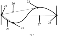
- sensors 21-24 are shown attached to the patient's spine 28 and they may be used to calculate, via trigonometry using the distances between the sensors, a 3D image and measurement ( Fig. 4 ) of the state of the spine, which can be used to calculate where and to what extent the spine is curved. Regular measurements will determine whether an increase in curvature had occurred during exercise or other activity.
- a 3D model can be created and oriented correctly using the accelerometers' data to define which way up the model is in space.
- Fig. 3 shows the distances computed between sensors, e.g. 25 between 24 and 23, 26 between 24 and 22 and 27 between 24 and 21. More sensors 21-24 may be used to identify which particular disc(s) is(are) causing the problem(s).
- the sound used could be ultrasound, instead of audible sound, so that it did not disturb the patient when asleep and the signals could be sent out periodically with either the absolute values of ⁇ t recorded or the differences ( ⁇ t H - ⁇ t V ).
- the receiving sensor could directly compute the ( ⁇ t H - ⁇ t V ) ⁇ 332 values and record the time of the measurement for subsequent downloading or display.
- spinal extension has been used as the example here, the principle has other applications, e.g. to assess problems with hip, knee, ankle or foot joints between when a person is standing and lying down or with shoulder, elbow, wrist or hand joints in a person, who repeatedly has to lift heavy weights above his head, etc.
Landscapes
- Health & Medical Sciences (AREA)
- Life Sciences & Earth Sciences (AREA)
- Physics & Mathematics (AREA)
- Heart & Thoracic Surgery (AREA)
- Molecular Biology (AREA)
- Veterinary Medicine (AREA)
- Biophysics (AREA)
- Pathology (AREA)
- Engineering & Computer Science (AREA)
- Biomedical Technology (AREA)
- Public Health (AREA)
- Medical Informatics (AREA)
- General Health & Medical Sciences (AREA)
- Surgery (AREA)
- Animal Behavior & Ethology (AREA)
- Oral & Maxillofacial Surgery (AREA)
- Dentistry (AREA)
- Physiology (AREA)
- Physical Education & Sports Medicine (AREA)
- Orthopedic Medicine & Surgery (AREA)
- Rheumatology (AREA)
- Geometry (AREA)
- Measurement Of The Respiration, Hearing Ability, Form, And Blood Characteristics Of Living Organisms (AREA)
Claims (4)
- Procédé de goniométrie permettant d'obtenir des données concernant la plage de mouvement dans une articulation d'un patient, destiné à être utilisé dans le traitement et les soins d'êtres vivants, le système de procédé comprenant :i) la fourniture d'un premier (11) et d'un second (13) dispositif de détection électronique, chacun pouvant être fixé à une partie du corps d'un patient, et comprenant chacun :a) un moyen de fournir de l'énergie électrique ;b) en tant que capteur,
au moins l'un d'un accéléromètre, d'un magnétomètre et/ou d'un gyroscope ; etc) une mémoire pour enregistrer des informations relatives à un paramètre mesuré et les stocker, ou pour calculer une lecture nette et la stocker, en vue du téléchargement et/ou de la transmission à une unité de réception distincte ; etii) la fourniture d'une unité de réception adaptée pour recevoir des lectures en provenance des dispositifs de détection (11, 13) ;iii) la fourniture de moyens de traitement pour rassembler, analyser et afficher les résultats de l'analyse des informations enregistrées ou de la lecture nette à partir des capteurs ;le procédé comprenant les étapes supplémentaires de :fixation du premier dispositif de détection (11) à une partie du corps du patient sur un premier côté de l'articulation ;fixation du second dispositif de détection (13) à une partie du corps du patient sur un second côté de l'articulation ;manipulation de l'appendice du patient, les moyens de traitement étant utilisés pour déterminer le mouvement relatif entre les capteurs afin de montrer le mouvement des membres ou des articulations ;caractérisé en ce que les dispositifs de détection électroniques (11, 13)comprennent en outre un capteur de forcepour surveiller et enregistrer la quantité de force appliquée au membre d'un patient lorsque le membre est manipulé. - Procédé selon la revendication 1, caractérisé en ce qu'une mesure objective de l'angle de déviation entre les deux capteurs (11, 13) est déterminée par les moyens de traitement en surveillant l'angle , ou les angles, de déviation entre le premier dispositif de détection électronique (11) et le second dispositif de détection électronique (13) et à partir de la surveillance de toute rotation entre les deux.
- Procédé selon la revendication 1 ou la revendication 2, caractérisé en ce que le procédé comprend en outre l'étape de comparaison de jusqu'où une articulation peut être déplacée lorsqu'une quantité prédéfinie de force est appliquée avec une mesure précédente du mouvement de l'articulation pour une quantité donnée de force.
- Procédé selon une quelconque revendication précédente, caractérisé en ce que les dispositifs de détection électroniques (11, 13) comprennent chacun un accéléromètre et un gyroscope et/ou un magnétomètre.
Applications Claiming Priority (4)
| Application Number | Priority Date | Filing Date | Title |
|---|---|---|---|
| GB1506810.9A GB2537644A (en) | 2015-04-22 | 2015-04-22 | Electronic equipment for the treatment and care of living beings |
| GBGB1604925.6A GB201604925D0 (en) | 2015-04-22 | 2016-03-23 | Electronic equipment for the treatment and care of living beings |
| GB1606860.3A GB2537754B (en) | 2015-04-22 | 2016-04-20 | Electronic equipment for the treatment and care of living beings |
| PCT/GB2016/051123 WO2016170354A2 (fr) | 2015-04-22 | 2016-04-22 | Équipement électronique pour le traitement et le soin d'êtres vivants |
Publications (3)
| Publication Number | Publication Date |
|---|---|
| EP3285646A2 EP3285646A2 (fr) | 2018-02-28 |
| EP3285646C0 EP3285646C0 (fr) | 2024-09-18 |
| EP3285646B1 true EP3285646B1 (fr) | 2024-09-18 |
Family
ID=53298972
Family Applications (1)
| Application Number | Title | Priority Date | Filing Date |
|---|---|---|---|
| EP16723808.8A Active EP3285646B1 (fr) | 2015-04-22 | 2016-04-22 | Équipement électronique pour le traitement et le soin d'êtres vivants |
Country Status (4)
| Country | Link |
|---|---|
| US (2) | US20180110446A1 (fr) |
| EP (1) | EP3285646B1 (fr) |
| GB (3) | GB2537644A (fr) |
| WO (1) | WO2016170354A2 (fr) |
Families Citing this family (4)
| Publication number | Priority date | Publication date | Assignee | Title |
|---|---|---|---|---|
| GB2537644A (en) * | 2015-04-22 | 2016-10-26 | Tintro Ltd | Electronic equipment for the treatment and care of living beings |
| PL423224A1 (pl) * | 2017-10-21 | 2019-04-23 | Rsq Tech Spolka Z Ograniczona Odpowiedzialnoscia | Sposób mierzenia i odwzorowywania ruchu ciała zwłaszcza przy leczeniu i diagnostyce ortopedycznej |
| CN110801231A (zh) * | 2019-10-14 | 2020-02-18 | 西安理工大学 | 一种针对膝关节炎患者关节功能的交互式评价方法 |
| CN113379888B (zh) * | 2021-01-18 | 2023-08-22 | 兰州理工大学 | 一种基于二维图片的人体三维模型重建及参数测量方法 |
Citations (5)
| Publication number | Priority date | Publication date | Assignee | Title |
|---|---|---|---|---|
| US20030163287A1 (en) * | 2000-12-15 | 2003-08-28 | Vock Curtis A. | Movement and event systems and associated methods related applications |
| US20070250286A1 (en) * | 2003-07-01 | 2007-10-25 | Queensland University Of Technology | Motion Monitoring and Analysis System |
| WO2010088696A1 (fr) * | 2009-02-02 | 2010-08-05 | Mohamed Rashwan Mahfouz | Système diagnostic non invasif |
| US20110213275A1 (en) * | 2008-06-27 | 2011-09-01 | Bort Gmbh | Device for determining the stability of a knee joint |
| US20130211259A1 (en) * | 2009-02-02 | 2013-08-15 | Jointvue, Llc | Determination of joint condition based on vibration analysis |
Family Cites Families (33)
| Publication number | Priority date | Publication date | Assignee | Title |
|---|---|---|---|---|
| US3972038A (en) * | 1975-03-28 | 1976-07-27 | Nasa | Accelerometer telemetry system |
| US5826578A (en) * | 1994-05-26 | 1998-10-27 | Curchod; Donald B. | Motion measurement apparatus |
| US6493652B1 (en) * | 1997-10-02 | 2002-12-10 | Personal Electronic Devices, Inc. | Monitoring activity of a user in locomotion on foot |
| US6298314B1 (en) * | 1997-10-02 | 2001-10-02 | Personal Electronic Devices, Inc. | Detecting the starting and stopping of movement of a person on foot |
| US6898550B1 (en) * | 1997-10-02 | 2005-05-24 | Fitsense Technology, Inc. | Monitoring activity of a user in locomotion on foot |
| US6018705A (en) * | 1997-10-02 | 2000-01-25 | Personal Electronic Devices, Inc. | Measuring foot contact time and foot loft time of a person in locomotion |
| US6611789B1 (en) * | 1997-10-02 | 2003-08-26 | Personal Electric Devices, Inc. | Monitoring activity of a user in locomotion on foot |
| US6882955B1 (en) * | 1997-10-02 | 2005-04-19 | Fitsense Technology, Inc. | Monitoring activity of a user in locomotion on foot |
| US6699199B2 (en) * | 2000-04-18 | 2004-03-02 | Massachusetts Institute Of Technology | Photoplethysmograph signal-to-noise line enhancement |
| US6826509B2 (en) * | 2000-10-11 | 2004-11-30 | Riddell, Inc. | System and method for measuring the linear and rotational acceleration of a body part |
| US8797165B2 (en) * | 2000-10-11 | 2014-08-05 | Riddell, Inc. | System for monitoring a physiological parameter of players engaged in a sporting activity |
| US7526389B2 (en) * | 2000-10-11 | 2009-04-28 | Riddell, Inc. | Power management of a system for measuring the acceleration of a body part |
| US7554549B2 (en) * | 2004-10-01 | 2009-06-30 | Sony Corporation | System and method for tracking facial muscle and eye motion for computer graphics animation |
| US7478009B2 (en) * | 2005-07-29 | 2009-01-13 | Wake Forest University Health Sciences | Apparatus and method for evaluating a hypertonic condition |
| US8333722B2 (en) * | 2005-10-24 | 2012-12-18 | Paul Ewing | Communications during rehabilitation |
| US7602301B1 (en) * | 2006-01-09 | 2009-10-13 | Applied Technology Holdings, Inc. | Apparatus, systems, and methods for gathering and processing biometric and biomechanical data |
| US7610166B1 (en) * | 2006-07-21 | 2009-10-27 | James Solinsky | Geolocation system and method for determining mammal locomotion movement |
| CN101522101B (zh) * | 2006-10-11 | 2012-02-29 | 皇家飞利浦电子股份有限公司 | 肢体运动监视系统 |
| WO2008102291A2 (fr) * | 2007-02-20 | 2008-08-28 | Philips Intellectual Property & Standards Gmbh | Procédé et système pour identifier un sujet |
| US9408575B2 (en) * | 2009-04-29 | 2016-08-09 | Bio-Signal Group Corp. | EEG kit |
| JP5302289B2 (ja) * | 2009-12-18 | 2013-10-02 | 韓國電子通信研究院 | 携帯型消費熱量測定装置 |
| US8888720B2 (en) * | 2010-04-02 | 2014-11-18 | Stanford P. Hudson | Great toe dorsiflexion detection |
| CN102551685B (zh) * | 2010-12-30 | 2015-04-01 | 世意法(北京)半导体研发有限责任公司 | 对象监视器 |
| US8666738B2 (en) * | 2011-05-24 | 2014-03-04 | Alcatel Lucent | Biometric-sensor assembly, such as for acoustic reflectometry of the vocal tract |
| WO2013123263A1 (fr) * | 2012-02-14 | 2013-08-22 | The Regents Of The University Of California | Appareil et procédé pour quantifier la stabilité du genou |
| US9891718B2 (en) * | 2015-04-22 | 2018-02-13 | Medibotics Llc | Devices for measuring finger motion and recognizing hand gestures |
| US9254099B2 (en) * | 2013-05-23 | 2016-02-09 | Medibotics Llc | Smart watch and food-imaging member for monitoring food consumption |
| DE102012019859B4 (de) * | 2012-10-10 | 2014-09-04 | Wolfgang Beyer | System und Verfahren zur mobilen Datenverarbeitung sowie Voreinstellung der Trainingsgeräte im Fitnessbereich und bei der medizinischen Rehabitation |
| EP2916732A4 (fr) * | 2012-11-09 | 2016-07-06 | Dorsavi Pty Ltd | Procédé et appareil pour surveiller la déviation d'un membre |
| US20150045700A1 (en) * | 2013-08-09 | 2015-02-12 | University Of Washington Through Its Center For Commercialization | Patient activity monitoring systems and associated methods |
| US10215568B2 (en) * | 2015-01-30 | 2019-02-26 | Vision Service Plan | Systems and methods for tracking motion, performance, and other data for an individual such as a winter sports athlete |
| US20160220175A1 (en) * | 2015-02-03 | 2016-08-04 | The Board Of Trustees Of The Leland Stanford Junior University | Apparatus and method for range of motion tracking with integrated reporting |
| GB2537644A (en) * | 2015-04-22 | 2016-10-26 | Tintro Ltd | Electronic equipment for the treatment and care of living beings |
-
2015
- 2015-04-22 GB GB1506810.9A patent/GB2537644A/en not_active Withdrawn
-
2016
- 2016-03-23 GB GBGB1604925.6A patent/GB201604925D0/en not_active Ceased
- 2016-04-20 GB GB1606860.3A patent/GB2537754B/en active Active
- 2016-04-22 EP EP16723808.8A patent/EP3285646B1/fr active Active
- 2016-04-22 WO PCT/GB2016/051123 patent/WO2016170354A2/fr not_active Ceased
- 2016-04-22 US US15/568,528 patent/US20180110446A1/en not_active Abandoned
-
2020
- 2020-05-13 US US15/930,862 patent/US12453489B2/en active Active
Patent Citations (5)
| Publication number | Priority date | Publication date | Assignee | Title |
|---|---|---|---|---|
| US20030163287A1 (en) * | 2000-12-15 | 2003-08-28 | Vock Curtis A. | Movement and event systems and associated methods related applications |
| US20070250286A1 (en) * | 2003-07-01 | 2007-10-25 | Queensland University Of Technology | Motion Monitoring and Analysis System |
| US20110213275A1 (en) * | 2008-06-27 | 2011-09-01 | Bort Gmbh | Device for determining the stability of a knee joint |
| WO2010088696A1 (fr) * | 2009-02-02 | 2010-08-05 | Mohamed Rashwan Mahfouz | Système diagnostic non invasif |
| US20130211259A1 (en) * | 2009-02-02 | 2013-08-15 | Jointvue, Llc | Determination of joint condition based on vibration analysis |
Also Published As
| Publication number | Publication date |
|---|---|
| GB201604925D0 (en) | 2016-05-04 |
| GB2537754B (en) | 2021-11-17 |
| GB2537754A (en) | 2016-10-26 |
| EP3285646A2 (fr) | 2018-02-28 |
| US20180110446A1 (en) | 2018-04-26 |
| GB201506810D0 (en) | 2015-06-03 |
| EP3285646C0 (fr) | 2024-09-18 |
| US20200315497A1 (en) | 2020-10-08 |
| US12453489B2 (en) | 2025-10-28 |
| WO2016170354A2 (fr) | 2016-10-27 |
| WO2016170354A3 (fr) | 2016-12-01 |
| GB2537644A (en) | 2016-10-26 |
Similar Documents
| Publication | Publication Date | Title |
|---|---|---|
| US12453489B2 (en) | Electronic equipment for the treatment and care of living beings | |
| Papi et al. | Use of wearable technology for performance assessment: A validation study | |
| US11679300B2 (en) | Systems and methods for real-time data quantification, acquisition, analysis, and feedback | |
| AU2017386412B2 (en) | Systems and methods for real-time data quantification, acquisition, analysis, and feedback | |
| Aminian et al. | Capturing human motion using body‐fixed sensors: outdoor measurement and clinical applications | |
| CN104159644B (zh) | 分析高尔夫挥杆的装置和方法 | |
| US20050126026A1 (en) | Posture and body movement measuring system | |
| WO2011163367A1 (fr) | Procédé de surveillance de mouvement de corps humain | |
| AU5089900A (en) | Rehabilitation device | |
| JP6837484B2 (ja) | 運動をデジタル化し評価する装置 | |
| US11179065B2 (en) | Systems, devices, and methods for determining an overall motion and flexibility envelope | |
| US20230012734A1 (en) | A wearable device and associated methods and systems | |
| Watanabe et al. | Tests of wireless wearable sensor system in joint angle measurement of lower limbs | |
| WO2017218907A1 (fr) | Systèmes, dispositifs et procédés pour déterminer une enveloppe de force globale. | |
| Nwanna | Validation of an Accelerometry based method of human gait analysis | |
| Paladugu et al. | A sensor cluster to monitor body kinematics | |
| WO2020007802A1 (fr) | Système de détection et de surveillance cinématique de mouvements corporels dans l'eau, et procédé associé | |
| RU222339U1 (ru) | Устройство для анализа движений нижних конечностей человека | |
| GB2377157A (en) | Garment with pockets for holding monitoring devices | |
| Carey et al. | Development of a wearable motion analysis system for evaluation and rehabilitation of mild traumatic brain injury (mTBI) | |
| US20240374191A1 (en) | Wearable Muscle Tissue Tensiometer with Bilateral Work and Power Measurement | |
| Busa | CLINICIAN'S CORNER: The Use of Accelerometers to Assess Human Locomotion | |
| Ohtaki et al. | Gait characterization of pre-and postoperative patients with lumbar spinal stenosis utilizing a body-mounted inertial measurement unit | |
| Nguyen | IMU-Integrated'Smart'Knee Brace Validation Using Optoelectronic Motion Capture During Treadmill Walking | |
| Hanyu | Effect of fatigue on lower extremity symmetry in recreational runners |
Legal Events
| Date | Code | Title | Description |
|---|---|---|---|
| STAA | Information on the status of an ep patent application or granted ep patent |
Free format text: STATUS: THE INTERNATIONAL PUBLICATION HAS BEEN MADE |
|
| PUAI | Public reference made under article 153(3) epc to a published international application that has entered the european phase |
Free format text: ORIGINAL CODE: 0009012 |
|
| STAA | Information on the status of an ep patent application or granted ep patent |
Free format text: STATUS: REQUEST FOR EXAMINATION WAS MADE |
|
| 17P | Request for examination filed |
Effective date: 20171120 |
|
| AK | Designated contracting states |
Kind code of ref document: A2 Designated state(s): AL AT BE BG CH CY CZ DE DK EE ES FI FR GB GR HR HU IE IS IT LI LT LU LV MC MK MT NL NO PL PT RO RS SE SI SK SM TR |
|
| AX | Request for extension of the european patent |
Extension state: BA ME |
|
| DAV | Request for validation of the european patent (deleted) | ||
| DAX | Request for extension of the european patent (deleted) | ||
| STAA | Information on the status of an ep patent application or granted ep patent |
Free format text: STATUS: EXAMINATION IS IN PROGRESS |
|
| PUAG | Search results despatched under rule 164(2) epc together with communication from examining division |
Free format text: ORIGINAL CODE: 0009017 |
|
| 17Q | First examination report despatched |
Effective date: 20190801 |
|
| B565 | Issuance of search results under rule 164(2) epc |
Effective date: 20190801 |
|
| RIC1 | Information provided on ipc code assigned before grant |
Ipc: A61B 5/00 20060101ALI20190729BHEP Ipc: A61B 5/11 20060101AFI20190729BHEP |
|
| P01 | Opt-out of the competence of the unified patent court (upc) registered |
Effective date: 20230525 |
|
| GRAP | Despatch of communication of intention to grant a patent |
Free format text: ORIGINAL CODE: EPIDOSNIGR1 |
|
| STAA | Information on the status of an ep patent application or granted ep patent |
Free format text: STATUS: GRANT OF PATENT IS INTENDED |
|
| INTG | Intention to grant announced |
Effective date: 20240416 |
|
| GRAS | Grant fee paid |
Free format text: ORIGINAL CODE: EPIDOSNIGR3 |
|
| GRAA | (expected) grant |
Free format text: ORIGINAL CODE: 0009210 |
|
| STAA | Information on the status of an ep patent application or granted ep patent |
Free format text: STATUS: THE PATENT HAS BEEN GRANTED |
|
| AK | Designated contracting states |
Kind code of ref document: B1 Designated state(s): AL AT BE BG CH CY CZ DE DK EE ES FI FR GB GR HR HU IE IS IT LI LT LU LV MC MK MT NL NO PL PT RO RS SE SI SK SM TR |
|
| REG | Reference to a national code |
Ref country code: GB Ref legal event code: FG4D |
|
| REG | Reference to a national code |
Ref country code: CH Ref legal event code: EP |
|
| REG | Reference to a national code |
Ref country code: DE Ref legal event code: R096 Ref document number: 602016089444 Country of ref document: DE |
|
| REG | Reference to a national code |
Ref country code: IE Ref legal event code: FG4D |
|
| U01 | Request for unitary effect filed |
Effective date: 20241018 |
|
| P04 | Withdrawal of opt-out of the competence of the unified patent court (upc) registered |
Free format text: CASE NUMBER: APP_59069/2024 Effective date: 20241030 |
|
| U07 | Unitary effect registered |
Designated state(s): AT BE BG DE DK EE FI FR IT LT LU LV MT NL PT RO SE SI Effective date: 20241104 |
|
| PG25 | Lapsed in a contracting state [announced via postgrant information from national office to epo] |
Ref country code: NO Free format text: LAPSE BECAUSE OF FAILURE TO SUBMIT A TRANSLATION OF THE DESCRIPTION OR TO PAY THE FEE WITHIN THE PRESCRIBED TIME-LIMIT Effective date: 20241218 |
|
| PG25 | Lapsed in a contracting state [announced via postgrant information from national office to epo] |
Ref country code: GR Free format text: LAPSE BECAUSE OF FAILURE TO SUBMIT A TRANSLATION OF THE DESCRIPTION OR TO PAY THE FEE WITHIN THE PRESCRIBED TIME-LIMIT Effective date: 20241219 |
|
| PG25 | Lapsed in a contracting state [announced via postgrant information from national office to epo] |
Ref country code: HR Free format text: LAPSE BECAUSE OF FAILURE TO SUBMIT A TRANSLATION OF THE DESCRIPTION OR TO PAY THE FEE WITHIN THE PRESCRIBED TIME-LIMIT Effective date: 20240918 |
|
| PG25 | Lapsed in a contracting state [announced via postgrant information from national office to epo] |
Ref country code: RS Free format text: LAPSE BECAUSE OF FAILURE TO SUBMIT A TRANSLATION OF THE DESCRIPTION OR TO PAY THE FEE WITHIN THE PRESCRIBED TIME-LIMIT Effective date: 20241218 |
|
| PG25 | Lapsed in a contracting state [announced via postgrant information from national office to epo] |
Ref country code: RS Free format text: LAPSE BECAUSE OF FAILURE TO SUBMIT A TRANSLATION OF THE DESCRIPTION OR TO PAY THE FEE WITHIN THE PRESCRIBED TIME-LIMIT Effective date: 20241218 Ref country code: NO Free format text: LAPSE BECAUSE OF FAILURE TO SUBMIT A TRANSLATION OF THE DESCRIPTION OR TO PAY THE FEE WITHIN THE PRESCRIBED TIME-LIMIT Effective date: 20241218 Ref country code: HR Free format text: LAPSE BECAUSE OF FAILURE TO SUBMIT A TRANSLATION OF THE DESCRIPTION OR TO PAY THE FEE WITHIN THE PRESCRIBED TIME-LIMIT Effective date: 20240918 Ref country code: GR Free format text: LAPSE BECAUSE OF FAILURE TO SUBMIT A TRANSLATION OF THE DESCRIPTION OR TO PAY THE FEE WITHIN THE PRESCRIBED TIME-LIMIT Effective date: 20241219 |
|
| PG25 | Lapsed in a contracting state [announced via postgrant information from national office to epo] |
Ref country code: IS Free format text: LAPSE BECAUSE OF FAILURE TO SUBMIT A TRANSLATION OF THE DESCRIPTION OR TO PAY THE FEE WITHIN THE PRESCRIBED TIME-LIMIT Effective date: 20250118 |
|
| PG25 | Lapsed in a contracting state [announced via postgrant information from national office to epo] |
Ref country code: SM Free format text: LAPSE BECAUSE OF FAILURE TO SUBMIT A TRANSLATION OF THE DESCRIPTION OR TO PAY THE FEE WITHIN THE PRESCRIBED TIME-LIMIT Effective date: 20240918 |
|
| PG25 | Lapsed in a contracting state [announced via postgrant information from national office to epo] |
Ref country code: ES Free format text: LAPSE BECAUSE OF FAILURE TO SUBMIT A TRANSLATION OF THE DESCRIPTION OR TO PAY THE FEE WITHIN THE PRESCRIBED TIME-LIMIT Effective date: 20240918 |
|
| PG25 | Lapsed in a contracting state [announced via postgrant information from national office to epo] |
Ref country code: PL Free format text: LAPSE BECAUSE OF FAILURE TO SUBMIT A TRANSLATION OF THE DESCRIPTION OR TO PAY THE FEE WITHIN THE PRESCRIBED TIME-LIMIT Effective date: 20240918 Ref country code: CZ Free format text: LAPSE BECAUSE OF FAILURE TO SUBMIT A TRANSLATION OF THE DESCRIPTION OR TO PAY THE FEE WITHIN THE PRESCRIBED TIME-LIMIT Effective date: 20240918 |
|
| PG25 | Lapsed in a contracting state [announced via postgrant information from national office to epo] |
Ref country code: SK Free format text: LAPSE BECAUSE OF FAILURE TO SUBMIT A TRANSLATION OF THE DESCRIPTION OR TO PAY THE FEE WITHIN THE PRESCRIBED TIME-LIMIT Effective date: 20240918 |
|
| U20 | Renewal fee for the european patent with unitary effect paid |
Year of fee payment: 10 Effective date: 20250430 |
|
| PLBE | No opposition filed within time limit |
Free format text: ORIGINAL CODE: 0009261 |
|
| STAA | Information on the status of an ep patent application or granted ep patent |
Free format text: STATUS: NO OPPOSITION FILED WITHIN TIME LIMIT |
|
| 26N | No opposition filed |
Effective date: 20250619 |
|
| REG | Reference to a national code |
Ref country code: CH Ref legal event code: H13 Free format text: ST27 STATUS EVENT CODE: U-0-0-H10-H13 (AS PROVIDED BY THE NATIONAL OFFICE) Effective date: 20251125 |
|
| PG25 | Lapsed in a contracting state [announced via postgrant information from national office to epo] |
Ref country code: MC Free format text: LAPSE BECAUSE OF FAILURE TO SUBMIT A TRANSLATION OF THE DESCRIPTION OR TO PAY THE FEE WITHIN THE PRESCRIBED TIME-LIMIT Effective date: 20240918 |
|
| PG25 | Lapsed in a contracting state [announced via postgrant information from national office to epo] |
Ref country code: CH Free format text: LAPSE BECAUSE OF NON-PAYMENT OF DUE FEES Effective date: 20250430 |
|
| PGFP | Annual fee paid to national office [announced via postgrant information from national office to epo] |
Ref country code: GB Payment date: 20260320 Year of fee payment: 11 |
|
| PG25 | Lapsed in a contracting state [announced via postgrant information from national office to epo] |
Ref country code: IE Free format text: LAPSE BECAUSE OF NON-PAYMENT OF DUE FEES Effective date: 20250422 |