EP3285671B1 - Tplo-knochenplatte - Google Patents
Tplo-knochenplatte Download PDFInfo
- Publication number
- EP3285671B1 EP3285671B1 EP16783714.5A EP16783714A EP3285671B1 EP 3285671 B1 EP3285671 B1 EP 3285671B1 EP 16783714 A EP16783714 A EP 16783714A EP 3285671 B1 EP3285671 B1 EP 3285671B1
- Authority
- EP
- European Patent Office
- Prior art keywords
- head portion
- bone plate
- elongated shaft
- bone
- shaft
- Prior art date
- Legal status (The legal status is an assumption and is not a legal conclusion. Google has not performed a legal analysis and makes no representation as to the accuracy of the status listed.)
- Active
Links
Images







Classifications
-
- A—HUMAN NECESSITIES
- A61—MEDICAL OR VETERINARY SCIENCE; HYGIENE
- A61B—DIAGNOSIS; SURGERY; IDENTIFICATION
- A61B17/00—Surgical instruments, devices or methods
- A61B17/56—Surgical instruments or methods for treatment of bones or joints; Devices specially adapted therefor
- A61B17/58—Surgical instruments or methods for treatment of bones or joints; Devices specially adapted therefor for osteosynthesis, e.g. bone plates, screws or setting implements
- A61B17/68—Internal fixation devices, including fasteners and spinal fixators, even if a part thereof projects from the skin
- A61B17/80—Cortical plates, i.e. bone plates; Instruments for holding or positioning cortical plates, or for compressing bones attached to cortical plates
- A61B17/8061—Cortical plates, i.e. bone plates; Instruments for holding or positioning cortical plates, or for compressing bones attached to cortical plates specially adapted for particular bones
-
- A—HUMAN NECESSITIES
- A61—MEDICAL OR VETERINARY SCIENCE; HYGIENE
- A61B—DIAGNOSIS; SURGERY; IDENTIFICATION
- A61B17/00—Surgical instruments, devices or methods
- A61B17/16—Instruments for performing osteoclasis; Drills or chisels for bones; Trepans
- A61B17/17—Guides or aligning means for drills, mills, pins or wires
- A61B17/1728—Guides or aligning means for drills, mills, pins or wires for holes for bone plates or plate screws
-
- A—HUMAN NECESSITIES
- A61—MEDICAL OR VETERINARY SCIENCE; HYGIENE
- A61B—DIAGNOSIS; SURGERY; IDENTIFICATION
- A61B17/00—Surgical instruments, devices or methods
- A61B17/16—Instruments for performing osteoclasis; Drills or chisels for bones; Trepans
- A61B17/17—Guides or aligning means for drills, mills, pins or wires
- A61B17/1739—Guides or aligning means for drills, mills, pins or wires specially adapted for particular parts of the body
-
- A—HUMAN NECESSITIES
- A61—MEDICAL OR VETERINARY SCIENCE; HYGIENE
- A61B—DIAGNOSIS; SURGERY; IDENTIFICATION
- A61B17/00—Surgical instruments, devices or methods
- A61B17/56—Surgical instruments or methods for treatment of bones or joints; Devices specially adapted therefor
- A61B17/58—Surgical instruments or methods for treatment of bones or joints; Devices specially adapted therefor for osteosynthesis, e.g. bone plates, screws or setting implements
- A61B17/68—Internal fixation devices, including fasteners and spinal fixators, even if a part thereof projects from the skin
- A61B17/80—Cortical plates, i.e. bone plates; Instruments for holding or positioning cortical plates, or for compressing bones attached to cortical plates
- A61B17/8052—Cortical plates, i.e. bone plates; Instruments for holding or positioning cortical plates, or for compressing bones attached to cortical plates immobilised relative to screws by interlocking form of the heads and plate holes, e.g. conical or threaded
Definitions
- This invention primarily relates to a bone plate dimension for securing the rotated cut segment of an upper tibia to the lower portion of the tibia as part of a tibial leveling osteotomy procedure for an animal.
- TPLO tibial plateau leveling osteotomy
- CCL cranial cruciate ligament
- the result can also be bone plates which do not properly secure the two tibia sections together, bone screws which do not properly hold (shorter bone screws may have to be used) and/or which extend into the stifle (knee) joint causing damage to the articular and periarticular surfaces possibly leading to osteoarthritis.
- Other TPLO plates have a head shape which interfere with features of the cut, rotated tibial plateau.
- U.S. Pat. App. Pub. No. 2010/0030276A1 teaches a periarticular bone plate with biplanar offset head meter.
- U.S. Pat. App. Pub. No. 2007/0233106A1 teaches a tibial plateau leveling osteotomy plate.
- U.S. Pat. App. Pub. No. 20140336712A1 teaches an orthopedic plate.
- U.S. Pat. App. Pub. No. 2012/007852A1 teaches a targeting guide with a radiopaque marker to facilitate positioning a bone plate on bone.
- U.S. Pat. App. Pub. No. 2002/0156474A1 teaches a polyaxial locking plate.
- CN203953787 teaches a latter tibial post lock plate.
- U.S. Pat. App. Pub. No. 2009/0018588A1 teaches an orthopedic screw fastener system.
- U.S. Pat. App. Pub. No. 2011/0301655A1
- the present invention relates to a device as claimed hereafter.
- Preferred embodiments of the invention are set forth in the dependent claims.
- the new TPLO plate is anatomically pre-contoured so the elongated shaft portion is aligned with the long axis of the tibia to allow for more bone purchase by screws (e.g., longer screws can be used) and greater stiffness while at the same time providing a better fit of the head portion to the rotated portion of the tibia.
- the preferred bone plate includes an elongated shaft with a top surface and bottom bone contacting surface between opposing sides of the bone plate elongated shaft. Screw holes in the elongated shaft extend from the top surface to the bottom bone contacting surface for securing the elongated shaft to the lower portion of the tibia.
- a head portion is pre-bent with respect to the elongated shaft and with a top surface and a bottom bone contacting surface between sidewalls of the bone plate head portion.
- Screw holes in the head portion extend from the top surface to the bottom bone contacting surface thereof for securing the head portion to, the rotated cut segment of the upper tibia.
- the elongated shaft has a centerline and the pre-bent head portion has a centerline angled with respect to the centerline of the elongated shaft in order to dispose the elongated shaft collinear or approximately collinear with respect to the lower portion of the tibia and to better fit the head portion to the rotated cut segment of the upper tibia.
- the angle between the centerline of the elongated shaft and the centerline of the head portion is 15° - 40°, preferably 25°-30°.
- the angle between the centerline of the elongated shaft and the centerline of the head portion is smaller for larger size bone plates and larger for smaller size bone plates.
- Different size bone plates may have a head portion with a cloverleaf shape and other size bone plates have a head portion with a crescent shape.
- the leg portion lies in a first plane and the head portion is bent upwardly and lies in the second plane angled with respect to the first plane.
- the bone plate head portion may have a bottom bone contacting surface which is anatomically contoured to match the contour of the rotated cut tibia segment.
- the elongated shaft opposing sides have spaced curved notches for further bending the head portion relative to the elongated shaft to vary the angle between the centerline of the head portion and the centerline of the elongated shaft during a TPLO procedure.
- Spaced curved notches are typically disposed between adjacent screw holes in the elongated shaft.
- the elongated shaft bottom bone contacting surface may include spaced transverse grooves to reduce contact between the elongated shaft bottom surface and the lower portion of the tibia.
- the bone plate screw holes in the elongated shaft and/or head portion may include a central opening, a plurality of bores spaced around said central opening and intersection surfaces formed from a common intersection of the central opening and adjacent bores. Screw holes may further include a countersink above said intersection surfaces for a non-locking screw.
- the bone plate may be made of a titanium alloy.
- the bone plate may also include one or more k-wire holes.
- the shaft may have a beveled distal end.
- the head portion may have a beveled proximal end.
- the bone plate may further include a contoured registration mark on the top surface of the plate proximate the transition to assist a surgeon in placing the bone plate on the rotated cut segment of the upper tibia.
- the bone plate may further include a drill guide plate configured the same as the bone plate and including top surface drill guide ports oriented to overlie the screw holes in the bone plate.
- each plate there is a transition between the elongated shaft and head portion including opposing concave sidewalls.
- the elongated shaft has a centerline and the head portion has a centerline angled with respect to the centerline of the elongated shaft to dispose the elongated shaft collinear or approximately collinear with respect to the lower portion of the tibia and to fit the head portion to the rotated cut segment of the upper tibia.
- the angle between the centerline of the elongated shaft and the centerline of the head portion is different for different size bone plates in the set.
- Figs. 1-5 show various prior art TPLO bone plates which may not be optimized or specifically tailored for a TPLO procedure where the cut is made fairly high on the upper tibia. Some prior TPLO bone plates may require that the lower leg section or shaft portion be angled with respect to the lower tibia. In some prior art TPLO plates, the bone plate head section is not optimized or tailored for the now smaller rotated cut upper tibia segment. Other possible limitations associated with some prior TPLO plates are discussed above with respect to the Background section hereof.
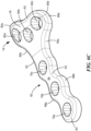
- Fig. 6A-6D show an example of a new TPLO bone plate 60 with elongated shaft or leg 62 having top surface 64, bottom surface 66, and opposing side surfaces 68a and 68b.
- Shaft 62 in this particular example includes three screw holes 70a, 70b, and 70c for securing shaft 62 to the lower portion of the tibia as shown in Fig. 14 .
- Head portion 74 extends from shaft 62 as shown and has a top surface 76 and bottom surface 78 between opposing sides 80a and 80b. Screw holes 82a, 82b, and 82c in head portion 74 are designed to secure head portion 74 to the rotated cut segment of the upper tibia and the leg portion or shaft is secured to the lower portion of the tibia.
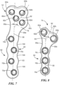
- Fig. 6A As shown in Fig. 6A , at the transition 93 between elongated shaft 62 and head portion 74 there are opposing concave sidewalls 95a and 95b between the top of shaft 62 and the bottom of outer lobes 83a and 83b of head portion 74. Both transition sidewalls are angled in the same direction (to the right of Fig. 6A ) with respect to the centerline 90 of shaft 62. This pre-bend of the head portion optimizes placement of the head portion on the cut upper tibia. After the reduced width transition section due to concave sidewalls 95a and 95b, the bent head portion generally flairs to a wider top end shown in Fig. 6 as a crescent style head. A cloverleaf head design is also possible, see Fig. 7 and head portion 74'. Another head style bone plate is shown in Fig. 8 .
- the head portion 74, Fig. 6 is thus angled with respect to the shaft (to the right or left depending on the leg undergoing a TPLO procedure).
- This pre-bend in the XY plane of the TPLO plate helps align the elongated shaft portion 62 collinear with the lower tibia especially when the cut is made fairly high on the upper tibia.
- longer bone screws can be used and/or there is better contact between the elongated shaft portion and the lower portion of the tibia for greater strength, holding power, and stiffness provided by the bone plate.
- the bend in the XY plane of the TPLO plate also optimizes placement of the head portion 74 on the cut rotated upper tibia segment for easier and more effective attachment thereto.
- shaft 62 has a centerline 90 in this particular example, head portion 74 has centerline 92 and there is angle ⁇ between shaft centerline 90 and head portion centerline 92.
- ⁇ may range from 15° - 40°, preferably from 25° to 30° and may be different depending on the size of the bone plate.
- Head 74 may also be shaped differently depending on the size of the bone plate.
- Fig. 6 shows a crescent style head but other head shapes such as cloverleaf shapes may be used.
- a crescent style has outer lobes 83a and 83b around the outer holes 82a and 82c with a dip 81 between the two outer lobes at the centerline 92 of head portion 74.
- a cloverleaf design, Fig. 7 has another lobe 83b between the two outer lobes 83a, 83c generally located at the head portion centerline.
- these plates are sold as a set.
- Table 1 includes several types of plates available in the set. TABLE 1 Size ⁇ Blade Size Head Style Length Head Width 3.5 mm broad 25° 27-30 mm Cloverleaf (four holes) 82 mm 27 mm 3.5 mm standard 25° 21-24 Crescent (three holes) 59 24 2.7 mm broad 28° 18-21 Cloverleaf (three holes) or crescent (three holes) 56 19 2.7 mm standard 28° 15-18 crescent (three holes) or crescent (two holes) 43 18 2.4 30° 12-15 Crescent (two holes) 34 13 2.0 30° 9-12 Crescent (two holes) 28 11
- Fig. 6C shows how the top side entire periphery of the bone plate may have a beveled radius at 63 to eliminate sharp edges to provide less stress to skin or tissue.
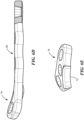
- head portion 74 is also preferably bent upwardly and lies in a different plane than shaft portion 62.
- head portion 74 is bent both upwardly, twisted, and bent to the right or left depending on whether the leg undergoing the TPLO procedure is a right leg or a left leg.
- the upward bend angle may be 24° and the head portion 74
- Fig. 6E bottom surface may be anatomically contoured as shown at 73 to match the contour of a typical rotated cut tibial segment.
- Fig. 6F shows a twist bend (e.g., 27°) of the nose of the head end of the plate.
- Fig. 6G shows the head 74 before the twist bend is made.
- the preferred order of contouring is (1) the bottom surface contour bend, (2) the upward head bend, and (3) the upward head twist.
- the underside contour 73, Fig. 6H bends the entire underside of the plate down at an angle of approximately 45°.
- the proximal contour bends the proximal region of the plate up at angle of approximately 20° as shown in Fig. 6I .
- the bottom surface contour bend may be a bend at a 30 mm radius along the centerline of the plate over a 45° sector.
- the upward bend of the head with respect to the plane of the leg may be 24° and also the head may be bent at an angle with respect to the centerline plane of the plate (e.g., 70.5° with respect to the centerline axis shown in Fig. 6A ).
- the clockwise twist of the head is with respect to the plane of the upward bend of the head.
- the plate may be physically bent or it may be machined to include these preferred bends.
- Fig. 6A also shows how elongated shaft 62 has opposing sides 68a and 68b with spaced curved notches 100 between adjacent screw holes 70a and 70b and then again between screw holes 70b and 70c. These notches reduce the width of the shaft between the screw holes (e.g., by between 25-39% depending on the size of the plate). In this way, the angle ⁇ can be adjusted if needed using a bending tool. These notches also reduce the contact between the shaft bottom surface and the tibia to promote healing.
- Fig. 6B in particular also shows how the bottom of the TPLO plate preferably includes spaced transverse grooves 130 between the screw holes 70a and 70b and between screw holes 70b and 70c machined across the width of the reduced width span between opposing side notches.
- the narrow bone contacting strips or lands 132a, 132b, and 132c are shown in Fig. 6B when there are three screw holes 70a, 70b, and 70c.
- the result is a reduction in contact between the shaft bottom surface and the tibia to promote healing. That is, the bone plate only contacts the bone at strips or lands 132.
- the screw holes in the shaft and head portion may include in a central opening, a plurality of bores spaced around the central opening, and intersection surfaces formed from a common intersection of the central opening and the adjacent bores as shown in the figures. See, U.S. Patent No. 8,506,607 .
- Other types of screw holes may be used including locking, non-locking, combination locking and non-locking, or combinations of the same. See U.S. Patent Nos. 6,623,486 ; 5,709,686 ; and 6,669,70l .
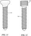
- the locking screw hole includes a countersink 150 above the intersection surfaces 152 for non-locking screw 154, Fig. 11 .
- Locking screw 156, Fig. 12 may also be used with threads 158 on the head thereof configured to engage the intersection surfaces of the locking screw holes configured as set forth in U.S. Patent No. 8,506,607 .
- the bone plates are made of a titanium alloy such as Ti Grade 2, Grade 4, or Ti6Al4V for enhanced biocompatibility.
- Stainless steel 316LVM may also be used.
- a matte/satin finish may be provided to prevent glare of the plate during surgery.
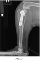
- Fig. 13 shows how a prior TPLO bone plate ( Fig. 4 ) failed to properly fit the anatomy causing the distal part of the plate to kick forward resulting in suboptimal placement of the distal screws (too cranial or too caudal).
- Fig. 14 shows the proper fit provided by the TPLO bone plate of the invention.
- plate 60' has non-locking holes 82a', 82b' and 82c' in head portion 74 and non-locking dynamic compression holes 70a' and 70a' in shaft 62.
- Proximal 200a and distal 200b k-wire holes may be provided for temporary fixation to prevent the plate from shifting during locking screw insertion.
- Leg distal 202a and head proximal 202b beveled ends may be provided to facilitate tunneling of the bone plate under soft tissues in a minimally invasive manner.
- a registration mark such as a laser etched line 206 is preferably provided at the junction between head portion 74 and shaft portion 62 on the top surface of the plate to assist the surgeon in correctly placing the plate. The contour of line 206 matches and is placed over the cut of the upper tibia. See Fig. 14 .
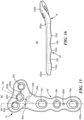
- Figs. 17-18 show snap on drill guide plate 300 here configured to match the contours of a cloverleaf style head bone plate (see Fig. 7 ). Similar snap on drill guide plates will match the size and contours of all the bone plates styles and sizes.
- a given drill guide plate will include a bone plate matching head 304 and leg section 306 each with drill guide ports (e.g., raised cylinders) 302 oriented to overlie the bone plate screw holes.
- Each port will receive a standard drill guide (typically a tube with a pilot hole for the drill bit) in order to ensure a given bone screw does not, for example, proceed into the knee joint.
- the drill guide ports are correctly oriented to optimally insert a given bone screw at the correct angle.
- the leg section 306 includes depending periphery sidewall 310 contoured to fit over the periphery of the bone plate leg section side surfaces.
- Other snap fit means may be used to releasably retain the drill guide plate on the bone plate during drilling operations.
Landscapes
- Health & Medical Sciences (AREA)
- Orthopedic Medicine & Surgery (AREA)
- Surgery (AREA)
- Life Sciences & Earth Sciences (AREA)
- Biomedical Technology (AREA)
- Public Health (AREA)
- Veterinary Medicine (AREA)
- Engineering & Computer Science (AREA)
- Nuclear Medicine, Radiotherapy & Molecular Imaging (AREA)
- Heart & Thoracic Surgery (AREA)
- Medical Informatics (AREA)
- Molecular Biology (AREA)
- Animal Behavior & Ethology (AREA)
- General Health & Medical Sciences (AREA)
- Neurology (AREA)
- Dentistry (AREA)
- Oral & Maxillofacial Surgery (AREA)
- Surgical Instruments (AREA)
Claims (14)
- Knochenplatte (60), die zum Sichern des gedrehten geschnittenen Segments einer oberen Tibia an einem unteren Teil der Tibia als Teil eines Tibiaplateau-Nivellierungsosteotomieeingriffs für ein Tier bemessen ist, wobei die Knochenplatte (60) gekennzeichnet ist durch:einen länglichen Schaft (62) mit einer oberen Fläche (64) und einer unteren Knochenkontaktschaftfläche (66) zwischen entgegengesetzten Seiten (68) des länglichen Schafts (62) der Knochenplatte (60);Schaftschraublöcher (70) in dem länglichen Schaft (62), die sich von der oberen Fläche (64) zu der unteren Knochenkontaktschaftfläche (66) erstrecken, zum Sichern des länglichen Schafts (62) an dem unteren Teil der Tibia;einen Kopfteil (74), der in Bezug auf den länglichen Schaft (62) gebogen ist und mit einer oberen Fläche (76) und einer unteren Knochenkontaktkopfteilfläche (78) zwischen Seitenwänden (80) des Kopfteils (74) der Knochenplatte (60);Kopfteilschraublöcher (82) in dem Kopfteil (74), die sich von der oberen Fläche (76) zu der unteren Knochenkontaktkopfteilfläche (78) davon erstrecken, zum Sichern des Kopfteils (74) an dem gedrehten geschnittenen Segment der oberen Tibia; undeinen Übergang (93) zwischen dem länglichen Schaft (62) und dem Kopfteil (74), beinhaltend entgegengesetzte konkave Seitenwände (95), wobei der längliche Schaft (62) eine Mittellinie (90) aufweist, die sich zentral zwischen den entgegengesetzten Seiten (68) des länglichen Schafts (62) befindet, und der gebogene Kopfteil (74) eine Mittellinie (92) aufweist, die sich zentral zwischen entgegengesetzten Seitenwänden (80) des Kopfteils (74) befindet und in Bezug auf die Mittellinie (90) des länglichen Schafts (62) in einem Winkel von 25°-30° abgewinkelt ist, um den länglichen Schaft (62) kollinear oder ungefähr kollinear in Bezug auf den unteren Teil der Tibia anzuordnen und den Kopfteil (74) an das gedrehte geschnittene Segment der oberen Tibia anzupassen;wobei der Kopfteil (74) zwei äußere Kopfteilschraublöcher (82a, 82c), eine erste äußere Nase (83a) um ein äußeres Kopfteilschraubloch (82a) und eine zweite äußere Nase (83b) um das andere äußere Kopfteilschraubloch (82c), eine Senke (81) zwischen den zwei äußeren Nasen (83a, 83b) an der Mittellinie (92) des Kopfteils (74), so dass der Kopfteil (74) eine Sichelform aufweist, und ein drittes Kopfteilschraubloch (82b) zwischen den zwei äußeren Kopfteilschraublöchern (82a, 82c) beinhaltet;die Mittellinie (90) des länglichen Schafts (62) alle Schaftschraublöcher (70) in zwei Teile teilt unddie Mittellinie (92) des Kopfteils (74) sich mit dem dritten Kopfteilschraubloch (82b) schneidet.
- Knochenplatte (60) nach Anspruch 1, wobei der längliche Schaft (62) in einer ersten Ebene liegt und der Kopfteil (74) nach oben gebogen ist und in einer zweiten Ebene liegt, die in Bezug auf die erste Ebene abgewinkelt ist, und der Kopfteil (74) eine verdrehte Biegung aufweist.
- Knochenplatte (60) nach Anspruch 2, wobei der Kopfteil (74) eine untere Knochenkontaktkopfteilfläche (78) aufweist, die anatomisch konturiert ist, um der Kontur des gedrehten geschnittenen Tibiasegments zu entsprechen.
- Knochenplatte (60) nach Anspruch 1, wobei die entgegengesetzten Seiten (68) des länglichen Schafts (62) beabstandete gewölbte Kerben (100) zum weiteren Biegen des Kopfteils (74) in Bezug auf den länglichen Schaft (62) aufweisen, um den besagten Winkel θ zwischen der Mittellinie (92) des Kopfteils (74) und der Mittellinie (90) des länglichen Schafts (62) während eines TPLO-Eingriffs zu variieren.
- Knochenplatte (60) nach Anspruch 4, wobei die beabstandeten gewölbten Kerben (100) zwischen benachbarten Schraublöchern (70) in dem länglichen Schaft (62) angeordnet sind.
- Knochenplatte (60) nach Anspruch 1, wobei die untere Knochenkontaktschaftfläche (66) des länglichen Schafts beabstandete Quernuten (130) beinhaltet, um einen Kontakt zwischen der unteren Fläche (66) des länglichen Schafts und dem unteren Teil der Tibia zu verringern.
- Knochenplatte (60) nach Anspruch 1, wobei die Schraublöcher (70, 82) in dem länglichen Schaft (62) und/oder dem Kopfteil (74) eine zentrale Öffnung, eine Vielzahl von Bohrungen, die um die besagte zentrale Öffnung beabstandet sind, und Schnittflächen, die von einem gemeinsamen Schnittpunkt der zentralen Öffnung und benachbarten Bohrungen gebildet werden, beinhalten.
- Knochenplatte (60) nach Anspruch 7, wobei ein oder mehrere Schraublöcher (70, 82) weiterhin eine Ansenkung (150) über Schnittflächen (152) für eine konventionelle Schraube (154) beinhalten.
- Knochenplatte (60) nach Anspruch 1, wobei die Knochenplatte (60) aus einer Titanlegierung hergestellt ist.
- Knochenplatte (60) nach Anspruch 1, weiterhin beinhaltend ein oder mehrere K-Drahtlöcher (200).
- Knochenplatte (60) nach Anspruch 1, wobei der Schaft (62) ein angeschrägtes distales Ende (202a) aufweist.
- Knochenplatte (60) nach Anspruch 1, wobei der Kopfteil (74) ein angeschrägtes proximales Ende (202b) aufweist.
- Knochenplatte (60) nach Anspruch 1, weiterhin beinhaltend eine konturierte Registrierungsmarkierung (206) auf der oberen Fläche (76, 64) der Platte (60) nahe des Übergangs (93), um einen Chirurgen beim Platzieren der Knochenplatte (60) auf dem gedrehten geschnittenen Segment der oberen Tibia zu unterstützen.
- Knochenplatte (60) nach Anspruch 1, konfiguriert als eine Bohrerführungsplatte (300) und weiterhin beinhaltend Bohrerführungsbuchsen (302), die sich von der oberen Schaftfläche (64) und der Kopfteilfläche (76) nach oben erstrecken und dazu ausgerichtet sind, die Schraublöcher (70, 82) in einer Knochenplatte (60) zu überlagern.
Applications Claiming Priority (2)
| Application Number | Priority Date | Filing Date | Title |
|---|---|---|---|
| US201562150524P | 2015-04-21 | 2015-04-21 | |
| PCT/US2016/028343 WO2016172142A1 (en) | 2015-04-21 | 2016-04-20 | Tplo bone plate |
Publications (3)
| Publication Number | Publication Date |
|---|---|
| EP3285671A1 EP3285671A1 (de) | 2018-02-28 |
| EP3285671A4 EP3285671A4 (de) | 2018-12-12 |
| EP3285671B1 true EP3285671B1 (de) | 2024-09-18 |
Family
ID=57143393
Family Applications (1)
| Application Number | Title | Priority Date | Filing Date |
|---|---|---|---|
| EP16783714.5A Active EP3285671B1 (de) | 2015-04-21 | 2016-04-20 | Tplo-knochenplatte |
Country Status (4)
| Country | Link |
|---|---|
| US (1) | US10258396B2 (de) |
| EP (1) | EP3285671B1 (de) |
| ES (1) | ES2987374T3 (de) |
| WO (1) | WO2016172142A1 (de) |
Families Citing this family (31)
| Publication number | Priority date | Publication date | Assignee | Title |
|---|---|---|---|---|
| US11259851B2 (en) | 2003-08-26 | 2022-03-01 | DePuy Synthes Products, Inc. | Bone plate |
| US11291484B2 (en) | 2004-01-26 | 2022-04-05 | DePuy Synthes Products, Inc. | Highly-versatile variable-angle bone plate system |
| US9987063B2 (en) * | 2014-04-22 | 2018-06-05 | Stryker European Holdings I, Llc | Plates with countersinks |
| US10226288B2 (en) * | 2014-11-10 | 2019-03-12 | Biomedtrix, Llc | Osteotomy plate for long bones |
| US10905476B2 (en) | 2016-09-08 | 2021-02-02 | DePuy Synthes Products, Inc. | Variable angle bone plate |
| US10820930B2 (en) | 2016-09-08 | 2020-11-03 | DePuy Synthes Products, Inc. | Variable angle bone plate |
| US10624686B2 (en) | 2016-09-08 | 2020-04-21 | DePuy Synthes Products, Inc. | Variable angel bone plate |
| EP4108194B1 (de) | 2018-03-02 | 2025-10-29 | Stryker European Operations Limited | Knochenplatten und zugehörige schrauben |
| US11224468B2 (en) * | 2018-03-02 | 2022-01-18 | Globus Medical, Inc. | Distal tibial plating system |
| US11026727B2 (en) | 2018-03-20 | 2021-06-08 | DePuy Synthes Products, Inc. | Bone plate with form-fitting variable-angle locking hole |
| US10772665B2 (en) * | 2018-03-29 | 2020-09-15 | DePuy Synthes Products, Inc. | Locking structures for affixing bone anchors to a bone plate, and related systems and methods |
| US11013541B2 (en) | 2018-04-30 | 2021-05-25 | DePuy Synthes Products, Inc. | Threaded locking structures for affixing bone anchors to a bone plate, and related systems and methods |
| US10925651B2 (en) | 2018-12-21 | 2021-02-23 | DePuy Synthes Products, Inc. | Implant having locking holes with collection cavity for shavings |
| US10864026B2 (en) * | 2019-02-08 | 2020-12-15 | Steris Instrument Management Services, Inc. | Tibial fixation plate |
| US11571206B2 (en) | 2019-07-23 | 2023-02-07 | Robert Glen Coleman | Tibial plateau leveling osteotomy systems and methods |
| US12295629B2 (en) | 2019-09-20 | 2025-05-13 | Movora, Llc | Tibial plateau leveling osteotomy plate with offset |
| USD945623S1 (en) * | 2019-09-20 | 2022-03-08 | New Generation Devices, Inc. | Tibial plate |
| US12213710B2 (en) | 2019-09-20 | 2025-02-04 | Movora, Llc | Tibial plateau leveling osteotomy plate with offset |
| US11337740B2 (en) | 2020-04-29 | 2022-05-24 | OsteoCertus, LLC | Bone plate and method for use in a tibial plateau leveling osteotomy (TPLO) |
| USD1018854S1 (en) | 2020-09-21 | 2024-03-19 | Movora, Llc | Tibial plate |
| US11963847B2 (en) | 2021-11-03 | 2024-04-23 | DePuy Synthes Products, Inc. | TPLO plate compression system and method |
| WO2023114389A1 (en) | 2021-12-17 | 2023-06-22 | Trilliant Surgical Llc | Orthopedic plate for treatment of bone fractures and related methods |
| USD1017036S1 (en) | 2022-01-27 | 2024-03-05 | Paragon 28, Inc. | Bone plate |
| USD1017037S1 (en) * | 2022-01-27 | 2024-03-05 | Paragon 28, Inc. | Bone plate |
| EP4248890B1 (de) * | 2022-03-23 | 2025-05-21 | Arthrex Inc | Distale humerus-frakturplatten für die veterinärmedizin |
| EP4514250A2 (de) * | 2022-04-28 | 2025-03-05 | Paragon 28, Inc. | Orthopädische implantate, instrumentensysteme und verfahren zur verwendung |
| US12402923B2 (en) | 2022-10-04 | 2025-09-02 | DePuy Synthes Products, Inc. | Offset hole for TPLO compression |
| WO2024074735A1 (es) * | 2022-10-04 | 2024-04-11 | Osteobionix, S.L. | Placa para osteotomía en cuña de cierre, en la parte proximal del cúbito de animales de compañía |
| CN117137606B (zh) * | 2023-09-18 | 2026-01-16 | 合肥伦烁科技有限公司 | 一种tplo动物专用骨板 |
| WO2025155624A1 (en) * | 2024-01-16 | 2025-07-24 | Samuel Patrick Franklin | Device for animal tibial osteotomy stabilization |
| US12502211B1 (en) | 2025-01-17 | 2025-12-23 | Tplo Company Llc | Implant device for a tibial plateau leveling osteotomy |
Family Cites Families (30)
| Publication number | Priority date | Publication date | Assignee | Title |
|---|---|---|---|---|
| US536453A (en) | 1895-03-26 | Gravity-dam | ||
| US5304180A (en) * | 1992-01-17 | 1994-04-19 | Slocum D Barclay | Tibial osteotomy fixation plate |
| KR100329539B1 (ko) | 1995-03-27 | 2002-11-13 | 신테스 아게 츄어 | 뼈고정판 |
| EP0909143A4 (de) * | 1996-06-14 | 2008-11-26 | Depuy Ace Medical Company | Knochenplatte für obere extremitäten |
| ATE257674T1 (de) | 1999-09-13 | 2004-01-15 | Synthes Ag | Knochenplattenvorrichtung |
| BR0017018A (pt) | 2000-01-27 | 2002-11-05 | Synthes Ag | Placa de osso |
| US6767351B2 (en) | 2000-02-01 | 2004-07-27 | Hand Innovations, Inc. | Fixation system with multidirectional stabilization pegs |
| US20020156474A1 (en) | 2001-04-20 | 2002-10-24 | Michael Wack | Polyaxial locking plate |
| US20050240187A1 (en) * | 2004-04-22 | 2005-10-27 | Huebner Randall J | Expanded fixation of bones |
| US8523919B2 (en) | 2010-09-27 | 2013-09-03 | Acumed Llc | Targeting guide with a radiopaque marker to facilitate positioning a bone plate on bone |
| US7722653B2 (en) | 2003-03-26 | 2010-05-25 | Greatbatch Medical S.A. | Locking bone plate |
| USD536453S1 (en) | 2004-03-25 | 2007-02-06 | Precimed S.A. | Bone plate |
| US7137987B2 (en) * | 2004-07-02 | 2006-11-21 | Wright Medical Technology, Inc. | Distal radius bone plating system with locking and non-locking screws |
| US20060173458A1 (en) | 2004-10-07 | 2006-08-03 | Micah Forstein | Bone fracture fixation system |
| US20060149275A1 (en) | 2004-12-14 | 2006-07-06 | Cadmus Calvin M | Apparatus and methods for tibial plateau leveling osteotomy |
| US7771457B2 (en) * | 2005-01-28 | 2010-08-10 | Orthohelix Surgical Designs, Inc. | Orthopedic plate for use in small bone repair |
| US8382807B2 (en) * | 2005-07-25 | 2013-02-26 | Smith & Nephew, Inc. | Systems and methods for using polyaxial plates |
| US8177818B2 (en) | 2005-09-08 | 2012-05-15 | Securos, Inc. | Fixation plate |
| US8523921B2 (en) * | 2006-02-24 | 2013-09-03 | DePuy Synthes Products, LLC | Tibial plateau leveling osteotomy plate |
| US8808334B2 (en) | 2006-03-07 | 2014-08-19 | Orthohelix Surgical Designs, Inc. | Orthopedic plate |
| DE202006019220U1 (de) | 2006-12-19 | 2007-05-24 | Zrinski Ag | Orthopädisches Schraubenverschlusssystem |
| US8262707B2 (en) | 2008-07-31 | 2012-09-11 | Biomet C.V. | Periarticular bone plate with biplanar offset head member |
| US20100057133A1 (en) * | 2008-08-26 | 2010-03-04 | Simon William H | Tibia-talus-calcaneus (T-T-C) locking plate |
| US8936615B2 (en) * | 2010-04-27 | 2015-01-20 | DePuy Synthes Products, LLC | Bone fixation system including K-wire compression |
| EP2405402A1 (de) | 2010-07-06 | 2012-01-11 | EADS Construcciones Aeronauticas, S.A. | Verfahren und System zur Zusammenstellung von Komponenten |
| US10299841B2 (en) * | 2013-11-05 | 2019-05-28 | Arthrex, Inc. | TPLO plate with suture holes for rotational stability |
| US10182855B2 (en) * | 2014-06-30 | 2019-01-22 | DePuy Synthes Products, Inc. | Phalangeal head plate |
| CN203954787U (zh) | 2014-07-25 | 2014-11-26 | 河南众英环保工程有限责任公司 | 一种格栅清污机 |
| CN203953787U (zh) | 2014-07-28 | 2014-11-26 | 苏州市康力骨科器械有限公司 | 一种胫骨平台后柱锁定钢板 |
| US10226288B2 (en) * | 2014-11-10 | 2019-03-12 | Biomedtrix, Llc | Osteotomy plate for long bones |
-
2016
- 2016-04-20 WO PCT/US2016/028343 patent/WO2016172142A1/en not_active Ceased
- 2016-04-20 US US15/133,434 patent/US10258396B2/en active Active
- 2016-04-20 EP EP16783714.5A patent/EP3285671B1/de active Active
- 2016-04-20 ES ES16783714T patent/ES2987374T3/es active Active
Also Published As
| Publication number | Publication date |
|---|---|
| WO2016172142A1 (en) | 2016-10-27 |
| US20160310184A1 (en) | 2016-10-27 |
| EP3285671A4 (de) | 2018-12-12 |
| EP3285671A1 (de) | 2018-02-28 |
| ES2987374T3 (es) | 2024-11-14 |
| US10258396B2 (en) | 2019-04-16 |
Similar Documents
| Publication | Publication Date | Title |
|---|---|---|
| EP3285671B1 (de) | Tplo-knochenplatte | |
| US10993751B1 (en) | Orthopedic implant in the form of a plate to be fixed between two bone parts | |
| US10631902B2 (en) | Bone shortening device and method | |
| CN102724927B (zh) | 颚骨固定板 | |
| EP3318208B1 (de) | Distale radiusfrakturfixierungsplatte mit integriertem und einstellbarem hohlhandseitigem ellenfacetteträger | |
| US8579946B2 (en) | Anatomical distal radius fracture fixation plate | |
| US9370386B2 (en) | Plating concept for distal radial fractures | |
| US20100217327A1 (en) | Plate and system for lateral treatment of a fracture of the calcaneus | |
| CN109310456B (zh) | 接骨板以及接骨板系统 | |
| JP7326381B2 (ja) | 指節骨頭部プレート | |
| JP7589420B2 (ja) | 鎖骨セグメント化プレートシステム | |
| WO2017208318A1 (ja) | 骨プレートおよび骨プレートシステム | |
| CN105395242A (zh) | 一种胫骨近端接骨板系统 | |
| US9763710B2 (en) | Modular proximal femoral osteotomy blade-plate assembly and related fixation method | |
| US20260069331A1 (en) | Lateral proximal tibia plate with extension arm | |
| US11096731B2 (en) | Orthopaedic fracture reduction-fixation tool |
Legal Events
| Date | Code | Title | Description |
|---|---|---|---|
| STAA | Information on the status of an ep patent application or granted ep patent |
Free format text: STATUS: THE INTERNATIONAL PUBLICATION HAS BEEN MADE |
|
| PUAI | Public reference made under article 153(3) epc to a published international application that has entered the european phase |
Free format text: ORIGINAL CODE: 0009012 |
|
| STAA | Information on the status of an ep patent application or granted ep patent |
Free format text: STATUS: REQUEST FOR EXAMINATION WAS MADE |
|
| 17P | Request for examination filed |
Effective date: 20171019 |
|
| AK | Designated contracting states |
Kind code of ref document: A1 Designated state(s): AL AT BE BG CH CY CZ DE DK EE ES FI FR GB GR HR HU IE IS IT LI LT LU LV MC MK MT NL NO PL PT RO RS SE SI SK SM TR |
|
| AX | Request for extension of the european patent |
Extension state: BA ME |
|
| DAV | Request for validation of the european patent (deleted) | ||
| DAX | Request for extension of the european patent (deleted) | ||
| A4 | Supplementary search report drawn up and despatched |
Effective date: 20181114 |
|
| RIC1 | Information provided on ipc code assigned before grant |
Ipc: A61B 17/17 20060101ALI20181108BHEP Ipc: A61B 17/80 20060101AFI20181108BHEP |
|
| 19U | Interruption of proceedings before grant |
Effective date: 20221030 |
|
| 19W | Proceedings resumed before grant after interruption of proceedings |
Effective date: 20230201 |
|
| RAP3 | Party data changed (applicant data changed or rights of an application transferred) |
Owner name: MWI VETERINARY SUPPLY CO. |
|
| RAP3 | Party data changed (applicant data changed or rights of an application transferred) |
Owner name: MWI VETERINARY SUPPLY CO. |
|
| GRAP | Despatch of communication of intention to grant a patent |
Free format text: ORIGINAL CODE: EPIDOSNIGR1 |
|
| STAA | Information on the status of an ep patent application or granted ep patent |
Free format text: STATUS: GRANT OF PATENT IS INTENDED |
|
| INTG | Intention to grant announced |
Effective date: 20240313 |
|
| P01 | Opt-out of the competence of the unified patent court (upc) registered |
Effective date: 20240426 |
|
| GRAJ | Information related to disapproval of communication of intention to grant by the applicant or resumption of examination proceedings by the epo deleted |
Free format text: ORIGINAL CODE: EPIDOSDIGR1 |
|
| STAA | Information on the status of an ep patent application or granted ep patent |
Free format text: STATUS: REQUEST FOR EXAMINATION WAS MADE |
|
| GRAS | Grant fee paid |
Free format text: ORIGINAL CODE: EPIDOSNIGR3 |
|
| STAA | Information on the status of an ep patent application or granted ep patent |
Free format text: STATUS: GRANT OF PATENT IS INTENDED |
|
| GRAP | Despatch of communication of intention to grant a patent |
Free format text: ORIGINAL CODE: EPIDOSNIGR1 |
|
| INTC | Intention to grant announced (deleted) | ||
| INTG | Intention to grant announced |
Effective date: 20240716 |
|
| GRAA | (expected) grant |
Free format text: ORIGINAL CODE: 0009210 |
|
| STAA | Information on the status of an ep patent application or granted ep patent |
Free format text: STATUS: THE PATENT HAS BEEN GRANTED |
|
| AK | Designated contracting states |
Kind code of ref document: B1 Designated state(s): AL AT BE BG CH CY CZ DE DK EE ES FI FR GB GR HR HU IE IS IT LI LT LU LV MC MK MT NL NO PL PT RO RS SE SI SK SM TR |
|
| REG | Reference to a national code |
Ref country code: GB Ref legal event code: FG4D |
|
| REG | Reference to a national code |
Ref country code: CH Ref legal event code: EP |
|
| REG | Reference to a national code |
Ref country code: DE Ref legal event code: R096 Ref document number: 602016089459 Country of ref document: DE |
|
| REG | Reference to a national code |
Ref country code: IE Ref legal event code: FG4D |
|
| REG | Reference to a national code |
Ref country code: ES Ref legal event code: FG2A Ref document number: 2987374 Country of ref document: ES Kind code of ref document: T3 Effective date: 20241114 |
|
| REG | Reference to a national code |
Ref country code: LT Ref legal event code: MG9D |
|
| PG25 | Lapsed in a contracting state [announced via postgrant information from national office to epo] |
Ref country code: NO Free format text: LAPSE BECAUSE OF FAILURE TO SUBMIT A TRANSLATION OF THE DESCRIPTION OR TO PAY THE FEE WITHIN THE PRESCRIBED TIME-LIMIT Effective date: 20241218 |
|
| PG25 | Lapsed in a contracting state [announced via postgrant information from national office to epo] |
Ref country code: GR Free format text: LAPSE BECAUSE OF FAILURE TO SUBMIT A TRANSLATION OF THE DESCRIPTION OR TO PAY THE FEE WITHIN THE PRESCRIBED TIME-LIMIT Effective date: 20241219 Ref country code: FI Free format text: LAPSE BECAUSE OF FAILURE TO SUBMIT A TRANSLATION OF THE DESCRIPTION OR TO PAY THE FEE WITHIN THE PRESCRIBED TIME-LIMIT Effective date: 20240918 |
|
| PG25 | Lapsed in a contracting state [announced via postgrant information from national office to epo] |
Ref country code: BG Free format text: LAPSE BECAUSE OF FAILURE TO SUBMIT A TRANSLATION OF THE DESCRIPTION OR TO PAY THE FEE WITHIN THE PRESCRIBED TIME-LIMIT Effective date: 20240918 |
|
| PG25 | Lapsed in a contracting state [announced via postgrant information from national office to epo] |
Ref country code: LV Free format text: LAPSE BECAUSE OF FAILURE TO SUBMIT A TRANSLATION OF THE DESCRIPTION OR TO PAY THE FEE WITHIN THE PRESCRIBED TIME-LIMIT Effective date: 20240918 |
|
| PG25 | Lapsed in a contracting state [announced via postgrant information from national office to epo] |
Ref country code: HR Free format text: LAPSE BECAUSE OF FAILURE TO SUBMIT A TRANSLATION OF THE DESCRIPTION OR TO PAY THE FEE WITHIN THE PRESCRIBED TIME-LIMIT Effective date: 20240918 |
|
| REG | Reference to a national code |
Ref country code: NL Ref legal event code: MP Effective date: 20240918 |
|
| PG25 | Lapsed in a contracting state [announced via postgrant information from national office to epo] |
Ref country code: RS Free format text: LAPSE BECAUSE OF FAILURE TO SUBMIT A TRANSLATION OF THE DESCRIPTION OR TO PAY THE FEE WITHIN THE PRESCRIBED TIME-LIMIT Effective date: 20241218 |
|
| PG25 | Lapsed in a contracting state [announced via postgrant information from national office to epo] |
Ref country code: RS Free format text: LAPSE BECAUSE OF FAILURE TO SUBMIT A TRANSLATION OF THE DESCRIPTION OR TO PAY THE FEE WITHIN THE PRESCRIBED TIME-LIMIT Effective date: 20241218 Ref country code: NO Free format text: LAPSE BECAUSE OF FAILURE TO SUBMIT A TRANSLATION OF THE DESCRIPTION OR TO PAY THE FEE WITHIN THE PRESCRIBED TIME-LIMIT Effective date: 20241218 Ref country code: LV Free format text: LAPSE BECAUSE OF FAILURE TO SUBMIT A TRANSLATION OF THE DESCRIPTION OR TO PAY THE FEE WITHIN THE PRESCRIBED TIME-LIMIT Effective date: 20240918 Ref country code: HR Free format text: LAPSE BECAUSE OF FAILURE TO SUBMIT A TRANSLATION OF THE DESCRIPTION OR TO PAY THE FEE WITHIN THE PRESCRIBED TIME-LIMIT Effective date: 20240918 Ref country code: GR Free format text: LAPSE BECAUSE OF FAILURE TO SUBMIT A TRANSLATION OF THE DESCRIPTION OR TO PAY THE FEE WITHIN THE PRESCRIBED TIME-LIMIT Effective date: 20241219 Ref country code: FI Free format text: LAPSE BECAUSE OF FAILURE TO SUBMIT A TRANSLATION OF THE DESCRIPTION OR TO PAY THE FEE WITHIN THE PRESCRIBED TIME-LIMIT Effective date: 20240918 Ref country code: BG Free format text: LAPSE BECAUSE OF FAILURE TO SUBMIT A TRANSLATION OF THE DESCRIPTION OR TO PAY THE FEE WITHIN THE PRESCRIBED TIME-LIMIT Effective date: 20240918 |
|
| REG | Reference to a national code |
Ref country code: AT Ref legal event code: MK05 Ref document number: 1724048 Country of ref document: AT Kind code of ref document: T Effective date: 20240918 |
|
| PG25 | Lapsed in a contracting state [announced via postgrant information from national office to epo] |
Ref country code: NL Free format text: LAPSE BECAUSE OF FAILURE TO SUBMIT A TRANSLATION OF THE DESCRIPTION OR TO PAY THE FEE WITHIN THE PRESCRIBED TIME-LIMIT Effective date: 20240918 |
|
| PG25 | Lapsed in a contracting state [announced via postgrant information from national office to epo] |
Ref country code: PT Free format text: LAPSE BECAUSE OF FAILURE TO SUBMIT A TRANSLATION OF THE DESCRIPTION OR TO PAY THE FEE WITHIN THE PRESCRIBED TIME-LIMIT Effective date: 20250120 Ref country code: IS Free format text: LAPSE BECAUSE OF FAILURE TO SUBMIT A TRANSLATION OF THE DESCRIPTION OR TO PAY THE FEE WITHIN THE PRESCRIBED TIME-LIMIT Effective date: 20250118 |
|
| PG25 | Lapsed in a contracting state [announced via postgrant information from national office to epo] |
Ref country code: RO Free format text: LAPSE BECAUSE OF FAILURE TO SUBMIT A TRANSLATION OF THE DESCRIPTION OR TO PAY THE FEE WITHIN THE PRESCRIBED TIME-LIMIT Effective date: 20240918 Ref country code: SM Free format text: LAPSE BECAUSE OF FAILURE TO SUBMIT A TRANSLATION OF THE DESCRIPTION OR TO PAY THE FEE WITHIN THE PRESCRIBED TIME-LIMIT Effective date: 20240918 |
|
| PG25 | Lapsed in a contracting state [announced via postgrant information from national office to epo] |
Ref country code: EE Free format text: LAPSE BECAUSE OF FAILURE TO SUBMIT A TRANSLATION OF THE DESCRIPTION OR TO PAY THE FEE WITHIN THE PRESCRIBED TIME-LIMIT Effective date: 20240918 Ref country code: AT Free format text: LAPSE BECAUSE OF FAILURE TO SUBMIT A TRANSLATION OF THE DESCRIPTION OR TO PAY THE FEE WITHIN THE PRESCRIBED TIME-LIMIT Effective date: 20240918 |
|
| PG25 | Lapsed in a contracting state [announced via postgrant information from national office to epo] |
Ref country code: PL Free format text: LAPSE BECAUSE OF FAILURE TO SUBMIT A TRANSLATION OF THE DESCRIPTION OR TO PAY THE FEE WITHIN THE PRESCRIBED TIME-LIMIT Effective date: 20240918 Ref country code: CZ Free format text: LAPSE BECAUSE OF FAILURE TO SUBMIT A TRANSLATION OF THE DESCRIPTION OR TO PAY THE FEE WITHIN THE PRESCRIBED TIME-LIMIT Effective date: 20240918 |
|
| PG25 | Lapsed in a contracting state [announced via postgrant information from national office to epo] |
Ref country code: SK Free format text: LAPSE BECAUSE OF FAILURE TO SUBMIT A TRANSLATION OF THE DESCRIPTION OR TO PAY THE FEE WITHIN THE PRESCRIBED TIME-LIMIT Effective date: 20240918 |
|
| REG | Reference to a national code |
Ref country code: DE Ref legal event code: R097 Ref document number: 602016089459 Country of ref document: DE |
|
| PGFP | Annual fee paid to national office [announced via postgrant information from national office to epo] |
Ref country code: DE Payment date: 20250416 Year of fee payment: 10 |
|
| PG25 | Lapsed in a contracting state [announced via postgrant information from national office to epo] |
Ref country code: DK Free format text: LAPSE BECAUSE OF FAILURE TO SUBMIT A TRANSLATION OF THE DESCRIPTION OR TO PAY THE FEE WITHIN THE PRESCRIBED TIME-LIMIT Effective date: 20240918 |
|
| PGFP | Annual fee paid to national office [announced via postgrant information from national office to epo] |
Ref country code: ES Payment date: 20250513 Year of fee payment: 10 |
|
| PGFP | Annual fee paid to national office [announced via postgrant information from national office to epo] |
Ref country code: IT Payment date: 20250418 Year of fee payment: 10 |
|
| PLBE | No opposition filed within time limit |
Free format text: ORIGINAL CODE: 0009261 |
|
| STAA | Information on the status of an ep patent application or granted ep patent |
Free format text: STATUS: NO OPPOSITION FILED WITHIN TIME LIMIT |
|
| 26N | No opposition filed |
Effective date: 20250619 |
|
| PG25 | Lapsed in a contracting state [announced via postgrant information from national office to epo] |
Ref country code: SE Free format text: LAPSE BECAUSE OF FAILURE TO SUBMIT A TRANSLATION OF THE DESCRIPTION OR TO PAY THE FEE WITHIN THE PRESCRIBED TIME-LIMIT Effective date: 20240918 |
|
| REG | Reference to a national code |
Ref country code: CH Ref legal event code: H13 Free format text: ST27 STATUS EVENT CODE: U-0-0-H10-H13 (AS PROVIDED BY THE NATIONAL OFFICE) Effective date: 20251125 |
|
| PG25 | Lapsed in a contracting state [announced via postgrant information from national office to epo] |
Ref country code: LU Free format text: LAPSE BECAUSE OF NON-PAYMENT OF DUE FEES Effective date: 20250420 |
|
| PG25 | Lapsed in a contracting state [announced via postgrant information from national office to epo] |
Ref country code: MC Free format text: LAPSE BECAUSE OF FAILURE TO SUBMIT A TRANSLATION OF THE DESCRIPTION OR TO PAY THE FEE WITHIN THE PRESCRIBED TIME-LIMIT Effective date: 20240918 |
|
| REG | Reference to a national code |
Ref country code: BE Ref legal event code: MM Effective date: 20250430 |
|
| PG25 | Lapsed in a contracting state [announced via postgrant information from national office to epo] |
Ref country code: BE Free format text: LAPSE BECAUSE OF NON-PAYMENT OF DUE FEES Effective date: 20250430 |
|
| PG25 | Lapsed in a contracting state [announced via postgrant information from national office to epo] |
Ref country code: CH Free format text: LAPSE BECAUSE OF NON-PAYMENT OF DUE FEES Effective date: 20250430 |
|
| PGFP | Annual fee paid to national office [announced via postgrant information from national office to epo] |
Ref country code: GB Payment date: 20260311 Year of fee payment: 11 |
|
| PG25 | Lapsed in a contracting state [announced via postgrant information from national office to epo] |
Ref country code: IE Free format text: LAPSE BECAUSE OF NON-PAYMENT OF DUE FEES Effective date: 20250420 |
|
| PGFP | Annual fee paid to national office [announced via postgrant information from national office to epo] |
Ref country code: FR Payment date: 20260317 Year of fee payment: 11 |