EP3285702B1 - Vorrichtung zur vertebralen druckentlastung - Google Patents
Vorrichtung zur vertebralen druckentlastung Download PDFInfo
- Publication number
- EP3285702B1 EP3285702B1 EP16733124.8A EP16733124A EP3285702B1 EP 3285702 B1 EP3285702 B1 EP 3285702B1 EP 16733124 A EP16733124 A EP 16733124A EP 3285702 B1 EP3285702 B1 EP 3285702B1
- Authority
- EP
- European Patent Office
- Prior art keywords
- support means
- user
- decompression device
- vertebral
- electronic control
- Prior art date
- Legal status (The legal status is an assumption and is not a legal conclusion. Google has not performed a legal analysis and makes no representation as to the accuracy of the status listed.)
- Active
Links
Images


Classifications
-
- A—HUMAN NECESSITIES
- A61—MEDICAL OR VETERINARY SCIENCE; HYGIENE
- A61H—PHYSICAL THERAPY APPARATUS, e.g. DEVICES FOR LOCATING OR STIMULATING REFLEX POINTS IN THE BODY; ARTIFICIAL RESPIRATION; MASSAGE; BATHING DEVICES FOR SPECIAL THERAPEUTIC OR HYGIENIC PURPOSES OR SPECIFIC PARTS OF THE BODY
- A61H1/00—Apparatus for passive exercising; Vibrating apparatus; Chiropractic devices, e.g. body impacting devices, external devices for briefly extending or aligning unbroken bones
- A61H1/02—Stretching or bending or torsioning apparatus for exercising
- A61H1/0292—Stretching or bending or torsioning apparatus for exercising for the spinal column
-
- A—HUMAN NECESSITIES
- A61—MEDICAL OR VETERINARY SCIENCE; HYGIENE
- A61F—FILTERS IMPLANTABLE INTO BLOOD VESSELS; PROSTHESES; DEVICES PROVIDING PATENCY TO, OR PREVENTING COLLAPSING OF, TUBULAR STRUCTURES OF THE BODY, e.g. STENTS; ORTHOPAEDIC, NURSING OR CONTRACEPTIVE DEVICES; FOMENTATION; TREATMENT OR PROTECTION OF EYES OR EARS; BANDAGES, DRESSINGS OR ABSORBENT PADS; FIRST-AID KITS
- A61F5/00—Orthopaedic methods or devices for non-surgical treatment of bones or joints; Nursing devices ; Anti-rape devices
- A61F5/01—Orthopaedic devices, e.g. long-term immobilising or pressure directing devices for treating broken or deformed bones such as splints, casts or braces
- A61F5/02—Orthopaedic corsets
- A61F5/022—Orthopaedic corsets consisting of one or more shells
-
- A—HUMAN NECESSITIES
- A61—MEDICAL OR VETERINARY SCIENCE; HYGIENE
- A61F—FILTERS IMPLANTABLE INTO BLOOD VESSELS; PROSTHESES; DEVICES PROVIDING PATENCY TO, OR PREVENTING COLLAPSING OF, TUBULAR STRUCTURES OF THE BODY, e.g. STENTS; ORTHOPAEDIC, NURSING OR CONTRACEPTIVE DEVICES; FOMENTATION; TREATMENT OR PROTECTION OF EYES OR EARS; BANDAGES, DRESSINGS OR ABSORBENT PADS; FIRST-AID KITS
- A61F5/00—Orthopaedic methods or devices for non-surgical treatment of bones or joints; Nursing devices ; Anti-rape devices
- A61F5/01—Orthopaedic devices, e.g. long-term immobilising or pressure directing devices for treating broken or deformed bones such as splints, casts or braces
- A61F5/02—Orthopaedic corsets
- A61F5/028—Braces for providing support to the lower back, e.g. lumbo sacral supports
-
- A—HUMAN NECESSITIES
- A61—MEDICAL OR VETERINARY SCIENCE; HYGIENE
- A61F—FILTERS IMPLANTABLE INTO BLOOD VESSELS; PROSTHESES; DEVICES PROVIDING PATENCY TO, OR PREVENTING COLLAPSING OF, TUBULAR STRUCTURES OF THE BODY, e.g. STENTS; ORTHOPAEDIC, NURSING OR CONTRACEPTIVE DEVICES; FOMENTATION; TREATMENT OR PROTECTION OF EYES OR EARS; BANDAGES, DRESSINGS OR ABSORBENT PADS; FIRST-AID KITS
- A61F5/00—Orthopaedic methods or devices for non-surgical treatment of bones or joints; Nursing devices ; Anti-rape devices
- A61F5/01—Orthopaedic devices, e.g. long-term immobilising or pressure directing devices for treating broken or deformed bones such as splints, casts or braces
- A61F5/04—Devices for stretching or reducing fractured limbs; Devices for distractions; Splints
-
- A—HUMAN NECESSITIES
- A61—MEDICAL OR VETERINARY SCIENCE; HYGIENE
- A61H—PHYSICAL THERAPY APPARATUS, e.g. DEVICES FOR LOCATING OR STIMULATING REFLEX POINTS IN THE BODY; ARTIFICIAL RESPIRATION; MASSAGE; BATHING DEVICES FOR SPECIAL THERAPEUTIC OR HYGIENIC PURPOSES OR SPECIFIC PARTS OF THE BODY
- A61H1/00—Apparatus for passive exercising; Vibrating apparatus; Chiropractic devices, e.g. body impacting devices, external devices for briefly extending or aligning unbroken bones
- A61H1/02—Stretching or bending or torsioning apparatus for exercising
- A61H1/0218—Drawing-out devices
-
- A—HUMAN NECESSITIES
- A61—MEDICAL OR VETERINARY SCIENCE; HYGIENE
- A61H—PHYSICAL THERAPY APPARATUS, e.g. DEVICES FOR LOCATING OR STIMULATING REFLEX POINTS IN THE BODY; ARTIFICIAL RESPIRATION; MASSAGE; BATHING DEVICES FOR SPECIAL THERAPEUTIC OR HYGIENIC PURPOSES OR SPECIFIC PARTS OF THE BODY
- A61H2201/00—Characteristics of apparatus not provided for in the preceding codes
- A61H2201/12—Driving means
- A61H2201/1207—Driving means with electric or magnetic drive
- A61H2201/123—Linear drive
-
- A—HUMAN NECESSITIES
- A61—MEDICAL OR VETERINARY SCIENCE; HYGIENE
- A61H—PHYSICAL THERAPY APPARATUS, e.g. DEVICES FOR LOCATING OR STIMULATING REFLEX POINTS IN THE BODY; ARTIFICIAL RESPIRATION; MASSAGE; BATHING DEVICES FOR SPECIAL THERAPEUTIC OR HYGIENIC PURPOSES OR SPECIFIC PARTS OF THE BODY
- A61H2201/00—Characteristics of apparatus not provided for in the preceding codes
- A61H2201/12—Driving means
- A61H2201/1238—Driving means with hydraulic or pneumatic drive
-
- A—HUMAN NECESSITIES
- A61—MEDICAL OR VETERINARY SCIENCE; HYGIENE
- A61H—PHYSICAL THERAPY APPARATUS, e.g. DEVICES FOR LOCATING OR STIMULATING REFLEX POINTS IN THE BODY; ARTIFICIAL RESPIRATION; MASSAGE; BATHING DEVICES FOR SPECIAL THERAPEUTIC OR HYGIENIC PURPOSES OR SPECIFIC PARTS OF THE BODY
- A61H2201/00—Characteristics of apparatus not provided for in the preceding codes
- A61H2201/50—Control means thereof
- A61H2201/5007—Control means thereof computer controlled
-
- A—HUMAN NECESSITIES
- A61—MEDICAL OR VETERINARY SCIENCE; HYGIENE
- A61H—PHYSICAL THERAPY APPARATUS, e.g. DEVICES FOR LOCATING OR STIMULATING REFLEX POINTS IN THE BODY; ARTIFICIAL RESPIRATION; MASSAGE; BATHING DEVICES FOR SPECIAL THERAPEUTIC OR HYGIENIC PURPOSES OR SPECIFIC PARTS OF THE BODY
- A61H2201/00—Characteristics of apparatus not provided for in the preceding codes
- A61H2201/50—Control means thereof
- A61H2201/5058—Sensors or detectors
- A61H2201/5061—Force sensors
-
- A—HUMAN NECESSITIES
- A61—MEDICAL OR VETERINARY SCIENCE; HYGIENE
- A61H—PHYSICAL THERAPY APPARATUS, e.g. DEVICES FOR LOCATING OR STIMULATING REFLEX POINTS IN THE BODY; ARTIFICIAL RESPIRATION; MASSAGE; BATHING DEVICES FOR SPECIAL THERAPEUTIC OR HYGIENIC PURPOSES OR SPECIFIC PARTS OF THE BODY
- A61H2201/00—Characteristics of apparatus not provided for in the preceding codes
- A61H2201/50—Control means thereof
- A61H2201/5058—Sensors or detectors
- A61H2201/5064—Position sensors
-
- A—HUMAN NECESSITIES
- A61—MEDICAL OR VETERINARY SCIENCE; HYGIENE
- A61H—PHYSICAL THERAPY APPARATUS, e.g. DEVICES FOR LOCATING OR STIMULATING REFLEX POINTS IN THE BODY; ARTIFICIAL RESPIRATION; MASSAGE; BATHING DEVICES FOR SPECIAL THERAPEUTIC OR HYGIENIC PURPOSES OR SPECIFIC PARTS OF THE BODY
- A61H2201/00—Characteristics of apparatus not provided for in the preceding codes
- A61H2201/50—Control means thereof
- A61H2201/5097—Control means thereof wireless
Definitions
- the present invention relates to a spinal decompression device. It finds in particular an application for relieving people suffering from back pain, caused for example by a herniated disc. Such pain occurs, among other things, because the vertebrae excessively compress the intervertebral discs separating them from each other.
- Relief can be obtained by exerting a distraction force on the spine, so as to decoapt the vertebrae.
- decoaptation is meant the increase of the interarticular space between two surfaces that are too close to each other.
- Such a device is for example proposed by the document EP 0 319 224 , which describes a spinal decompression device configured to surround a portion of a user's trunk, comprising an upper support, a lower support, and two telescoping bars mounted on the lower and upper supports so as to exert a spreading force on the lower and upper supports.
- US 5,462,518 A describes a spinal decompression device comprising actuators arranged in a V shape.
- the telescopic bars include an actuation lever by which a third party, such as a healthcare professional, can, when the device is worn by the user, move the lower and upper supports away from each other, to exert a distraction force on the user's spine.
- a third party such as a healthcare professional
- such a device is particularly bulky, and in particular cannot be worn under clothing. Furthermore, it significantly reduces the user's mobility, so that it cannot be worn for more than a few minutes. Furthermore, it must be installed and operated with the help of a third party. It also does not allow the spreading force exerted by the telescopic bars to be adapted, for example according to the movements made by the user, so that, for example when the user moves, the distraction effort varies, which tends to limit the relief provided by the device.
- the present invention aims to resolve, among others, the above-described shortcomings of the spinal decompression devices known from the prior art, by proposing a spinal decompression device with which the user can equip himself and which he can wear throughout the day, discreetly and effectively, the intensity of the distraction force applied to the spinal column being constant, independently of the position or movement of the user.
- the invention relates to a spinal decompression device configured to surround the trunk of a user, comprising upper support means configured to surround a first part of the trunk, lower support means configured to surround a second part of the trunk and elongation means mounted on the upper support means and on the lower support means and configured to exert a separation force on the lower and upper support means tending to move the lower support means away from the upper support means; furthermore, the device comprises an electronic control system for controlling the elongation means so as to maintain a determined distraction force on the user's spine.
- the second part of the trunk is arranged under the first part of the trunk.
- the user can operate the device alone.
- the effectiveness of the device is improved, the relief enjoyed by the user not varying, in particular, depending on his movements and/or his position.
- the elongation means comprise a power source, such as a battery, by which they can be operated without external assistance.
- a power source such as a battery
- the electronic control system includes adjustment means for varying the intensity of the distraction effort.
- the device and more particularly the intensity of the distraction effort on the user's spine, are adapted to relieve users with, for example, different morphologies or suffering from pain of different intensities.
- the presence of the adjustment means makes it possible to adapt the device to changes in the user's condition.
- the spinal decompression device further comprises measuring means configured to measure at least one characteristic relating to the movements of the user.
- the electronic control system is configured to modify the spreading force exerted by the elongation means as a function of the measurements made by the measuring means.
- the value and/or direction of the spreading force can also be modified depending on the characteristics of the user measured by the measuring means, so that the intensity of the distraction effort is constant, independently, for example, of the movements of the user.
- the electronic control system is configured to modify the intensity of the distraction effort based on the measurements made by the measuring means.
- the adjustment means is configured to modify the intensity of the distraction effort according to the mobility of the user, or their position.
- the spinal decompression device further comprises means for recording the measurements taken by the measuring means.
- the recording means thus make it possible to memorize all or part of the user's movements and positions during the period in which he is equipped with the device, so as, for example, to identify behaviors which may be the cause of or contribute to his back pain.
- the elongation means comprise at least one linear actuator.
- said at least one linear actuator is mounted articulated relative to the upper support means and/or to the lower support means.
- the electronic control system is configured to limit the relative movements of said at least one linear actuator relative to the upper support means and/or the lower support means.
- the elongation means comprise at least a first and a second linear actuator configured to extend on each side of the trunk, when the device is worn by the user.
- the elongation means comprise two pairs of linear actuators configured to extend on each side of the trunk, when the device is worn by the user.
- the spreading force exerted by the elongation means is even better distributed over the user's trunk; furthermore, it allows better mobility of the user equipped with the device according to the present invention, and even greater efficiency of the device.
- the linear actuators of a pair are inclined relative to each other, so as to further increase the freedom of movement of the user when wearing the spinal decompression device according to the present invention, while making it possible, through the presence of the electronic control system, to prevent the user from performing certain movements which could be painful for him.
- the linear actuators of the same pair are arranged in a V shape.
- the tip of the V formed by the linear actuators of the same pair is directed downwards.
- the linear actuators extend in a direction inclined relative to the axis of the spine.
- the linear actuators of the elongation means are configured to exert separation forces of different value and direction.
- This arrangement makes it possible to better distribute the distraction force on the spinal column, so as to increase the effectiveness of the device according to the present invention.
- the upper and lower support means are configured to be fitted around the trunk portion they surround.
- the upper and lower support means comprise an adjustable belt, configured to adapt the device to different user morphologies.
- the upper and lower support means have a substantially conical shape, so as to increase the stability of the attachment of the device to the user's trunk, and, consequently, the precision of the location and intensity of the distraction force that it applies to the user's spine.
- the present invention also relates to a spinal decompression system comprising a spinal decompression device according to the present invention, and a data processing system, the electronic control system of the spinal decompression device further comprising wireless transmission means configured to transmit the measurements made by the measurement means to the processing system.
- the system is configured to allow an exchange of data between the user and a third party, such as a healthcare professional, so as to adjust the prescription relating to the conditions of use of the device, such as the intensity of the distraction effort.
- a third party such as a healthcare professional
- the wireless transmission means are configured to transmit to the processing system data relating to the elongation means, such as variations in the value and/or direction of the spreading force.
- the wireless transmission means are configured to transmit to the processing system the data recorded by the recording means.
- the processing system can process data relating to a significant period of use of the device according to the present invention.
- the processing system comprises a storage device configured to record the data transmitted by the wireless transmission means of the electronic control system.
- the third party can compare, during successive exchanges with the device, the data received, so as, for example, to evaluate the effectiveness of the parameter changes applied.
- the spinal decompression device 10 comprises upper support means 12, lower support means 14 and elongation means 16 which, as will be detailed in the remainder of the description, are mounted both on the upper support means 12 and on the lower support means 14, the elongation means 16 being configured to exert a separation force on the lower and upper support means 14, 12, tending to move the lower support means 14 away from the lower support means 12.
- the spinal decompression device 10 further comprises an electronic control system 18 fixed, for example and in a non-limiting manner, to the upper support means 12.
- the device 10 also comprises measuring means 20 and recording means 22 which will be described in more detail below.
- the upper support means 12 and the lower support means 14 comprise different portions of textile 24, 26, 28, 30, connected, for example, and in a non-limiting manner, by elastic bands 32, 34, configured to adapt the upper and lower support means 12, 14 to the morphology of the user.
- the upper and lower support means have closing means 36, 38, in this case a clip-on strap, making it easier to equip the user.
- THE figures 1 And 2 represent in particular the device 10 worn by a user, whose silhouette is symbolized by mixed lines.
- the upper support means 12 thus have the shape of a belt, configured to surround a first part of a user's torso; for example and in a non-limiting manner, the upper support means 12 are configured to surround the middle part of the user's torso.
- the lower support means 14 have the shape of a belt, configured to surround a second part of a user's trunk, for example and in a non-limiting manner, a part of the user's abdominal strap.
- the upper 12 and lower 14 support means are configured so as to surround a portion of the user's spine, for example and in a non-limiting manner, the lumbar segment of the spine.
- the lower and upper support means 14, 12 comprise a material having non-allergenic properties; they can further be coated, for example, with a thermoformable foam, so as to even better adapt the spinal decompression device 10 to the morphology of the user and to improve the cooperation between the support means 12, 14 and the user's trunk.
- the upper 12 and lower 14 support means have a conical shape configured to further improve the cooperation of the lower and upper support means 14, 12 with the user's trunk.
- the elongation means 16 comprise a first 40 and a second 42 pairs of linear actuators, the first and second pairs 40, 42 being configured to extend on each side of the trunk, when the device 10 is worn by the user.
- each of the pairs 40, 42 comprises a first and a second linear actuator 44, 44', 46, 46'.
- the different linear actuators 44, 44', 46, 46' are electric cylinders; it would of course be possible to design, without departing from the scope of the present invention, any other type of linear actuator, such as for example a hydraulic cylinder.
- Each of the actuators has a longitudinal direction and first and second ends opposite each other; as shown in particular in the figures 1 And 2 , one end of the linear actuators is mounted on the upper support means 12, the other end being mounted on the lower support means 14.
- the linear actuators 44, 44', 46, 46' comprise ball joints mounted on each of their ends, and configured so that the different linear actuators are articulated relative to the upper support means 12 and to the lower support means 14.
- the linear actuators are mounted by pockets formed on the upper and lower support means 12, 14, and more particularly on their textile portions 24, 26, 28, 30, the ends of the various linear actuators being housed in said pockets; it would of course be possible to design, without departing from the scope of the present invention, any other means of mounting the linear actuators on the support means 12, 14.
- the elongation means 16 further comprise batteries 50 mounted, for example and in a non-limiting manner, on the rear portion of the upper and lower support means 12, 14.
- rear portion is meant the portion of the spinal decompression device 10 configured to cover a portion of the user's back, when the device 10 is worn.
- the batteries 50 are configured to operate the linear actuators; one could conceive, without departing from the scope of the present invention, any other power source allowing the linear actuators to be operated without external assistance.
- the linear actuators are configured to exert a separation force on the upper 12 and lower 14 support means, the exertion of such a separation force making it possible, thanks to the adhesion of the upper and lower support means 12, 14 on the parts of the user's trunk, by moving the lower support means 14 away from the upper support means 12, to apply a distraction force on the user's spine.
- the electronic control system 18 of the device 10 is configured to control the elongation means 16 so as to maintain a determined distraction force on the user's spine.
- the electronic control system 18 comprises an electronic plate making it possible to control the value and/or direction of the spreading force exerted by the linear actuators 44, 44', 46, 46'.
- the electronic control system 18 of the device 10 is configured to control the elongation means 16 so as to regulate the spreading force that the linear actuators 44, 44', 46, 46' exert on the lower and upper support means 14, 12 ; by regulation is meant a variation in the value of the spreading force and/or a variation in the direction of application of said spreading force.
- the measuring means 20 are configured to measure at least one characteristic relating to the movements of the user, such as his position, his movement or the relative movements of different parts of his body; for example and in a non-limiting manner, the measuring means 20 comprise an accelerometer, a gyrometer, or any other sensor making it possible to determine the relative position of the different parts of the user.
- the electronic control system 18 is further configured to modify the value and/or the direction of the separation force exerted by the linear actuators of the elongation means 16 as a function of the measurements carried out by the measuring means 20.
- the electronic control system 18 thus makes it possible to adjust the value and/or the direction of the separation force exerted by the different linear actuators 44, 44', 46, 46', to take into account the variation in the intensity of the distraction force.
- the recording means 22 are configured to record the measurements made by the measuring means 20. Such recording of the measurements is particularly useful for enabling, for example, a health professional to adapt the intensity of the distraction effort to be applied to the user's spine, to adapt the prescription relating to wearing the device or even to provide the user with advice relating to movements and/or positions which could increase the pain felt and/or delay healing.
- first and second pairs 40, 42 of the linear actuators each have a V shape, the longitudinal direction of each of the linear actuators being inclined relative to the axis of the spinal column.
- This arrangement allows, among other things, to better distribute the force exerted by the linear actuators, without hindering the freedom of movement of the user equipped with the device 10.
- the spinal decompression device 10 makes it possible to maintain a determined distraction effort on the user's spine, without compromising the user's mobility.
- the spinal decompression device 10 according to the present invention constitutes an exoskeleton making it possible to support part of the user's back.
- the electronic control system 18 of the device 10 is further configured to limit the relative movements of the linear actuators 44, 44', 46, 46' relative to the upper and lower support means 12, 14, so that the user cannot perform movements which could injure him or increase his pain.
- the device 10 according to the present invention has a reduced bulk, such that it can be worn discreetly, under the user's usual clothing.
- elongation means 16 comprising semi-active actuators, such as linear actuators cooperating with springs, such semi-active actuators making it possible to store all or part of the energy released by certain movements of the user and to reuse this stored energy during other movements carried out by the user.
- the electronic control system 18 also includes adjustment means 60 making it possible to modify the intensity of the distraction force applied to the user's spine using the separation force of the elongation means 16.
- the adjustment means 60 is thus configured to allow a healthcare professional to adjust the setting of the device 10 to the morphology and the pain felt by the user.
- the electronic control system 18 comprises wireless transmission means 62 allowing, among other things, the transmission of the measurements carried out by the measuring means 20.
- wireless transmission means 62 which are configured to transmit the variations in values of the separation force exerted by the elongation means 16 during use of the device 10.
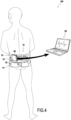
- the invention also relates to a spinal decompression system 100 comprising a spinal decompression device 10 according to the present invention and a data processing system 80, for example installed in a computing device such as a computer or a smartphone, the data processing system 80 being configured to receive the data transmitted by the wireless transmission means 62 of the electronic control system 18.
- a spinal decompression system 100 comprising a spinal decompression device 10 according to the present invention and a data processing system 80, for example installed in a computing device such as a computer or a smartphone, the data processing system 80 being configured to receive the data transmitted by the wireless transmission means 62 of the electronic control system 18.
- the spinal decompression system thus allows a third party, such as a healthcare professional, to access the user's data without the user necessarily having to remove the device 10 or even be in proximity to the third party.
- the wireless transmission means 62 are configured to transmit to the data processing system 80 the data relating to the elongation means 16, such as the variations in the value and/or the direction of the separation force.
- the wireless transmission means 62 are also configured to transmit to the data processing system 80 the data recorded by the recording means 22; it is also possible to conceive of the presence of a storage device in the data processing system 80 configured to record the data transmitted by the wireless transmission means 62 of the electronic control system 18 of the spinal decompression device 10.
- the invention although particularly suitable for lower back pain, can also be adapted to relieve any other type of back pain, such as cervical or thoracic pain.
Landscapes
- Health & Medical Sciences (AREA)
- Life Sciences & Earth Sciences (AREA)
- Veterinary Medicine (AREA)
- Public Health (AREA)
- General Health & Medical Sciences (AREA)
- Animal Behavior & Ethology (AREA)
- Biomedical Technology (AREA)
- Engineering & Computer Science (AREA)
- Orthopedic Medicine & Surgery (AREA)
- Vascular Medicine (AREA)
- Heart & Thoracic Surgery (AREA)
- Nursing (AREA)
- Epidemiology (AREA)
- Pain & Pain Management (AREA)
- Physical Education & Sports Medicine (AREA)
- Rehabilitation Therapy (AREA)
- Neurology (AREA)
- Prostheses (AREA)
- Orthopedics, Nursing, And Contraception (AREA)
Claims (10)
- Wirbelsäulendekompressionsvorrichtung (10), die dazu ausgestaltet ist, den Rumpf eines Benutzers zu umgeben, umfassend:- obere Stützmittel (12), die dazu ausgestaltet sind, einen ersten Teil des Rumpfes zu umgeben;- untere Stützmittel (14), die dazu ausgestaltet sind, einen zweiten Teil des Rumpfes zu umgeben;- Verlängerungsmittel (16), die an den oberen Stützmitteln (12) und an den unteren Stützmitteln (14) montiert und dazu ausgestaltet sind, eine Abstandskraft auf die unteren und oberen Stützmittel auszuüben, die dazu dient, die unteren Stützmittel und die oberen Stützmittel fernzuhalten;wobei die Vorrichtung ferner ein elektronisches Steuersystem (18) zum Steuern der Verlängerungsmittel (16) beinhaltet, um eine bestimmte Ablenkungsanstrengung auf die Wirbelsäule des Benutzers aufrechtzuerhalten,wobei die Verlängerungsmittel zwei Paare an Stellgliedern beinhalten, die dazu ausgestaltet sind, sich von jeder Seite des Rumpfes zu erstrecken, wenn die Vorrichtung durch den Benutzer getragen wird,wobei die Stellglieder eines gleichen Paares in Bezug zueinander geneigt und als V angeordnet sind,wobei die Vorrichtung dadurch gekennzeichnet ist, dass die Spitze des V nach unten gerichtet ist.
- Wirbelsäulendekompressionsvorrichtung (10) nach Anspruch 1, dadurch gekennzeichnet, dass das elektronische Steuersystem (18) ein Einstellmittel (60) beinhaltet, um die Intensität der Ablenkungsanstrengung zu modifizieren.
- Wirbelsäulendekompressionsvorrichtung (10) nach Anspruch 1 oder 2, dadurch gekennzeichnet, dass sie ferner Messmittel (20) beinhaltet, die dazu ausgestaltet sind, zumindest eine Charakteristik relativ zu den Bewegungen des Benutzers zu messen.
- Wirbelsäulendekompressionsvorrichtung (10) nach Anspruch 3, dadurch gekennzeichnet, dass das elektronische Steuersystem (18) dazu ausgestaltet ist, die Abstandskraft, die durch die Verlängerungsmittel (16) ausgeübt wird, in Abhängigkeit von den Messungen, die durch die Messmittel (20) umgesetzt werden, zu modifizieren.
- Wirbelsäulendekompressionsvorrichtung (10) nach Anspruch 3 oder 4, dadurch gekennzeichnet, dass sie ferner Aufzeichnungsmittel (22) für die Messungen, die durch die Messmittel (20) umgesetzt werden, beinhaltet.
- Wirbelsäulendekompressionsvorrichtung (10) nach einem der Ansprüche 1 bis 5, dadurch gekennzeichnet, dass die Stellglieder der Verlängerungsmittel (16) lineare Stellglieder (44, 44', 46, 46') sind.
- Wirbelsäulendekompressionsvorrichtung (10) nach Anspruch 6, dadurch gekennzeichnet, dass die linearen Stellglieder (44, 44`, 46, 46') gelenkig in Bezug auf die oberen Stützmittel (12) und/oder auf die unteren Stützmittel (14) montiert sind.
- Wirbelsäulendekompressionsvorrichtung (10) nach Anspruch 7, dadurch gekennzeichnet, dass das elektronische Steuersystem (18) dazu ausgestaltet ist, die Relativbewegungen der linearen Stellglieder (44, 44', 46, 46') in Bezug auf die oberen Stützmittel und/oder auf die unteren Stützmittel zu begrenzen.
- Wirbelsäulendekompressionsvorrichtung (10) nach einem der Ansprüche 1 bis 8, dadurch gekennzeichnet, dass sich jedes Stellglied in einer Richtung erstreckt, die in Bezug auf die Achse der Wirbelsäule geneigt ist.
- Wirbelsäulendekompressionssystem, das eine Wirbelsäulendekompressionsvorrichtung (10) nach einem der Ansprüche 1 bis 9 und nach Anspruch 3 und ein Datenverarbeitungssystem beinhaltet, wobei das elektronische Steuersystem (18) ferner Drahtlosübertragungsmittel (62) beinhaltet, die dazu ausgestaltet sind, die Messungen, die durch die Messmittel (20) umgesetzt werden, an das Verarbeitungssystem zu übertragen.
Applications Claiming Priority (2)
| Application Number | Priority Date | Filing Date | Title |
|---|---|---|---|
| FR1553515A FR3034981B1 (fr) | 2015-04-20 | 2015-04-20 | Dispositif de decompression vertebrale |
| PCT/FR2016/050810 WO2016170244A1 (fr) | 2015-04-20 | 2016-04-08 | Dispositif de décompression vertébrale |
Publications (3)
| Publication Number | Publication Date |
|---|---|
| EP3285702A1 EP3285702A1 (de) | 2018-02-28 |
| EP3285702C0 EP3285702C0 (de) | 2025-01-08 |
| EP3285702B1 true EP3285702B1 (de) | 2025-01-08 |
Family
ID=53674108
Family Applications (1)
| Application Number | Title | Priority Date | Filing Date |
|---|---|---|---|
| EP16733124.8A Active EP3285702B1 (de) | 2015-04-20 | 2016-04-08 | Vorrichtung zur vertebralen druckentlastung |
Country Status (9)
| Country | Link |
|---|---|
| US (1) | US10932981B2 (de) |
| EP (1) | EP3285702B1 (de) |
| JP (1) | JP6923448B2 (de) |
| KR (1) | KR102550450B1 (de) |
| AU (1) | AU2016252083A1 (de) |
| CA (1) | CA2983043C (de) |
| ES (1) | ES3008100T3 (de) |
| FR (1) | FR3034981B1 (de) |
| WO (1) | WO2016170244A1 (de) |
Families Citing this family (3)
| Publication number | Priority date | Publication date | Assignee | Title |
|---|---|---|---|---|
| CH711550A2 (de) * | 2015-09-18 | 2017-03-31 | Ortho-Team AG | Orthese zur Beckenstabilisation. |
| CN107361895A (zh) * | 2017-08-10 | 2017-11-21 | 深圳市中医院 | 腰部牵引装置 |
| IL280928B2 (en) * | 2021-02-16 | 2023-05-01 | Eyal Ami | A wearable device for active balance of the pelvis and lower back vertebrae |
Citations (2)
| Publication number | Priority date | Publication date | Assignee | Title |
|---|---|---|---|---|
| US20040077982A1 (en) * | 2002-10-17 | 2004-04-22 | Amei Technologies Inc. | Ambulatory cyclic traction device |
| US20090036888A1 (en) * | 2004-12-30 | 2009-02-05 | Dunfee & Dunfee, Llc | Ambulatory spinal unloading method and apparatus |
Family Cites Families (15)
| Publication number | Priority date | Publication date | Assignee | Title |
|---|---|---|---|---|
| US1589670A (en) * | 1924-11-15 | 1926-06-22 | Alf C Kremer | Pneumatic stretcher |
| US2886031A (en) * | 1956-01-10 | 1959-05-12 | Azor D Robbins | Body supports |
| NZ214557A (en) * | 1984-12-18 | 1989-07-27 | Yulorwoh Pty Ltd | Traction device: biasing means includes slide members and springs |
| US4715362A (en) * | 1986-02-27 | 1987-12-29 | Henry Scott | Ambulatory lumbo-sacral traction systems and methods |
| IL84695A0 (en) | 1987-12-02 | 1988-06-30 | Ludwig Shtabholz | Lumbar traction apparatus |
| US5462518A (en) * | 1994-03-07 | 1995-10-31 | Hatley; Charles A. | Therapeutic spinal traction apparatus and multipurpose exercise systems and methods |
| NO180514C (no) * | 1995-01-18 | 1997-05-07 | Svein Ousdal | Anordning ved strekkorsett og nakkestrekker |
| US5651764A (en) * | 1996-03-05 | 1997-07-29 | Chiu; Shui-Shang | Portable apparatus for reforming spine |
| EP1648357A2 (de) | 2003-07-18 | 2006-04-26 | Pneu Medex Inc. | Fluidbetriebene stellglieder und pneumatische, entlastende orthesen |
| FR2896149B1 (fr) * | 2006-01-19 | 2008-12-12 | Gibaud Soc Par Actions Simplif | Ceinture de soutien lombaire |
| US9839553B2 (en) * | 2012-06-20 | 2017-12-12 | Bio Cybernetics International, Inc. | Automated orthotic device with treatment regimen and method for using the same |
| US8845566B2 (en) * | 2012-08-02 | 2014-09-30 | The Regents Of The University Of Michigan | Active exoskeletal spinal orthosis and method of orthotic treatment |
| US20140364784A1 (en) * | 2013-06-05 | 2014-12-11 | Elwha Llc | Time-based control of active toso support |
| US9480593B2 (en) * | 2013-03-15 | 2016-11-01 | University Of Tennessee Research Foundation | Distraction and mobility back support |
| US9987159B2 (en) * | 2014-08-26 | 2018-06-05 | Daniel Charles Williams | Back supporter |
-
2015
- 2015-04-20 FR FR1553515A patent/FR3034981B1/fr active Active
-
2016
- 2016-04-08 AU AU2016252083A patent/AU2016252083A1/en not_active Abandoned
- 2016-04-08 WO PCT/FR2016/050810 patent/WO2016170244A1/fr not_active Ceased
- 2016-04-08 ES ES16733124T patent/ES3008100T3/es active Active
- 2016-04-08 US US15/567,651 patent/US10932981B2/en active Active
- 2016-04-08 EP EP16733124.8A patent/EP3285702B1/de active Active
- 2016-04-08 CA CA2983043A patent/CA2983043C/fr active Active
- 2016-04-08 KR KR1020177033510A patent/KR102550450B1/ko active Active
- 2016-04-08 JP JP2017555690A patent/JP6923448B2/ja active Active
Patent Citations (2)
| Publication number | Priority date | Publication date | Assignee | Title |
|---|---|---|---|---|
| US20040077982A1 (en) * | 2002-10-17 | 2004-04-22 | Amei Technologies Inc. | Ambulatory cyclic traction device |
| US20090036888A1 (en) * | 2004-12-30 | 2009-02-05 | Dunfee & Dunfee, Llc | Ambulatory spinal unloading method and apparatus |
Also Published As
| Publication number | Publication date |
|---|---|
| EP3285702C0 (de) | 2025-01-08 |
| FR3034981B1 (fr) | 2017-05-05 |
| WO2016170244A1 (fr) | 2016-10-27 |
| FR3034981A1 (fr) | 2016-10-21 |
| KR20170139603A (ko) | 2017-12-19 |
| US20180085279A1 (en) | 2018-03-29 |
| AU2016252083A1 (en) | 2017-11-09 |
| KR102550450B1 (ko) | 2023-07-03 |
| US10932981B2 (en) | 2021-03-02 |
| CA2983043C (fr) | 2021-10-26 |
| JP6923448B2 (ja) | 2021-08-18 |
| CA2983043A1 (fr) | 2016-10-27 |
| JP2018516640A (ja) | 2018-06-28 |
| EP3285702A1 (de) | 2018-02-28 |
| ES3008100T3 (en) | 2025-03-21 |
Similar Documents
| Publication | Publication Date | Title |
|---|---|---|
| EP3393731B1 (de) | Hinterer teil für eine exoskelettstruktur | |
| CA3079977C (fr) | Structure d'exosquelette adapte a l'epaule | |
| CA3009897C (fr) | Structure modulaire d'exosquelette pour l'assistance a l'effort d'un utilisateur | |
| EP3393729B1 (de) | Exoskelettstruktur zur bereitstellung von kraftunterstützung für einen benutzer | |
| CA3009549C (fr) | Module de pied pour une structure d'exosquelette | |
| FR3057508B1 (fr) | Dispositif appui-tete | |
| EP3285702A1 (de) | Wirbeldekompressionsvorrichtung | |
| WO2017109190A1 (fr) | Structure modulaire d'exosquelette avec module de support de sac a dos | |
| EP3562627B1 (de) | Verbindungsvorrichtung für eine exoskelettstruktur zur erleichterung des tragens von lasten beim gehen oder laufen | |
| FR3023160A1 (fr) | Fauteuil articule comprenant un mecanisme de verticalisation pour un vehicule roulant. | |
| CH648478A5 (fr) | Dispositif permettant le controle de la flexion d'un membre deficient d'une personne handicapee, membre auquel est associe un appareil orthopedique. | |
| EP1687123A2 (de) | Exoskelettsystem für ein biologisches segment mit proportionaler bewegung und exoskelettanordnung der systeme | |
| CA3088545C (fr) | Porte-sac et equipement comprenant un tel porte-sac | |
| CA3167536C (fr) | Exosquelette autorisant une grande liberte de mouvement de l'epaule | |
| EP2839775A1 (de) | Verrichtung zur relativen Positionsbestimmung eines Femurs im Verhältnis zu einem Schienbein | |
| FR3060144A1 (fr) | Dispositif de lunettes pouvant etre transforme reversiblement en bracelet | |
| WO2018150123A1 (fr) | Système mains libres destine a un utilisateur | |
| EP3200674A1 (de) | Tragbare vorrichtung zur messung physikalischer parameter im zusammenhang mit dem sprunggelenkes einer person und rahmen solch einer vorrichtung | |
| US918940A (en) | Shoulder-brace. | |
| CA3013669C (fr) | Dispositif de mesure d'une force | |
| FR3160606A1 (fr) | Exosquelette d’assistance des mouvements du tronc. | |
| WO2020002513A1 (fr) | Table pour decompresser les vertebres d'un patient | |
| Guillemette | Customer-Centric Design in Wearable Products for Ergonomic Support | |
| EP2022545A1 (de) | Perfektionierung für Befestigungsvorrichtung eines Schuhs auf einem Ski | |
| FR2769511A1 (fr) | Compensateur cervical |
Legal Events
| Date | Code | Title | Description |
|---|---|---|---|
| STAA | Information on the status of an ep patent application or granted ep patent |
Free format text: STATUS: THE INTERNATIONAL PUBLICATION HAS BEEN MADE |
|
| PUAI | Public reference made under article 153(3) epc to a published international application that has entered the european phase |
Free format text: ORIGINAL CODE: 0009012 |
|
| STAA | Information on the status of an ep patent application or granted ep patent |
Free format text: STATUS: REQUEST FOR EXAMINATION WAS MADE |
|
| 17P | Request for examination filed |
Effective date: 20171004 |
|
| AK | Designated contracting states |
Kind code of ref document: A1 Designated state(s): AL AT BE BG CH CY CZ DE DK EE ES FI FR GB GR HR HU IE IS IT LI LT LU LV MC MK MT NL NO PL PT RO RS SE SI SK SM TR |
|
| AX | Request for extension of the european patent |
Extension state: BA ME |
|
| DAV | Request for validation of the european patent (deleted) | ||
| DAX | Request for extension of the european patent (deleted) | ||
| STAA | Information on the status of an ep patent application or granted ep patent |
Free format text: STATUS: EXAMINATION IS IN PROGRESS |
|
| 17Q | First examination report despatched |
Effective date: 20200803 |
|
| GRAP | Despatch of communication of intention to grant a patent |
Free format text: ORIGINAL CODE: EPIDOSNIGR1 |
|
| STAA | Information on the status of an ep patent application or granted ep patent |
Free format text: STATUS: GRANT OF PATENT IS INTENDED |
|
| INTG | Intention to grant announced |
Effective date: 20241018 |
|
| GRAS | Grant fee paid |
Free format text: ORIGINAL CODE: EPIDOSNIGR3 |
|
| GRAA | (expected) grant |
Free format text: ORIGINAL CODE: 0009210 |
|
| STAA | Information on the status of an ep patent application or granted ep patent |
Free format text: STATUS: THE PATENT HAS BEEN GRANTED |
|
| RAP3 | Party data changed (applicant data changed or rights of an application transferred) |
Owner name: JAPET MEDICAL DEVICES |
|
| AK | Designated contracting states |
Kind code of ref document: B1 Designated state(s): AL AT BE BG CH CY CZ DE DK EE ES FI FR GB GR HR HU IE IS IT LI LT LU LV MC MK MT NL NO PL PT RO RS SE SI SK SM TR |
|
| REG | Reference to a national code |
Ref country code: GB Ref legal event code: FG4D Free format text: NOT ENGLISH |
|
| REG | Reference to a national code |
Ref country code: CH Ref legal event code: EP |
|
| REG | Reference to a national code |
Ref country code: DE Ref legal event code: R096 Ref document number: 602016090891 Country of ref document: DE |
|
| REG | Reference to a national code |
Ref country code: IE Ref legal event code: FG4D Free format text: LANGUAGE OF EP DOCUMENT: FRENCH |
|
| U01 | Request for unitary effect filed |
Effective date: 20250115 |
|
| U07 | Unitary effect registered |
Designated state(s): AT BE BG DE DK EE FI FR IT LT LU LV MT NL PT RO SE SI Effective date: 20250121 |
|
| REG | Reference to a national code |
Ref country code: ES Ref legal event code: FG2A Ref document number: 3008100 Country of ref document: ES Kind code of ref document: T3 Effective date: 20250321 |
|
| U20 | Renewal fee for the european patent with unitary effect paid |
Year of fee payment: 10 Effective date: 20250221 |
|
| PG25 | Lapsed in a contracting state [announced via postgrant information from national office to epo] |
Ref country code: RS Free format text: LAPSE BECAUSE OF FAILURE TO SUBMIT A TRANSLATION OF THE DESCRIPTION OR TO PAY THE FEE WITHIN THE PRESCRIBED TIME-LIMIT Effective date: 20250408 |
|
| PG25 | Lapsed in a contracting state [announced via postgrant information from national office to epo] |
Ref country code: PL Free format text: LAPSE BECAUSE OF FAILURE TO SUBMIT A TRANSLATION OF THE DESCRIPTION OR TO PAY THE FEE WITHIN THE PRESCRIBED TIME-LIMIT Effective date: 20250108 |
|
| PGFP | Annual fee paid to national office [announced via postgrant information from national office to epo] |
Ref country code: GB Payment date: 20250417 Year of fee payment: 10 Ref country code: ES Payment date: 20250512 Year of fee payment: 10 |
|
| PG25 | Lapsed in a contracting state [announced via postgrant information from national office to epo] |
Ref country code: NO Free format text: LAPSE BECAUSE OF FAILURE TO SUBMIT A TRANSLATION OF THE DESCRIPTION OR TO PAY THE FEE WITHIN THE PRESCRIBED TIME-LIMIT Effective date: 20250408 Ref country code: IS Free format text: LAPSE BECAUSE OF FAILURE TO SUBMIT A TRANSLATION OF THE DESCRIPTION OR TO PAY THE FEE WITHIN THE PRESCRIBED TIME-LIMIT Effective date: 20250508 |
|
| PG25 | Lapsed in a contracting state [announced via postgrant information from national office to epo] |
Ref country code: HR Free format text: LAPSE BECAUSE OF FAILURE TO SUBMIT A TRANSLATION OF THE DESCRIPTION OR TO PAY THE FEE WITHIN THE PRESCRIBED TIME-LIMIT Effective date: 20250108 |
|
| PG25 | Lapsed in a contracting state [announced via postgrant information from national office to epo] |
Ref country code: GR Free format text: LAPSE BECAUSE OF FAILURE TO SUBMIT A TRANSLATION OF THE DESCRIPTION OR TO PAY THE FEE WITHIN THE PRESCRIBED TIME-LIMIT Effective date: 20250409 |
|
| PGFP | Annual fee paid to national office [announced via postgrant information from national office to epo] |
Ref country code: CH Payment date: 20250501 Year of fee payment: 10 |
|
| PG25 | Lapsed in a contracting state [announced via postgrant information from national office to epo] |
Ref country code: SM Free format text: LAPSE BECAUSE OF FAILURE TO SUBMIT A TRANSLATION OF THE DESCRIPTION OR TO PAY THE FEE WITHIN THE PRESCRIBED TIME-LIMIT Effective date: 20250108 |
|
| PG25 | Lapsed in a contracting state [announced via postgrant information from national office to epo] |
Ref country code: CZ Free format text: LAPSE BECAUSE OF FAILURE TO SUBMIT A TRANSLATION OF THE DESCRIPTION OR TO PAY THE FEE WITHIN THE PRESCRIBED TIME-LIMIT Effective date: 20250108 |
|
| PG25 | Lapsed in a contracting state [announced via postgrant information from national office to epo] |
Ref country code: SK Free format text: LAPSE BECAUSE OF FAILURE TO SUBMIT A TRANSLATION OF THE DESCRIPTION OR TO PAY THE FEE WITHIN THE PRESCRIBED TIME-LIMIT Effective date: 20250108 |
|
| PLBE | No opposition filed within time limit |
Free format text: ORIGINAL CODE: 0009261 |
|
| STAA | Information on the status of an ep patent application or granted ep patent |
Free format text: STATUS: NO OPPOSITION FILED WITHIN TIME LIMIT |
|
| REG | Reference to a national code |
Ref country code: CH Ref legal event code: L10 Free format text: ST27 STATUS EVENT CODE: U-0-0-L10-L00 (AS PROVIDED BY THE NATIONAL OFFICE) Effective date: 20251119 |
|
| 26N | No opposition filed |
Effective date: 20251009 |
|
| PG25 | Lapsed in a contracting state [announced via postgrant information from national office to epo] |
Ref country code: MC Free format text: LAPSE BECAUSE OF FAILURE TO SUBMIT A TRANSLATION OF THE DESCRIPTION OR TO PAY THE FEE WITHIN THE PRESCRIBED TIME-LIMIT Effective date: 20250108 |
|
| U20 | Renewal fee for the european patent with unitary effect paid |
Year of fee payment: 11 Effective date: 20260224 |
|
| PG25 | Lapsed in a contracting state [announced via postgrant information from national office to epo] |
Ref country code: IE Free format text: LAPSE BECAUSE OF NON-PAYMENT OF DUE FEES Effective date: 20250408 |
|
| REG | Reference to a national code |
Ref country code: CH Ref legal event code: U11 Free format text: ST27 STATUS EVENT CODE: U-0-0-U10-U11 (AS PROVIDED BY THE NATIONAL OFFICE) Effective date: 20260504 |