EP3285963B1 - Procédé pour l'usinage complet par meulage de pièces ondulées présentant des parties cylindriques et profilées - Google Patents
Procédé pour l'usinage complet par meulage de pièces ondulées présentant des parties cylindriques et profilées Download PDFInfo
- Publication number
- EP3285963B1 EP3285963B1 EP17708519.8A EP17708519A EP3285963B1 EP 3285963 B1 EP3285963 B1 EP 3285963B1 EP 17708519 A EP17708519 A EP 17708519A EP 3285963 B1 EP3285963 B1 EP 3285963B1
- Authority
- EP
- European Patent Office
- Prior art keywords
- grinding
- workpiece
- clamping
- ground
- tailstock
- Prior art date
- Legal status (The legal status is an assumption and is not a legal conclusion. Google has not performed a legal analysis and makes no representation as to the accuracy of the status listed.)
- Active
Links
Images


Classifications
-
- B—PERFORMING OPERATIONS; TRANSPORTING
- B24—GRINDING; POLISHING
- B24B—MACHINES, DEVICES, OR PROCESSES FOR GRINDING OR POLISHING; DRESSING OR CONDITIONING OF ABRADING SURFACES; FEEDING OF GRINDING, POLISHING, OR LAPPING AGENTS
- B24B27/00—Other grinding machines or devices
- B24B27/0076—Other grinding machines or devices grinding machines comprising two or more grinding tools
-
- B—PERFORMING OPERATIONS; TRANSPORTING
- B24—GRINDING; POLISHING
- B24B—MACHINES, DEVICES, OR PROCESSES FOR GRINDING OR POLISHING; DRESSING OR CONDITIONING OF ABRADING SURFACES; FEEDING OF GRINDING, POLISHING, OR LAPPING AGENTS
- B24B19/00—Single-purpose machines or devices for particular grinding operations not covered by any other main group
- B24B19/009—Single-purpose machines or devices for particular grinding operations not covered by any other main group for grinding profiled workpieces using a profiled grinding tool
-
- B—PERFORMING OPERATIONS; TRANSPORTING
- B23—MACHINE TOOLS; METAL-WORKING NOT OTHERWISE PROVIDED FOR
- B23F—MAKING GEARS OR TOOTHED RACKS
- B23F1/00—Making gear teeth by tools of which the profile matches the profile of the required surface
- B23F1/02—Making gear teeth by tools of which the profile matches the profile of the required surface by grinding
-
- B—PERFORMING OPERATIONS; TRANSPORTING
- B23—MACHINE TOOLS; METAL-WORKING NOT OTHERWISE PROVIDED FOR
- B23Q—DETAILS, COMPONENTS, OR ACCESSORIES FOR MACHINE TOOLS, e.g. ARRANGEMENTS FOR COPYING OR CONTROLLING; MACHINE TOOLS IN GENERAL CHARACTERISED BY THE CONSTRUCTION OF PARTICULAR DETAILS OR COMPONENTS; COMBINATIONS OR ASSOCIATIONS OF METAL-WORKING MACHINES, NOT DIRECTED TO A PARTICULAR RESULT
- B23Q3/00—Devices holding, supporting, or positioning work or tools, of a kind normally removable from the machine
- B23Q3/155—Arrangements for automatic insertion or removal of tools, e.g. combined with manual handling
-
- B—PERFORMING OPERATIONS; TRANSPORTING
- B24—GRINDING; POLISHING
- B24B—MACHINES, DEVICES, OR PROCESSES FOR GRINDING OR POLISHING; DRESSING OR CONDITIONING OF ABRADING SURFACES; FEEDING OF GRINDING, POLISHING, OR LAPPING AGENTS
- B24B19/00—Single-purpose machines or devices for particular grinding operations not covered by any other main group
- B24B19/02—Single-purpose machines or devices for particular grinding operations not covered by any other main group for grinding grooves, e.g. on shafts, in casings, in tubes, homokinetic joint elements
- B24B19/022—Single-purpose machines or devices for particular grinding operations not covered by any other main group for grinding grooves, e.g. on shafts, in casings, in tubes, homokinetic joint elements for helicoidal grooves
-
- B—PERFORMING OPERATIONS; TRANSPORTING
- B24—GRINDING; POLISHING
- B24B—MACHINES, DEVICES, OR PROCESSES FOR GRINDING OR POLISHING; DRESSING OR CONDITIONING OF ABRADING SURFACES; FEEDING OF GRINDING, POLISHING, OR LAPPING AGENTS
- B24B41/00—Component parts such as frames, beds, carriages, headstocks
- B24B41/06—Work supports, e.g. adjustable steadies
- B24B41/061—Work supports, e.g. adjustable steadies axially supporting turning workpieces, e.g. magnetically, pneumatically
- B24B41/062—Work supports, e.g. adjustable steadies axially supporting turning workpieces, e.g. magnetically, pneumatically between centres; Dogs
-
- B—PERFORMING OPERATIONS; TRANSPORTING
- B24—GRINDING; POLISHING
- B24B—MACHINES, DEVICES, OR PROCESSES FOR GRINDING OR POLISHING; DRESSING OR CONDITIONING OF ABRADING SURFACES; FEEDING OF GRINDING, POLISHING, OR LAPPING AGENTS
- B24B41/00—Component parts such as frames, beds, carriages, headstocks
- B24B41/06—Work supports, e.g. adjustable steadies
- B24B41/065—Steady rests
-
- B—PERFORMING OPERATIONS; TRANSPORTING
- B24—GRINDING; POLISHING
- B24B—MACHINES, DEVICES, OR PROCESSES FOR GRINDING OR POLISHING; DRESSING OR CONDITIONING OF ABRADING SURFACES; FEEDING OF GRINDING, POLISHING, OR LAPPING AGENTS
- B24B5/00—Machines or devices designed for grinding surfaces of revolution on work, including those which also grind adjacent plane surfaces; Accessories therefor
- B24B5/02—Machines or devices designed for grinding surfaces of revolution on work, including those which also grind adjacent plane surfaces; Accessories therefor involving centres or chucks for holding work
- B24B5/04—Machines or devices designed for grinding surfaces of revolution on work, including those which also grind adjacent plane surfaces; Accessories therefor involving centres or chucks for holding work for grinding cylindrical surfaces externally
-
- B—PERFORMING OPERATIONS; TRANSPORTING
- B24—GRINDING; POLISHING
- B24B—MACHINES, DEVICES, OR PROCESSES FOR GRINDING OR POLISHING; DRESSING OR CONDITIONING OF ABRADING SURFACES; FEEDING OF GRINDING, POLISHING, OR LAPPING AGENTS
- B24B53/00—Devices or means for dressing or conditioning abrasive surfaces
- B24B53/04—Devices or means for dressing or conditioning abrasive surfaces of cylindrical or conical surfaces on abrasive tools or wheels
- B24B53/053—Devices or means for dressing or conditioning abrasive surfaces of cylindrical or conical surfaces on abrasive tools or wheels using a rotary dressing tool
-
- F—MECHANICAL ENGINEERING; LIGHTING; HEATING; WEAPONS; BLASTING
- F04—POSITIVE - DISPLACEMENT MACHINES FOR LIQUIDS; PUMPS FOR LIQUIDS OR ELASTIC FLUIDS
- F04C—ROTARY-PISTON, OR OSCILLATING-PISTON, POSITIVE-DISPLACEMENT MACHINES FOR LIQUIDS; ROTARY-PISTON, OR OSCILLATING-PISTON, POSITIVE-DISPLACEMENT PUMPS
- F04C2230/00—Manufacture
- F04C2230/10—Manufacture by removing material
-
- F—MECHANICAL ENGINEERING; LIGHTING; HEATING; WEAPONS; BLASTING
- F04—POSITIVE - DISPLACEMENT MACHINES FOR LIQUIDS; PUMPS FOR LIQUIDS OR ELASTIC FLUIDS
- F04C—ROTARY-PISTON, OR OSCILLATING-PISTON, POSITIVE-DISPLACEMENT MACHINES FOR LIQUIDS; ROTARY-PISTON, OR OSCILLATING-PISTON, POSITIVE-DISPLACEMENT PUMPS
- F04C2240/00—Components
- F04C2240/20—Rotors
Definitions
- the invention relates to a method for grinding wavy workpieces having at least one respective cylindrical and profiled section on one and the same grinding machine as complete machining.
- wave-shaped workpieces are understood to mean, for example, gear shafts, rotors for hydraulic pumps or flow meters, rotors for vane pumps and rotors for, for example, compressors for compressors, blowers, vacuum pumps or similar applications.
- the invention described below is also to be used in the sense of a broad interpretation of the term wavy workpieces on other shaft parts such as camshafts, crankshafts, etc. application.
- the required recesses, face sides and diameters are generally ground in separate work sequences and often also in a machine.
- profile sections or toothings likewise to be ground on the wave-shaped workpieces are ground on separate machines.
- the grinding of the cylindrical sections also includes the grinding of flat shoulder surfaces, which are present, for example, between adjacent cylindrical outer surfaces of different diameters.
- DE 199 21 785 B4 is a method for grinding convex treads and outer diameters on shafts having at least one disk-shaped shaft portion and a corresponding grinding machine for carrying out the method.
- the shaft part to be ground is to be ground in terms of a complete machining both with respect to the cylindrical portion or the cylindrical portions and the profile sections.
- the profile sections are described in these methods according to the embodiment described there as a disc-shaped shaft portion with a convex curved surface. Such convexly curved surfaces constitute profile sections.
- the known method is now directed to all grinding operations, ie, a grinding operation for grinding the convex end faces on the disc-shaped shaft portion and a second grinding operation for grinding the respective desired outer diameter or cylindrical portions of the shaft part in FIG be ground to a clamping.
- a grinding operation for grinding the convex end faces on the disc-shaped shaft portion
- a second grinding operation for grinding the respective desired outer diameter or cylindrical portions of the shaft part in FIG be ground to a clamping.
- Out DE 10 2010 005 630 A1 is the basic technical structure of a machine described with which a machining of wavy workpieces according to the previously acknowledged WO 2012/100307 A8 can be done.
- this known grinding center is indeed described above all, that in addition a storage magazine to be arranged for the respective grinding wheels required cooling nozzles or cooling nozzle sets can, in the executed by means of this known grinding center grinding complete machining the workpiece remains fully clamped.
- the object of the invention is to increase the manufacturing accuracy of such complex components as the wavy wavy workpieces with cylindrical and profiled sections to be ground here.
- the workpiece is ground in the grinding machine in a first clamping operation in a first grinding operation and then ground in a second grinding operation, after the first clamping has been released and then a second clamping of the workpiece has been generated.
- Another reason for residual stresses in the workpiece may result from, for example, scrap material also being used in the production of the raw material or the green workpiece, which is still within the allowable technical tolerances for the green workpiece or blank, but for subsequent processing steps can cause additional stresses and related deformations of the workpiece.
- the blanks or green workpieces can be designed in such a way that the grooves or teeth of the profile sections are already pre-machined by milling or other machining processes.
- the improved manufacturing quality results from the fact that by the interim release of the clamping, which otherwise takes place so that the positioning of the workpiece is maintained in the grinding machine, the warping of the workpiece due to the above reasons in the processing by the grinding so to speak "yielded " becomes. This means that the workpiece can relax in the meantime when releasing the tension, so that during subsequent grinding operations it can be sanded again on a relaxed and firmly clamped workpiece.
- the distortion of the workpiece results from the stress released during the machining of the workpieces in the structure of the material. Above all, this relates in particular to the stresses on the surface of the workpiece at the points where grinding is performed. By loosening the clamping of the workpiece, a workpiece that is at least largely stress-free can then be machined more precisely during subsequent renewed clamping and grinding.
- the workpieces are first clamped in the machine, the workpieces being clamped firmly in place between the tips in the machine, as is conventionally known in the art.
- the workpiece In order to be able to grind the profiled areas of the grooves or toothings, the workpiece also has to be clamped radially free of play.
- This is preferably realized by a so-called compensating chuck.
- the workpiece is centered by the point in the chuck, and the jaws bear balancing on the workpiece at its diameter in the clamped between the tips of Werk Swissspindel- and tailstock state, the clamping force is applied by this voltage, the Workpiece compensating and radially stiff, d. H. play-free, tense.
- the chuck In order to be able to drive the workpiece in a program-controlled, targeted manner during machining, the chuck is permanently mounted on a workpiece spindle, whereby the rotation drive takes place about the so-called C-axis.
- this or the clamping jaws can be withdrawn in the open state.
- the workpiece at the shaft end is free, so that the clamping diameter can also be ground.
- the workpiece is clamped only between the centering. The friction between the driven Centering tip and the center in the workpiece transmits the torque required for grinding to the rotation of the workpiece.
- the workpiece to be ground is clamped during the grinding process in such a way that it is clamped between the tips and for the radial entrainment by the chuck is still stretched tightly compensating. Since the shaft parts generally have such a diameter-length ratio that they must be supported during machining, it is preferable to first sand a steady rest seat on the workpiece. However, this is only necessary if the diameter-length ratio requires additional support.
- the grinding of the diameters and the faces is preferably carried out with a grinding wheel, which is designed for peeling grinding.
- the cylindrical section on the workpiece is preferably made with a first, not cylindrical grinding wheel by a longitudinal peel grinding.
- the profiled section is made by profile grinding with a second, profiled grinding wheel.
- the grinding wheel is preferably dressed so that the so-called gate of the grinding wheel is dressed at an angle.
- the main cutting during peeling grinding takes place in the short, conically dressed area of the grinding wheel.
- the outer diameter of the grinding wheel cuts relatively small, d. H. its surface is only used for smoothing the surface. With such a grinding wheel can also be ground flat.
- the first grinding wheel is disposed on a first wheelhead
- the second wheel is further preferably disposed on a second wheelhead.
- the advantage of having separate grinding headstocks for the first grinding wheel and for the second grinding wheel is that there is more flexibility in grinding.
- parallel machining of corresponding areas on the workpiece and arrangement of the grinding headstocks on both sides of the workpiece it can also be achieved that the grinding forces imposed on the workpiece during grinding by the one grinding wheel are at least to a considerable extent compensated by the other grinding wheel.
- the workpiece is clamped between points, which are introduced in the end sides of the workpiece and define its longitudinal axis.
- One of the tips is located on the tailstock and the other tip is located on the workpiece headstock.
- the tip on the tailstock exerts a corresponding clamping pressure by means of an axially directed pressure load which is sufficiently high at least for the grinding of the cylindrical sections and / or the plan sides.
- the tail located on the tailstock can be converted from a state in which the axially directed pressure load is exerted on the workpiece to release the clamping in a pressureless state.
- the tip on the tailstock still engages the centering bore on the workpiece on the side of the workpiece facing the tailstock, thus ensuring the alignment of the workpiece on the longitudinal axis of the workpiece defined by the centering bores.
- the non-pressurized state of the tip on the tailstock gives the workpiece the opportunity to compensate for certain internal stresses released during grinding, so that the workpiece can be ground largely free of internal stress for the next grinding operation when re-clamping between the tips.
- an additional clamping device is provided on the workpiece headstock, which additionally biases the workpiece on the outer circumference of a cylindrical portion.
- the additional clamping device biases the workpiece with its engaging on the circumference of the workpiece clamping jaws.
- the clamping device is also for the purpose of completely relaxing the workpiece, ie for compensating its internal stresses released during grinding to be released when the tip on the tailstock is depressurized.
- At least one steady rest seat is ground in the first grinding operation, and thereafter the profiled section is pre-ground in the second grinding operation.
- the cylindrical portion and the plane surfaces present on the workpiece are then ground, followed by the finish grinding of the profiled portion in a fourth grinding operation.
- the clamping is released in each case between all successive grinding operations and then the workpiece is tensioned again before the respective subsequent grinding operation begins.
- a bezel for supporting the workpiece is preferably employed at this Lünettensitz after it has been ground.
- the support by means of a steady rest is above all advantageous when grinding operations are carried out with longer workpieces, in which only one grinding wheel is engaged with the workpiece.
- the grinding of the steady seat represents the first processing step during which the workpiece is clamped firmly in the machine, i. H. is in the first setup. After grinding the Lünettensitzes then further diameter be pre-ground with any plan surfaces therebetween or even finish ground. Depending on the workpiece geometry, the grinding of the diameters also includes the grinding of plane surfaces connecting the individual diameter ranges of different diameters.
- the present invention is based on the idea that by releasing the clamping between successive grinding operations while ensuring the retention of the workpiece to be ground on the existing through the tips of the workpiece headstock and the tailstock and in the end faces of the workpiece centering defined longitudinal axis internal stresses are reduced, which longitudinal axis represents the referenced reference axis for grinding.
- longitudinal axis represents the referenced reference axis for grinding.
- subsequent grinding operations on the workpiece can then be ground free of such internal stresses or at least significantly reduced internal stresses.
- the subsequent subsequent loosening of the clamping further loops in the presence of a substantially internal tension inside the workpiece in any case leads to improved grinding results, and contrary to the prevailing opinion, according to which the workpiece as far as possible during the entire grinding operations and without intermediate release of the clamping should be kept in this setup.
- the release of the tail stick side can also be done in such a way that the tip is withdrawn by a certain amount, d. H. no longer in the center.
- the workpiece will then rest in this state on so-called Vorablageprismen and then clamped again.
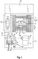
- FIG. 1 is a plan view of a grinding machine for performing the method according to the invention shown in which a workpiece is clamped so that it allows the implementation of the inventive method for grinding complete machining of wavy workpieces or shaft parts 10.
- the grinding machine shown in plan view has as a grinding center a machine stand 1, a arranged on the machine frame 1 workpiece headstock 2 with CNC-controlled C-axis and a tailstock 3. Between the workpiece headstock 2 and the tailstock 3, the workpiece, not shown, is clamped so that its geometric longitudinal axis coincides with the clamping and rotation axis 4.
- a cross slide is parallel, which is indicated by the double arrow marked as Z-axis, and at right angles, which is indicated by the designated as X-axis further double arrow, to the axis of rotation 4 of the workpiece CNC-controlled movable.
- the cross slide carries over vertical guideways 19, CNC-controlled movable, which is represented by the also indicated as a double arrow Y-axis, a first wheelhead 5, to which a grinding spindle 9 is fixed with a grinding wheel 11.
- Another CNC-controlled adjustment consists of a horizontal, perpendicular to the axis of rotation 4 of the workpiece arranged CNC-controlled pivot axis 12, which is marked and shown as A-axis.
- a pivot axis is preferably provided above the carriage for the Z-axis, which has a vertically arranged pivot axis 13 and in FIG. 2 is called B-axis.
- this pivot axis is not shown, since they only for grinding with inclined grinding wheel 11 is required for peel grinding or bevel grinding. This means that it can be ground in the Schräginstechschleif compiler, or it can also cones are ground by pivoting the B-axis. If this B-axis, ie the pivot axis 13, is not present, it is also possible to provide this machining from above onto the shaft diameter.
- a dressing spindle 8 which carries a diamond wheel and is used to dress the grinding wheel 11. Furthermore, a device 14 for changing the grinding wheel 11 is shown.
- the grinding wheels are received in a holder in the manner of a magazine and are fed by means of the Suppliesroboters 15 from the magazine of the respective grinding spindle.
- the conversion robot 15 has a gripper unit 16, by means of which it removes the desired grinding wheel from the supply magazine as required and optionally a specific cooling nozzle set 17 belonging to the grinding wheel and feeds both into the region of the operative position of the grinding wheel on the workpiece. It is also possible that the cooling nozzle set 17 is gripped independently of the grinding wheel with the Arthurroboter and is guided to the loop engagement point, which can be done during grinding.
- a control cabinet 18 which includes the CNC control of the grinding machine with which the grinding machine is controlled.
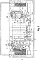
- FIG. 2 is a plan view of a grinding machine for carrying out the method according to the invention shown, which has a first wheelhead 5 and a second wheelhead 20. Only the basic structure of the grinding machine is shown in plan view.
- a workpiece headstock 2 and a tailstock 3 are arranged on a machine stand 1. Between the workpiece headstock 2 and the tailstock 3, the clamping and rotation axis 4 is formed for the workpiece 10, which coincides with the longitudinal axis of the workpiece.
- a chuck 6 mounteded on a workpiece spindle 2a of the workpiece spindle stock 2 (C-axis) is a chuck 6 which receives a centric circumferential tip, not shown, and additionally has compensating jaws 6a (also not shown).
- the first cross slide carries a first wheelhead 5, to which a first grinding spindle 9 is attached with a first grinding wheel 11.
- a dressing spindle 8 is arranged, which serves with its diamond wheel to dress the first grinding wheel 11 of the first grinding headstock 5.
- the device for changing the grinding wheel 11 is in FIG. 2 not shown separately.
- the grinding wheels 11 of the first grinding headstock 5 serve to grind the shank parts or the cylindrical sections on the shaft part, ie all outer diameters for the cylindrical sections, conical sections and similar contours are ground with these grinding wheels.
- FIG. 2 is on the right side a second cross slide parallel, which is marked as a Z2 axis with a double arrow, and at right angles, which is in FIG. 2 as X2-axis is also shown with double arrow, to the rotation axis 4 of the workpiece 10 CNC-controlled movable.
- This second cross slide carries a vertically CNC-controlled movable (Y2 axis) second wheelhead 20, to which a grinding spindle 22 is attached with a second grinding wheel 21.
- Another CNC-controlled adjustment consists of a horizontal, to the rotation axis 4 of the workpiece 10 arranged CNC-controlled pivot axis, which in FIG. 2 represented as A2 axis.
- a grinding spindle is mounted, which serves for receiving the grinding wheel 21.
- this grinding spindle 22 (see FIG. 4B ) can be changed fully automatically programmatically by a likewise not shown grinding wheel changing device these grinding wheels.
- To the second grinding wheel 21 is then - if it is necessary - mitausge (2004) in a known manner, the appropriate coolant lubricant nozzle or the appropriate coolant nozzle set, which is also not shown separately.
- a second dressing device 23 for dressing the grinding wheel 21 for the in FIG. 2 Located on the right grinding wheel head 20 is provided in the front grinder on the right side of the machine.
- FIG. 2 In the rear area of the grinder is the in FIG. 2 not shown switching cabinet, which receives the complete electrical control of the machine.
- the respective workpieces 10 of the grinding machine are supplied in a manner known per se, for example via an internal loading portal or by means of a loading portal arranged above the grinding machine in the sense of loading or unloading or taken out of the machine.
- FIGS. 1 and 2 illustrated basic structure of a grinding machine is used to carry out the method according to the invention, because with this basic structure of the grinding machine, the complete machining of the cylindrical sections, plan sides and profile sections having workpiece is such that released by the processing or during processing in the workpiece internal stresses between grinding operations can be degraded or compensated, so that subsequent grinding operations can always be performed on a workpiece at least largely exempt from internal stresses.
- the course of the method according to the invention will now be explained in detail with reference to the following figures.
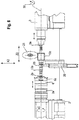
- FIG. 3 is a partial top view of a portion of the method according to the invention realizing grinding machine shown, in which the workpiece is clamped between peaks before the grinding of a steady seat is performed.
- this complete machining of a workpiece 10 in the form of a shaft part is shown in principle.
- This shaft part is received between a workpiece headstock 2 with CNC-controlled C-axis and a tailstock 3 in a clamping between tips 2b, 3a.
- the clamping jaws 6a are released from the workpiece 10 and the chuck is withdrawn with its clamping jaws 6a.
- the workpiece remains firmly clamped between the tips 2b, 3a.
- the entrainment of the workpiece 10 takes place to its rotation by the friction between the centering 2b on the chuck and the present in the workpiece 10 center, in which engages this centering 2b.
- a tailstock 3 is provided, which engages by preferably hydraulic actuation in the center of the centering tip 3a of the tailstock 3 side facing center.
- the tailstock tip 3a is movable in the axial direction of the workpiece, so that with appropriate formation of an axial pressure, the workpiece is held in a centered manner between the two centering 2b and 3a so that a rotational entrainment is ensured by the workpiece headstock 2.
- FIG. 4A is a partial top view according to FIG. 3 shown during roughing of the profile section in the form of a toothing or grooves with staffed / supporting bezel.
- the pre-grinding of the profile section 10c by means of a galvanic grinding wheel 21 This is done in a conventional manner by interpolating method on the CNC-controlled axis or by means of the CNC-controlled axes.
- the electroplated grinding wheels 21 are well suited for pre-grinding, above all because they can realize a very high machining volume per unit of time.
- the clamping of the workpiece to compensate for the internal stresses possibly present in the workpiece by grinding in such a way that the jaws 6a of the chuck 6 solved and the tailstock 3a only depressurized in the center of the shaft part 10 remains.
- the workpiece is no longer firmly clamped, but retains its defined position, which is important in terms of accuracy for subsequent grinding operations.
- the relaxation of the workpiece is preferably useful both after roughing and after the finish grinding of individual sections, at least as long as the complete machining on the workpiece has not been completed.
- FIG. 4a is now shown between the tips 2b and 3a with simultaneously applied chuck 6 with the clamping jaws 6a clamped workpiece 10.
- the workpiece has a shank-side shaft end 10a, cylindrical portions 10b delimited by plan sides, and profile portions 10c.
- a bezel 26 is employed for supporting the relatively long wave-shaped workpiece.
- the chuck 6 with the inner centering 2b is mounted on the workpiece spindle 2a of the workpiece spindle stock 2. If - as in FIG. 4A shown - the profile section 10c is ground by means of the grinding wheel 21, the clamping device 6 remains clamped with their jaws 6a on the shaft side shaft end 10a.
- the grinding wheel 21 can be delivered via its not shown grinding headstock and the grinding spindle 21 carrying the grinding wheel on the two axes X2 and Z2 corresponding to the geometric shape of the profile section.
- a pressure control 30 is shown, by means of which the axial pressure of the tailstock tip 3a on the arranged at the front end of the workpiece center is preselected in the CNC control adjustable. This axial pressure serves to secure the clamping forces during the grinding process. To relax the tailstock tip 3a is placed pressure-free in its associated center of the workpiece 10, thus made the workpiece stress-free with respect to its clamping.
- FIG. 4B shows a partial view in the direction A of the workpiece, which corresponds to the grinding state shown in 4A, during the grinding of its profile section.
- FIG. 4B shown clamping situation corresponds to that according to FIG. 4A ,
- the workpiece 10 is being ground straight on the profile section 10c.
- the adjustment axes A2, Y2 and Z2 are represented by respective double arrows.
- the workpiece is shown in the foreground as being held between the tips 2b and 3a.
- the grinding wheel 21 for grinding the profile section 10c is in accordance with the drawing plane FIG. 4B shown behind the workpiece and inclined with its grinding spindle 22 so that the oblique straight grooves in the profile section 10c can be ground by a corresponding interpolating operation between the axes Z2 and C.
- FIG. 4C is now the grinding situation according to FIG. 4B shown in relation to the sectional plane BB.
- the profile section 10c is shown in the form of a toothing or circumferentially distributed a plurality of extending in the longitudinal direction of the workpiece grooves.
- the grinding wheel 21 is received by its grinding spindle 22 and CNC-controlled in the helix angle of the oblique teeth on the A2 axis swiveled.
- the C, Y2 and X2 axes are also represented by respective double arrows.
- a profile section can also be ground with curved grooves, as in screw rotors, using the method according to the invention.
- FIG. 5 shows a partial plan view according to FIG. 3 when finishing the cylindrical sections and the plan sides of the workpiece according to the inventive method.
- the basic structure corresponds to the according FIG. 3 , so that this basic structure is not executed here again.
- the basic principle is that during the grinding operation, the workpiece remains clamped, but after this the clamping is released, so that internal stresses can be released in the workpiece and a tension-free state of the workpiece can be ensured for subsequent grinding operations.
- the finish grinding of the relevant sections takes place in accordance with FIG. 5 It is in principle also possible that the grinding of these sections can also be done with an inclined grinding wheel 11 so that must be inserted several times. In this case, the cylindrical sections are ground in the Schräginstechschleifvon.
- the workpiece 10 is again slackened, ie after this grinding operation the clamping of the workpiece 10 is released to relax it, in such a way that the clamping jaws 6a of the chuck 6 are released and the tailstock tip 3a only still depressurized in the center of the shaft part 10 is applied.
- the workpiece is no longer tensioned, so that the released during the loosening or generated internal stresses are released and when re-grinding a state of internal stresses free processing state for the workpiece is present.
- FIG. 6 is shown a side view of the area of the grinding machine, in which the workpiece is clamped, during the grinding of the profile section 10c according to the inventive method.
- the basic structure and the procedure during grinding or between individual grinding operations corresponds to those described above with regard in particular to Figures 3 and 5 , so that this basic structure is not described again.
- the finish grinding of the profile section 10c takes place.
- the profile section 10c is formed in the present example as a helical toothing, wherein the grinding takes place with a galvanic or ceramic bonded grinding wheel 21.
- a ceramic bonded grinding wheel may preferably be used to finish the profile section 10c.
- the finish grinding is done in a conventional manner by an interpolating process of the various CNC-controlled axes for the second grinding wheel 21. It is understood that to achieve a very high accuracy, the electroplated grinding wheels 21 for finish grinding must have a very high accuracy.
- FIG. 7 exemplary wave-like workpieces drawn, which can be ground by the method according to the invention.
- These wave-shaped workpieces have cylindrical sections as well as profile sections.
- profile sections given by way of example only that these components are highly complex ground surface designs, which moreover require very high production accuracy, because these shafts roll on one another with precisely matching wave crests and the respective flanks. If the illustrated shafts must be used for compressors or positive displacement pumps, the requirements are even higher, because in addition to the simple rolling a sealing function in the profiles when combing two mutually manufactured such waves is to ensure.
Landscapes
- Engineering & Computer Science (AREA)
- Mechanical Engineering (AREA)
- Grinding Of Cylindrical And Plane Surfaces (AREA)
- Constituent Portions Of Griding Lathes, Driving, Sensing And Control (AREA)
- Gripping On Spindles (AREA)
- Grinding And Polishing Of Tertiary Curved Surfaces And Surfaces With Complex Shapes (AREA)
Claims (10)
- Procédé de meulage de pièces (10) présentant au moins chaque fois une partie cylindrique (10b) et une partie profilée (10c) sur une seule et même rectifieuse (100), qui ne présente qu'une seule poupée porte-pièce (2) et une poupée mobile (3), dans lequel on meule la partie cylindrique (10b) avec une première meule de forme non cylindrique (11), dans lequel on meule la pièce (10) dans la rectifieuse (100) dans un premier serrage dans une première opération de meulage, caractérisé en ce qu'après la première opération de meulage on libère le premier serrage, en ce que l'on produit ensuite un deuxième serrage, en ce que l'on meule ensuite la pièce (10) dans une deuxième opération de meulage et en ce que l'on produit la partie profilée (10c) par meulage de profils avec une deuxième meule profilée (21).
- Procédé selon la revendication 1, caractérisé en ce que lors d'autres opérations de meulage, on libère respectivement le serrage et on serre ensuite de nouveau la pièce (10) avant que l'opération de meulage suivante commence.
- Procédé selon la revendication 2, caractérisé en ce que la première meule (11) est disposée sur une première poupée porte-meule (5).
- Procédé selon la revendication 2 ou 3, caractérisé en ce que la deuxième meule (21) est disposée sur une deuxième poupée porte-meule (20).
- Procédé selon l'une quelconque des revendications 1 à 4, caractérisé en ce que l'on serre la pièce (10) entre des pointes (2b, 3a) définissant son axe de serrage et de rotation (4) et s'engageant dans des trous de centrage pratiqués dans ses faces d'extrémité, dans lequel une des pointes (3a) est disposée dans la poupée mobile (3) et exerce sur la pièce (10) dans le premier serrage une charge de pression orientée axialement, qui est convertie en un état sans pression pour la libération du serrage.
- Procédé selon la revendication 5, caractérisé en ce que pour la libération du serrage on déplace la pointe de la poupée mobile (3a) le long de son axe Z et on l'amène hors d'engagement avec le trou de centrage de la pièce (10) tourné vers la pointe de la poupée mobile (3a).
- Procédé selon la revendication 5 ou 6, caractérisé en ce que l'on serre la pièce (10) dans son serrage avec un dispositif de serrage supplémentaire (6), qui agit, en particulier au moyen de mâchoires de serrage (6a), sur la périphérie extérieure d'une partie cylindrique (10b) de la pièce (10).
- Procédé selon l'une quelconque des revendications 1 à 7, caractérisé en ce que dans la première opération de meulage on meule au moins un siège de lunette (25), dans la deuxième opération de meulage on dégrossit la partie profilée (10c), dans une troisième opération de meulage on finit la partie cylindrique (10b) et des faces planes présentes sur la pièce (10) et dans une quatrième opération de meulage on finit la partie profilée (10c), dans lequel le serrage est chaque fois libéré entre toutes les opérations de meulage successives et on serre ensuite de nouveau la pièce (10) avant que l'opération de meulage suivante commence.
- Procédé selon la revendication 8, caractérisé en ce que l'on approche une lunette (26) pour soutenir la pièce (10) au siège de lunette (25), après que ce dernier ait été meulé.
- Procédé selon l'une quelconque des revendications 1 à 9, caractérisé en ce que l'on produit les parties cylindriques (10b) par écroûtage longitudinal ou meulage en plongée et les parties profilées (10c) par meulage de profils.
Applications Claiming Priority (2)
| Application Number | Priority Date | Filing Date | Title |
|---|---|---|---|
| DE102016204273.4A DE102016204273B4 (de) | 2016-03-15 | 2016-03-15 | Verfahren zur schleif-komplettbearbeitung von wellenförmigen werkstücken mit zylindrischen und profilierten abschnitten |
| PCT/EP2017/055049 WO2017157698A1 (fr) | 2016-03-15 | 2017-03-03 | Procédé pour l'usinage complet par meulage de pièces ondulées présentant des parties cylindriques et profilées |
Publications (3)
| Publication Number | Publication Date |
|---|---|
| EP3285963A1 EP3285963A1 (fr) | 2018-02-28 |
| EP3285963B1 true EP3285963B1 (fr) | 2018-08-29 |
| EP3285963B2 EP3285963B2 (fr) | 2021-07-14 |
Family
ID=58213102
Family Applications (1)
| Application Number | Title | Priority Date | Filing Date |
|---|---|---|---|
| EP17708519.8A Active EP3285963B2 (fr) | 2016-03-15 | 2017-03-03 | Procédé pour l'usinage complet par meulage de pièces ondulées présentant des parties cylindriques et profilées |
Country Status (10)
| Country | Link |
|---|---|
| US (1) | US10576602B2 (fr) |
| EP (1) | EP3285963B2 (fr) |
| JP (1) | JP6917904B2 (fr) |
| KR (1) | KR102279986B1 (fr) |
| CN (1) | CN107708925A (fr) |
| CA (1) | CA2985411A1 (fr) |
| DE (1) | DE102016204273B4 (fr) |
| ES (1) | ES2699329T5 (fr) |
| RU (1) | RU2711392C2 (fr) |
| WO (1) | WO2017157698A1 (fr) |
Families Citing this family (9)
| Publication number | Priority date | Publication date | Assignee | Title |
|---|---|---|---|---|
| CN108714826A (zh) * | 2018-06-19 | 2018-10-30 | 厦门创云精智机械设备股份有限公司 | 一种高精度数控外圆磨床及其加工工件的方法 |
| CN109079625B (zh) * | 2018-09-05 | 2024-06-04 | 常州承志合工业设计咨询有限公司 | 一种医疗骨科用克氏针自动磨床 |
| DE102019124394A1 (de) * | 2019-09-11 | 2021-03-11 | KAPP NILES GmbH & Co. KG | Verfahren zur Herstellung eines Rotors eines Schraubenverdichters oder eines Werkstücks mit schneckenförmigem Profil |
| CN113084638B (zh) * | 2021-04-19 | 2022-08-19 | 内蒙古达尔科技有限公司 | 一种可在输送过程中加工的钕铁硼磁棒磨边机 |
| CN114589623A (zh) * | 2022-01-20 | 2022-06-07 | 中船澄西船舶修造有限公司 | 一种托磨用工装 |
| CN114714203B (zh) * | 2022-03-14 | 2023-02-07 | 江苏新合益机械有限公司 | 一种活塞杆生产的自动化磨削加工设备 |
| CN115592531A (zh) * | 2022-10-11 | 2023-01-13 | 九江海天设备制造有限公司(Cn) | 一种用于异形薄壁壳体加工的去毛刺设备 |
| CN116060707B (zh) * | 2022-12-09 | 2025-01-28 | 南京理工大学 | 滚珠螺母内螺纹成型磨削时的磨削力动态测量装置及方法 |
| CN118386104B (zh) * | 2024-05-27 | 2024-11-26 | 驻马店佩奇实业有限公司 | 一种用于生产线的智能工业机械臂 |
Citations (3)
| Publication number | Priority date | Publication date | Assignee | Title |
|---|---|---|---|---|
| DE19921785B4 (de) | 1999-05-11 | 2005-11-24 | Erwin Junker Maschinenfabrik Gmbh | Verfahren zum Schleifen von konvexen Laufflächen und Außendurchmessern an Wellen mit wenigstens einem scheibenförmigen Wellenabschnitt sowie Schleifmaschine zur Durchführung des Verfahrens |
| WO2008104571A1 (fr) | 2007-02-28 | 2008-09-04 | Erwin Junker Maschinenfabrik Gmbh | Procédé de rectification d'un composant de machine et rectifieuse pour la mise en oeuvre dudit procédé |
| WO2012100307A1 (fr) | 2011-01-24 | 2012-08-02 | Atlas Copco Airpower, Naamloze Vennootschap | Procédé et affûteuse permettant de fabriquer un rotor |
Family Cites Families (29)
| Publication number | Priority date | Publication date | Assignee | Title |
|---|---|---|---|---|
| US2547981A (en) * | 1948-09-02 | 1951-04-10 | Barber Colman Co | Cutter sharpening machine |
| US3811234A (en) * | 1972-10-19 | 1974-05-21 | Gulf & Western Precision Eng C | Method of forming workpieces by abrading |
| US3918216A (en) * | 1975-03-17 | 1975-11-11 | Corning Glass Works | Tubing severing method |
| DE2538737C2 (de) * | 1975-08-30 | 1985-02-28 | Michael Weinig Kg, 6972 Tauberbischofsheim | Werkzeug-Schleifmaschine für Profilwerkzeuge |
| DE3809619A1 (de) | 1988-03-22 | 1989-10-12 | Boehringer Werkzeugmaschinen | Verfahren und vorrichtung zur bearbeitung von rotationssymmetrischen bauteilen |
| DE4103090C1 (fr) * | 1991-02-01 | 1992-08-27 | Erwin 7618 Nordrach De Junker | |
| JP3172982B2 (ja) * | 1993-04-30 | 2001-06-04 | 豊田工機株式会社 | 自動研削装置 |
| DE4318102A1 (de) * | 1993-06-01 | 1994-12-08 | Zahnradfabrik Friedrichshafen | Verfahren zur Vermeidung von Überbeanspruchungen eines Werkstückes beim Schleifen |
| FR2727885A1 (fr) * | 1994-12-09 | 1996-06-14 | Renault Automation | Machine-outil pour l'usinage de vilebrequins pour des moteurs a quatre cylindres en ligne, son procede de travail et chaine d'usinage integrant une telle machine-outil |
| GB9615511D0 (en) * | 1996-07-24 | 1996-09-04 | Western Atlas Uk Ltd | Improvements relating to grinding methods and apparatus |
| US6106373A (en) * | 1997-04-02 | 2000-08-22 | Fabris; Mario | Multi-task grinding wheel machine |
| DE19749939C2 (de) | 1997-11-11 | 2003-10-23 | Boehringer Werkzeugmaschinen | Verfahren zur Bearbeitung von Werkstücken |
| DE19756610A1 (de) * | 1997-12-18 | 1999-07-01 | Junker Erwin Maschf Gmbh | Verfahren und Vorrichtung zum Schleifen von Werkstücken mit zum Schleifen zeitparaller Feinstbearbeitung |
| US6120356A (en) * | 1998-09-02 | 2000-09-19 | Xerox Corporation | Grinding wheel with geometrical pattern |
| DE19844243A1 (de) * | 1998-09-26 | 2000-03-30 | Schuette Alfred H Gmbh & Co Kg | Universalschleifmaschine |
| DE19857364A1 (de) * | 1998-12-11 | 2000-06-29 | Junker Erwin Maschf Gmbh | Verfahren und Schleifmaschine zur Prozeßführung beim Schälschleifen eines Werkstückes |
| DE19919893A1 (de) * | 1999-04-30 | 2000-11-09 | Junker Erwin Maschf Gmbh | Vor- und Fertigschleifen einer Kurbelwelle in einer Aufspannung |
| DE10059067A1 (de) * | 2000-11-28 | 2002-06-06 | Peter Baeumler | Verfahren und Vorrichtung zur Herstellung von Zahnriemenformen und Zahnrädern |
| DE20208792U1 (de) * | 2002-06-06 | 2003-07-24 | Niles-Simmons Industrieanlagen GmbH, 09117 Chemnitz | Dreh-Fräsmaschine |
| DE10234707B4 (de) * | 2002-07-30 | 2007-08-02 | Erwin Junker Maschinenfabrik Gmbh | Verfahren und Vorrichtung zum Schleifen eines rotationssymmetrischen Maschinenbauteils |
| DE10235808B4 (de) * | 2002-08-05 | 2009-08-20 | Erwin Junker Maschinenfabrik Gmbh | Verfahren und Vorrichtung zum Schleifen eines mit einer Längsbohrung versehenen rotationssymmetrischen Maschinenbauteils |
| DE10304252A1 (de) * | 2003-02-03 | 2004-08-26 | Erwin Junker Maschinenfabrik Gmbh | Vorrichtung und Verfahren zum CNC-Schleifen von Nockenwellen, Kurbelwellen und dergleichen |
| DE102004043404A1 (de) * | 2004-09-08 | 2006-03-09 | Volkswagen Ag | Verfahren zur Bearbeitung von Rotationsteilen |
| RU2365482C2 (ru) * | 2007-07-20 | 2009-08-27 | Вячеслав Яковлевич Матвейчик | Способ прецизионного шлифования вала электрошпинделя |
| DE102008035525B3 (de) * | 2008-07-30 | 2009-12-17 | Kapp Gmbh | Verfahren zum Herstellen eines Werkstücks und Schleifmaschine |
| DE102010005630B4 (de) | 2010-01-25 | 2021-10-28 | Erwin Junker Maschinenfabrik Gmbh | Komplettbearbeitung von Werkzeugen |
| DE102013008709A1 (de) * | 2013-05-22 | 2014-11-27 | Gleason-Pfauter Maschinenfabrik Gmbh | Verfahren zum Erzeugen und/oder Bearbeiten einer Verzahnung und Verzahnungsmaschine |
| US9321140B2 (en) * | 2013-08-01 | 2016-04-26 | Ford Global Technologies, Llc | System for machine grinding a crankshaft |
| DE102014203402B3 (de) * | 2014-02-25 | 2015-07-09 | Erwin Junker Maschinenfabrik Gmbh | Schleifmaschine und verfahren zum schleifen von axialen bohrungen und beidseitig zu bearbeitende plane aussenflächen aufweisenden werkstücken |
-
2016
- 2016-03-15 DE DE102016204273.4A patent/DE102016204273B4/de active Active
-
2017
- 2017-03-03 CA CA2985411A patent/CA2985411A1/fr active Pending
- 2017-03-03 JP JP2017562317A patent/JP6917904B2/ja active Active
- 2017-03-03 KR KR1020177032122A patent/KR102279986B1/ko active Active
- 2017-03-03 RU RU2017140448A patent/RU2711392C2/ru active
- 2017-03-03 ES ES17708519T patent/ES2699329T5/es active Active
- 2017-03-03 US US15/566,281 patent/US10576602B2/en active Active
- 2017-03-03 EP EP17708519.8A patent/EP3285963B2/fr active Active
- 2017-03-03 CN CN201780001907.1A patent/CN107708925A/zh active Pending
- 2017-03-03 WO PCT/EP2017/055049 patent/WO2017157698A1/fr not_active Ceased
Patent Citations (3)
| Publication number | Priority date | Publication date | Assignee | Title |
|---|---|---|---|---|
| DE19921785B4 (de) | 1999-05-11 | 2005-11-24 | Erwin Junker Maschinenfabrik Gmbh | Verfahren zum Schleifen von konvexen Laufflächen und Außendurchmessern an Wellen mit wenigstens einem scheibenförmigen Wellenabschnitt sowie Schleifmaschine zur Durchführung des Verfahrens |
| WO2008104571A1 (fr) | 2007-02-28 | 2008-09-04 | Erwin Junker Maschinenfabrik Gmbh | Procédé de rectification d'un composant de machine et rectifieuse pour la mise en oeuvre dudit procédé |
| WO2012100307A1 (fr) | 2011-01-24 | 2012-08-02 | Atlas Copco Airpower, Naamloze Vennootschap | Procédé et affûteuse permettant de fabriquer un rotor |
Non-Patent Citations (3)
| Title |
|---|
| "KAPP-Rotorschleifzentrum RSZ 581 CNC", BILDER VON DEM OFFENKUNDIG VORBENUTZTEN, 12 September 1989 (1989-09-12), Hannover |
| "KAPP-Rotorschleifzentrum RSZ 581 CNC", INFORMATION ZUR MESSEVORFÜHRUNG, 12 September 1989 (1989-09-12), Hannover |
| KAPP-ROTORSCHLEIFZENTRUM RSZ 581 CNC, 1989 |
Also Published As
| Publication number | Publication date |
|---|---|
| DE102016204273B4 (de) | 2023-11-30 |
| RU2711392C2 (ru) | 2020-01-17 |
| BR112017022922A2 (pt) | 2018-07-24 |
| US20180369983A1 (en) | 2018-12-27 |
| ES2699329T3 (es) | 2019-02-08 |
| ES2699329T5 (es) | 2022-02-08 |
| KR102279986B1 (ko) | 2021-07-22 |
| US10576602B2 (en) | 2020-03-03 |
| KR20180122269A (ko) | 2018-11-12 |
| CA2985411A1 (fr) | 2017-09-21 |
| DE102016204273A1 (de) | 2017-09-21 |
| RU2017140448A (ru) | 2019-05-21 |
| EP3285963A1 (fr) | 2018-02-28 |
| RU2017140448A3 (fr) | 2019-12-12 |
| JP2019509178A (ja) | 2019-04-04 |
| WO2017157698A1 (fr) | 2017-09-21 |
| CN107708925A (zh) | 2018-02-16 |
| JP6917904B2 (ja) | 2021-08-11 |
| EP3285963B2 (fr) | 2021-07-14 |
Similar Documents
| Publication | Publication Date | Title |
|---|---|---|
| EP3285963B1 (fr) | Procédé pour l'usinage complet par meulage de pièces ondulées présentant des parties cylindriques et profilées | |
| EP2149425B1 (fr) | Procédé et dispositif de fabrication d'un rotor de compresseur à vis | |
| EP3110594B1 (fr) | Meuleuse et procédé de meulage de pièces comportant des alésages axiaux et des surfaces extérieures planes à usiner des deux côtés | |
| EP2823924B1 (fr) | Machine à dresser double | |
| EP3116683B1 (fr) | Procédé et dispositif de finition de grands vilebrequins | |
| EP1597020B1 (fr) | Procede de rectifiage d'une surface cylindrique lors de la production d'outils en metal dur et rectifieuse cylindrique pour le rectifiage de corps de depart cylindriques lors de la production d'outils en metal dur | |
| EP1984145B1 (fr) | Procede de meulage de pieces en forme de barreau, meuleuse permettant de mettre en oeuvre le procede et cellule double de meulage | |
| EP2167277B1 (fr) | Centre de rectification et procédé de rectification simultanée de plusieurs paliers et de surfaces d'extrémité de vilebrequins | |
| DE102009059897B4 (de) | Verfahren zum Rundschleifen von langen, dünnen Rundstangen und Rundschleifmaschine zur Durchführung des Verfahrens | |
| EP1427568B1 (fr) | Procede et dispositif pour polir des points d'appui centraux de vilebrequins | |
| DE102008009124B4 (de) | Verfahren zum Schleifen von stabförmigen Werkstücken und Schleifmaschine | |
| EP2709785B1 (fr) | Procede pour l'usinage d'un vilebrequin | |
| DE202011111073U1 (de) | Schleifmaschine für die Herstellung eines Rotors | |
| DE19919893A1 (de) | Vor- und Fertigschleifen einer Kurbelwelle in einer Aufspannung | |
| EP2167275A1 (fr) | Station de meulage et procede de meulage simultane de plusieurs paliers de vilebrequin | |
| EP2496382A1 (fr) | Procédé de rectification des paliers principaux et de moyeu d'un vilebrequin par rectification cylindrique extérieure et rectifieuse pour mettre en oeuvre ce procédé | |
| EP0273950B1 (fr) | Procede et dispositif de fabrication de pieces tournees coupees dans des barres | |
| CH670788A5 (fr) | ||
| DE102018001106A1 (de) | Verfahren und Vorrichtung zum Bearbeiten eines Zahnrads | |
| DE102021201070A1 (de) | Honleiste, Verfahren zur Herstellung einer Honleiste sowie Honwerkzeug |
Legal Events
| Date | Code | Title | Description |
|---|---|---|---|
| STAA | Information on the status of an ep patent application or granted ep patent |
Free format text: STATUS: UNKNOWN |
|
| STAA | Information on the status of an ep patent application or granted ep patent |
Free format text: STATUS: THE INTERNATIONAL PUBLICATION HAS BEEN MADE |
|
| PUAI | Public reference made under article 153(3) epc to a published international application that has entered the european phase |
Free format text: ORIGINAL CODE: 0009012 |
|
| STAA | Information on the status of an ep patent application or granted ep patent |
Free format text: STATUS: REQUEST FOR EXAMINATION WAS MADE |
|
| 17P | Request for examination filed |
Effective date: 20171012 |
|
| AK | Designated contracting states |
Kind code of ref document: A1 Designated state(s): AL AT BE BG CH CY CZ DE DK EE ES FI FR GB GR HR HU IE IS IT LI LT LU LV MC MK MT NL NO PL PT RO RS SE SI SK SM TR |
|
| AX | Request for extension of the european patent |
Extension state: BA ME |
|
| GRAP | Despatch of communication of intention to grant a patent |
Free format text: ORIGINAL CODE: EPIDOSNIGR1 |
|
| STAA | Information on the status of an ep patent application or granted ep patent |
Free format text: STATUS: GRANT OF PATENT IS INTENDED |
|
| DAV | Request for validation of the european patent (deleted) | ||
| DAX | Request for extension of the european patent (deleted) | ||
| INTG | Intention to grant announced |
Effective date: 20180405 |
|
| GRAS | Grant fee paid |
Free format text: ORIGINAL CODE: EPIDOSNIGR3 |
|
| GRAA | (expected) grant |
Free format text: ORIGINAL CODE: 0009210 |
|
| STAA | Information on the status of an ep patent application or granted ep patent |
Free format text: STATUS: THE PATENT HAS BEEN GRANTED |
|
| AK | Designated contracting states |
Kind code of ref document: B1 Designated state(s): AL AT BE BG CH CY CZ DE DK EE ES FI FR GB GR HR HU IE IS IT LI LT LU LV MC MK MT NL NO PL PT RO RS SE SI SK SM TR |
|
| REG | Reference to a national code |
Ref country code: GB Ref legal event code: FG4D Free format text: NOT ENGLISH |
|
| REG | Reference to a national code |
Ref country code: CH Ref legal event code: EP |
|
| REG | Reference to a national code |
Ref country code: AT Ref legal event code: REF Ref document number: 1034580 Country of ref document: AT Kind code of ref document: T Effective date: 20180915 |
|
| REG | Reference to a national code |
Ref country code: IE Ref legal event code: FG4D Free format text: LANGUAGE OF EP DOCUMENT: GERMAN |
|
| REG | Reference to a national code |
Ref country code: DE Ref legal event code: R096 Ref document number: 502017000146 Country of ref document: DE |
|
| REG | Reference to a national code |
Ref country code: NL Ref legal event code: MP Effective date: 20180829 |
|
| REG | Reference to a national code |
Ref country code: LT Ref legal event code: MG4D |
|
| PG25 | Lapsed in a contracting state [announced via postgrant information from national office to epo] |
Ref country code: LT Free format text: LAPSE BECAUSE OF FAILURE TO SUBMIT A TRANSLATION OF THE DESCRIPTION OR TO PAY THE FEE WITHIN THE PRESCRIBED TIME-LIMIT Effective date: 20180829 Ref country code: RS Free format text: LAPSE BECAUSE OF FAILURE TO SUBMIT A TRANSLATION OF THE DESCRIPTION OR TO PAY THE FEE WITHIN THE PRESCRIBED TIME-LIMIT Effective date: 20180829 Ref country code: GR Free format text: LAPSE BECAUSE OF FAILURE TO SUBMIT A TRANSLATION OF THE DESCRIPTION OR TO PAY THE FEE WITHIN THE PRESCRIBED TIME-LIMIT Effective date: 20181130 Ref country code: FI Free format text: LAPSE BECAUSE OF FAILURE TO SUBMIT A TRANSLATION OF THE DESCRIPTION OR TO PAY THE FEE WITHIN THE PRESCRIBED TIME-LIMIT Effective date: 20180829 Ref country code: NL Free format text: LAPSE BECAUSE OF FAILURE TO SUBMIT A TRANSLATION OF THE DESCRIPTION OR TO PAY THE FEE WITHIN THE PRESCRIBED TIME-LIMIT Effective date: 20180829 Ref country code: BG Free format text: LAPSE BECAUSE OF FAILURE TO SUBMIT A TRANSLATION OF THE DESCRIPTION OR TO PAY THE FEE WITHIN THE PRESCRIBED TIME-LIMIT Effective date: 20181129 Ref country code: NO Free format text: LAPSE BECAUSE OF FAILURE TO SUBMIT A TRANSLATION OF THE DESCRIPTION OR TO PAY THE FEE WITHIN THE PRESCRIBED TIME-LIMIT Effective date: 20181129 Ref country code: SE Free format text: LAPSE BECAUSE OF FAILURE TO SUBMIT A TRANSLATION OF THE DESCRIPTION OR TO PAY THE FEE WITHIN THE PRESCRIBED TIME-LIMIT Effective date: 20180829 Ref country code: IS Free format text: LAPSE BECAUSE OF FAILURE TO SUBMIT A TRANSLATION OF THE DESCRIPTION OR TO PAY THE FEE WITHIN THE PRESCRIBED TIME-LIMIT Effective date: 20181229 |
|
| REG | Reference to a national code |
Ref country code: ES Ref legal event code: FG2A Ref document number: 2699329 Country of ref document: ES Kind code of ref document: T3 Effective date: 20190208 |
|
| PG25 | Lapsed in a contracting state [announced via postgrant information from national office to epo] |
Ref country code: HR Free format text: LAPSE BECAUSE OF FAILURE TO SUBMIT A TRANSLATION OF THE DESCRIPTION OR TO PAY THE FEE WITHIN THE PRESCRIBED TIME-LIMIT Effective date: 20180829 Ref country code: LV Free format text: LAPSE BECAUSE OF FAILURE TO SUBMIT A TRANSLATION OF THE DESCRIPTION OR TO PAY THE FEE WITHIN THE PRESCRIBED TIME-LIMIT Effective date: 20180829 Ref country code: AL Free format text: LAPSE BECAUSE OF FAILURE TO SUBMIT A TRANSLATION OF THE DESCRIPTION OR TO PAY THE FEE WITHIN THE PRESCRIBED TIME-LIMIT Effective date: 20180829 |
|
| PG25 | Lapsed in a contracting state [announced via postgrant information from national office to epo] |
Ref country code: PL Free format text: LAPSE BECAUSE OF FAILURE TO SUBMIT A TRANSLATION OF THE DESCRIPTION OR TO PAY THE FEE WITHIN THE PRESCRIBED TIME-LIMIT Effective date: 20180829 Ref country code: EE Free format text: LAPSE BECAUSE OF FAILURE TO SUBMIT A TRANSLATION OF THE DESCRIPTION OR TO PAY THE FEE WITHIN THE PRESCRIBED TIME-LIMIT Effective date: 20180829 Ref country code: RO Free format text: LAPSE BECAUSE OF FAILURE TO SUBMIT A TRANSLATION OF THE DESCRIPTION OR TO PAY THE FEE WITHIN THE PRESCRIBED TIME-LIMIT Effective date: 20180829 |
|
| REG | Reference to a national code |
Ref country code: DE Ref legal event code: R026 Ref document number: 502017000146 Country of ref document: DE |
|
| PG25 | Lapsed in a contracting state [announced via postgrant information from national office to epo] |
Ref country code: SK Free format text: LAPSE BECAUSE OF FAILURE TO SUBMIT A TRANSLATION OF THE DESCRIPTION OR TO PAY THE FEE WITHIN THE PRESCRIBED TIME-LIMIT Effective date: 20180829 Ref country code: DK Free format text: LAPSE BECAUSE OF FAILURE TO SUBMIT A TRANSLATION OF THE DESCRIPTION OR TO PAY THE FEE WITHIN THE PRESCRIBED TIME-LIMIT Effective date: 20180829 Ref country code: SM Free format text: LAPSE BECAUSE OF FAILURE TO SUBMIT A TRANSLATION OF THE DESCRIPTION OR TO PAY THE FEE WITHIN THE PRESCRIBED TIME-LIMIT Effective date: 20180829 |
|
| PLBI | Opposition filed |
Free format text: ORIGINAL CODE: 0009260 |
|
| 26 | Opposition filed |
Opponent name: KAPP NILES GMBH & CO. KG Effective date: 20190529 |
|
| PG25 | Lapsed in a contracting state [announced via postgrant information from national office to epo] |
Ref country code: SI Free format text: LAPSE BECAUSE OF FAILURE TO SUBMIT A TRANSLATION OF THE DESCRIPTION OR TO PAY THE FEE WITHIN THE PRESCRIBED TIME-LIMIT Effective date: 20180829 |
|
| PLBB | Reply of patent proprietor to notice(s) of opposition received |
Free format text: ORIGINAL CODE: EPIDOSNOBS3 |
|
| PG25 | Lapsed in a contracting state [announced via postgrant information from national office to epo] |
Ref country code: MC Free format text: LAPSE BECAUSE OF FAILURE TO SUBMIT A TRANSLATION OF THE DESCRIPTION OR TO PAY THE FEE WITHIN THE PRESCRIBED TIME-LIMIT Effective date: 20180829 |
|
| PG25 | Lapsed in a contracting state [announced via postgrant information from national office to epo] |
Ref country code: LU Free format text: LAPSE BECAUSE OF NON-PAYMENT OF DUE FEES Effective date: 20190303 |
|
| PG25 | Lapsed in a contracting state [announced via postgrant information from national office to epo] |
Ref country code: IE Free format text: LAPSE BECAUSE OF NON-PAYMENT OF DUE FEES Effective date: 20190303 |
|
| PG25 | Lapsed in a contracting state [announced via postgrant information from national office to epo] |
Ref country code: TR Free format text: LAPSE BECAUSE OF FAILURE TO SUBMIT A TRANSLATION OF THE DESCRIPTION OR TO PAY THE FEE WITHIN THE PRESCRIBED TIME-LIMIT Effective date: 20180829 |
|
| PG25 | Lapsed in a contracting state [announced via postgrant information from national office to epo] |
Ref country code: MT Free format text: LAPSE BECAUSE OF FAILURE TO SUBMIT A TRANSLATION OF THE DESCRIPTION OR TO PAY THE FEE WITHIN THE PRESCRIBED TIME-LIMIT Effective date: 20180829 Ref country code: PT Free format text: LAPSE BECAUSE OF FAILURE TO SUBMIT A TRANSLATION OF THE DESCRIPTION OR TO PAY THE FEE WITHIN THE PRESCRIBED TIME-LIMIT Effective date: 20181229 |
|
| PLAY | Examination report in opposition despatched + time limit |
Free format text: ORIGINAL CODE: EPIDOSNORE2 |
|
| PLBC | Reply to examination report in opposition received |
Free format text: ORIGINAL CODE: EPIDOSNORE3 |
|
| REG | Reference to a national code |
Ref country code: CH Ref legal event code: PL |
|
| PG25 | Lapsed in a contracting state [announced via postgrant information from national office to epo] |
Ref country code: LI Free format text: LAPSE BECAUSE OF NON-PAYMENT OF DUE FEES Effective date: 20200331 Ref country code: CH Free format text: LAPSE BECAUSE OF NON-PAYMENT OF DUE FEES Effective date: 20200331 |
|
| PG25 | Lapsed in a contracting state [announced via postgrant information from national office to epo] |
Ref country code: CY Free format text: LAPSE BECAUSE OF FAILURE TO SUBMIT A TRANSLATION OF THE DESCRIPTION OR TO PAY THE FEE WITHIN THE PRESCRIBED TIME-LIMIT Effective date: 20180829 |
|
| PUAH | Patent maintained in amended form |
Free format text: ORIGINAL CODE: 0009272 |
|
| STAA | Information on the status of an ep patent application or granted ep patent |
Free format text: STATUS: PATENT MAINTAINED AS AMENDED |
|
| 27A | Patent maintained in amended form |
Effective date: 20210714 |
|
| AK | Designated contracting states |
Kind code of ref document: B2 Designated state(s): AL AT BE BG CH CY CZ DE DK EE ES FI FR GB GR HR HU IE IS IT LI LT LU LV MC MK MT NL NO PL PT RO RS SE SI SK SM TR |
|
| REG | Reference to a national code |
Ref country code: DE Ref legal event code: R102 Ref document number: 502017000146 Country of ref document: DE |
|
| PG25 | Lapsed in a contracting state [announced via postgrant information from national office to epo] |
Ref country code: HU Free format text: LAPSE BECAUSE OF FAILURE TO SUBMIT A TRANSLATION OF THE DESCRIPTION OR TO PAY THE FEE WITHIN THE PRESCRIBED TIME-LIMIT; INVALID AB INITIO Effective date: 20170303 |
|
| REG | Reference to a national code |
Ref country code: ES Ref legal event code: DC2A Ref document number: 2699329 Country of ref document: ES Kind code of ref document: T5 Effective date: 20220208 |
|
| PG25 | Lapsed in a contracting state [announced via postgrant information from national office to epo] |
Ref country code: MK Free format text: LAPSE BECAUSE OF FAILURE TO SUBMIT A TRANSLATION OF THE DESCRIPTION OR TO PAY THE FEE WITHIN THE PRESCRIBED TIME-LIMIT Effective date: 20180829 |
|
| REG | Reference to a national code |
Ref country code: AT Ref legal event code: MM01 Ref document number: 1034580 Country of ref document: AT Kind code of ref document: T Effective date: 20220303 |
|
| PG25 | Lapsed in a contracting state [announced via postgrant information from national office to epo] |
Ref country code: AT Free format text: LAPSE BECAUSE OF NON-PAYMENT OF DUE FEES Effective date: 20220303 |
|
| PGFP | Annual fee paid to national office [announced via postgrant information from national office to epo] |
Ref country code: CZ Payment date: 20250225 Year of fee payment: 9 |
|
| PGFP | Annual fee paid to national office [announced via postgrant information from national office to epo] |
Ref country code: DE Payment date: 20250602 Year of fee payment: 9 |
|
| PGFP | Annual fee paid to national office [announced via postgrant information from national office to epo] |
Ref country code: ES Payment date: 20250401 Year of fee payment: 9 |
|
| PGFP | Annual fee paid to national office [announced via postgrant information from national office to epo] |
Ref country code: IT Payment date: 20250331 Year of fee payment: 9 |
|
| PGFP | Annual fee paid to national office [announced via postgrant information from national office to epo] |
Ref country code: GB Payment date: 20260331 Year of fee payment: 10 |
|
| PGFP | Annual fee paid to national office [announced via postgrant information from national office to epo] |
Ref country code: BE Payment date: 20260318 Year of fee payment: 10 |
|
| PGFP | Annual fee paid to national office [announced via postgrant information from national office to epo] |
Ref country code: FR Payment date: 20260312 Year of fee payment: 10 |