EP3286148B1 - Eingebetteter zuflussdiffusor für filter für schwimmende medien - Google Patents
Eingebetteter zuflussdiffusor für filter für schwimmende medien Download PDFInfo
- Publication number
- EP3286148B1 EP3286148B1 EP16804383.4A EP16804383A EP3286148B1 EP 3286148 B1 EP3286148 B1 EP 3286148B1 EP 16804383 A EP16804383 A EP 16804383A EP 3286148 B1 EP3286148 B1 EP 3286148B1
- Authority
- EP
- European Patent Office
- Prior art keywords
- media
- filter
- media bed
- influent
- diffuser trough
- Prior art date
- Legal status (The legal status is an assumption and is not a legal conclusion. Google has not performed a legal analysis and makes no representation as to the accuracy of the status listed.)
- Active
Links
Images




Classifications
-
- B—PERFORMING OPERATIONS; TRANSPORTING
- B01—PHYSICAL OR CHEMICAL PROCESSES OR APPARATUS IN GENERAL
- B01D—SEPARATION
- B01D24/00—Filters comprising loose filtering material, i.e. filtering material without any binder between the individual particles or fibres thereof
- B01D24/28—Filters comprising loose filtering material, i.e. filtering material without any binder between the individual particles or fibres thereof with the filter bed moving during the filtration
-
- B—PERFORMING OPERATIONS; TRANSPORTING
- B01—PHYSICAL OR CHEMICAL PROCESSES OR APPARATUS IN GENERAL
- B01D—SEPARATION
- B01D24/00—Filters comprising loose filtering material, i.e. filtering material without any binder between the individual particles or fibres thereof
- B01D24/46—Regenerating the filtering material in the filter
- B01D24/4631—Counter-current flushing, e.g. by air
- B01D24/4636—Counter-current flushing, e.g. by air with backwash shoes; with nozzles
-
- B—PERFORMING OPERATIONS; TRANSPORTING
- B01—PHYSICAL OR CHEMICAL PROCESSES OR APPARATUS IN GENERAL
- B01D—SEPARATION
- B01D24/00—Filters comprising loose filtering material, i.e. filtering material without any binder between the individual particles or fibres thereof
- B01D24/46—Regenerating the filtering material in the filter
- B01D24/4668—Regenerating the filtering material in the filter by moving the filtering element
- B01D24/4673—Regenerating the filtering material in the filter by moving the filtering element using rotary devices or vibration mechanisms, e.g. stirrers
Definitions
- the present disclosure relates to media filtration systems and in particular embodiments, techniques for enhancing movement of influent through the media bed.
- US 5 126 042 A discloses a biofilter, including a tank, having a bottom, a top and a sidewall having a lower portion which is inwardly sloping toward the bottom; floating filter media in the tank, the media forming a floating media pack when the tank is filled with liquid and the media are undisturbed, the media pack having a bottom and a top; a screen having openings adapted to prevent the floating filter media from passing therethrough, positioned in the tank between the bottom of the tank and the top of the tank; an agitator having a blade, the agitator being attached to the tank and adapted such that the blade is at least partially imbedded in the media pack when the tank is filled with liquid; an inlet line fluidly connected to the tank below the screen; a sludge drain line fluidly connected to the lower portion tank below the screen; a sludge valve, positioned in the sludge drain line; and an outlet line fluidly connected to the tank above the screen.
- US 5 770 080 A discloses a floating media bioclarifier which allows backwashing of the floating media.
- the bioclarifier includes a filter chamber fluidly connected to a charge chamber which is adapted for accumulating air.
- a trigger device positioned between the charge chamber and filter chamber selectively allows the flow of air from said charge chamber to said filter chamber.
- An air source is connected to the charge chamber and slowly supplies air thereto.
- the backwash cycle is initiated by the trigger device allowing air to escape from the charge chamber into the filter chamber and agitate the floating media. Simultaneously, water from the filter chamber flows into the charge chamber. After the trigger device closes, air again accumulates in charge chamber in preparation for another backwash cycle.
- WO 2007/091179 A2 discloses a filtration device for purification of water which contains a water-chamber equipped with floating filter media and an air-chamber separated from the water-chamber by means of a funnel shaped partition wall and whereby the water- and air-chamber are connected via a connecting element which extends from the air-chamber to the water-chamber, that is fitted out to bring air from the air-chamber to the water-chamber regularly.
- Figure 1 shows a prior art floating media filter 1 which is generally formed of a filter housing 2 having an influent inlet 10, an effluent outlet 11, a volume constituting a filter chamber 3, and a volume constituting a drop zone 9.
- a mass of floating media pellets or "beads" 14 form a floating media bed 12 in the space defining filter chamber 3.
- a screen 8 is positioned below effluent outlet 11 to prevent beads 14 from moving with the effluent out of filter chamber 3 and escaping through outlet 11.
- the Figure 1 example includes an inlet extension pipe 36 which carries influent to a double plate diffuser 65 positioned below a lower surface 13 of media bed 12.
- the double plate diffuser 65 will introduce influent in a 360° radial pattern below media bed 12.
- this introduction of influent will create various eddy currents 66 beneath media bed 12 and into drop zone 9.
- the eddy currents 66 have the undesirable effect of keeping small solids, which would settle in more quiescent conditions, entrained in the drop zone 9.
- These entrained solids form a volume of "cloudy" water which tends to co-mingle with influent water under media bed 12.
- FIG. 1 illustrates a filter with one backwashing mechanism 15.
- the backwashing mechanism of the Figure 1 example is an air-washed, dropping bed mechanism described in U.S. Patent No. 6,517,724 .
- air accumulates in charge chamber 4 by the slow injection of air through air inlet 6.
- the air in charge chamber 4 will reach the bottom of siphon 5, which will then be "triggered” and rapidly release air into the filter chamber 3.
- water in drop zone 9 fills the charge chamber, causing media bed 12 to "drop” into the area of drop zone 9 while air is bubbling through the beads, thereby dispersing or fluidizing the media bed and dislodging accumulated floc.
- the beads will rise back into filter chamber 3, as limited by screen 8, and reform the media bed 12.
- the media bed 12 When media bed 12 has fully reformed against screen 8 and influent is flowing through the media bed, this may be referred to as the filtration stage or sometimes, the "steady-state" filtration stage. While some filtration effect may occur shortly prior to the media bed completely reforming, the "filtration stage” for purposes of this description begins when the media bed becomes substantially stationary against screen 8 in filter chamber 3. The filtration stage terminates when the backwash cycle begins. As referenced above, in the filtration stage, the media bed 12 has a lower surface 13. It will be understood that lower surface 13 is not necessarily a perfectly flat and stationary surface, but may have small irregularities depending on how individual media beads "stack" as the media bed reforms after backwashing and how the lower beads may discretely shift due to currents and other factors occurring below the media bed. Nevertheless, the bottom area of the media bed 12 will form a reasonably well defined lower surface during the filtration stage. In the filtration stage shown in Figure 1 , the upper surface 16 of the media bed forms against screen 8.
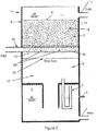
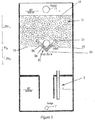
- Figures 2 and 3 illustrate one embodiment of the present invention.
- Figure 2 shows a floating media filter 1 that generally operates as described in reference to Figure 1 .
- media filter 1 includes a diffusor trough 20 extending across the width of filter chamber 3.
- An inlet extension pipe 36 is positioned in diffuser trough 20 and, in this embodiment, is co-extensive with diffusor trough 20.
- Figure 3 is a section view rotated 90° from Figure 2 and better shows the shape and position of diffusor trough 20.
- the distance between upper edge 21 and bottom edge 23 defines a height "H D " of the diffuser trough 20.
- diffuser trough 20 is V-shaped with an upper edge 21, a midpoint 22, and a bottom edge 23.
- the inlet extension pipe 36 includes a series of apertures 38 which discharge influent against the inner surfaces of diffuser trough 20.
- the lower surface 13 of media bed 12 (denoted schematically with a light dashed line in Figures 2 and 3 ) is at about the midpoint 22 of diffuser trough 20.
- Figure 2 shows the diffuser trough 20 extending the entire width of filter housing 2, this is not necessary in all embodiments.
- the diffuser trough may extend less than the entire width of the filter housing.
- many embodiments may not include influent extension pipe 36.
- Figure 3 also suggests how in media bed 12 will have a certain depth or thickness between the upper edge 21 of diffuser trough 20 and the upper surface 16 of media bed 12.
- the Figure 3 embodiment indicates the depth above upper edge 21 is at least three times the trough height H D and more typically between about 5 to 15 times the height H D .
- the portion of the media bed formed above the upper edge 21 of diffuser trough 20 during the filtration stage may be stated in terms of the percentage of the total media bed depth (i.e., the distance between media bed lower surface 13 and upper surface 16) above upper edge 21.
- Figure 3 illustrates approximately 80% of the total depth of media bed 12 forming above upper edge 21.
- at least 50%, 60%, 70%, 90% or 95% of the total depth of the media bed 12 could be formed above upper edge 21 during the filtration stage.
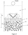
- Figures 4-7 suggests the flow of influent in the filter during both the filtration stage and during backwash and bed reformation. These figures show a modified embodiment where the extension pipe 36 seen in Figures 2 and 3 has been removed. However, the influent flow characteristics described herein relative to the media bed are substantially the same with or without extension pipe 36.
- Figure 4 shows the media beads 14 well into the backwash cycle when the fluid level and the media beads have lowered into the drop chamber 9 below diffuser trough 20. At this point, influent flowing into the diffuser trough 20 quickly fills the trough and spills over onto the dispersed media beads 14. This downward flow of influent will further clean the media beads and tend to push floc particles 60 downward as the fluid level rises.
- Figure 5 shows the rising level of the media beads 14 as inflowing influent continues to raise the fluid level in the filter and continues to produce downward flow currents urging floc particles 60 downward.
- Figure 6 shows the media bed 12 substantially reformed in an early filtration stage subsequent to backwashing.
- the illustrated flow arrows suggests how influent from diffusor trough 20 follows various paths through the media bed to the effluent outlet.
- the flow path to effluent outlet 11 is fairly direct since the biofilm and solids have not yet accumulated sufficiently in the media bed so as to impede fluid flow.
- heavier solids below the media bed are beginning to settle into sludge 61.
- Figure 7 shows the media bed 12 later in the filtration stage.
- Figure 7 suggests how the sludge at the bottom of the filter has become more consolidated.
- floe and other particulate matter 60 begin accumulating in the space between media beads.
- the flow paths through the media bed become more indirect, including some flows 63 near diffuser trough 20 which move downward out the bottom of the bed before re-entering the media bed along the sides of the filter housing.
- the flow velocity is not sufficient to produce substantial eddy currents.
- this media filter design does not tend to entrain solids below the media bed and as a result, does not produce the above described "burp" of "dirty” water as in certain prior art filters.
- Figure 7 also shows the lower surface 13 of media bed 12 is at the bottom edge 23 of diffuser trough 20.
- the lower surface 13 is at the midpoint 22 of diffuser trough 20 (see Figure 3 ) or just below upper edge 21 of diffuser trough 20 or well below the bottom edge 23 of the diffuser trough 20.
- the lower surface 13 of the media bed 12 will be no lower than two times H D below the bottom edge 23 of the diffuser trough 20. However, this is not necessarily a limitation in all embodiments.
- Figures 8a to 8f illustrate a few nonlimiting examples of diffuser trough cross-sectional shapes.
- Figure 8a shows the V-shaped cross-section 30 seen in earlier figures.
- the legs of the "V" seen in Figure 8a are at approximately 45° from the vertical or in other words, the internal angle alpha of the V is 90°.
- the internal angle could be shallower (e.g., anywhere from 90° to 170°) or steeper (e.g., 60°).
- Figure 8a shows the diffuser trough height "H D ,” which in certain embodiments may be between about 3" and about 12," but in other embodiments could be less than or greater than this range depending on the scale and flow requirements of the unit.
- the diffuser trough is configured such that no flow exits the diffuser trough which does not have a vertical component at a point of exiting the diffuser trough.
- Figure 6 shows multiple flow paths 18 exiting diffuser trough 20.
- Flow path 18a is completely vertical, while flow path 18d includes both a vertical and horizontal component. It may be envisioned that even where the internal angle of diffuser trough 20 is 170°, flow path 18d still has some vertically upward component.
- No flow path exiting the diffuser trough is completely horizontal or has any downward component. As suggested in Figure 7 , there may be flow paths through the filter bed which have a downward component, but this is flow which has already exited the diffuser trough and is directed downward by the media bed. At the point of exiting the diffuser trough, all flow has at least some upward component.
- Figure 8b shows a rectangular cross-section 31 while Figure 8c shows a curved or semi-circular shaped cross-section 35.
- Either of cross-sections 31 or 35 may be considered "U-shaped.”
- the Figure 8c cross-section need not be perfectly semicircular (i.e., have a constant radius), but could be parabolic in shape.
- the common feature in the cross-sections 30, 31, and 35 is that they will be oriented in the filter housing in a manner to direct influent flow in a predominantly upward direction into the media bed.
- the cross-sectional area of the trough is adjusted with flowrate such that the trough velocities are low enough to avoid fluidization of the overlying beads.
- Inlet trough horizontal velocities (typically in the range of 0.5 to 3 feet per sec) are also dependent on trough length. It is observed that the trough horizontal velocity falls with length as water moves vertically into the media bed. Longer troughs are less susceptible to momentum induced turbulence at the trough's terminal end, and can tolerate higher initial horizontal trough velocities.
- Figure 8d suggests how the diffuser trough may be a pipe 33 with apertures 38 formed in the upper half of the pipe wall. Again, this will tend to direct influent in an upward orientation toward the media bed. Naturally, the orientation and spacing of the apertures in the upper half of the pipe wall can vary considerably from one embodiment to another.
- Figure 8e shows how the diffuser trough may take an irregular shape or a shape that is a combination of earlier described shapes.
- Figure 8f illustrates that certain embodiments of the diffuser trough will have baffles 25 along its length converting the velocity driven momentum to a localized pressure to encourage vertical flow into the media bed near the baffle's location. It is often advantageous to avoid having the influent stream reach the housing wall opposite inlet 10 with too much velocity.
- baffles have been found to be effective at mitigating high horizontal inlet trough velocities particularly for short troughs that are prone to momentum induced erosion on the terminal end.
- the baffles 25 could take on any number of shapes, including upstanding legs 26.
- Baffles 25 could also take the shape of surface irregularities 27 on the inner wall of the diffuser trough. Virtually any structure along the surface of or in the cross-sectional area of the diffuser trough may serve as baffles as long as the structure slows the velocity of influent (along the length of the diffuser) while increasing the tendency of the influent waters to flow vertically without eroding the media bed.
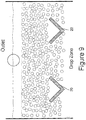
- Figure 9 suggests how different embodiments could have multiple diffuser troughs 20, typically one trough being associated with each influent inlet opening into the filter housing.
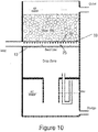
- Figure 10 shows a side sectional view of a media filter having a diffuser trough formed of circular pipe 33 with upwardly directed apertures 38 and baffles 25. The lower surface 13 of the media bed is shown just below circular pipe 33, but lower surface 13 could be as high as just beneath apertures 38 (or perhaps somewhat above the apertures or upper trough edge in certain specialized embodiments).
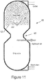
- Figure 11 illustrates an "hour-glass" type floating media filter such as disclosed in U.S. Patent No. 5,232,586 . As explained in U.S.
- the backwashing principle operates through the constricted throat 46 in the filter housing below the media bed and a valve allowing discharge of sufficient liquid to cause a rapid drop of the media bed into the throat.
- the Figure 11 embodiment shows the lower surface 13 of the media bed (during the filtration stage) just above the bottom edge of diffuser trough 20.
- Figure 12 shows two diffuser troughs 20 positioned in a "propeller wash” type of floating media filter such as disclosed in U.S. Patent No. 5,126, 042 .
- the backwash mechanism in propeller wash filters involves at least one propeller 51 positioned in the filter housing and rotated with sufficient speed to disperse the media bed.
- a related backwash mechanism is a "paddle wash" floating media filter such as seen in U.S. Patent No. 5,445,740 .
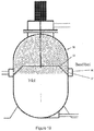
- FIG 13 illustrates a propeller wash type media filter having a peripheral diffuser trough 55.
- peripheral diffuser tough 55 forms a conical frustum shape with an open center portion.
- the filter housing will include the exterior circumferential feed channel 56 which receives influent flow and distributes the influent to a series of filter housing inlet apertures 57, which are also formed around the circumference of the filter housing.
- the open center portion of the peripheral diffuser trough enhances backwashing in propeller wash embodiments allowing the extension of propellers at or below the diffuser trough and lessening interference with the movement of media beads in response to propeller generated dispersion forces.
Landscapes
- Chemical & Material Sciences (AREA)
- Chemical Kinetics & Catalysis (AREA)
- Filtration Of Liquid (AREA)
- Biological Treatment Of Waste Water (AREA)
Claims (12)
- Schwimmender Medienfilter (1) umfassend:a. ein Filtergehäuse (2) mit einem Zulaufeinlass (10) und einem Ablaufauslass (11);b. schwimmende Medien (14), die in dem Gehäuse (2) positioniert sind, um ein Medienbett (12) zu bilden, wenn sich der Filter (1) in einer Filtrationsstufe befindet, wobei das Medienbett (12) eine untere Fläche (13) aufweist;c. eine Diffusorwanne (20), die sich mindestens über einen Teil der Breite des Filtergehäuses erstreckt, wobei die Diffusorwanne (20) eine Oberkante (21) aufweist, wobei die Diffusorwanne:(i) im Filtergehäuse (2) so positioniert ist, dass die untere Fläche (13) des Medienbetts (12), wenn sich der Filter (1) in der Filtrationsstufe befindet, unterhalb der Oberkante (21) der Diffusorwanne (20) liegt; und(ii) eine Form aufweist, die Zulauf in einer überwiegend aufwärtigen Richtung in das Medienbett (12) lenkt, wobei der Zulaufeinlass (10) Zulaufströmung auf einem Weg im Wesentlichen entlang einer inneren Länge der Diffusorwanne (20) lenkt; undd. einen Rückspülmechanismus (15), der während einer Rückspülphase eine Dispersion des Medienbetts (12) verursacht, und der Rückspülmechanismus (15) mindestens einer ist aus der Gruppe bestehend aus:(i) einer Ladekammer (4), die selektiv Luft in das Medienbett (12) abgibt, während gestattet wird, dass Flüssigkeit in die Ladekammer (4) eintreten kann;(ii) einem verengten Hals (46) in dem Filtergehäuse (2) unterhalb des Medienbettes (12) und ein Ventil, das Abgabe von ausreichend Flüssigkeit gestattet, um ein schnelles Fallen des Medienbettes (12) in den Hals (46) zu bewirken;(iii) mindestens einem Propeller (51), der in dem Filtergehäuse (2) positioniert und mit ausreichender Geschwindigkeit gedreht wird, um das Medienbett (12) zu dispergieren; und(iv) mindestens ein Paddel, das in dem Filtergehäuse (2) positioniert und mit ausreichender Geschwindigkeit gedreht wird, um das Medienbett (12) zu rühren.
- Medienfilter nach Anspruch 1, wobei ein Ende der Diffusorwanne (20) an einer Mündung des Zulaufeinlasses (10) positioniert ist.
- Medienfilter nach Anspruch 1, wobei das Medienbett (12) eine Breite aufweist und die Diffusorwanne (20) sich über einen Großteil der Breite des Medienbetts (12) erstreckt.
- Medienfilter nach Anspruch 3, wobei die Diffusorwanne (20) sich im Wesentlichen durch eine gesamte Breite des Medienbetts (12) erstreckt.
- Medienfilter nach Anspruch 1, wobei eine Vielzahl von Leitblechen (25) in der Diffusorwanne (20) positioniert sind, wobei die Leitbleche (25) agieren, um die Zulaufgeschwindigkeit entlang der Länge der Diffusorwanne (20) zu verlangsamen, während sie die Neigung des Zulaufwassers, vertikal zu fließen, erhöhen, ohne das Medienbett (12) zu erodieren.
- Medienfilter nach Anspruch 1, wobei ein Zulaufsrohr (36) sich entlang eines Großteils einer Länge der Diffusorwanne (20) erstreckt.
- Medienfilter nach Anspruch 1, wobei die Diffusorwanne (20) eine Querschnittsform aufweist und die Querschnittsform eins aus der Gruppe beinhaltet, bestehend aus (i) V-förmig (30), (ii) U-förmig, (iii) rechteckig (31) und (iv) kreisförmig.
- Medienfilter nach Anspruch 7, wobei die kreisförmige Diffusorwanne (20) Öffnungen (38) aufweist, die gebildet sind, um den Zulauf in die überwiegend aufwärtige Richtung zu lenken.
- Medienfilter nach Anspruch 1, wobei die Diffusorwanne (20) eine Höhe und einen Mittelpunkt auf der Höhe aufweist, wobei die untere Fläche (13) des Medienbetts (12) auf oder unter dem Mittelpunkt ist.
- Medienfilter nach Anspruch 1, wobei der Rückspülmechanismus (15) Absenken des Medienbetts in eine Fallkammer (9) unterhalb der Diffusorwanne (20) beinhaltet.
- Medienfilter nach Anspruch 10, wobei der Rückspülmechanismus (15) beinhaltet: entweder (i) eine Ladekammer (4), die selektiv Luft in das Medienbett (12) abgibt, während gestattet wird, dass Flüssigkeit in die Ladekammer (4) eintreten kann; oder (ii) einen verengten Hals (46) in dem Filtergehäuse (2) unterhalb des Medienbettes (12) und ein Ventil, das Abgabe von ausreichend Flüssigkeit gestattet, um ein schnelles Fallen des Medienbettes (12) in den Hals (46) zu bewirken;
- Medienfilter nach Anspruch 1, wobei die Diffusorwanne (20) eine Unterkante (23) aufweist und die untere Fläche des Medienbetts an oder unter der Unterkante (23) liegt.
Applications Claiming Priority (2)
| Application Number | Priority Date | Filing Date | Title |
|---|---|---|---|
| US14/730,057 US20160354711A1 (en) | 2015-06-03 | 2015-06-03 | Embedded Influent Diffuser for Floating Media Filter |
| PCT/US2016/035404 WO2016196721A1 (en) | 2015-06-03 | 2016-06-02 | Embedded influent diffuser for floating media filter |
Publications (3)
| Publication Number | Publication Date |
|---|---|
| EP3286148A1 EP3286148A1 (de) | 2018-02-28 |
| EP3286148A4 EP3286148A4 (de) | 2018-06-20 |
| EP3286148B1 true EP3286148B1 (de) | 2020-04-15 |
Family
ID=57441675
Family Applications (1)
| Application Number | Title | Priority Date | Filing Date |
|---|---|---|---|
| EP16804383.4A Active EP3286148B1 (de) | 2015-06-03 | 2016-06-02 | Eingebetteter zuflussdiffusor für filter für schwimmende medien |
Country Status (5)
| Country | Link |
|---|---|
| US (2) | US20160354711A1 (de) |
| EP (1) | EP3286148B1 (de) |
| CA (1) | CA2987930C (de) |
| DK (1) | DK3286148T3 (de) |
| WO (1) | WO2016196721A1 (de) |
Families Citing this family (6)
| Publication number | Priority date | Publication date | Assignee | Title |
|---|---|---|---|---|
| WO2017161381A1 (en) * | 2016-03-18 | 2017-09-21 | Schreiber, Llc | Improved methods for cleaning filtration system media |
| US10913667B2 (en) | 2017-12-08 | 2021-02-09 | Westech Engineering, Inc. | Multi-media clarification systems and methods |
| IL281704B2 (en) * | 2018-09-26 | 2025-08-01 | Netafim Ltd | Liquid filtration system |
| US11219194B1 (en) | 2019-05-10 | 2022-01-11 | Malone Industries, LLC | Aquaponic nutrient generation module |
| CN110354547A (zh) * | 2019-08-13 | 2019-10-22 | 周子翘 | 自清洁过滤装置 |
| CA3252073A1 (en) * | 2022-06-09 | 2023-12-14 | De Nora Water Technologies, LLC | FILTERED WATER COLLECTION SYSTEMS FOR UNDERGROUND DRAINAGE WITH FINNED SCREEN DIFFUSERS |
Family Cites Families (28)
| Publication number | Priority date | Publication date | Assignee | Title |
|---|---|---|---|---|
| BE581152A (de) * | 1958-07-29 | |||
| US3424674A (en) * | 1966-05-10 | 1969-01-28 | Ritter Pfaudler Corp | Upflow filtration of fluids |
| US4011158A (en) * | 1974-04-26 | 1977-03-08 | Liquid Processing Systems, Inc. | Oil-water separation process and apparatus |
| US4076625A (en) * | 1976-01-16 | 1978-02-28 | General Filter Company | Baffle and wash trough assembly for granular-media filters |
| US4246119A (en) * | 1979-02-12 | 1981-01-20 | Alldredge Robert L | Liquid sand filter |
| US4547286A (en) * | 1980-07-22 | 1985-10-15 | Neptune Microfloc, Inc. | Water filtration process and apparatus having upflow filter with buoyant filter media and downflow filter with nonbuoyant filter media |
| JPS5811008A (ja) * | 1981-07-13 | 1983-01-21 | Unitika Ltd | 濾過装置 |
| US4479880A (en) * | 1982-04-21 | 1984-10-30 | Permutit-Boby Limited | Method and apparatus for deflecting granular material away from the outlet of a filtration bed |
| DE3338170C2 (de) * | 1983-10-20 | 1986-07-10 | Preussag Ag, 3000 Hannover Und 1000 Berlin | Verfahren zum Reinigen von Filtermaterial sowie Vorrichtung zur Durchführung des Verfahrens |
| FR2604990B1 (fr) * | 1986-10-01 | 1991-04-05 | Omnium Traitement Valorisa | Procede de purification, par voie biologique, d'eaux residuaires sur lit de materiau granulaire |
| US4861472A (en) * | 1988-07-14 | 1989-08-29 | Smith & Loveless, Inc. | Apparatus for filtration of a suspension |
| US5126042A (en) * | 1991-10-31 | 1992-06-30 | Malone Ronald F | Floating media biofilter |
| US5207905A (en) * | 1992-09-25 | 1993-05-04 | The Graver Company | Baffle assembly for air and water backwash of a media filter |
| US5232586A (en) * | 1992-09-25 | 1993-08-03 | Malone Ronald F | Floating media hourglass biofilter |
| GB9405871D0 (en) * | 1994-03-24 | 1994-05-11 | Thames Water Utilities | Improvements in biological aerated flooded filters |
| JP2975276B2 (ja) | 1994-11-16 | 1999-11-10 | ベスト工業株式会社 | 生物濾過装置用浮上濾材の洗浄方法 |
| JP3271480B2 (ja) * | 1995-06-29 | 2002-04-02 | 株式会社石垣 | 汚水の処理装置 |
| US5932092A (en) * | 1996-06-13 | 1999-08-03 | Hawk; William D. | Filtering apparatus having positively buoyant and negatively buoyant particulate |
| US5770080A (en) * | 1997-04-23 | 1998-06-23 | Malone; Ronald F. | Air charged backwashing bioclarifier |
| US6517724B1 (en) * | 1998-04-16 | 2003-02-11 | Ronald F. Malone | Air charged backwashing bioclarifier |
| US6365044B1 (en) * | 1999-05-21 | 2002-04-02 | Gregory L. Crane | Buoyant media filter with diffuser |
| US6428690B1 (en) * | 2000-09-13 | 2002-08-06 | Tom Tse | Filter module with improved backwash capability |
| US6592751B2 (en) | 2001-09-26 | 2003-07-15 | Council Of Scientific And Industrial Research | Device for treatment of wastewater |
| EP1680365A2 (de) | 2003-10-03 | 2006-07-19 | O.K. Technologies, LLC | Abwasserbehandlungssystem und verfahren |
| BE1016979A6 (nl) * | 2006-02-07 | 2007-11-06 | Vero Bvba | Zelfreinigende filterinrichting voor het zuiveren van water. |
| CN101977853B (zh) * | 2008-01-28 | 2013-07-10 | Ntnu技术转移股份有限公司 | 用于处理废水的方法和装置 |
| TW200949764A (en) | 2008-05-28 | 2009-12-01 | Airlink Technology Co Ltd | Monetary card reading machine, advertisement management system and receipt-printing method |
| US9227863B2 (en) | 2013-11-21 | 2016-01-05 | Ronald F. Malone | Biofiltration with enhanced sludge handling |
-
2015
- 2015-06-03 US US14/730,057 patent/US20160354711A1/en not_active Abandoned
-
2016
- 2016-06-02 CA CA2987930A patent/CA2987930C/en active Active
- 2016-06-02 EP EP16804383.4A patent/EP3286148B1/de active Active
- 2016-06-02 DK DK16804383.4T patent/DK3286148T3/da active
- 2016-06-02 WO PCT/US2016/035404 patent/WO2016196721A1/en not_active Ceased
-
2017
- 2017-12-01 US US15/829,433 patent/US10238997B2/en active Active
Non-Patent Citations (1)
| Title |
|---|
| None * |
Also Published As
| Publication number | Publication date |
|---|---|
| CA2987930A1 (en) | 2016-12-08 |
| US20180133624A1 (en) | 2018-05-17 |
| US10238997B2 (en) | 2019-03-26 |
| US20160354711A1 (en) | 2016-12-08 |
| DK3286148T3 (da) | 2020-06-08 |
| CA2987930C (en) | 2020-09-01 |
| EP3286148A1 (de) | 2018-02-28 |
| WO2016196721A1 (en) | 2016-12-08 |
| EP3286148A4 (de) | 2018-06-20 |
Similar Documents
| Publication | Publication Date | Title |
|---|---|---|
| CA2987930C (en) | Embedded influent diffuser for floating media filter | |
| US7790023B1 (en) | Adjustable floating weir apparatus | |
| KR101455180B1 (ko) | 수류 분산형 가압부상조 | |
| US5122287A (en) | Filtration system | |
| AU2014352938B2 (en) | Biofiltration with enhanced sludge handling | |
| JP6049005B2 (ja) | ろ過装置、そのろ過方法及びろ材の逆洗方法 | |
| US9827512B2 (en) | Embedded influent diffuser for floating media filter | |
| CN102574031A (zh) | 具有多孔过滤介质的高速过滤装置及其反冲洗方法 | |
| CN103097307A (zh) | 包括固体分离装置的净化器、以及用于废水净化的方法 | |
| KR102153224B1 (ko) | 처리효율이 개선된 하폐수처리장치 | |
| NO347337B1 (no) | Filterapparat med et valnøttskallfiltermedium | |
| KR102397619B1 (ko) | 침전물 및 부유물의 처리효율이 개선된 하폐수처리장치 | |
| JPH06190207A (ja) | 濾材濾過装置の水および空気による逆洗用バッフル組立部品 | |
| KR101185811B1 (ko) | 탈기겸용 다회류 고형물 여과장치 | |
| JP6316156B2 (ja) | 沈殿池 | |
| KR100949823B1 (ko) | 수처리장치 | |
| KR102354522B1 (ko) | 스컴 처리효율이 개선된 하폐수처리장치 | |
| KR100955098B1 (ko) | 초기우수의 인 제거용 처리장치 | |
| KR101460958B1 (ko) | 화력발전소 회사장 폐수처리장치 | |
| KR100668420B1 (ko) | 수처리 장치 | |
| KR101586628B1 (ko) | 상·하수 슬러지 분리침전 장치 및 이를 이용한 상·하수 처리 방법 | |
| KR200426877Y1 (ko) | 침전지용 경사판 | |
| KR102397623B1 (ko) | 산소기포를 이용한 부유물의 처리효율이 개선된 하폐수처리장치 | |
| JP2020093240A (ja) | ろ過装置 | |
| JP2003265905A (ja) | 凝集沈殿装置 |
Legal Events
| Date | Code | Title | Description |
|---|---|---|---|
| STAA | Information on the status of an ep patent application or granted ep patent |
Free format text: STATUS: THE INTERNATIONAL PUBLICATION HAS BEEN MADE |
|
| PUAI | Public reference made under article 153(3) epc to a published international application that has entered the european phase |
Free format text: ORIGINAL CODE: 0009012 |
|
| STAA | Information on the status of an ep patent application or granted ep patent |
Free format text: STATUS: REQUEST FOR EXAMINATION WAS MADE |
|
| 17P | Request for examination filed |
Effective date: 20171124 |
|
| AK | Designated contracting states |
Kind code of ref document: A1 Designated state(s): AL AT BE BG CH CY CZ DE DK EE ES FI FR GB GR HR HU IE IS IT LI LT LU LV MC MK MT NL NO PL PT RO RS SE SI SK SM TR |
|
| AX | Request for extension of the european patent |
Extension state: BA ME |
|
| A4 | Supplementary search report drawn up and despatched |
Effective date: 20180523 |
|
| RIC1 | Information provided on ipc code assigned before grant |
Ipc: C02F 3/20 20060101ALI20180516BHEP Ipc: C02F 3/08 20060101ALI20180516BHEP Ipc: C02F 3/06 20060101AFI20180516BHEP Ipc: B01D 24/28 20060101ALI20180516BHEP Ipc: B01D 24/46 20060101ALI20180516BHEP Ipc: C02F 3/10 20060101ALI20180516BHEP |
|
| DAV | Request for validation of the european patent (deleted) | ||
| DAX | Request for extension of the european patent (deleted) | ||
| GRAP | Despatch of communication of intention to grant a patent |
Free format text: ORIGINAL CODE: EPIDOSNIGR1 |
|
| STAA | Information on the status of an ep patent application or granted ep patent |
Free format text: STATUS: GRANT OF PATENT IS INTENDED |
|
| INTG | Intention to grant announced |
Effective date: 20190909 |
|
| RAP1 | Party data changed (applicant data changed or rights of an application transferred) |
Owner name: THE MALONE INDUSTRIES LLC |
|
| RIN1 | Information on inventor provided before grant (corrected) |
Inventor name: MALONE RONALD F. |
|
| GRAS | Grant fee paid |
Free format text: ORIGINAL CODE: EPIDOSNIGR3 |
|
| GRAA | (expected) grant |
Free format text: ORIGINAL CODE: 0009210 |
|
| STAA | Information on the status of an ep patent application or granted ep patent |
Free format text: STATUS: THE PATENT HAS BEEN GRANTED |
|
| RAP1 | Party data changed (applicant data changed or rights of an application transferred) |
Owner name: MALONE INDUSTRIES LLC |
|
| AK | Designated contracting states |
Kind code of ref document: B1 Designated state(s): AL AT BE BG CH CY CZ DE DK EE ES FI FR GB GR HR HU IE IS IT LI LT LU LV MC MK MT NL NO PL PT RO RS SE SI SK SM TR |
|
| REG | Reference to a national code |
Ref country code: CH Ref legal event code: EP |
|
| REG | Reference to a national code |
Ref country code: DE Ref legal event code: R096 Ref document number: 602016034181 Country of ref document: DE |
|
| REG | Reference to a national code |
Ref country code: IE Ref legal event code: FG4D |
|
| REG | Reference to a national code |
Ref country code: AT Ref legal event code: REF Ref document number: 1257084 Country of ref document: AT Kind code of ref document: T Effective date: 20200515 |
|
| REG | Reference to a national code |
Ref country code: DK Ref legal event code: T3 Effective date: 20200603 |
|
| REG | Reference to a national code |
Ref country code: NL Ref legal event code: FP |
|
| REG | Reference to a national code |
Ref country code: NO Ref legal event code: T2 Effective date: 20200415 |
|
| REG | Reference to a national code |
Ref country code: LT Ref legal event code: MG4D |
|
| PG25 | Lapsed in a contracting state [announced via postgrant information from national office to epo] |
Ref country code: PT Free format text: LAPSE BECAUSE OF FAILURE TO SUBMIT A TRANSLATION OF THE DESCRIPTION OR TO PAY THE FEE WITHIN THE PRESCRIBED TIME-LIMIT Effective date: 20200817 Ref country code: FI Free format text: LAPSE BECAUSE OF FAILURE TO SUBMIT A TRANSLATION OF THE DESCRIPTION OR TO PAY THE FEE WITHIN THE PRESCRIBED TIME-LIMIT Effective date: 20200415 Ref country code: LT Free format text: LAPSE BECAUSE OF FAILURE TO SUBMIT A TRANSLATION OF THE DESCRIPTION OR TO PAY THE FEE WITHIN THE PRESCRIBED TIME-LIMIT Effective date: 20200415 Ref country code: SE Free format text: LAPSE BECAUSE OF FAILURE TO SUBMIT A TRANSLATION OF THE DESCRIPTION OR TO PAY THE FEE WITHIN THE PRESCRIBED TIME-LIMIT Effective date: 20200415 Ref country code: IS Free format text: LAPSE BECAUSE OF FAILURE TO SUBMIT A TRANSLATION OF THE DESCRIPTION OR TO PAY THE FEE WITHIN THE PRESCRIBED TIME-LIMIT Effective date: 20200815 Ref country code: GR Free format text: LAPSE BECAUSE OF FAILURE TO SUBMIT A TRANSLATION OF THE DESCRIPTION OR TO PAY THE FEE WITHIN THE PRESCRIBED TIME-LIMIT Effective date: 20200716 |
|
| REG | Reference to a national code |
Ref country code: AT Ref legal event code: MK05 Ref document number: 1257084 Country of ref document: AT Kind code of ref document: T Effective date: 20200415 |
|
| PG25 | Lapsed in a contracting state [announced via postgrant information from national office to epo] |
Ref country code: HR Free format text: LAPSE BECAUSE OF FAILURE TO SUBMIT A TRANSLATION OF THE DESCRIPTION OR TO PAY THE FEE WITHIN THE PRESCRIBED TIME-LIMIT Effective date: 20200415 Ref country code: RS Free format text: LAPSE BECAUSE OF FAILURE TO SUBMIT A TRANSLATION OF THE DESCRIPTION OR TO PAY THE FEE WITHIN THE PRESCRIBED TIME-LIMIT Effective date: 20200415 Ref country code: LV Free format text: LAPSE BECAUSE OF FAILURE TO SUBMIT A TRANSLATION OF THE DESCRIPTION OR TO PAY THE FEE WITHIN THE PRESCRIBED TIME-LIMIT Effective date: 20200415 Ref country code: BG Free format text: LAPSE BECAUSE OF FAILURE TO SUBMIT A TRANSLATION OF THE DESCRIPTION OR TO PAY THE FEE WITHIN THE PRESCRIBED TIME-LIMIT Effective date: 20200715 |
|
| PG25 | Lapsed in a contracting state [announced via postgrant information from national office to epo] |
Ref country code: AL Free format text: LAPSE BECAUSE OF FAILURE TO SUBMIT A TRANSLATION OF THE DESCRIPTION OR TO PAY THE FEE WITHIN THE PRESCRIBED TIME-LIMIT Effective date: 20200415 |
|
| REG | Reference to a national code |
Ref country code: DE Ref legal event code: R097 Ref document number: 602016034181 Country of ref document: DE |
|
| PG25 | Lapsed in a contracting state [announced via postgrant information from national office to epo] |
Ref country code: ES Free format text: LAPSE BECAUSE OF FAILURE TO SUBMIT A TRANSLATION OF THE DESCRIPTION OR TO PAY THE FEE WITHIN THE PRESCRIBED TIME-LIMIT Effective date: 20200415 Ref country code: MC Free format text: LAPSE BECAUSE OF FAILURE TO SUBMIT A TRANSLATION OF THE DESCRIPTION OR TO PAY THE FEE WITHIN THE PRESCRIBED TIME-LIMIT Effective date: 20200415 Ref country code: SM Free format text: LAPSE BECAUSE OF FAILURE TO SUBMIT A TRANSLATION OF THE DESCRIPTION OR TO PAY THE FEE WITHIN THE PRESCRIBED TIME-LIMIT Effective date: 20200415 Ref country code: EE Free format text: LAPSE BECAUSE OF FAILURE TO SUBMIT A TRANSLATION OF THE DESCRIPTION OR TO PAY THE FEE WITHIN THE PRESCRIBED TIME-LIMIT Effective date: 20200415 Ref country code: RO Free format text: LAPSE BECAUSE OF FAILURE TO SUBMIT A TRANSLATION OF THE DESCRIPTION OR TO PAY THE FEE WITHIN THE PRESCRIBED TIME-LIMIT Effective date: 20200415 Ref country code: IT Free format text: LAPSE BECAUSE OF FAILURE TO SUBMIT A TRANSLATION OF THE DESCRIPTION OR TO PAY THE FEE WITHIN THE PRESCRIBED TIME-LIMIT Effective date: 20200415 Ref country code: AT Free format text: LAPSE BECAUSE OF FAILURE TO SUBMIT A TRANSLATION OF THE DESCRIPTION OR TO PAY THE FEE WITHIN THE PRESCRIBED TIME-LIMIT Effective date: 20200415 Ref country code: CZ Free format text: LAPSE BECAUSE OF FAILURE TO SUBMIT A TRANSLATION OF THE DESCRIPTION OR TO PAY THE FEE WITHIN THE PRESCRIBED TIME-LIMIT Effective date: 20200415 |
|
| REG | Reference to a national code |
Ref country code: CH Ref legal event code: PL |
|
| PLBE | No opposition filed within time limit |
Free format text: ORIGINAL CODE: 0009261 |
|
| STAA | Information on the status of an ep patent application or granted ep patent |
Free format text: STATUS: NO OPPOSITION FILED WITHIN TIME LIMIT |
|
| PG25 | Lapsed in a contracting state [announced via postgrant information from national office to epo] |
Ref country code: PL Free format text: LAPSE BECAUSE OF FAILURE TO SUBMIT A TRANSLATION OF THE DESCRIPTION OR TO PAY THE FEE WITHIN THE PRESCRIBED TIME-LIMIT Effective date: 20200415 Ref country code: SK Free format text: LAPSE BECAUSE OF FAILURE TO SUBMIT A TRANSLATION OF THE DESCRIPTION OR TO PAY THE FEE WITHIN THE PRESCRIBED TIME-LIMIT Effective date: 20200415 |
|
| 26N | No opposition filed |
Effective date: 20210118 |
|
| PG25 | Lapsed in a contracting state [announced via postgrant information from national office to epo] |
Ref country code: LU Free format text: LAPSE BECAUSE OF NON-PAYMENT OF DUE FEES Effective date: 20200602 |
|
| REG | Reference to a national code |
Ref country code: BE Ref legal event code: MM Effective date: 20200630 |
|
| PG25 | Lapsed in a contracting state [announced via postgrant information from national office to epo] |
Ref country code: IE Free format text: LAPSE BECAUSE OF NON-PAYMENT OF DUE FEES Effective date: 20200602 Ref country code: LI Free format text: LAPSE BECAUSE OF NON-PAYMENT OF DUE FEES Effective date: 20200630 Ref country code: CH Free format text: LAPSE BECAUSE OF NON-PAYMENT OF DUE FEES Effective date: 20200630 |
|
| PG25 | Lapsed in a contracting state [announced via postgrant information from national office to epo] |
Ref country code: BE Free format text: LAPSE BECAUSE OF NON-PAYMENT OF DUE FEES Effective date: 20200630 Ref country code: SI Free format text: LAPSE BECAUSE OF FAILURE TO SUBMIT A TRANSLATION OF THE DESCRIPTION OR TO PAY THE FEE WITHIN THE PRESCRIBED TIME-LIMIT Effective date: 20200415 |
|
| PG25 | Lapsed in a contracting state [announced via postgrant information from national office to epo] |
Ref country code: TR Free format text: LAPSE BECAUSE OF FAILURE TO SUBMIT A TRANSLATION OF THE DESCRIPTION OR TO PAY THE FEE WITHIN THE PRESCRIBED TIME-LIMIT Effective date: 20200415 Ref country code: MT Free format text: LAPSE BECAUSE OF FAILURE TO SUBMIT A TRANSLATION OF THE DESCRIPTION OR TO PAY THE FEE WITHIN THE PRESCRIBED TIME-LIMIT Effective date: 20200415 Ref country code: CY Free format text: LAPSE BECAUSE OF FAILURE TO SUBMIT A TRANSLATION OF THE DESCRIPTION OR TO PAY THE FEE WITHIN THE PRESCRIBED TIME-LIMIT Effective date: 20200415 |
|
| PG25 | Lapsed in a contracting state [announced via postgrant information from national office to epo] |
Ref country code: MK Free format text: LAPSE BECAUSE OF FAILURE TO SUBMIT A TRANSLATION OF THE DESCRIPTION OR TO PAY THE FEE WITHIN THE PRESCRIBED TIME-LIMIT Effective date: 20200415 |
|
| PGFP | Annual fee paid to national office [announced via postgrant information from national office to epo] |
Ref country code: GB Payment date: 20260629 Year of fee payment: 11 Ref country code: DK Payment date: 20260625 Year of fee payment: 11 |
|
| PGFP | Annual fee paid to national office [announced via postgrant information from national office to epo] |
Ref country code: DE Payment date: 20260629 Year of fee payment: 11 |
|
| PGFP | Annual fee paid to national office [announced via postgrant information from national office to epo] |
Ref country code: NO Payment date: 20260629 Year of fee payment: 11 |
|
| PGFP | Annual fee paid to national office [announced via postgrant information from national office to epo] |
Ref country code: NL Payment date: 20260627 Year of fee payment: 11 |
|
| PGFP | Annual fee paid to national office [announced via postgrant information from national office to epo] |
Ref country code: FR Payment date: 20260625 Year of fee payment: 11 |