EP3286400B1 - Versetzte wellenlagerbaugruppe - Google Patents
Versetzte wellenlagerbaugruppe Download PDFInfo
- Publication number
- EP3286400B1 EP3286400B1 EP16783995.0A EP16783995A EP3286400B1 EP 3286400 B1 EP3286400 B1 EP 3286400B1 EP 16783995 A EP16783995 A EP 16783995A EP 3286400 B1 EP3286400 B1 EP 3286400B1
- Authority
- EP
- European Patent Office
- Prior art keywords
- bearing
- housing
- centerline
- shaft
- offset
- Prior art date
- Legal status (The legal status is an assumption and is not a legal conclusion. Google has not performed a legal analysis and makes no representation as to the accuracy of the status listed.)
- Active
Links
Images



Classifications
-
- E—FIXED CONSTRUCTIONS
- E21—EARTH OR ROCK DRILLING; MINING
- E21B—EARTH OR ROCK DRILLING; OBTAINING OIL, GAS, WATER, SOLUBLE OR MELTABLE MATERIALS OR A SLURRY OF MINERALS FROM WELLS
- E21B4/00—Drives for drilling, used in the borehole
- E21B4/003—Bearing, sealing, lubricating details
-
- E—FIXED CONSTRUCTIONS
- E21—EARTH OR ROCK DRILLING; MINING
- E21B—EARTH OR ROCK DRILLING; OBTAINING OIL, GAS, WATER, SOLUBLE OR MELTABLE MATERIALS OR A SLURRY OF MINERALS FROM WELLS
- E21B23/00—Apparatus for displacing, setting, locking, releasing or removing tools, packers or the like in boreholes or wells
- E21B23/04—Apparatus for displacing, setting, locking, releasing or removing tools, packers or the like in boreholes or wells operated by fluid means, e.g. actuated by explosion
- E21B23/0419—Apparatus for displacing, setting, locking, releasing or removing tools, packers or the like in boreholes or wells operated by fluid means, e.g. actuated by explosion using down-hole motor and pump arrangements for generating hydraulic pressure
-
- E—FIXED CONSTRUCTIONS
- E21—EARTH OR ROCK DRILLING; MINING
- E21B—EARTH OR ROCK DRILLING; OBTAINING OIL, GAS, WATER, SOLUBLE OR MELTABLE MATERIALS OR A SLURRY OF MINERALS FROM WELLS
- E21B7/00—Special methods or apparatus for drilling
- E21B7/04—Directional drilling
- E21B7/06—Deflecting the direction of boreholes
- E21B7/067—Deflecting the direction of boreholes with means for locking sections of a pipe or of a guide for a shaft in angular relation, e.g. adjustable bent sub
-
- E—FIXED CONSTRUCTIONS
- E21—EARTH OR ROCK DRILLING; MINING
- E21B—EARTH OR ROCK DRILLING; OBTAINING OIL, GAS, WATER, SOLUBLE OR MELTABLE MATERIALS OR A SLURRY OF MINERALS FROM WELLS
- E21B7/00—Special methods or apparatus for drilling
- E21B7/04—Directional drilling
- E21B7/06—Deflecting the direction of boreholes
- E21B7/068—Deflecting the direction of boreholes drilled by a down-hole drilling motor
-
- F—MECHANICAL ENGINEERING; LIGHTING; HEATING; WEAPONS; BLASTING
- F16—ENGINEERING ELEMENTS AND UNITS; GENERAL MEASURES FOR PRODUCING AND MAINTAINING EFFECTIVE FUNCTIONING OF MACHINES OR INSTALLATIONS; THERMAL INSULATION IN GENERAL
- F16C—SHAFTS; FLEXIBLE SHAFTS; ELEMENTS OR CRANKSHAFT MECHANISMS; ROTARY BODIES OTHER THAN GEARING ELEMENTS; BEARINGS
- F16C17/00—Sliding-contact bearings for exclusively rotary movement
- F16C17/10—Sliding-contact bearings for exclusively rotary movement for both radial and axial load
-
- F—MECHANICAL ENGINEERING; LIGHTING; HEATING; WEAPONS; BLASTING
- F16—ENGINEERING ELEMENTS AND UNITS; GENERAL MEASURES FOR PRODUCING AND MAINTAINING EFFECTIVE FUNCTIONING OF MACHINES OR INSTALLATIONS; THERMAL INSULATION IN GENERAL
- F16C—SHAFTS; FLEXIBLE SHAFTS; ELEMENTS OR CRANKSHAFT MECHANISMS; ROTARY BODIES OTHER THAN GEARING ELEMENTS; BEARINGS
- F16C17/00—Sliding-contact bearings for exclusively rotary movement
- F16C17/10—Sliding-contact bearings for exclusively rotary movement for both radial and axial load
- F16C17/102—Sliding-contact bearings for exclusively rotary movement for both radial and axial load with grooves in the bearing surface to generate hydrodynamic pressure
- F16C17/105—Sliding-contact bearings for exclusively rotary movement for both radial and axial load with grooves in the bearing surface to generate hydrodynamic pressure with at least one bearing surface providing angular contact, e.g. conical or spherical bearing surfaces
-
- F—MECHANICAL ENGINEERING; LIGHTING; HEATING; WEAPONS; BLASTING
- F16—ENGINEERING ELEMENTS AND UNITS; GENERAL MEASURES FOR PRODUCING AND MAINTAINING EFFECTIVE FUNCTIONING OF MACHINES OR INSTALLATIONS; THERMAL INSULATION IN GENERAL
- F16C—SHAFTS; FLEXIBLE SHAFTS; ELEMENTS OR CRANKSHAFT MECHANISMS; ROTARY BODIES OTHER THAN GEARING ELEMENTS; BEARINGS
- F16C23/00—Bearings for exclusively rotary movement adjustable for aligning or positioning
- F16C23/10—Bearings, parts of which are eccentrically adjustable with respect to each other
-
- F—MECHANICAL ENGINEERING; LIGHTING; HEATING; WEAPONS; BLASTING
- F16—ENGINEERING ELEMENTS AND UNITS; GENERAL MEASURES FOR PRODUCING AND MAINTAINING EFFECTIVE FUNCTIONING OF MACHINES OR INSTALLATIONS; THERMAL INSULATION IN GENERAL
- F16C—SHAFTS; FLEXIBLE SHAFTS; ELEMENTS OR CRANKSHAFT MECHANISMS; ROTARY BODIES OTHER THAN GEARING ELEMENTS; BEARINGS
- F16C33/00—Parts of bearings; Special methods for making bearings or parts thereof
- F16C33/02—Parts of sliding-contact bearings
- F16C33/04—Brasses; Bushes; Linings
- F16C33/043—Sliding surface consisting mainly of ceramics, cermets or hard carbon, e.g. diamond like carbon [DLC]
-
- F—MECHANICAL ENGINEERING; LIGHTING; HEATING; WEAPONS; BLASTING
- F16—ENGINEERING ELEMENTS AND UNITS; GENERAL MEASURES FOR PRODUCING AND MAINTAINING EFFECTIVE FUNCTIONING OF MACHINES OR INSTALLATIONS; THERMAL INSULATION IN GENERAL
- F16C—SHAFTS; FLEXIBLE SHAFTS; ELEMENTS OR CRANKSHAFT MECHANISMS; ROTARY BODIES OTHER THAN GEARING ELEMENTS; BEARINGS
- F16C33/00—Parts of bearings; Special methods for making bearings or parts thereof
- F16C33/02—Parts of sliding-contact bearings
- F16C33/04—Brasses; Bushes; Linings
- F16C33/26—Brasses; Bushes; Linings made from wire coils; made from a number of discs, rings, rods, or other members
-
- F—MECHANICAL ENGINEERING; LIGHTING; HEATING; WEAPONS; BLASTING
- F16—ENGINEERING ELEMENTS AND UNITS; GENERAL MEASURES FOR PRODUCING AND MAINTAINING EFFECTIVE FUNCTIONING OF MACHINES OR INSTALLATIONS; THERMAL INSULATION IN GENERAL
- F16C—SHAFTS; FLEXIBLE SHAFTS; ELEMENTS OR CRANKSHAFT MECHANISMS; ROTARY BODIES OTHER THAN GEARING ELEMENTS; BEARINGS
- F16C23/00—Bearings for exclusively rotary movement adjustable for aligning or positioning
- F16C23/02—Sliding-contact bearings
- F16C23/04—Sliding-contact bearings self-adjusting
- F16C23/043—Sliding-contact bearings self-adjusting with spherical surfaces, e.g. spherical plain bearings
-
- F—MECHANICAL ENGINEERING; LIGHTING; HEATING; WEAPONS; BLASTING
- F16—ENGINEERING ELEMENTS AND UNITS; GENERAL MEASURES FOR PRODUCING AND MAINTAINING EFFECTIVE FUNCTIONING OF MACHINES OR INSTALLATIONS; THERMAL INSULATION IN GENERAL
- F16C—SHAFTS; FLEXIBLE SHAFTS; ELEMENTS OR CRANKSHAFT MECHANISMS; ROTARY BODIES OTHER THAN GEARING ELEMENTS; BEARINGS
- F16C2352/00—Apparatus for drilling
Definitions
- the present disclosure relates generally to bearing assemblies, and specifically to bearing assemblies for directional drilling.
- the drill bit When drilling a wellbore, the drill bit may be turned by a rotation of the drill string or by a downhole motor.
- the downhole motor may be used to rotate the drill bit while the drill string is stationary.
- the bottom hole assembly located at the end of the drill string, may include the downhole motor, the drill bit, and a bearing section.
- the bearing section couples between the motor sub and the drill bit and houses the drive shaft which couples between the drill bit and the downhole motor.
- the bearing section couples to the drive shaft through one or more bearings to allow rotation of the drive shaft as the bearing section remains generally stationary within the wellbore.
- the present invention provides for an offset shaft bearing assembly for a downhole tool according to the claims.
- the present disclosure also provides for a method according to the respective claims and defined by them.
- a bottom hole assembly may include offset shaft bearing assembly 100.
- Offset shaft bearing assembly 100 may include outer housing 101.
- Outer housing 101 may be generally tubular.
- Outer housing 101 may include one or more tubular subunits or subs to, for example and without limitation, facilitate assembly of offset shaft bearing assembly 100.
- One having ordinary skill in the art with the benefit of this disclosure will understand that the specific sub arrangement of outer housing 101 depicted and described herein is merely exemplary and is not intended to limit the scope of this disclosure.
- Outer housing 101 may include coupler 103.
- Coupler 103 may be adapted to couple to additional subs (not shown) of the BHA, including, for example and without limitation, a housing of a downhole motor such as a mud motor. Coupler 103 may rigidly couple outer housing 101 to the rest of the BHA. In some embodiments, outer housing 101 may be prevented from rotating within the wellbore. In some embodiments, outer housing 101 may include one or more external stabilizers 102 to, for example and without limitation, position offset shaft bearing assembly 100 within the wellbore. External stabilizers 102 may be, for example and without limitation, one or more radial protrusions, depicted in cross section in FIGS. 1A , 2A . External stabilizers 102 may be positioned and have a selected diameter depending on the wellbore in which offset shaft bearing assembly 100 is to be used.
- Offset shaft bearing assembly 100 may further include drive shaft 105.
- Drive shaft 105 extends through inner bore 107 of outer housing 101.
- Drive shaft 105 may include shaft coupler 109.
- Shaft coupler 109 may mechanically couple to the output shaft of a downhole motor at a second end of drive shaft 105.
- shaft coupler 109 may mechanically couple to the output shaft of a mud motor through a transmission shaft.
- shaft coupler 109 may include a constant velocity joint adapted to allow the output shaft of the motor to couple to drive shaft 105.
- Drive shaft 105 may further include bit coupler 110 at a first end of drive shaft 105.
- Bit coupler 110 may mechanically couple to a drill bit by, for example and without limitation, a box and pin joint.
- drive shaft 105 may be coupled to outer housing 101 by one or more bearings 111a, b.
- bearings 111a, b may be radiused conical bearings, also referred to in the art as angle, taper, or cup/cone bearings.
- Radiused conical bearings, as depicted in FIG. 3 may include cup portion 113 and cone portion 115. Cup portion 113 and cone portion 115 may be generally annular and adapted to contact at bearing surfaces 117 and 119 respectively.
- Bearing surfaces 117 and 119 may be generally frustoconical in shape, allowing bearings 111a, b to resist longitudinal or thrust loading as well as radial loading between cup portion 113 and cone portion 115 while allowing relative rotation between cup portion 113 and cone portion 115.
- Bearing surfaces 117, 119 may be radiused such that bearing surfaces 117, 119 are in contact. In some embodiments, bearing surfaces 117, 119 may remain in contact despite angular misalignment between cup portion 113 and cone portion 115, allowing bearings 111a, b to function with an angle between drive shaft 105 and outer housing 101.
- bearings 111a, b may thus act as both thrust and radial bearings.
- bearing surfaces 117 and 119 may include one or more bearing elements 121 adapted to reduce wear on cup portion 113 and cone portion 115.
- bearing elements 121 may be polycrystalline diamond compacts.
- bearings 111a, b may include generally cylindrical outer surface 123 and generally cylindrical inner surface 125. Outer surface 123 may serve to couple between or align bearings 111a, b with outer housing 101 and inner surface 125 may serve to couple between or align bearings 111a, b with drive shaft 105.
- bearing surfaces 117 and 119 may be curved or radiused such that bearing surfaces 117 and 119 remain in contact despite angular misalignment between cup portion 113 and cone portion 115, thus allowing rotation of drive shaft 105 relative to outer housing 101 while drive shaft 105 is at an angle thereto.
- each bearing 111a, b may be coupled to outer housing 101 and the cone portion 115 may be coupled to drive shaft 105.
- cup portions 113 may instead be coupled to drive shaft 105 and cone portions 115 may be coupled to outer housing 101 without deviating from the scope of this disclosure.
- Bearings 111a, b may be positioned such that they retain drive shaft 105 both longitudinally and radially. In some embodiments, bearings 111a, b may thus be oriented in opposing directions. Although described herein as utilizing two bearings 111a, b, one having ordinary skill in the art with the benefit of this disclosure will understand that any number of bearings 111a, b may be utilized without deviating from the scope of this disclosure.
- bearings 111a, b may be offset from the housing centerline ⁇ of outer housing 101, designated as ⁇ .
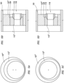
- FIGS. 1A , 2A depict bearing 111b as being offset ( FIGS. 1D , 2D ) and bearing 111a as being centered ( FIGS. 1B , 2B ).
- bearings 111a, b or bearing 111a alone may be offset without deviating from the scope of the present disclosure.
- bearing 111b may be formed eccentrically.
- outer surface 123 of bearing 111b may be parallel to but nonconcentric with inner surface 125.
- bearing mount 127 may be concentric with the housing centerline ⁇ of outer housing 101.
- outer surface 123' of bearing 111b may be concentric with inner surface 125'.
- Bearings 111b may be coupled to outer housing 101 by offset bearing mount 127'.
- Offset bearing mount 127' may be formed eccentrically such that the centerline of bearing 111b is offset from housing centerline ⁇ of outer housing 101, thus positioning drive shaft 105 (defining shaft centerline ⁇ ) at an angle to housing centerline ⁇ .
- Bearings 111a, b may thus be formed as standard radiused conical bearings including no eccentricity.
- offset bearing mount 127' may be formed such that inner surface 128' is parallel to but nonconcentric with outer surface 130'.
- offset bearing mount 127' may be formed such that inner surface 128' is at an angle to outer surface 130'.
- drive shaft 105 having shaft centerline ⁇ , extends at an angle to housing centerline ⁇ of outer housing 101.
- the drill bit coupled to drive shaft 105 is pointed in the direction of shaft centerline ⁇ , causing the wellbore drilled thereby to deviate or build in the direction of offset of shaft centerline ⁇ from housing centerline ⁇ , referred to herein as the build direction.
- the angle between housing centerline ⁇ and shaft centerline ⁇ may be between 0.1° and 3°, between 0.3° and 2°, or between 0.4° and 0.6°.
- both bearing 111b and bearing mount 127" may be offset.
- cup portion 113" may be offset as previously discussed.
- cone portion 115 may be coupled to bearing mount 127" and may be the offset portion of bearing 111b.
- cup portion 113" may be rotatably positionable within bearing mount 127".
- one or more rotational retention features including, for example and without limitation, cup portion 113" may include an external spline and bearing mount 127" may include an internal spline at coupling interface 124 which may, for example, allow cup portion 113" to be engaged into bearing mount 127" in various rotational positions.
- cup portion 113" By positioning cup portion 113" such that the offset aligns with the offset of bearing mount 127" as depicted in FIGS. 5A, 5B , the angle of drive shaft 105 as previously discussed may be increased.
- the angle of drive shaft 105 may be decreased or eliminated.
- the angle of drive shaft 105 may be varied.
- bearing mount 127" and cup portion 113" may be rotatable relative to outer housing 101.
- one or both of bearing mount 127" and cup portion 113" may be mechanically coupled to one or more motors such as, for example and without limitation, electric motors, gearing systems, ratcheting valve systems, ramps, solenoids, pistons, or other power transmission mechanisms.
- the motor or motors may rotate bearing mount 127" and/or cup portion 113" to, for example and without limitation, vary the angle of drive shaft 105.
- the motor or motors may be operable while offset shaft bearing assembly 100 is positioned in the wellbore.
- shaft centerline ⁇ may intersect housing centerline ⁇ of outer housing 101 at crossover point 129.
- crossover point 129 may be positioned at an end of offset shaft bearing assembly near or at bit coupler 110. By locating crossover point 129 near the drill bit, the drill bit may remain generally centered during a rotation of the drill string. By reducing eccentricity of the drill bit, wobble or eccentric movement during rotation of the drill string may be reduced. Reducing wobble may, for example and without limitation, reduce damage to the wellbore or drill bit.
- outer housing 101 may be capable of rotating at a higher rate than a drill string utilizing a bent sub to achieve the build angle as, for example and without limitation, eccentric rotation of bent components is eliminated, reducing damage to the wellbore and stresses imposed on the drill string.
- rotation of the drill string may be achieved utilizing less power and lower pressure to run a mud pump to power drive shaft 105.
- rotation rates nearly equal to straight bottom hole assemblies may be achieved without additional damage to the drill string or wellbore.
- the drill string including offset shaft bearing assembly 100 may be capable of reliable rotation up to 250 RPM.
- inner bore 107 of outer housing 101 may be angled relative to housing centerline ⁇ of outer housing 101 such that inner bore 107 is concentric with shaft centerline ⁇ .
- offset shaft bearing assembly 100 may include mandrel catcher 131 to, for example and without limitation, prevent drive shaft 105 from exiting outer housing 101.
- flow path 133 may be formed between drive shaft 105 and outer housing 101.
- flow restrictor 135 may be positioned between drive shaft 105 and outer housing 101 to, for example and without limitation, limit the flow of fluid between drive shaft 105 and outer housing 101 and reduce or prevent washout of components of offset shaft bearing assembly 100 caused by high speed fluid flow through flowpath 133.
- bearings 111a, 111b may, as depicted in FIG. 3 , include parent surface 122 between bearing elements 121.
- Parent surface 122 may, for example and without limitation, be formed from a material softer than bearing elements 121 and may be positioned to erode when exposed to high velocity fluid, avoiding damage to bearing elements 121.
- parent surface 122 may be hardened by, for example and without limitation, a carbide coating.
- preload spacer 137 may be positioned between preloading shoulders 139, 141 positioned on outer housing 101 and drive shaft 105 respectively. Preload spacer 137 may be positioned to preload bearings 111a, b. As an example, because of the weight on the drill bit, the bearing providing thrust resistance in the direction of the drill bit, depicted in FIGS. 1A , 2A as bearing 111b, must resist a greater thrust force than the other bearing (111a). Preload spacer 137 may generally equalize loading between bearings 111a, b preventing, for example and without limitation, uneven wear between bearings 111a, b and uneven frictional characteristics.
- preload spacer 137 and preloading shoulders 139, 141 may be positioned between any components of offset shaft bearing assembly 100 capable of inducing the preloading as described without deviating from the scope of this disclosure.
- Other exemplary locations at which preload spacer 137 may be positioned include, for example and without limitation, between outer housing 101 and bearings 111a, b (denoted as 137' in FIG. 1A ) or between drive shaft 105 and bearings 111a, b (denoted as 137" in FIG. 1A ).
- offset shaft bearing assembly 100 may include an indication of the offset direction of shaft centerline ⁇ from housing centerline ⁇ . The indication may, for example and without limitation, allow an operator to identify the build direction or toolface of the BHA including offset shaft bearing assembly 100. In some embodiments, offset shaft bearing assembly 100 may include one or more scribe lines 142.
- the build rate of offset shaft bearing assembly 200 may be further increased by positioning a bent housing as understood in the art between the motor and offset shaft bearing assembly.
- offset shaft bearing assembly 200 may include bent outer housing 201.
- Bent outer housing 201 may, for example and without limitation, include bent portion 203.
- Bent portion 203 may be adapted to couple to the rest of the drill string to, for example and without limitation, further increase the build angle of drive shaft 105.
- bent portion 203 may include a bend angle between 0.1° and 5°, between 0.3° and 3°, or between 0.4° and 1°.
- FIG. 4A depicts the centerline of drill string as drill string centerline ⁇ , offset from both housing centerline ⁇ and shaft centerline ⁇ . Bent portion 203 may be fixed or adjustable.
- bent outer housing 201 may couple to inner housing 205.
- Inner housing 205 may include inner bore 207 formed at an angle to housing centerline ⁇ as previously described which defines shaft centerline ⁇ .
- Inner housing 205 may be coupled to bearings 211a, b.
- inner housing 205 may couple to bent outer housing 201 by threaded coupler 209.
- timing spacer 213 may be positioned between bent outer housing 201 and inner housing 205 in threaded coupler 209.
- timing spacer 213 may be a ring or washer of a specific width such that when inner housing 205 is coupled onto bent outer housing 201, the bend of bent outer housing 201 and build angle of inner housing 205 are aligned while maintaining a tight threaded coupling therebetween.
- timing spacer 213 may be one or more annular spacers, bushings, washers, or Belleville springs.
- offset shaft bearing assembly 200 may include bearing pad 215.
- Bearing pad 215 may be positioned on the exterior of bent outer housing 201 at a location opposite the toolface of offset shaft bearing assembly 200. Bearing pad 215 may, for example and without limitation, prevent rotation of offset shaft bearing assembly 200 within the wellbore and reduce wear on offset shaft bearing assembly 200 during drilling operations.
- inner bore 207 may be formed in inner housing 205.
- Inner bore 207 may be formed by any method including, for example and without limitation, milling, boring, turning, or combinations thereof.
- Inner bore 207 may be formed at an angle to the housing centerline ⁇ of inner housing 205 to form shaft centerline ⁇ as discussed hereinabove.
- Drive shaft 105 and bearings 211a, b may be coupled to inner housing 205.
- the same bearings 211a, b may be utilized despite the selected angle between housing centerline ⁇ and shaft centerline ⁇ .
- Inner housing 205 may then be coupled to an outer housing, either a straight outer housing such as outer housing 101 as depicted in FIGS. 1A , 2A or bent outer housing 201 as depicted in FIGS. 4A , B.
- inner housing 205 may be coupled to bent outer housing 201 utilizing a threaded coupler 209 having timing spacer 213 as described hereinabove. Timing spacer 213 may be selected such that its width allows the bend of bent outer housing 201 to align with the angle between housing centerline ⁇ and shaft centerline ⁇ .
- offset shaft bearing assembly 100 may include bit box stabilizer 102".
- Bit box stabilizer 102" may be positioned on an outer surface of offset shaft bearing assembly 100 at bit coupler 110.
- bit box stabilizer 102" may, for example and without limitation, position offset shaft bearing assembly 100 within the wellbore.
- Bit box stabilizer 102" may be, for example and without limitation, one or more radial protrusions.
- Bit box stabilizer 102" may have a selected diameter depending on the wellbore in which offset shaft bearing assembly 100 is to be used.
- external stabilizers 102 may include one or more pistons 102'.
- Pistons 102' may, for example and without limitation, be extendable from an outer surface of external stabilizers 102. Pistons 102' may, in some embodiments, be driven hydraulically.
- pistons 102' may be controlled by one or more valves (not shown) and may extend from offset shaft bearing assembly 100 to contact the surrounding wellbore. In some embodiments, pistons 102' may be used to vary the angle between centerline ⁇ of outer housing 101 and a centerline of the wellbore.
Landscapes
- Engineering & Computer Science (AREA)
- General Engineering & Computer Science (AREA)
- Life Sciences & Earth Sciences (AREA)
- Mining & Mineral Resources (AREA)
- Geology (AREA)
- Mechanical Engineering (AREA)
- Physics & Mathematics (AREA)
- Fluid Mechanics (AREA)
- Environmental & Geological Engineering (AREA)
- General Life Sciences & Earth Sciences (AREA)
- Geochemistry & Mineralogy (AREA)
- Chemical & Material Sciences (AREA)
- Ceramic Engineering (AREA)
- Mounting Of Bearings Or Others (AREA)
- Ocean & Marine Engineering (AREA)
- Rotary Pumps (AREA)
- Motor Or Generator Frames (AREA)
Claims (14)
- Versetzte Wellenlageranordnung (100, 200) für ein Bohrlochwerkzeug, umfassend:ein Außengehäuse (101, 201), wobei das Außengehäuse (101, 201) eine Gehäusemittellinie aufweist;eine Antriebswelle (105), wobei sich die Antriebswelle (105) durch das Außengehäuse (101 201) erstreckt, wobei die Antriebswelle (105) im Allgemeinen rohrförmig ist und eine Wellenmittellinie aufweist; undzwei oder mehr gerundete konische Lager (111a, 111b, 211a, 211b), die zum Koppeln der Antriebswelle (105) mit dem Außengehäuse (101, 201) positioniert sind, wobei jedes gerundete konische Lager (111a, 111b, 211a, 211b) aufweist:eine äußere Oberfläche (123, 123'), wobei die äußere Oberfläche (123, 123') im Allgemeinen zylindrisch ist, wobei die äußere Oberfläche (123, 123') mit dem Außengehäuse (101, 201) gekoppelt ist und mit der Gehäusemittellinie ausgerichtet ist;eine innere Oberfläche (125, 125'), wobei die innere Oberfläche (125, 125') im Allgemeinen zylindrisch ist, wobei die innere Oberfläche (125, 125') mit der Antriebswelle (105) gekoppelt und mit der Wellenmittellinie ausgerichtet ist, so dass die innere Oberfläche (125, 125') und die äußere Oberfläche (123, 123') konzentrisch sind;eine erste Lageroberfläche (117, 119), wobei die erste Lageroberfläche (117, 119) mit der äußeren Oberfläche (123, 123') des gerundeten konischen Lagers (111a, 111b, 211a, 211b) gekoppelt ist; undeine zweite Lageroberfläche (117, 119), wobei die zweite Lageroberfläche (117, 119) mit der Innenoberfläche (125, 125') des gerundeten konischen Lagers (Illa, 111b, 211a, 211b) gekoppelt ist, wobei die Lageroberflächen (117, 119) so gerundet sind, dass die Lageroberflächen (117, 119) trotz einer Winkelfehlausrichtung zwischen der äußeren Oberfläche (123, 123') und der inneren Oberfläche (125, 125') in Kontakt bleiben;dadurch gekennzeichnet, dassdie innere Oberfläche (125, 125') mindestens eines gerundeten konischen Lagers (111a, 111b, 211a, 211b) von der Gehäusemittellinie in einer Richtung senkrecht zur Gehäusemittellinie versetzt ist, so dass die Wellenmittellinie einen Winkel mit der Gehäusemittellinie bildet.
- Versetzte Wellenlageranordnung (100, 200) nach Anspruch 1, wobei die Antriebswelle (105) eine Meißelkupplung (110) umfasst, um einen Bohrmeißel mechanisch mit einem ersten Ende der Antriebswelle (105) zu koppeln, und eine Wellenkupplung (109), um eine Ausgangswelle eines Schlammmotors mechanisch mit einem zweiten Ende der Antriebswelle (105) zu koppeln; wobei die Wellenkupplung (109) optional ein Gleichlaufgelenk umfasst.
- Versetzte Wellenlageranordnung (100, 200) nach Anspruch 1, wobei jedes gerundete konische Lager (111a, 111b, 211a, 211b) einen Schalenabschnitt (113, 113") und einen Konusabschnitt (115) einschließt, wobei der Schalenabschnitt (113, 113") und der Konusabschnitt (115) an der gerundeten Lageroberfläche (117, 119) in Kontakt kommen.
- Versetzte Wellenlageranordnung (100, 200) nach Anspruch 3, wobei
der Schalenabschnitt (113, 113") und der Konusabschnitt (115) ferner einen oder mehrere polykristalline Diamantpresskörper umfassen, wobei der eine oder die mehreren polykristallinen Diamantpresskörper die gerundete Lageroberfläche bilden. - Versetzte Wellenlageranordnung (100, 200) nach Anspruch 1, ferner umfassend einen Vorspannungsabstandhalter (137), wobei der Vorspannungsabstandhalter (137) zwischen Vorspannungsschultern (139, 141), die an der Antriebswelle (105) ausgebildet sind, und dem Außengehäuse (101, 201) angeordnet ist.
- Versetzte Wellenlageranordnung (100, 200) nach Anspruch 1, wobei die äußere Oberfläche (123, 123') und die innere Oberfläche (125, 125') konzentrisch sind und das mindestens eine versetzte, gerundete, konische Lager (111a, 111b, 211a, 211b) mechanisch mit einer exzentrisch geformten Lagerhalterung (127, 127") gekoppelt ist, die mit dem Außengehäuse (101, 201) gekoppelt ist.
- Versetzte Wellenlageranordnung (100, 200) nach Anspruch 1, wobei die äußere Oberfläche (123, 123') und die innere Oberfläche (125, 125') des mindestens einen versetzten, gerundeten, konischen Lagers (111a, 111b, 211a, 211b) parallel, aber nicht konzentrisch sind und das versetzte, gerundete, konische Lager (111a, 111b, 211a, 211b) mechanisch mit einer im Allgemeinen zylindrischen Lagerhalterung (127, 127', 127") gekoppelt ist, die mit dem Außengehäuse (101, 201) konzentrisch zur Gehäusemittellinie gekoppelt ist.
- Versetzte Wellenlageranordnung (100, 200) nach Anspruch 1, wobei die äußere Oberfläche (123, 123') und die innere Oberfläche (125, 125') parallel, aber nicht konzentrisch sind und das versetzte gerundete konische Lager (111a, 111b, 211a, 211b) mechanisch mit einer exzentrisch geformten Lagerhalterung (127, 127', 127") gekoppelt ist, die mit dem Außengehäuse (101, 201) gekoppelt ist, wobei das versetzte, gerundete, konische Lager (111a, 111b, 211a, 211b) selektiv drehbar mit der Lagerhalterung (127, 127', 127") koppelbar ist: wobei optional die äußere Oberfläche (123, 123') des versetzten, gerundeten, konischen Lagers (111a, 111b, 211a, 211b) eine Außenverzahnung einschließt, die einer Innenverzahnung entspricht, die in der Lagerhalterung (127, 127") ausgebildet ist, um die Drehposition des versetzten, gerundeten, konischen Lagers (111a, 111b, 211a, 211b) beizubehalten.
- Versetzte Wellenlageranordnung (100, 200) nach Anspruch 1, wobei sich die Gehäusemittellinie und die Wellenmittellinie an einem Kreuzungspunkt (129) schneiden, wobei der Kreuzungspunkt (129) optional an einer Position in der Nähe eines mit der Antriebswelle (105) gekoppelten Bohrmeißels angeordnet ist.
- Versetzte Wellenlageranordnung (100, 200) nach Anspruch 1, wobei das Außengehäuse (101, 201) eine Innenbohrung (107, 207) umfasst, wobei die Innenbohrung (107, 207) des Außengehäuses (101, 201) im Allgemeinen zylindrisch ist und sich konzentrisch zur Wellenmittellinie erstreckt.
- Verfahren, umfassend:Bilden einer Innenbohrung (107, 207) durch ein Innengehäuse (205), wobei das Innengehäuse (205) im Allgemeinen rohrförmig ist und sich entlang einer Mittellinie erstreckt, die eine Gehäusemittellinie definiert, wobei die Innenbohrung (107, 207) eine Mittellinie aufweist, die eine Wellenmittellinie definiert, wobei die Wellenmittellinie in einem Winkel zur Gehäusemittellinie verläuft;Positionieren einer Antriebswelle (105) innerhalb des Innengehäuses (205), wobei die Antriebswelle (105) im Allgemeinen rohrförmig ist und sich entlang der Wellenmittellinie erstreckt;Koppeln der Antriebswelle (105) mit dem Innengehäuse (205) unter Verwendung von zwei oder mehr gerundeten konischen Lagern (111a, 111b, 211a, 211b), wobei die gerundeten konischen Lager (111a, 111b, 211a, 211b) angepasst sind, um einen Widerstand gegen Schub- und Radialkräfte zwischen der Antriebswelle (105) und dem Innengehäuse (205) bereitzustellen;Koppeln des Innengehäuses (205) mit einem Außengehäuse (101, 201), wobei das Außengehäuse (101, 201) im Allgemeinen rohrförmig ist und sich zumindest teilweise entlang der Gehäusemittellinie erstreckt, wobei das Außengehäuse einen gebogenen Abschnitt (203) umfasst, wobei sich der gebogene Abschnitt (203) entlang einer Mittellinie erstreckt, die eine Bohrstrangmittellinie definiert, wobei die Bohrstrangmittellinie in einem Winkel zur Gehäusemittellinie verläuft, und gekennzeichnet durchPositionieren eines Zeitabstandshalters (213) zwischen dem Innengehäuse (205) und dem Außengehäuse (101, 201), so dass, wenn das Innengehäuse (205) mit dem Außengehäuse (101, 201) gekoppelt ist, der Winkel zwischen der Wellenmittellinie und der Gehäusemittellinie mit dem Winkel zwischen der Gehäusemittellinie und der Bohrstrangmittellinie ausgerichtet ist.
- Verfahren nach Anspruch 11, wobei jedes gerundete konische Lager (111a, 111b, 211a, 211b) einen Schalenabschnitt (113, 113") und einen Konusabschnitt (115) einschließt, wobei der Schalenabschnitt (113, 113") und der Konusabschnitt (115) an einer gerundeten Lageroberfläche in Kontakt kommen.
- Verfahren nach Anspruch 12, wobei
der Schalenabschnitt (113, 113") und der Konusabschnitt (115) ferner einen oder mehrere polykristalline Diamantpresskörper umfassen, wobei der eine oder die mehreren polykristallinen Diamantpresskörper die gerundete Lageroberfläche bilden. - Verfahren nach Anspruch 11, ferner umfassend das Positionieren eines Vorspannungsabstandshalters (137) zwischen gegenüberliegenden Schultern, die an der Antriebswelle (105) und dem Innengehäuse (205) ausgebildet sind, wobei der Vorspannungsabstandshalter (137) eine Kompressionslast auf mindestens eines der Lager (111a, 111b, 211a, 211b) ausübt.
Applications Claiming Priority (2)
| Application Number | Priority Date | Filing Date | Title |
|---|---|---|---|
| US201562152606P | 2015-04-24 | 2015-04-24 | |
| PCT/US2016/028978 WO2016172577A1 (en) | 2015-04-24 | 2016-04-22 | Offset shaft bearing assembly |
Publications (3)
| Publication Number | Publication Date |
|---|---|
| EP3286400A1 EP3286400A1 (de) | 2018-02-28 |
| EP3286400A4 EP3286400A4 (de) | 2019-09-25 |
| EP3286400B1 true EP3286400B1 (de) | 2024-09-04 |
Family
ID=57144332
Family Applications (1)
| Application Number | Title | Priority Date | Filing Date |
|---|---|---|---|
| EP16783995.0A Active EP3286400B1 (de) | 2015-04-24 | 2016-04-22 | Versetzte wellenlagerbaugruppe |
Country Status (4)
| Country | Link |
|---|---|
| US (1) | US10113362B2 (de) |
| EP (1) | EP3286400B1 (de) |
| CA (1) | CA2928055C (de) |
| WO (1) | WO2016172577A1 (de) |
Families Citing this family (33)
| Publication number | Priority date | Publication date | Assignee | Title |
|---|---|---|---|---|
| WO2017004691A1 (en) * | 2015-07-09 | 2017-01-12 | Halliburton Energy Services, Inc. | Drilling apparatus with fixed and variable angular offsets |
| US10633919B2 (en) | 2016-10-21 | 2020-04-28 | Turbo Drill Industries | Compound angle bearing assembly |
| GB2578938B (en) * | 2018-07-27 | 2022-10-19 | Halliburton Energy Services Inc | Radial bearing apparatus for use with side forces |
| CA3125832C (en) * | 2018-07-27 | 2023-04-11 | Halliburton Energy Services, Inc. | Radial bearing apparatus for use with side forces |
| US11371556B2 (en) | 2018-07-30 | 2022-06-28 | Xr Reserve Llc | Polycrystalline diamond linear bearings |
| US10738821B2 (en) | 2018-07-30 | 2020-08-11 | XR Downhole, LLC | Polycrystalline diamond radial bearing |
| US11035407B2 (en) | 2018-07-30 | 2021-06-15 | XR Downhole, LLC | Material treatments for diamond-on-diamond reactive material bearing engagements |
| US11054000B2 (en) | 2018-07-30 | 2021-07-06 | Pi Tech Innovations Llc | Polycrystalline diamond power transmission surfaces |
| US10465775B1 (en) | 2018-07-30 | 2019-11-05 | XR Downhole, LLC | Cam follower with polycrystalline diamond engagement element |
| US11187040B2 (en) | 2018-07-30 | 2021-11-30 | XR Downhole, LLC | Downhole drilling tool with a polycrystalline diamond bearing |
| US11286985B2 (en) | 2018-07-30 | 2022-03-29 | Xr Downhole Llc | Polycrystalline diamond bearings for rotating machinery with compliance |
| US11014759B2 (en) | 2018-07-30 | 2021-05-25 | XR Downhole, LLC | Roller ball assembly with superhard elements |
| US10760615B2 (en) | 2018-07-30 | 2020-09-01 | XR Downhole, LLC | Polycrystalline diamond thrust bearing and element thereof |
| US11603715B2 (en) | 2018-08-02 | 2023-03-14 | Xr Reserve Llc | Sucker rod couplings and tool joints with polycrystalline diamond elements |
| CA3107538A1 (en) | 2018-08-02 | 2020-02-06 | XR Downhole, LLC | Polycrystalline diamond tubular protection |
| US11802443B2 (en) * | 2019-03-22 | 2023-10-31 | Baker Hughes Holdings Llc | Self-aligning bearing assembly for downhole motors |
| CN113614328B (zh) | 2019-03-22 | 2024-05-28 | 贝克休斯控股有限责任公司 | 用于井下工具的自对准轴承组件 |
| EP4025793B1 (de) * | 2019-09-05 | 2025-08-13 | XR Reserve LLC | Bohrwerkzeug mit einem polykristallinen diamantlager |
| US11614126B2 (en) | 2020-05-29 | 2023-03-28 | Pi Tech Innovations Llc | Joints with diamond bearing surfaces |
| US12228177B2 (en) | 2020-05-29 | 2025-02-18 | Pi Tech Innovations Llc | Driveline with double conical bearing joints having polycrystalline diamond power transmission surfaces |
| CN112145079B (zh) * | 2020-10-12 | 2022-05-20 | 中国铁建重工集团股份有限公司 | 一种定向取芯工具 |
| WO2022099184A1 (en) | 2020-11-09 | 2022-05-12 | Gregory Prevost | Continuous diamond surface bearings for sliding engagement with metal surfaces |
| US12006973B2 (en) | 2020-11-09 | 2024-06-11 | Pi Tech Innovations Llc | Diamond surface bearings for sliding engagement with metal surfaces |
| US11619264B2 (en) | 2021-05-12 | 2023-04-04 | Us Synthetic Corporation | Bearing assemblies, apparatuses, and methods including bearing elements |
| US11619099B2 (en) | 2021-05-12 | 2023-04-04 | Us Synthetic Corporation | Bearing assemblies, apparatuses, and methods including bearing elements |
| US12188526B2 (en) | 2021-08-12 | 2025-01-07 | Us Synthetic Corporation | Torque coupling assemblies and related systems and methods |
| US12460673B2 (en) | 2021-08-12 | 2025-11-04 | Us Synthetic Corporation | Force coupling assemblies and related systems and methods |
| US12492725B2 (en) | 2022-04-13 | 2025-12-09 | Pi Tech Innovations Llc | Polycrystalline diamond-on-metal bearings for use in cryogenic conditions |
| US12338857B2 (en) | 2023-07-26 | 2025-06-24 | Us Synthetic Corporation | Bearing assemblies configured to accommodate axial movement and related systems and methods |
| US12378991B2 (en) | 2022-08-09 | 2025-08-05 | Us Synthetic Corporation | Contained bearing assemblies and related systems and methods |
| WO2024059646A1 (en) * | 2022-09-14 | 2024-03-21 | National Oilwell Varco, L.P. | Joints for progressive cavity devices |
| CN117759162B (zh) * | 2024-02-22 | 2024-04-30 | 成都希能能源科技有限公司 | 一种定向钻井的传动装置 |
| WO2025221157A1 (ru) * | 2024-04-19 | 2025-10-23 | Общество с ограниченной ответственностью "ПЗТО Титан" | Винтовой забойный двигатель |
Family Cites Families (13)
| Publication number | Priority date | Publication date | Assignee | Title |
|---|---|---|---|---|
| US1963040A (en) | 1933-11-11 | 1934-06-12 | Keystone Reamer & Tool Company | Valve seat grinding tool |
| US4035044A (en) | 1976-06-17 | 1977-07-12 | Sadao Miyazaki | Bearing assembly |
| US4410054A (en) * | 1981-12-03 | 1983-10-18 | Maurer Engineering Inc. | Well drilling tool with diamond radial/thrust bearings |
| US6607044B1 (en) * | 1997-10-27 | 2003-08-19 | Halliburton Energy Services, Inc. | Three dimensional steerable system and method for steering bit to drill borehole |
| US6092610A (en) * | 1998-02-05 | 2000-07-25 | Schlumberger Technology Corporation | Actively controlled rotary steerable system and method for drilling wells |
| US8522897B2 (en) | 2005-11-21 | 2013-09-03 | Schlumberger Technology Corporation | Lead the bit rotary steerable tool |
| WO2012002936A1 (en) | 2010-06-29 | 2012-01-05 | Scientific Drilling International, Inc. | Apparatus for directional drilling |
| CA2745022C (en) * | 2011-06-30 | 2015-09-22 | Ken Wenzel | Bearing assembly |
| CA2751181C (en) * | 2011-08-31 | 2019-02-26 | Nicu Cioceanu | Bent bearing assembly for downhole mud motor |
| US8602094B2 (en) * | 2011-09-07 | 2013-12-10 | Schlumberger Technology Corporation | Method for downhole electrical transmission by forming an electrical connection with components capable of relative rotational movement |
| US9267539B2 (en) * | 2012-05-11 | 2016-02-23 | Ashmin, Lc | Mud motor bearing assembly and method |
| EP2855825B1 (de) * | 2012-05-30 | 2020-03-11 | B&W Mud Motors, LLC | Bohrsystem, vorspannungsmechanismus und verfahren zur direktionalen bohrung eines bohrlochs |
| US10407987B2 (en) * | 2012-12-19 | 2019-09-10 | Schlumberger Technology Corporation | Progressive cavity based control system |
-
2016
- 2016-04-22 EP EP16783995.0A patent/EP3286400B1/de active Active
- 2016-04-22 US US15/136,520 patent/US10113362B2/en active Active
- 2016-04-22 WO PCT/US2016/028978 patent/WO2016172577A1/en not_active Ceased
- 2016-04-22 CA CA2928055A patent/CA2928055C/en active Active
Also Published As
| Publication number | Publication date |
|---|---|
| WO2016172577A1 (en) | 2016-10-27 |
| EP3286400A1 (de) | 2018-02-28 |
| CA2928055A1 (en) | 2016-10-24 |
| US10113362B2 (en) | 2018-10-30 |
| EP3286400A4 (de) | 2019-09-25 |
| CA2928055C (en) | 2019-12-31 |
| US20160312535A1 (en) | 2016-10-27 |
| WO2016172577A8 (en) | 2016-12-15 |
Similar Documents
| Publication | Publication Date | Title |
|---|---|---|
| EP3286400B1 (de) | Versetzte wellenlagerbaugruppe | |
| US10895113B2 (en) | Drilling system, biasing mechanism and method for directionally drilling a borehole | |
| US9366087B2 (en) | High dogleg steerable tool | |
| US10907410B2 (en) | Compound angle bearing assembly | |
| US20150315846A1 (en) | Downhole drilling assembly with motor powered hammer and method of using same | |
| CA2822415A1 (en) | Mud-lubricated bearing assembly with mechanical seal | |
| AU2023203467B2 (en) | Horizontal directional reaming | |
| CA2847474C (en) | Drive shaft assembly for a downhole motor | |
| US20190331171A1 (en) | Reciprocation-dampening drive shaft assembly | |
| US9869127B2 (en) | Down hole motor apparatus and method | |
| US10006249B2 (en) | Inverted wellbore drilling motor | |
| EP4146903B1 (de) | Bohrkoppler zur minderung von torsionsschwingungen | |
| US10900287B2 (en) | Articulated joint for downhole steering assembly | |
| US9957756B2 (en) | Roller cone drill bit assembly with varying radius bearing surfaces | |
| US10533375B2 (en) | Multiple speed drill bit assembly | |
| CA3201531C (en) | Horizontal directional reaming | |
| US20140116785A1 (en) | Turbodrill Using a Balance Drum | |
| WO2025010062A1 (en) | Devices, systems, and methods for steering a wellbore |
Legal Events
| Date | Code | Title | Description |
|---|---|---|---|
| STAA | Information on the status of an ep patent application or granted ep patent |
Free format text: STATUS: THE INTERNATIONAL PUBLICATION HAS BEEN MADE |
|
| PUAI | Public reference made under article 153(3) epc to a published international application that has entered the european phase |
Free format text: ORIGINAL CODE: 0009012 |
|
| STAA | Information on the status of an ep patent application or granted ep patent |
Free format text: STATUS: REQUEST FOR EXAMINATION WAS MADE |
|
| 17P | Request for examination filed |
Effective date: 20171024 |
|
| AK | Designated contracting states |
Kind code of ref document: A1 Designated state(s): AL AT BE BG CH CY CZ DE DK EE ES FI FR GB GR HR HU IE IS IT LI LT LU LV MC MK MT NL NO PL PT RO RS SE SI SK SM TR |
|
| AX | Request for extension of the european patent |
Extension state: BA ME |
|
| DAV | Request for validation of the european patent (deleted) | ||
| DAX | Request for extension of the european patent (deleted) | ||
| A4 | Supplementary search report drawn up and despatched |
Effective date: 20190827 |
|
| RIC1 | Information provided on ipc code assigned before grant |
Ipc: F16C 23/10 20060101ALI20190821BHEP Ipc: E21B 7/06 20060101AFI20190821BHEP Ipc: E21B 4/02 20060101ALI20190821BHEP Ipc: F16C 17/10 20060101ALI20190821BHEP |
|
| STAA | Information on the status of an ep patent application or granted ep patent |
Free format text: STATUS: EXAMINATION IS IN PROGRESS |
|
| 17Q | First examination report despatched |
Effective date: 20221018 |
|
| GRAP | Despatch of communication of intention to grant a patent |
Free format text: ORIGINAL CODE: EPIDOSNIGR1 |
|
| STAA | Information on the status of an ep patent application or granted ep patent |
Free format text: STATUS: GRANT OF PATENT IS INTENDED |
|
| INTG | Intention to grant announced |
Effective date: 20240418 |
|
| GRAS | Grant fee paid |
Free format text: ORIGINAL CODE: EPIDOSNIGR3 |
|
| GRAA | (expected) grant |
Free format text: ORIGINAL CODE: 0009210 |
|
| STAA | Information on the status of an ep patent application or granted ep patent |
Free format text: STATUS: THE PATENT HAS BEEN GRANTED |
|
| AK | Designated contracting states |
Kind code of ref document: B1 Designated state(s): AL AT BE BG CH CY CZ DE DK EE ES FI FR GB GR HR HU IE IS IT LI LT LU LV MC MK MT NL NO PL PT RO RS SE SI SK SM TR |
|
| REG | Reference to a national code |
Ref country code: GB Ref legal event code: FG4D |
|
| REG | Reference to a national code |
Ref country code: CH Ref legal event code: EP |
|
| REG | Reference to a national code |
Ref country code: IE Ref legal event code: FG4D |
|
| REG | Reference to a national code |
Ref country code: DE Ref legal event code: R096 Ref document number: 602016089250 Country of ref document: DE |
|
| REG | Reference to a national code |
Ref country code: LT Ref legal event code: MG9D |
|
| REG | Reference to a national code |
Ref country code: NL Ref legal event code: MP Effective date: 20240904 |
|
| PG25 | Lapsed in a contracting state [announced via postgrant information from national office to epo] |
Ref country code: NO Free format text: LAPSE BECAUSE OF FAILURE TO SUBMIT A TRANSLATION OF THE DESCRIPTION OR TO PAY THE FEE WITHIN THE PRESCRIBED TIME-LIMIT Effective date: 20241204 |
|
| PG25 | Lapsed in a contracting state [announced via postgrant information from national office to epo] |
Ref country code: PL Free format text: LAPSE BECAUSE OF FAILURE TO SUBMIT A TRANSLATION OF THE DESCRIPTION OR TO PAY THE FEE WITHIN THE PRESCRIBED TIME-LIMIT Effective date: 20240904 Ref country code: GR Free format text: LAPSE BECAUSE OF FAILURE TO SUBMIT A TRANSLATION OF THE DESCRIPTION OR TO PAY THE FEE WITHIN THE PRESCRIBED TIME-LIMIT Effective date: 20241205 Ref country code: FI Free format text: LAPSE BECAUSE OF FAILURE TO SUBMIT A TRANSLATION OF THE DESCRIPTION OR TO PAY THE FEE WITHIN THE PRESCRIBED TIME-LIMIT Effective date: 20240904 |
|
| PG25 | Lapsed in a contracting state [announced via postgrant information from national office to epo] |
Ref country code: BG Free format text: LAPSE BECAUSE OF FAILURE TO SUBMIT A TRANSLATION OF THE DESCRIPTION OR TO PAY THE FEE WITHIN THE PRESCRIBED TIME-LIMIT Effective date: 20240904 |
|
| PG25 | Lapsed in a contracting state [announced via postgrant information from national office to epo] |
Ref country code: LV Free format text: LAPSE BECAUSE OF FAILURE TO SUBMIT A TRANSLATION OF THE DESCRIPTION OR TO PAY THE FEE WITHIN THE PRESCRIBED TIME-LIMIT Effective date: 20240904 |
|
| PG25 | Lapsed in a contracting state [announced via postgrant information from national office to epo] |
Ref country code: HR Free format text: LAPSE BECAUSE OF FAILURE TO SUBMIT A TRANSLATION OF THE DESCRIPTION OR TO PAY THE FEE WITHIN THE PRESCRIBED TIME-LIMIT Effective date: 20240904 |
|
| PG25 | Lapsed in a contracting state [announced via postgrant information from national office to epo] |
Ref country code: ES Free format text: LAPSE BECAUSE OF FAILURE TO SUBMIT A TRANSLATION OF THE DESCRIPTION OR TO PAY THE FEE WITHIN THE PRESCRIBED TIME-LIMIT Effective date: 20240904 Ref country code: RS Free format text: LAPSE BECAUSE OF FAILURE TO SUBMIT A TRANSLATION OF THE DESCRIPTION OR TO PAY THE FEE WITHIN THE PRESCRIBED TIME-LIMIT Effective date: 20241204 |
|
| PG25 | Lapsed in a contracting state [announced via postgrant information from national office to epo] |
Ref country code: RS Free format text: LAPSE BECAUSE OF FAILURE TO SUBMIT A TRANSLATION OF THE DESCRIPTION OR TO PAY THE FEE WITHIN THE PRESCRIBED TIME-LIMIT Effective date: 20241204 Ref country code: PL Free format text: LAPSE BECAUSE OF FAILURE TO SUBMIT A TRANSLATION OF THE DESCRIPTION OR TO PAY THE FEE WITHIN THE PRESCRIBED TIME-LIMIT Effective date: 20240904 Ref country code: NO Free format text: LAPSE BECAUSE OF FAILURE TO SUBMIT A TRANSLATION OF THE DESCRIPTION OR TO PAY THE FEE WITHIN THE PRESCRIBED TIME-LIMIT Effective date: 20241204 Ref country code: LV Free format text: LAPSE BECAUSE OF FAILURE TO SUBMIT A TRANSLATION OF THE DESCRIPTION OR TO PAY THE FEE WITHIN THE PRESCRIBED TIME-LIMIT Effective date: 20240904 Ref country code: HR Free format text: LAPSE BECAUSE OF FAILURE TO SUBMIT A TRANSLATION OF THE DESCRIPTION OR TO PAY THE FEE WITHIN THE PRESCRIBED TIME-LIMIT Effective date: 20240904 Ref country code: GR Free format text: LAPSE BECAUSE OF FAILURE TO SUBMIT A TRANSLATION OF THE DESCRIPTION OR TO PAY THE FEE WITHIN THE PRESCRIBED TIME-LIMIT Effective date: 20241205 Ref country code: FI Free format text: LAPSE BECAUSE OF FAILURE TO SUBMIT A TRANSLATION OF THE DESCRIPTION OR TO PAY THE FEE WITHIN THE PRESCRIBED TIME-LIMIT Effective date: 20240904 Ref country code: ES Free format text: LAPSE BECAUSE OF FAILURE TO SUBMIT A TRANSLATION OF THE DESCRIPTION OR TO PAY THE FEE WITHIN THE PRESCRIBED TIME-LIMIT Effective date: 20240904 Ref country code: BG Free format text: LAPSE BECAUSE OF FAILURE TO SUBMIT A TRANSLATION OF THE DESCRIPTION OR TO PAY THE FEE WITHIN THE PRESCRIBED TIME-LIMIT Effective date: 20240904 |
|
| REG | Reference to a national code |
Ref country code: AT Ref legal event code: MK05 Ref document number: 1720587 Country of ref document: AT Kind code of ref document: T Effective date: 20240904 |
|
| PG25 | Lapsed in a contracting state [announced via postgrant information from national office to epo] |
Ref country code: NL Free format text: LAPSE BECAUSE OF FAILURE TO SUBMIT A TRANSLATION OF THE DESCRIPTION OR TO PAY THE FEE WITHIN THE PRESCRIBED TIME-LIMIT Effective date: 20240904 |
|
| PG25 | Lapsed in a contracting state [announced via postgrant information from national office to epo] |
Ref country code: IS Free format text: LAPSE BECAUSE OF FAILURE TO SUBMIT A TRANSLATION OF THE DESCRIPTION OR TO PAY THE FEE WITHIN THE PRESCRIBED TIME-LIMIT Effective date: 20250104 Ref country code: PT Free format text: LAPSE BECAUSE OF FAILURE TO SUBMIT A TRANSLATION OF THE DESCRIPTION OR TO PAY THE FEE WITHIN THE PRESCRIBED TIME-LIMIT Effective date: 20250106 |
|
| PG25 | Lapsed in a contracting state [announced via postgrant information from national office to epo] |
Ref country code: RO Free format text: LAPSE BECAUSE OF FAILURE TO SUBMIT A TRANSLATION OF THE DESCRIPTION OR TO PAY THE FEE WITHIN THE PRESCRIBED TIME-LIMIT Effective date: 20240904 Ref country code: SM Free format text: LAPSE BECAUSE OF FAILURE TO SUBMIT A TRANSLATION OF THE DESCRIPTION OR TO PAY THE FEE WITHIN THE PRESCRIBED TIME-LIMIT Effective date: 20240904 |
|
| PG25 | Lapsed in a contracting state [announced via postgrant information from national office to epo] |
Ref country code: EE Free format text: LAPSE BECAUSE OF FAILURE TO SUBMIT A TRANSLATION OF THE DESCRIPTION OR TO PAY THE FEE WITHIN THE PRESCRIBED TIME-LIMIT Effective date: 20240904 Ref country code: AT Free format text: LAPSE BECAUSE OF FAILURE TO SUBMIT A TRANSLATION OF THE DESCRIPTION OR TO PAY THE FEE WITHIN THE PRESCRIBED TIME-LIMIT Effective date: 20240904 |
|
| PG25 | Lapsed in a contracting state [announced via postgrant information from national office to epo] |
Ref country code: CZ Free format text: LAPSE BECAUSE OF FAILURE TO SUBMIT A TRANSLATION OF THE DESCRIPTION OR TO PAY THE FEE WITHIN THE PRESCRIBED TIME-LIMIT Effective date: 20240904 |
|
| PG25 | Lapsed in a contracting state [announced via postgrant information from national office to epo] |
Ref country code: SK Free format text: LAPSE BECAUSE OF FAILURE TO SUBMIT A TRANSLATION OF THE DESCRIPTION OR TO PAY THE FEE WITHIN THE PRESCRIBED TIME-LIMIT Effective date: 20240904 Ref country code: IT Free format text: LAPSE BECAUSE OF FAILURE TO SUBMIT A TRANSLATION OF THE DESCRIPTION OR TO PAY THE FEE WITHIN THE PRESCRIBED TIME-LIMIT Effective date: 20240904 |
|
| REG | Reference to a national code |
Ref country code: DE Ref legal event code: R097 Ref document number: 602016089250 Country of ref document: DE |
|
| PG25 | Lapsed in a contracting state [announced via postgrant information from national office to epo] |
Ref country code: DK Free format text: LAPSE BECAUSE OF FAILURE TO SUBMIT A TRANSLATION OF THE DESCRIPTION OR TO PAY THE FEE WITHIN THE PRESCRIBED TIME-LIMIT Effective date: 20240904 |
|
| PLBE | No opposition filed within time limit |
Free format text: ORIGINAL CODE: 0009261 |
|
| STAA | Information on the status of an ep patent application or granted ep patent |
Free format text: STATUS: NO OPPOSITION FILED WITHIN TIME LIMIT |
|
| 26N | No opposition filed |
Effective date: 20250605 |
|
| PG25 | Lapsed in a contracting state [announced via postgrant information from national office to epo] |
Ref country code: SE Free format text: LAPSE BECAUSE OF FAILURE TO SUBMIT A TRANSLATION OF THE DESCRIPTION OR TO PAY THE FEE WITHIN THE PRESCRIBED TIME-LIMIT Effective date: 20240904 |
|
| REG | Reference to a national code |
Ref country code: DE Ref legal event code: R119 Ref document number: 602016089250 Country of ref document: DE |
|
| REG | Reference to a national code |
Ref country code: CH Ref legal event code: H13 Free format text: ST27 STATUS EVENT CODE: U-0-0-H10-H13 (AS PROVIDED BY THE NATIONAL OFFICE) Effective date: 20251125 |
|
| PG25 | Lapsed in a contracting state [announced via postgrant information from national office to epo] |
Ref country code: LU Free format text: LAPSE BECAUSE OF NON-PAYMENT OF DUE FEES Effective date: 20250422 |
|
| PG25 | Lapsed in a contracting state [announced via postgrant information from national office to epo] |
Ref country code: MC Free format text: LAPSE BECAUSE OF FAILURE TO SUBMIT A TRANSLATION OF THE DESCRIPTION OR TO PAY THE FEE WITHIN THE PRESCRIBED TIME-LIMIT Effective date: 20240904 |
|
| REG | Reference to a national code |
Ref country code: BE Ref legal event code: MM Effective date: 20250430 |
|
| PG25 | Lapsed in a contracting state [announced via postgrant information from national office to epo] |
Ref country code: DE Free format text: LAPSE BECAUSE OF NON-PAYMENT OF DUE FEES Effective date: 20251104 |
|
| PG25 | Lapsed in a contracting state [announced via postgrant information from national office to epo] |
Ref country code: FR Free format text: LAPSE BECAUSE OF NON-PAYMENT OF DUE FEES Effective date: 20250430 |
|
| PG25 | Lapsed in a contracting state [announced via postgrant information from national office to epo] |
Ref country code: BE Free format text: LAPSE BECAUSE OF NON-PAYMENT OF DUE FEES Effective date: 20250430 |
|
| PG25 | Lapsed in a contracting state [announced via postgrant information from national office to epo] |
Ref country code: CH Free format text: LAPSE BECAUSE OF NON-PAYMENT OF DUE FEES Effective date: 20250430 |
|
| PGFP | Annual fee paid to national office [announced via postgrant information from national office to epo] |
Ref country code: GB Payment date: 20260331 Year of fee payment: 11 |
|
| PG25 | Lapsed in a contracting state [announced via postgrant information from national office to epo] |
Ref country code: IE Free format text: LAPSE BECAUSE OF NON-PAYMENT OF DUE FEES Effective date: 20250422 |