EP3286512B1 - Rohrbündelwärmetauscher mit verbesserter struktur - Google Patents
Rohrbündelwärmetauscher mit verbesserter struktur Download PDFInfo
- Publication number
- EP3286512B1 EP3286512B1 EP16726424.1A EP16726424A EP3286512B1 EP 3286512 B1 EP3286512 B1 EP 3286512B1 EP 16726424 A EP16726424 A EP 16726424A EP 3286512 B1 EP3286512 B1 EP 3286512B1
- Authority
- EP
- European Patent Office
- Prior art keywords
- heat exchanger
- tubesheet
- fact
- exchanger according
- bundle
- Prior art date
- Legal status (The legal status is an assumption and is not a legal conclusion. Google has not performed a legal analysis and makes no representation as to the accuracy of the status listed.)
- Active
Links
Images

Classifications
-
- F—MECHANICAL ENGINEERING; LIGHTING; HEATING; WEAPONS; BLASTING
- F28—HEAT EXCHANGE IN GENERAL
- F28D—HEAT-EXCHANGE APPARATUS, NOT PROVIDED FOR IN ANOTHER SUBCLASS, IN WHICH THE HEAT-EXCHANGE MEDIA DO NOT COME INTO DIRECT CONTACT
- F28D7/00—Heat-exchange apparatus having stationary tubular conduit assemblies for both heat-exchange media, the media being in contact with different sides of a conduit wall
- F28D7/16—Heat-exchange apparatus having stationary tubular conduit assemblies for both heat-exchange media, the media being in contact with different sides of a conduit wall the conduits being arranged in parallel spaced relation
- F28D7/1607—Heat-exchange apparatus having stationary tubular conduit assemblies for both heat-exchange media, the media being in contact with different sides of a conduit wall the conduits being arranged in parallel spaced relation with particular pattern of flow of the heat exchange media, e.g. change of flow direction
-
- F—MECHANICAL ENGINEERING; LIGHTING; HEATING; WEAPONS; BLASTING
- F28—HEAT EXCHANGE IN GENERAL
- F28D—HEAT-EXCHANGE APPARATUS, NOT PROVIDED FOR IN ANOTHER SUBCLASS, IN WHICH THE HEAT-EXCHANGE MEDIA DO NOT COME INTO DIRECT CONTACT
- F28D7/00—Heat-exchange apparatus having stationary tubular conduit assemblies for both heat-exchange media, the media being in contact with different sides of a conduit wall
- F28D7/16—Heat-exchange apparatus having stationary tubular conduit assemblies for both heat-exchange media, the media being in contact with different sides of a conduit wall the conduits being arranged in parallel spaced relation
-
- F—MECHANICAL ENGINEERING; LIGHTING; HEATING; WEAPONS; BLASTING
- F28—HEAT EXCHANGE IN GENERAL
- F28F—DETAILS OF HEAT-EXCHANGE AND HEAT-TRANSFER APPARATUS, OF GENERAL APPLICATION
- F28F9/00—Casings; Header boxes; Auxiliary supports for elements; Auxiliary members within casings
-
- F—MECHANICAL ENGINEERING; LIGHTING; HEATING; WEAPONS; BLASTING
- F28—HEAT EXCHANGE IN GENERAL
- F28F—DETAILS OF HEAT-EXCHANGE AND HEAT-TRANSFER APPARATUS, OF GENERAL APPLICATION
- F28F9/00—Casings; Header boxes; Auxiliary supports for elements; Auxiliary members within casings
- F28F9/02—Header boxes; End plates
- F28F9/04—Arrangements for sealing elements into header boxes or end plates
- F28F9/16—Arrangements for sealing elements into header boxes or end plates by permanent joints, e.g. by rolling
- F28F9/18—Arrangements for sealing elements into header boxes or end plates by permanent joints, e.g. by rolling by welding
- F28F9/185—Arrangements for sealing elements into header boxes or end plates by permanent joints, e.g. by rolling by welding with additional preformed parts
-
- B—PERFORMING OPERATIONS; TRANSPORTING
- B29—WORKING OF PLASTICS; WORKING OF SUBSTANCES IN A PLASTIC STATE IN GENERAL
- B29C—SHAPING OR JOINING OF PLASTICS; SHAPING OF MATERIAL IN A PLASTIC STATE, NOT OTHERWISE PROVIDED FOR; AFTER-TREATMENT OF THE SHAPED PRODUCTS, e.g. REPAIRING
- B29C2791/00—Shaping characteristics in general
- B29C2791/004—Shaping under special conditions
- B29C2791/005—Using a particular environment, e.g. sterile fluids other than air
-
- F—MECHANICAL ENGINEERING; LIGHTING; HEATING; WEAPONS; BLASTING
- F28—HEAT EXCHANGE IN GENERAL
- F28D—HEAT-EXCHANGE APPARATUS, NOT PROVIDED FOR IN ANOTHER SUBCLASS, IN WHICH THE HEAT-EXCHANGE MEDIA DO NOT COME INTO DIRECT CONTACT
- F28D21/00—Heat-exchange apparatus not covered by any of the groups F28D1/00 - F28D20/00
- F28D2021/0019—Other heat exchangers for particular applications; Heat exchange systems not otherwise provided for
- F28D2021/0022—Other heat exchangers for particular applications; Heat exchange systems not otherwise provided for for chemical reactors
-
- F—MECHANICAL ENGINEERING; LIGHTING; HEATING; WEAPONS; BLASTING
- F28—HEAT EXCHANGE IN GENERAL
- F28F—DETAILS OF HEAT-EXCHANGE AND HEAT-TRANSFER APPARATUS, OF GENERAL APPLICATION
- F28F2275/00—Fastening; Joining
- F28F2275/06—Fastening; Joining by welding
-
- F—MECHANICAL ENGINEERING; LIGHTING; HEATING; WEAPONS; BLASTING
- F28—HEAT EXCHANGE IN GENERAL
- F28F—DETAILS OF HEAT-EXCHANGE AND HEAT-TRANSFER APPARATUS, OF GENERAL APPLICATION
- F28F2275/00—Fastening; Joining
- F28F2275/20—Fastening; Joining with threaded elements
- F28F2275/205—Fastening; Joining with threaded elements with of tie-rods
-
- F—MECHANICAL ENGINEERING; LIGHTING; HEATING; WEAPONS; BLASTING
- F28—HEAT EXCHANGE IN GENERAL
- F28F—DETAILS OF HEAT-EXCHANGE AND HEAT-TRANSFER APPARATUS, OF GENERAL APPLICATION
- F28F9/00—Casings; Header boxes; Auxiliary supports for elements; Auxiliary members within casings
- F28F9/22—Arrangements for directing heat-exchange media into successive compartments, e.g. arrangements of guide plates
Definitions
- DE19639422 describes an air/water heat exchanger for large diesel engines.
- DE8601340 describes an air dryer, which obviously does not work under pressure, and has solely simple gaskets sealing the ends of the tubes through which the fluid flows.
- the document BE436780A represents a document which shows the features of the preamble of claim 1.
- the present invention refers instead to a heat exchanger of the type with a pressurised shell and a tube bundle between the inlet and outlet tubesheets.
- the exchanger is of the kind with at least one tubesheet, of the 'thin' kind, i.e. with the tubesheet designed to be relatively flexible and to withstand the internal pressure of the exchanger.
- the exchanger is a TLE (Transfer Line Exchanger) used in the ethylene production cycle.
- the former promote deflection of the tubesheets as a result of the internal pressure between the tubesheets and thus mitigate secondary stresses acting on the tubes (due to elongation of the tubes as a result of thermal expansion) but they work with higher primary stresses acting on the tubesheet (the strains being proportional to the deformations resulting from elastic reactions) and with tubes working under traction.
- the latter work with low primary stresses (with tubesheets always remaining flat) but the tubes are physiologically subjected to working in compression, with potential risks of buckling and Euler instability.
- the thin tubesheet exchangers are therefore preferable for some aspects.
- the TLEs with flexible tubesheets are, however, subject to a potential risk in the event of corrosion of the coupling region between the tubes and tubesheet and/or in correspondence with holes in the diaphragms; in fact the rupture of a tube in the bundle results in the axial thrust from such tube being suddenly spread over the neighbouring tubes, with an increase in the stress acting thereupon and a potential chain reaction consisting of the tubes breaking, with the sudden collapse of the entire exchanger.
- tube bundle exchangers especially the TLE kind for ethylene, suffer from a considerable erosion problem caused by the gas in the inlet tubesheet ("hot" tubesheet) as a result of the particulate (coke) being dragged by the high speed gases (>100 m/s).
- the said potential poor distribution of the hot flue gases in the tubes due to the conical diffuser facilitating entry in the central part of the bundle and penalising the peripheral tubes, can lead to localised overheating and excessive thermal stresses on the tubesheet and on the tube/tubesheet joints.
- a concentration of vapour bubbles can also be generated in the upper part of the TLE behind the outlet tubesheet ("cold" tubesheet) with potential stagnation/blanketing which triggers overheating and/or high levels of accrued deposition of corrosive substances on the terminal part of the tubes in contract with the tubesheet.
- Fluid dynamic instability can also be generated during the two-phase descending vertical motion which carries the mixture of coolant (generally, water and vapour) to the outlet pipe or pipes, due to the continuous variation of the working point and potential scenarios with low Froude numbers in the liquid phase, which trigger a countercurrent motion between the liquid phase and the vapour phase rather than a cocurrent motion of the two phases in the descending duct.
- coolant generally, water and vapour
- a side-to-side flow scrubbing action be performed on the tubesheet by means of a suitably shaped diaphragm appropriately spaced from the tubesheet.
- the unidirectional high speed causes a high loss of concentrated load and therefore a decrease in the radiator's recirculation ratio.
- FR2518730 describes an example of a simple heat exchanger with thick tubesheets.
- US2008/038165 is an example of an exchanger for ammonia synthesis with a single thick tubesheet at one end of the bundle and no tubesheet at the other end.
- BE436780 describes a water/oil exchanger with exchanging tubes arranged between the tubesheets, which also fill the central zone of the exchanger.
- Three tie rods are arranged around the periphery of the exchanging tube bundle in order to support diaphragms within the exchanger.
- the main aim of the present invention is to provide an exchanger with a tube bundle and flexible tubesheet which overcomes the drawbacks of the commonly known technique, with a simple and efficient structure and greater operating safety.
- a heat exchanger with a pressurised shell and a tube bundle with exchanging tubes between flexible tubesheets, characterised by the fact that the flexible tubesheets are reciprocally interconnected by tie rods in a central zone of the tubesheets which is devoid of exchanging tubes and the exchanging tubes in the tube bundle are arranged around such tie rods.
- the heat exchanger is characterised by the fact that transverse diaphragms are arranged along the tube bundle for conveying the exchanging fluid, alternating in shape between discs and rings along the axis of the bundle and, preferably, the diaphragm closest to a tubesheet is ring-shaped.
- the ring-shaped diaphragms have a central passageway which is crossed solely by tie rods.
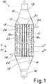
- Figure 1 shows an exchanger as a whole denoted by 10, produced according to principles of the present invention.
- the exchanger 10 comprises a pressurised shell 11, at the opposite ends of which there are conical diffusers or manifolds 12, 13, to which pipes 14, 15 are fitted for the inlet and outlet of the fluid to be cooled (for example, ethylene steam).
- a tube bundle 18 is arranged in the shell between the tubesheets 16 and 17 in order to be immersed in the exchanging fluid (e.g. water) which circulates in the exchanger via inlet and outlet pipes 19 and 20.
- the tubesheets are of the kind known as "thin" and are, therefore, flexible tubesheets, which means that the capacity to withstand flexion due to the internal pressure of the exchanger is ensured by the said tube bundle welded between the tubesheets, and the tubesheets flex outwards also due to the thermal expansion of the bundle.
- the tube bundle advantageously comprises a central zone devoid of tubes and in such area the tubesheets are reciprocally interconnected by tie rods 21.
- the tubes denoted as a whole with 18a and intended to be flowed through by the fluid to be cooled, are arranged around the central zone with the tie rods 21.
- the central zone - devoid of tubes but equipped with tie rods - comprises the centre of the tubesheets.
- the core of the bundle is composed solely of tie rods which do not take part in the circulation of the fluid to be cooled and the tubes are arranged in a torus around the tie rods.
- the area with solely tie rods can be, approximately, in correspondence with the section of the inlet pipe 14.
- the tie rods can be filled with solid metal elements or tubes similar to the tubes in the bundle but sealed at the ends.
- the inertia and section surface area thereof will be comparable to that of the exchanging tubes.
- Figure 2 shows, by way of example, a possible arrangement of the bundle, showing the central tie rods (advantageously arranged in a crosswise fashion) and the tubes surrounding such tie rods.
- the tie rods between the tubesheets help to withstand the pressure thrust between the tubesheets.
- the tie rods can transfer the pressure thrust acting on the said tubesheets from one tubesheet to the other.
- the tie rods are immersed in the cooling fluid just like the tubes but, since such rods are not flowed through by the hot fluid, they have the same temperature as the cooling fluid (for example, in an exchanger for ethylene with exchanging water, such rods can be - for example - approximately 10 °C colder than the exchanging tubes surrounding them).
- the arrangement is therefore advantageous because the buckling of the flexible tubesheets due to the pressure is mitigated in the central part by the different temperature profiles of the tubes and tie rods. Since the stresses are proportional to the deformations, the central part of the flexible tubesheets is less stressed than in the commonly known design solutions.
- the tubes are also less stressed by an axial load, because the further away one moves from the centre, proceeding outwards in a radial fashion, the more the axial stress decreases and the more the flexural stress increases due to the flexion (buckling due to pressure) of the tubesheet.
- the gas distribution in the tubes can be optimised.
- the gas flow is diverted to the tubes surrounding the tie rods and a more uniform distribution of the gas can be obtained in all the exchange tubes, in addition to a minimisation of the formation of vortices and a reduced time of stay in the distribution cone for the flue gas (i.e. better yield from the rapid flue gas cooling reactions).
- the improved distribution of axial forces within the bundle also means that the wall of the most outer peripheral tubes (where the flexural stress component is greater than the axial stress) can be thinner, thereby increasing the internal aperture of the passageway.
- an increased passageway aperture at the periphery of the bundle results in the gas particles - which have to travel freely along a route which is, on average, longer in order to reach the peripheral tubes - having nevertheless the advantage of being exposed to a greater surface area and therefore lower losses of pressure.
- the thicker tubes in the inner part have a greater margin against potential catastrophic ruptures in the event of thinning due to corrosion (even though, with the solution described here, corrosion is either reduced or eliminated).
- an insert 22 can also be featured, arranged in correspondence with the tie rods on the inlet tubesheet 16 on the hot side, in order to reduce the volume in the inlet conical diffuser.
- the insert 22 with a form which is generally tapered in the incoming flow direction, can be easily optimised by means of a computational fluid dynamics system, in order to better match the conformation of the conical diffuser.
- the insert can be made in one piece with the tubesheet or fitted thereonto in various ways, for example by keying.
- a removable fitting can be advantageous in order to be able to replace the insert when, possibly, worn, thereby constituting a sacrificial tubesheet for the protection of the thin tubesheet therebehind.
- diaphragms can also be used in the exchanger according to the invention, arranged transversely along the bundle, to convey the exchanging fluid.
- such diaphragms have the form of discs 23 and rings 24, which alternate along the axis of the bundle in order to ensure circulation as shown by the arrows in Figure 1 , in other words, winding between a peripheral passageway and a central passageway.
- the exchanger in particular a TLE
- the exchanger is, in fact, preferably vertical, with an ascending motion of the fluid (flue gases) to be cooled.
- the first and the last diaphragm have, advantageously, a ring conformation.
- the tie rods are, advantageously, present.
- the central part of the tubesheet is exposed to a speed of approximately zero and therefore there is always a risk, in such central zone, of the accumulation of debris/deposits with consequent overheating locally, since the deposits and fouling in general are an additional thermal resistance which prevents removal of the heat from the tubesheet by the cooling fluid.
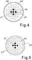
- FIG 4 there is a section of the exchanger shown which shows an advantageous embodiment of one of the ring-shaped diaphragms 24, with the central hole 25 whose perimeter follows the contour of the bundle of tie rods 21 (for example, advantageously arranged in a cross fashion) so that the solid crown part of the baffle is traversed by the exchange tubes and, preferably, supported thereby.
- the baffle may also have a minimum space between the peripheral edge thereof and the inner wall of the exchanger 26.
- the possibility of using ring-shaped diaphragms in proximity to the internal faces of the tubesheets also allows improved inlet and outlet circulation of the cooling fluid.
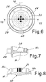
- radial channels 28 can be advantageously featured on the edge of the tubesheet within the exchange chamber.
- the channels 28 are connected to the respective inlet pipes 19 through a connection pipe, for example, in the form of a torus 29 around the periphery of the exchanger.
- such channels are a plurality and are distributed evenly around the circumference of the tubesheet.
- the radial channels 28 face the interior of the exchanger in order to take in the flow of cooling fluid between the tubesheet and the facing ring-shaped baffle.
- the opposite end of the exchange chamber can also feature a similar structure of radial channels 28 for the outlet of exchanging fluid in proximity to the opposite tubesheet 17.
- the solution described above prevents a descending vertical two-phase flow, which would be unstable and/or pulsatile for certain operating points/surface speeds of the liquid and vapour phases.
- the described adduction and extraction arrangement for the exchanging fluid also allows a circular fluid flow symmetry and a configuration known as a 'No Tubes In The Window' configuration, in which all the heat exchange tubes have the same Euler's critical load, regardless of the radial position thereof within the bundle.
- Figure 8 shows a further advantageous embodiment, according to which the tubesheet has a local thickening 30 in the central part, in correspondence with the tie rods 21, which can be used as a corrosion/erosion allowance.
- This thickening is always possible thanks to the fact that, with the structure according to the invention, the central part of the tubesheet is always at approximately the same temperature as the exchanging fluid.
- the thickening can also implement or comprise the external flow diversion insert.
- a tube bundle exchanger with flexible tubesheets produced according to the invention is prone to much fewer erosion and corrosion effects and also allows greater efficiency and flexibility of use. Also, it should be noted that, thanks to the principles of the invention, it is also possible to produce an exchanger which is symmetrical with respect to the transverse plane, i.e., which can be overturned, for example, to extend the working life thereof.
- IBW Internal Bore Welding welds
Landscapes
- Engineering & Computer Science (AREA)
- Physics & Mathematics (AREA)
- Thermal Sciences (AREA)
- Mechanical Engineering (AREA)
- General Engineering & Computer Science (AREA)
- Heat-Exchange Devices With Radiators And Conduit Assemblies (AREA)
- Pressure Welding/Diffusion-Bonding (AREA)
Claims (12)
- Wärmetauscher (10) mit einer unter Druck stehenden Hülle (11) und einem Rohrbündel (18) mit Wärme-tauschenden Rohren (18a) zwischen elastischen Rohrböden (16, 17), worin Die elastischen Rohrböden (16, 17) gegenseitig durch mehrere Zugstäbe (21) in einer zentralen Zone der Rohrböden (16, 17) verbunden sind, dadurch gekennzeichnet, dass die zentrale Zone frei von Austauschrohren (18a) ist, und
worin die Austauschrohre (18a) in dem Rohrbündel (18) um die mehreren Zugstäbe (21) angeordnet sind. - Wärmetauscher nach Anspruch 1, dadurch gekennzeichnet, dass die Austauschrohre (18a) im Umfang des Bündels (18) eine geringere Wanddicke aufweisen als die Wanddicke der anderen Austauschrohre (18a) in dem Bündel.
- Wärmetauscher nach Anspruch 1, dadurch gekennzeichnet, dass die Austauschrohre (18a) im Umfang des Bündels einen größeren Durchmesser haben als der der anderen Austauschrohre (18a) in dem Bündel.
- Wärmetauscher nach Anspruch 1, dadurch gekennzeichnet, dass querverlaufende, in Form zwischen Scheiben (23) und Ringen (24) entlang der Achse des Bündels variierende Scheidewände zum Befördern des Austausch-Fluids entlang des Rohrbündels (18) angeordnet sind.
- Wärmetauscher nach Anspruch 4, dadurch gekennzeichnet, dass die dem Rohrboden nächst-liegende Scheidewand ringförmig ist.
- Wärmetauscher nach Anspruch 4, dadurch gekennzeichnet, dass die ringförmigen Scheidewände (24) einen zentralen Durchgang aufweisen (25), der nur durch Zugstangen durchzogen wird.
- Wärmetauscher nach Anspruch 1, dadurch gekennzeichnet, dass mindestens der Einlass-Rohrboden (16) einen von der der heißen Seite des Rohrbodens in der zentralen Zone vorstehenden, in Verbindung mit den Zugstangen stehenden Einsatz (22) aufweist.
- Wärmetauscher nach Anspruch 1, dadurch gekennzeichnet, dass mindestens der Einlass-Rohrboden (16) in der zentralen Zone eine die Verbindung mit den Zugstangen (21) aufweisende größere Dicke als in dem Umfangs-Teil des Rohrbodens aufweist.
- Wärmetauscher nach Anspruch 1, dadurch gekennzeichnet, dass in Nähe zu mindestens dem Einlass-Rohrboden (16) radial verlaufende Kanäle (28) zum Einlass des Austauschfluids vorhanden sind.
- Wärmetauscher nach Anspruch 1, dadurch gekennzeichnet, dass in Nähe zu mindestens dem Auslass-Rohrboden (17), radial verlaufende Kanäle (28) zum Auslass des Austausch-fluids vorhanden sind.
- Wärmetauscher nach Ansprüchen 9 oder 10, dadurch gekennzeichnet, dass die radial verlaufenden Kanäle (28) umlaufend gleichmäßig beabstandet sind.
- Wärmetauscher nach Ansprüchen 9 oder 10, dadurch gekennzeichnet, dass die radial verlaufenden Kanäle (28) zur Aufnahme und zum Auslass des Austauschfluids von einer ringförmigen Röhre (29) umgeben und damit verbunden sind.
Priority Applications (1)
| Application Number | Priority Date | Filing Date | Title |
|---|---|---|---|
| PL16726424T PL3286512T3 (pl) | 2015-04-24 | 2016-04-21 | Płaszczowo-rurowy wymiennik ciepła o poprawionej konstrukcji |
Applications Claiming Priority (2)
| Application Number | Priority Date | Filing Date | Title |
|---|---|---|---|
| ITUB2015A000270A ITUB20150270A1 (it) | 2015-04-24 | 2015-04-24 | Scambiatore di calore a fascio tubiero con saldature IBW |
| PCT/IB2016/052259 WO2016170487A1 (en) | 2015-04-24 | 2016-04-21 | Tube-bundle heat exchanger with improved structure |
Publications (2)
| Publication Number | Publication Date |
|---|---|
| EP3286512A1 EP3286512A1 (de) | 2018-02-28 |
| EP3286512B1 true EP3286512B1 (de) | 2019-06-05 |
Family
ID=53765393
Family Applications (2)
| Application Number | Title | Priority Date | Filing Date |
|---|---|---|---|
| EP16726424.1A Active EP3286512B1 (de) | 2015-04-24 | 2016-04-21 | Rohrbündelwärmetauscher mit verbesserter struktur |
| EP16726423.3A Active EP3286514B1 (de) | 2015-04-24 | 2016-04-21 | Wärmetauscher |
Family Applications After (1)
| Application Number | Title | Priority Date | Filing Date |
|---|---|---|---|
| EP16726423.3A Active EP3286514B1 (de) | 2015-04-24 | 2016-04-21 | Wärmetauscher |
Country Status (4)
| Country | Link |
|---|---|
| EP (2) | EP3286512B1 (de) |
| IT (1) | ITUB20150270A1 (de) |
| PL (1) | PL3286512T3 (de) |
| WO (1) | WO2016170486A1 (de) |
Families Citing this family (5)
| Publication number | Priority date | Publication date | Assignee | Title |
|---|---|---|---|---|
| PL3376150T3 (pl) | 2017-03-14 | 2020-01-31 | Alfa Laval Olmi S.P.A. | Urządzenie ochronne dla urządzenia w postaci płaszcza i rury |
| CN110500905B (zh) * | 2019-07-16 | 2024-05-14 | 上海蓝滨石化设备有限责任公司 | 一种内压板束及其构成的热交换器 |
| CN111964510A (zh) * | 2020-09-16 | 2020-11-20 | 江苏东方瑞吉能源装备有限公司 | 一种多晶硅冷氢化余热回收再利用装置 |
| CN113787246B (zh) * | 2021-10-15 | 2023-06-16 | 中国电建集团山东电力建设第一工程有限公司 | 一种受热面蛇形管防磨瓦焊接方法及蛇形管换热器 |
| IT202200026172A1 (it) * | 2022-12-21 | 2024-06-21 | Giovanni Manenti | Scambiatore di calore con fluidi in configurazione controcorrente invertita e relativo metodo operativo |
Family Cites Families (4)
| Publication number | Priority date | Publication date | Assignee | Title |
|---|---|---|---|---|
| US4943001A (en) * | 1987-07-07 | 1990-07-24 | Nooter Corporation | Tube-type vessel having crevice-free joints and method for manufacturing the same |
| ITMI20020118A1 (it) * | 2002-01-24 | 2003-07-24 | Olmi Spa | Scambiatore di calore con piastra tubiera sottile con struttura perfezionata |
| CN202675999U (zh) * | 2012-06-19 | 2013-01-16 | 中国石油化工股份有限公司 | 一种换热器结构 |
| CN103528405A (zh) * | 2013-10-17 | 2014-01-22 | 陕西盛迈石油有限公司 | 一种立式管壳式急冷换热器 |
-
2015
- 2015-04-24 IT ITUB2015A000270A patent/ITUB20150270A1/it unknown
-
2016
- 2016-04-21 PL PL16726424T patent/PL3286512T3/pl unknown
- 2016-04-21 EP EP16726424.1A patent/EP3286512B1/de active Active
- 2016-04-21 EP EP16726423.3A patent/EP3286514B1/de active Active
- 2016-04-21 WO PCT/IB2016/052257 patent/WO2016170486A1/en not_active Ceased
Non-Patent Citations (1)
| Title |
|---|
| None * |
Also Published As
| Publication number | Publication date |
|---|---|
| ITUB20150270A1 (it) | 2016-10-24 |
| PL3286512T3 (pl) | 2019-10-31 |
| EP3286514A1 (de) | 2018-02-28 |
| WO2016170486A1 (en) | 2016-10-27 |
| EP3286514B1 (de) | 2019-12-11 |
| EP3286512A1 (de) | 2018-02-28 |
Similar Documents
| Publication | Publication Date | Title |
|---|---|---|
| CA2982899C (en) | Tube-bundle heat exchanger having centrally located tie rods surrounded by exchanger tubes | |
| EP3286512B1 (de) | Rohrbündelwärmetauscher mit verbesserter struktur | |
| US4401153A (en) | Heat exchanger incorporating nitriding-resistant material | |
| US4332294A (en) | Gas cooler with multiply deformed lead tubes | |
| KR102406322B1 (ko) | 열악한 사용 조건을 위한 열교환기 | |
| EP1787081B1 (de) | Rohrbündelvorrichtung mit reduzierter schwingung | |
| EP4390289B1 (de) | Wärmetauscher mit fluiden in umgekehrter gegenstromkonfiguration und betriebsverfahren dafür | |
| EP0390420A1 (de) | Kombiniertes Wärmeaustauschsystem für Reaktionsströme der Ammoniaksynthese | |
| CN110207508A (zh) | 一种换热器 | |
| CN210242495U (zh) | 一种换热器 | |
| CN114894009A (zh) | 一种具有动态随紧密封折流板的换热器 | |
| US11306972B2 (en) | Shell and tube heat exchangers | |
| JP5762237B2 (ja) | 多管式熱交換器 | |
| JP4891353B2 (ja) | 1次流体と2次流体の間の熱交換のための組立体 | |
| CN212884913U (zh) | 高效冷却的结晶器铜管 | |
| CN110567296A (zh) | 高效低阻的滑油冷却器 | |
| CN211204991U (zh) | 一种新型的折流杆换热器装置 | |
| JPS6128584A (ja) | 双塔式ガス化システムの水冷壁 | |
| US3435890A (en) | Heat exchanger | |
| CN209230361U (zh) | 防爆型双管板密封碳化硅列管换热器 | |
| JPS6337880B2 (de) | ||
| CN106500538B (zh) | 一种双流程板管式换热器 | |
| CN216898452U (zh) | 一种自然通风式循环水干式冷却系统 | |
| EP4281724B1 (de) | Rohrwärmetauscher | |
| CN210079505U (zh) | U型管反应釜 |
Legal Events
| Date | Code | Title | Description |
|---|---|---|---|
| STAA | Information on the status of an ep patent application or granted ep patent |
Free format text: STATUS: THE INTERNATIONAL PUBLICATION HAS BEEN MADE |
|
| TPAC | Observations filed by third parties |
Free format text: ORIGINAL CODE: EPIDOSNTIPA |
|
| PUAI | Public reference made under article 153(3) epc to a published international application that has entered the european phase |
Free format text: ORIGINAL CODE: 0009012 |
|
| STAA | Information on the status of an ep patent application or granted ep patent |
Free format text: STATUS: REQUEST FOR EXAMINATION WAS MADE |
|
| 17P | Request for examination filed |
Effective date: 20170921 |
|
| AK | Designated contracting states |
Kind code of ref document: A1 Designated state(s): AL AT BE BG CH CY CZ DE DK EE ES FI FR GB GR HR HU IE IS IT LI LT LU LV MC MK MT NL NO PL PT RO RS SE SI SK SM TR |
|
| AX | Request for extension of the european patent |
Extension state: BA ME |
|
| DAV | Request for validation of the european patent (deleted) | ||
| DAX | Request for extension of the european patent (deleted) | ||
| GRAP | Despatch of communication of intention to grant a patent |
Free format text: ORIGINAL CODE: EPIDOSNIGR1 |
|
| STAA | Information on the status of an ep patent application or granted ep patent |
Free format text: STATUS: GRANT OF PATENT IS INTENDED |
|
| INTG | Intention to grant announced |
Effective date: 20181127 |
|
| GRAS | Grant fee paid |
Free format text: ORIGINAL CODE: EPIDOSNIGR3 |
|
| GRAA | (expected) grant |
Free format text: ORIGINAL CODE: 0009210 |
|
| STAA | Information on the status of an ep patent application or granted ep patent |
Free format text: STATUS: THE PATENT HAS BEEN GRANTED |
|
| AK | Designated contracting states |
Kind code of ref document: B1 Designated state(s): AL AT BE BG CH CY CZ DE DK EE ES FI FR GB GR HR HU IE IS IT LI LT LU LV MC MK MT NL NO PL PT RO RS SE SI SK SM TR |
|
| REG | Reference to a national code |
Ref country code: GB Ref legal event code: FG4D |
|
| REG | Reference to a national code |
Ref country code: CH Ref legal event code: EP |
|
| REG | Reference to a national code |
Ref country code: AT Ref legal event code: REF Ref document number: 1140443 Country of ref document: AT Kind code of ref document: T Effective date: 20190615 |
|
| REG | Reference to a national code |
Ref country code: IE Ref legal event code: FG4D |
|
| REG | Reference to a national code |
Ref country code: DE Ref legal event code: R096 Ref document number: 602016014842 Country of ref document: DE |
|
| REG | Reference to a national code |
Ref country code: NL Ref legal event code: MP Effective date: 20190605 |
|
| REG | Reference to a national code |
Ref country code: LT Ref legal event code: MG4D |
|
| PG25 | Lapsed in a contracting state [announced via postgrant information from national office to epo] |
Ref country code: ES Free format text: LAPSE BECAUSE OF FAILURE TO SUBMIT A TRANSLATION OF THE DESCRIPTION OR TO PAY THE FEE WITHIN THE PRESCRIBED TIME-LIMIT Effective date: 20190605 Ref country code: AL Free format text: LAPSE BECAUSE OF FAILURE TO SUBMIT A TRANSLATION OF THE DESCRIPTION OR TO PAY THE FEE WITHIN THE PRESCRIBED TIME-LIMIT Effective date: 20190605 Ref country code: SE Free format text: LAPSE BECAUSE OF FAILURE TO SUBMIT A TRANSLATION OF THE DESCRIPTION OR TO PAY THE FEE WITHIN THE PRESCRIBED TIME-LIMIT Effective date: 20190605 Ref country code: HR Free format text: LAPSE BECAUSE OF FAILURE TO SUBMIT A TRANSLATION OF THE DESCRIPTION OR TO PAY THE FEE WITHIN THE PRESCRIBED TIME-LIMIT Effective date: 20190605 Ref country code: LT Free format text: LAPSE BECAUSE OF FAILURE TO SUBMIT A TRANSLATION OF THE DESCRIPTION OR TO PAY THE FEE WITHIN THE PRESCRIBED TIME-LIMIT Effective date: 20190605 Ref country code: FI Free format text: LAPSE BECAUSE OF FAILURE TO SUBMIT A TRANSLATION OF THE DESCRIPTION OR TO PAY THE FEE WITHIN THE PRESCRIBED TIME-LIMIT Effective date: 20190605 Ref country code: NO Free format text: LAPSE BECAUSE OF FAILURE TO SUBMIT A TRANSLATION OF THE DESCRIPTION OR TO PAY THE FEE WITHIN THE PRESCRIBED TIME-LIMIT Effective date: 20190905 |
|
| PG25 | Lapsed in a contracting state [announced via postgrant information from national office to epo] |
Ref country code: RS Free format text: LAPSE BECAUSE OF FAILURE TO SUBMIT A TRANSLATION OF THE DESCRIPTION OR TO PAY THE FEE WITHIN THE PRESCRIBED TIME-LIMIT Effective date: 20190605 Ref country code: GR Free format text: LAPSE BECAUSE OF FAILURE TO SUBMIT A TRANSLATION OF THE DESCRIPTION OR TO PAY THE FEE WITHIN THE PRESCRIBED TIME-LIMIT Effective date: 20190906 Ref country code: LV Free format text: LAPSE BECAUSE OF FAILURE TO SUBMIT A TRANSLATION OF THE DESCRIPTION OR TO PAY THE FEE WITHIN THE PRESCRIBED TIME-LIMIT Effective date: 20190605 Ref country code: BG Free format text: LAPSE BECAUSE OF FAILURE TO SUBMIT A TRANSLATION OF THE DESCRIPTION OR TO PAY THE FEE WITHIN THE PRESCRIBED TIME-LIMIT Effective date: 20190905 |
|
| REG | Reference to a national code |
Ref country code: AT Ref legal event code: MK05 Ref document number: 1140443 Country of ref document: AT Kind code of ref document: T Effective date: 20190605 |
|
| PG25 | Lapsed in a contracting state [announced via postgrant information from national office to epo] |
Ref country code: NL Free format text: LAPSE BECAUSE OF FAILURE TO SUBMIT A TRANSLATION OF THE DESCRIPTION OR TO PAY THE FEE WITHIN THE PRESCRIBED TIME-LIMIT Effective date: 20190605 Ref country code: PT Free format text: LAPSE BECAUSE OF FAILURE TO SUBMIT A TRANSLATION OF THE DESCRIPTION OR TO PAY THE FEE WITHIN THE PRESCRIBED TIME-LIMIT Effective date: 20191007 Ref country code: SK Free format text: LAPSE BECAUSE OF FAILURE TO SUBMIT A TRANSLATION OF THE DESCRIPTION OR TO PAY THE FEE WITHIN THE PRESCRIBED TIME-LIMIT Effective date: 20190605 Ref country code: RO Free format text: LAPSE BECAUSE OF FAILURE TO SUBMIT A TRANSLATION OF THE DESCRIPTION OR TO PAY THE FEE WITHIN THE PRESCRIBED TIME-LIMIT Effective date: 20190605 Ref country code: CZ Free format text: LAPSE BECAUSE OF FAILURE TO SUBMIT A TRANSLATION OF THE DESCRIPTION OR TO PAY THE FEE WITHIN THE PRESCRIBED TIME-LIMIT Effective date: 20190605 Ref country code: EE Free format text: LAPSE BECAUSE OF FAILURE TO SUBMIT A TRANSLATION OF THE DESCRIPTION OR TO PAY THE FEE WITHIN THE PRESCRIBED TIME-LIMIT Effective date: 20190605 Ref country code: AT Free format text: LAPSE BECAUSE OF FAILURE TO SUBMIT A TRANSLATION OF THE DESCRIPTION OR TO PAY THE FEE WITHIN THE PRESCRIBED TIME-LIMIT Effective date: 20190605 |
|
| PG25 | Lapsed in a contracting state [announced via postgrant information from national office to epo] |
Ref country code: IS Free format text: LAPSE BECAUSE OF FAILURE TO SUBMIT A TRANSLATION OF THE DESCRIPTION OR TO PAY THE FEE WITHIN THE PRESCRIBED TIME-LIMIT Effective date: 20191005 Ref country code: SM Free format text: LAPSE BECAUSE OF FAILURE TO SUBMIT A TRANSLATION OF THE DESCRIPTION OR TO PAY THE FEE WITHIN THE PRESCRIBED TIME-LIMIT Effective date: 20190605 |
|
| REG | Reference to a national code |
Ref country code: DE Ref legal event code: R097 Ref document number: 602016014842 Country of ref document: DE |
|
| PG25 | Lapsed in a contracting state [announced via postgrant information from national office to epo] |
Ref country code: TR Free format text: LAPSE BECAUSE OF FAILURE TO SUBMIT A TRANSLATION OF THE DESCRIPTION OR TO PAY THE FEE WITHIN THE PRESCRIBED TIME-LIMIT Effective date: 20190605 |
|
| PLBE | No opposition filed within time limit |
Free format text: ORIGINAL CODE: 0009261 |
|
| STAA | Information on the status of an ep patent application or granted ep patent |
Free format text: STATUS: NO OPPOSITION FILED WITHIN TIME LIMIT |
|
| PG25 | Lapsed in a contracting state [announced via postgrant information from national office to epo] |
Ref country code: DK Free format text: LAPSE BECAUSE OF FAILURE TO SUBMIT A TRANSLATION OF THE DESCRIPTION OR TO PAY THE FEE WITHIN THE PRESCRIBED TIME-LIMIT Effective date: 20190605 |
|
| 26N | No opposition filed |
Effective date: 20200306 |
|
| PG25 | Lapsed in a contracting state [announced via postgrant information from national office to epo] |
Ref country code: SI Free format text: LAPSE BECAUSE OF FAILURE TO SUBMIT A TRANSLATION OF THE DESCRIPTION OR TO PAY THE FEE WITHIN THE PRESCRIBED TIME-LIMIT Effective date: 20190605 |
|
| PG25 | Lapsed in a contracting state [announced via postgrant information from national office to epo] |
Ref country code: MC Free format text: LAPSE BECAUSE OF FAILURE TO SUBMIT A TRANSLATION OF THE DESCRIPTION OR TO PAY THE FEE WITHIN THE PRESCRIBED TIME-LIMIT Effective date: 20190605 |
|
| REG | Reference to a national code |
Ref country code: CH Ref legal event code: PL |
|
| PG25 | Lapsed in a contracting state [announced via postgrant information from national office to epo] |
Ref country code: CH Free format text: LAPSE BECAUSE OF NON-PAYMENT OF DUE FEES Effective date: 20200430 Ref country code: LU Free format text: LAPSE BECAUSE OF NON-PAYMENT OF DUE FEES Effective date: 20200421 Ref country code: LI Free format text: LAPSE BECAUSE OF NON-PAYMENT OF DUE FEES Effective date: 20200430 |
|
| REG | Reference to a national code |
Ref country code: BE Ref legal event code: MM Effective date: 20200430 |
|
| PG25 | Lapsed in a contracting state [announced via postgrant information from national office to epo] |
Ref country code: BE Free format text: LAPSE BECAUSE OF NON-PAYMENT OF DUE FEES Effective date: 20200430 |
|
| GBPC | Gb: european patent ceased through non-payment of renewal fee |
Effective date: 20200421 |
|
| PG25 | Lapsed in a contracting state [announced via postgrant information from national office to epo] |
Ref country code: GB Free format text: LAPSE BECAUSE OF NON-PAYMENT OF DUE FEES Effective date: 20200421 Ref country code: IE Free format text: LAPSE BECAUSE OF NON-PAYMENT OF DUE FEES Effective date: 20200421 |
|
| PG25 | Lapsed in a contracting state [announced via postgrant information from national office to epo] |
Ref country code: MT Free format text: LAPSE BECAUSE OF FAILURE TO SUBMIT A TRANSLATION OF THE DESCRIPTION OR TO PAY THE FEE WITHIN THE PRESCRIBED TIME-LIMIT Effective date: 20190605 Ref country code: CY Free format text: LAPSE BECAUSE OF FAILURE TO SUBMIT A TRANSLATION OF THE DESCRIPTION OR TO PAY THE FEE WITHIN THE PRESCRIBED TIME-LIMIT Effective date: 20190605 |
|
| PG25 | Lapsed in a contracting state [announced via postgrant information from national office to epo] |
Ref country code: MK Free format text: LAPSE BECAUSE OF FAILURE TO SUBMIT A TRANSLATION OF THE DESCRIPTION OR TO PAY THE FEE WITHIN THE PRESCRIBED TIME-LIMIT Effective date: 20190605 |
|
| PGFP | Annual fee paid to national office [announced via postgrant information from national office to epo] |
Ref country code: DE Payment date: 20250429 Year of fee payment: 10 Ref country code: PL Payment date: 20250402 Year of fee payment: 10 |
|
| PGFP | Annual fee paid to national office [announced via postgrant information from national office to epo] |
Ref country code: IT Payment date: 20250424 Year of fee payment: 10 |
|
| PGFP | Annual fee paid to national office [announced via postgrant information from national office to epo] |
Ref country code: FR Payment date: 20250425 Year of fee payment: 10 |