EP3286515B1 - Procédés d'échange thermique dynamique - Google Patents
Procédés d'échange thermique dynamique Download PDFInfo
- Publication number
- EP3286515B1 EP3286515B1 EP16756293.3A EP16756293A EP3286515B1 EP 3286515 B1 EP3286515 B1 EP 3286515B1 EP 16756293 A EP16756293 A EP 16756293A EP 3286515 B1 EP3286515 B1 EP 3286515B1
- Authority
- EP
- European Patent Office
- Prior art keywords
- stream
- heat exchanger
- change
- streams
- conditions
- Prior art date
- Legal status (The legal status is an assumption and is not a legal conclusion. Google has not performed a legal analysis and makes no representation as to the accuracy of the status listed.)
- Active
Links
Images





Classifications
-
- F—MECHANICAL ENGINEERING; LIGHTING; HEATING; WEAPONS; BLASTING
- F28—HEAT EXCHANGE IN GENERAL
- F28F—DETAILS OF HEAT-EXCHANGE AND HEAT-TRANSFER APPARATUS, OF GENERAL APPLICATION
- F28F27/00—Control arrangements or safety devices specially adapted for heat-exchange or heat-transfer apparatus
- F28F27/02—Control arrangements or safety devices specially adapted for heat-exchange or heat-transfer apparatus for controlling the distribution of heat-exchange media between different channels
-
- F—MECHANICAL ENGINEERING; LIGHTING; HEATING; WEAPONS; BLASTING
- F28—HEAT EXCHANGE IN GENERAL
- F28D—HEAT-EXCHANGE APPARATUS, NOT PROVIDED FOR IN ANOTHER SUBCLASS, IN WHICH THE HEAT-EXCHANGE MEDIA DO NOT COME INTO DIRECT CONTACT
- F28D21/00—Heat-exchange apparatus not covered by any of the groups F28D1/00 - F28D20/00
- F28D2021/0019—Other heat exchangers for particular applications; Heat exchange systems not otherwise provided for
-
- Y—GENERAL TAGGING OF NEW TECHNOLOGICAL DEVELOPMENTS; GENERAL TAGGING OF CROSS-SECTIONAL TECHNOLOGIES SPANNING OVER SEVERAL SECTIONS OF THE IPC; TECHNICAL SUBJECTS COVERED BY FORMER USPC CROSS-REFERENCE ART COLLECTIONS [XRACs] AND DIGESTS
- Y02—TECHNOLOGIES OR APPLICATIONS FOR MITIGATION OR ADAPTATION AGAINST CLIMATE CHANGE
- Y02E—REDUCTION OF GREENHOUSE GAS [GHG] EMISSIONS, RELATED TO ENERGY GENERATION, TRANSMISSION OR DISTRIBUTION
- Y02E60/00—Enabling technologies; Technologies with a potential or indirect contribution to GHG emissions mitigation
- Y02E60/14—Thermal energy storage
Definitions
- the present disclosure relates generally to industrial processes. More specifically, the present disclosure relates to methods of dynamically exchanging heat between two or more streams, and systems and devices related thereto.
- This document describes methods, devices, and systems that can decrease or eliminate heat exchanger performance and efficiency losses during transient changes in flow rates or other properties of the streams passing through them. For example, when the flow rate of any one stream entering an optimized and balanced heat exchanger changes, it degrades the heat exchanger performance, creating larger temperature differences in the entering and exiting streams than would otherwise exist. This performance degradation leads to both direct and indirect consequences.
- the direct consequence involves energy consumption and stream exit temperatures outside of their design ranges. These direct results frequently create indirect consequences, such as missing quality control and assurance standards, creating safety or environmental hazards, and disposing or flaring of compromised material. These indirect consequences often raise more concern than the direct consequences.
- Heat exchangers can also limit the rates at which process loads can change.
- the heat exchanger constraints often represent the most restrictive constraints in the process and thereby compromise the agility and responsiveness of processes.
- the imposed constraints often are associated with thermal stresses, expansion, or temperature changes in the devices or their near neighbors in the flow process.
- the methods, systems, and devices described in this document can reduce or eliminate the constraints heat exchangers place on the rate at which loads or other stream properties can change.
- phrases “connected to” and “coupled with” refer to any form of interaction between two or more entities, including mechanical, electrical, magnetic, electromagnetic, fluid, and thermal interaction. Two entities may interact with each other even though they are not in direct contact with each other. For example, two entities may interact with each other through an intermediate entity.
- Methods of dynamically exchanging heat between two or more streams may comprise methods of managing heat transfer between streams and/or methods of rapidly changing upstream conditions while reducing downstream temperature deviations.
- the methods comprise exchanging heat between a first stream and a second stream, wherein the first stream comprises an upstream portion and a downstream portion and wherein the second stream also comprises an upstream portion and a downstream portion.
- the invention is defined by the features of claim 1.
- heat transfer between the streams may be managed to reduce deviations from a design temperature of the downstream portion of the stream. For instance, deviations from the design temperature may be reduced to a percent deviation of about 25% or less, about 20% or less, about 15% or less, about 10% or less, about 5% or less, or about 1 % or less. Percent deviation may be calculated as actual deviation, divided by potential deviation without adding or removing material, times 100.
- the methods disclosed herein may further comprise identifying the existence of a change in conditions in either the first stream or the second stream, such as at a heat exchanger outlet of the stream experiencing the change. Likewise, the identification may occur prior to any deviation in the design temperature of the downstream portion of the stream experiencing the change, such as prior to the upstream portion of the stream experiencing the change entering the heat exchanger (i.e., at the inlet or further upstream).
- Some embodiments may comprise determining whether the change in conditions is a permanent change or a temporary change. For example, for a temporary change in conditions, an optimal amount of material to be added or removed from the upstream portion of the stream not experiencing the change in conditions may be determined so as to optimize the heat transfer. For example, a profile over time or location, or both, for the temporary change in conditions may be determined. Likewise, a corresponding profile over time or location, or both, for the addition or removal of material that will maintain the desired design temperature may be determined as well.
- a profile may be determined over time of an amount of material to be added or removed from the upstream portion of the second stream that will maintain a design temperature of the downstream portion of the first stream. For example, material from a reservoir may be initially added, or material may be initially removed to the reservoir. The reservoir will generally be separate from a primary source of the second stream. The conditions of the primary source of the second stream are then gradually adjusted until material does not need to be added from the reservoir or removed to the reservoir to maintain the design temperature of the downstream portion of at least the first stream.
- Methods disclosed herein may further comprise appropriately timing the addition or removal of material. This may avoid a deviation in the design temperature of the downstream portion of the stream experiencing the change, or in any stream not experiencing the change.
- the percent deviation from the design temperature may be reduced by about 25% or less, about 20% or less, about 15% or less, about 10% or less, about 5% or less, or about 1% or less.
- Timing the addition or removal of material may utilize feed-forward control, model-predictive control, or similar control strategies. As discussed, timing the addition of material to or removal of material from the upstream portion of the stream not experiencing a change in conditions may substantially maintain balance in a heat exchanger.
- managing heat transfer between streams may occur in a certain time range. For example, managing heat transfer between the first stream and the second stream may occur within about 30 seconds or less, about 15 seconds or less, about 5 seconds or less, about 2 seconds or less, or about 1 second or less of the change in conditions of one of the streams.
- exchanging heat between two streams may occur with one or more additional streams while exchanging heat between the first stream and the second stream.
- the first stream and the second stream may flow counter-current, parallel, or perpendicular to each other.
- the methods may further comprise adding the same material already present in the stream or adding different material from that present in the stream.
- the methods comprise exchanging heat between two or more streams under steady-state conditions.
- the methods may further comprise adding material to an independent stream in thermal communication with the two or more streams, when any or all of the two or more streams experience a change in conditions, to thereby manage heat transfer between the two or more streams during the change in conditions.
- the upstream portions of some or all of the two or more streams may be at different temperatures.
- the independent stream may comprise a discontinuous stream with a higher-temperature storage tank at one end of the stream and a lower-temperature storage tank at the other end of the stream.
- the higher-temperature storage tank may be maintained at a higher level and the lower-temperature storage tank at a lower level. This may be implemented when the two or more streams comprise a cooler temperature stream at risk for flow rate increases and/or the two or more streams comprise a higher temperature stream at risk for flow rate decreases.
- Higher-temperature material may be readily added to the independent stream to thereby manage heat transfer between the two or more streams and maintain a design temperature of a downstream portion of at least one stream experiencing a change.
- the higher-temperature storage tank may be maintained at a lower level and the lower-temperature storage tank at a higher level when the two or more streams comprise a cooler temperature stream at risk for flow rate decreases and/or the two or more streams comprise a higher temperature stream at risk for flow rate increases. This may allow that lower-temperature material to be readily added to the independent stream to thereby manage heat transfer between the two or more streams and maintain a design temperature of a downstream portion of at least one stream experiencing a change.
- the higher-temperature storage tank may be maintained at a moderate level and the lower-temperature storage tank at a moderate level. This may allow the lower-temperature material or higher-temperature material to be readily added to the independent stream to thereby manage heat transfer between the two or more streams and maintain a design temperature of a downstream portion of at least one stream experiencing a change.
- Material may be shuttled between the higher-temperature storage tank and the lower-temperature storage tank by temporarily adding material to the independent stream when the two or more streams are at steady-state conditions, wherein the adding is conducted at a low enough flow rate that a heat exchanger transferring heat between the two or more streams is substantially balanced during the shuttling of the material.
- the systems comprise a heat exchanger configured to exchange heat between at least a first stream and a second stream, such as, for example, a double-pipe heat exchanger, shell-and-tube heat exchanger, plate heat exchanger, or plate-and-shell heat exchanger.
- the systems may further comprise a first flow diverter located in an upstream portion of the first stream.
- the first flow diverter may be in fluid communication with a primary source of the first stream and also in fluid communication with a first reservoir.
- the first flow diverter may be configured to optionally divert material from the upstream portion of the first stream to the first reservoir or optionally add material from the first reservoir to the upstream portion of the first stream.
- the system may further comprise a control system configured to control the first flow diverter to thereby control adding material to or removing material from the upstream portion of the first stream, when the upstream portion of at least the second stream is experiencing a change in conditions, thereby changing heat transfer between at least the first stream and the second stream.
- a control system configured to control the first flow diverter to thereby control adding material to or removing material from the upstream portion of the first stream, when the upstream portion of at least the second stream is experiencing a change in conditions, thereby changing heat transfer between at least the first stream and the second stream.
- the methods comprise supplying at least a first stream and at least a second stream to a heat exchanger system of the above paragraph.
- the methods may further comprise rapidly changing the condition of the upstream portion of the second stream from an initial condition to a new condition and comparatively slowly changing the condition of the primary source of the first stream from an initial condition to a new condition, wherein the heat exchanger is substantially balanced when the first and second streams are each in the initial conditions, and the heat exchanger is substantially balanced when the first and second streams are each in the new conditions.
- the methods may further comprise temporarily adding material from the reservoir to the upstream portion of the first stream or temporarily removing material from the upstream portion of the first stream to the reservoir, to substantially maintain heat transfer balance in the heat exchanger while the primary source of the first stream is changing to its new condition.
- the systems comprise a heat exchanger configured to exchange heat between two or more streams and an independent stream.
- the systems may further comprise a reservoir in fluidic communication with the independent stream.
- the systems may further comprise a control system configured to control adding material to the independent stream from the reservoir, when an upstream portion of any or all of the two or more streams experiences a change in conditions, to thereby change heat transfer between the two or more streams.
- the methods comprise supplying two or more streams to a heat exchanger system of the above paragraph.
- the methods may further comprise rapidly changing the condition of the upstream portion of at least one of the two or more streams from an initial condition to a new condition, and comparatively slowly changing the condition of the upstream portion of a different one of the two or more streams from an initial condition to a new condition, wherein the heat exchanger is substantially balanced when the two or more streams are each in their respective initial condition, and the heat exchanger is also balanced when the two or more streams are each in their respective new condition.
- the methods may further comprise temporarily adding material from the reservoir to the independent stream to substantially maintain heat transfer balance in the heat exchanger while the different stream is changing to its new condition.
- Figure 1 illustrates a generic, counter-current, two-stream heat exchanger that could be plate-and-frame, brazed-plate, shell-and-tube, or essentially any other design.
- Hot and cold streams flow into the exchanger on the left and right sides, respectively, and exchange heat such that the hot stream cools and the cold stream warms.
- the terminology for the outlet streams used here is common in the industry, but it is both possible and common that the hot stream outlet temperature is colder than the cold stream outlet temperature, leading to possible confusion if one considers temperatures after heat exchange.
- Heat exchanger efficiency may be defined as the initial Gibbs energy in the incoming streams that is converted to entropy during heat exchange, normalized by the largest possible entropy formation with the incoming streams.
- Figure 2 illustrates the internal temperature profiles in a balanced, counter-current heat exchanger.
- the hot and cold stream temperature profiles parallel each other, with the temperature profile of the thin metal plate separating them lying at the average of the stream temperatures in this case.
- Figure 3 illustrates the temperature profiles for a similar heat exchanger in which heat transfer coefficients between the cold stream and the separation plate are higher than those involving the hot stream, resulting in a larger temperature difference between the hot stream and the separation plate and a correspondingly smaller difference between the cold stream temperature and the separation plate.
- Such differences and their converses are common, but such a heat exchanger is still balanced.
- a balanced heat exchanger maximizes the efficiency within the constraints of the heat exchanger design and the flow rates.
- the inlet of the hot stream lies at the same position or value of x as the outlet of the cold stream, and vice versa.
- Simple heat exchangers in this context, have (a) streams with constant heat capacities, densities, and velocities, (b) no phase changes, reactions, or other complex behavior in the exchanger, and (c) heat transfer rates that are approximately equal in all parts of the exchanger. Complex exchangers can exhibit maximum efficiency under conditions where the temperature differences are not necessarily equal ( Figure 4 ).
- the mass flow rate in this ratio is a signed value, with flow rates in opposite directions having opposite signs.
- the index i is 1 for the hot flow and 2 for the cold flow. If the heat exchanger involves more than one hot or cold flow, ⁇ becomes the sum of these products for all of the flows in the direction of the hot streams divided by the sum for all of the flows in the cold stream. If the streams do not have the same cross-sectional areas perpendicular to the flow, the definition includes these areas ( A i ).
- ⁇ x ⁇ hot A i v i ⁇ i c p , i ⁇ cold A i v i ⁇ i c p , i
- ⁇ In a simple, balanced heat exchanger, ⁇ usually is at or near a value of -1. In real fluids with heat capacities, densities, geometries, and other properties that vary with temperature and position, ⁇ depends on position. In such cases, an average value of ⁇ close to -1 should be near the balanced heat exchanger condition if there are no phase changes or other complexities. Heat transfer coefficients in the heat exchanger also vary with position.
- both sides of the heat exchanger have the same heat transfer coefficient.
- the hot and cold stream temperatures differ by the same amount, about 10 °C in this case, at all locations in the heat exchanger.
- the heat transfer coefficient for the hot stream is 25% lower and that of the cold stream is 25% higher than the conditions in Figure 2 .
- the hot stream flow rate increases by 35%, the value of ⁇ changes from - 1 to -1.35 and the resulting heat exchanger temperature profiles approximate those shown in Figure 5 .
- the same effect could be caused by increasing the hot-side heat capacity, channel thickness, or density or, equivalently, decreasing one of the same properties of the cold stream by 35%, relative to the values that produced the results in Figure 2 .
- the difference in the hot and cold stream temperatures decreases on the end near the hot inlet to the heat exchanger by about 8 °C, from about 10 °C to about 2 °C, and increases on the end with the cold inlet to the exchanger by about 10 °C, from about 10 °C to about 20 °C.
- the increase on the cold end is much larger than the decrease on the hot end.
- Figure 4 illustrates heat exchanger temperature profiles for a system in which there is a phase change.
- the methods, systems, and devices disclosed herein provide means to reduce or minimize these transient effects and apply broadly to heat exchangers and fluids of nearly all types.
- the dynamic heat exchanger system can either retrofit an existing heat exchanger or use an entirely new heat exchanger.
- the following discussion first discusses the retrofit option in the context of a conventional, two-stream exchanger and applies most conveniently to a system that involves relatively high volumetric heat capacities, such as two liquid streams.
- a new heat exchanger with one or more additional streams may be better if one or more of the streams have low volumetric heat capacities, such as gases, or if there is some safety, environmental, or similar reason not to install t-joints in existing lines.
- the discussion of this non-retrofit version follows that of the retrofit option in the context of adding one additional stream to a two-stream version.
- the retrofit system requires one or more additional valves, pumps, and tanks but does not require replacing or moving an existing heat exchanger.
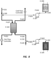
- a simplified form modifies an existing heat exchanger (E-102), hot and cold inlet flows (P-533/637 and P-639/636, respectively), outlet flows (P-643 and P-651), and flow controllers.
- the modifications include a valve, bidirectional pump, and tank with optional heating or cooling or insulation for each of the hot and cold inlet lines (V-209, E-107, E-105 and E-106, respectively for the hot flow, and V-210, E-108, E-104, and E-103, respectively, for the cold flow) connected with bidirectional pipes (P-654 and P-644 for the hot flow, and P-653 and P-642 for the cold flow).
- the pumps would normally have associated controllers (not illustrated), which would need to be bidirectional or able to control flows in both directions. It should be understood that this system needs only the equipment connected to the hot or the cold flow, not both, though both appear in this illustration.
- the dynamic system creates a compensating flow using the ancillary systems such that the flow through the heat exchanger remains balanced, the level of material in the tanks changes, and the heat exchanger operates at its highest efficiency.
- the upset passes or the transient subsides, flows in the ancillary systems return to zero.
- the system levels oscillating changes in demand, random transients, and other dynamics.
- a future transient or upset in the opposite direction may allow the system to return to its original condition, including the original levels of stored material in the tank.
- the tanks may also be refilled from other sources or filled relatively slowly from the process streams.
- bidirectional pumps are rare and both inefficient and expensive compared to traditional unidirectional counterparts.
- Bidirectional controllers are even more rare and expensive.
- the pumps and controllers are expensive compared to valves.
- the remainder of this discussion presumes a configuration that allows a single unidirectional pump to accomplish the same thing, removing the complexity of two pumps and controllers but adding more valves.
- the plumbing complicates the flow diagram, but the operating principle is the same as indicated in the less complex system illustrated in Figure 8 .
- the dynamic, two-stream heat exchanger ( Figure 9 ) includes a conventional heat exchanger (E-76), such as an existing heat exchanger that has been retrofitted with incoming and outgoing hot and cold streams (P-533, P-545, P-594, and P-585, respectively). Sensors include flowmeters on the two outgoing streams (P-594 and P-585) and temperature indicators on the heat exchanger inlets and outlets (TI-1, TI-2, TI-3, and TI-4). All of these components would be typical in a conventional heat exchanger. In balanced operation, no material flows through stream P-542 or P-570 or any of the subsequent plumbing. The heat exchanger operates as usual and the dynamic component remains idle.
- E-76 conventional heat exchanger
- Sensors include flowmeters on the two outgoing streams (P-594 and P-585) and temperature indicators on the heat exchanger inlets and outlets (TI-1, TI-2, TI-3, and TI-4). All of these components would be typical in a conventional heat exchanger. In balanced operation, no material flows
- the dynamic operation activates during imbalanced operation and uses the t-junctions in the incoming and outgoing streams and the equipment to which they connect, as indicated in the diagram. All of these modifications can be done as retrofits to an existing heat exchanger, with the only changes to the existing process and plumbing being installation of flow diverters (t-joints, three-way valves, or functional equivalent devices) in the incoming streams of the heat exchanger.
- flow diverters t-joints, three-way valves, or functional equivalent devices
- the incoming hot stream (P-533) (primary source of a first stream) connects to a T-junction (first flow diverter or at least a portion of it), one line from which (P-590) connects to the heat exchanger (E-76) and represents the heat exchanger inlet hot flow.
- the stream connected to the heat exchanger (P-590) may have different properties, commonly a different flow rate, than the incoming hot stream (P-533).
- the second line (P-542) from the T-junction in the incoming hot stream connects to a three-way valve (V-177).
- One line (P-605) from this valve (V-177) connects to the cold side of this process through a three-way valve (V-196), and is discussed later in conjunction with the remaining cold-side components.
- the other line (P-602) from this valve (V-177) connects to a t-joint (joint connecting P-602, P-606, and P-568).
- One line (P-568) from this t-joint leads to the pump (E-79) (transport device) inlet.
- the second line (P-606) from this t-joint connects with a three-way valve (V-189).
- One line (P-603) from this valve connects to a different three-way valve (V-197) which lies on the cold side of the system and is discussed later.
- the second line (P-583) connects to a hot storage tank (E-86) (first reservoir).
- the inlet cold stream (P-545) (a primary source of the second stream) connects to a T-junction (second flow diverter or at least a portion of it), one line from which (P-551) connects to the heat exchanger (E-76) and represents the heat exchanger inlet cold flow. This flow may intentionally differ, such as, for example, in flow rate, from the incoming cold stream (P-545).
- the other line (P-570) from the T-junction connects to a three-way valve (V-196).
- One line (P-605) from this three-way valve (V-196) has already been discussed above.
- the second line (P-607) from the three-way valve (V-196) connects to another T-junction.
- One line (P-550) from this t-joint is the pump (E-79) outlet.
- the other line (P-604) from this T-junction connects to a three-way valve (V-197).
- One line from this three-way valve (V-197) connects to the cold storage (E-81) (second reservoir).
- the other line (P-603) from this three-way valve (V-197) was previously discussed.
- a flow controller/meter for the pump controls the outlet stream (P-550) but could also be on the inlet stream (P-568). Temperature indicators (TI-1, TI-2, TI-3, and TI-4) for the heat exchanger's incoming and outgoing hot and cold streams (P-590, P-551, P-594, and P-585, respectively) could similarly be located in a variety of locations, though locating them close to the heat exchanger (E-76) may be preferable. Flows illustrated with no directional arrows could be in either direction and flow in different directions, depending on operational modes.
- a small portion of the hot and cold streams can mix during dynamic heat exchanger operation.
- the amount of material in the pump inlet and outlet, P-568 and P-550, respectively, and in the pump E-79 and some of the surrounding lines could mix when operation changes modes. This could be prevented, such as, for example, by either using a single stream to do the balancing (e.g., the second flow diverter and the second reservoir are not present) or using separate pumps and dedicated plumbing lines for each reservoir.
- the three-way valves illustrated here could be replaced with more common in-line valves located in pipes P-602, P-603, P-604, and P-605 and accomplish the same control. However, this would slightly increase the potential mixing of materials from the cold and hot streams when operating modes change.
- a heater (E-86) and a chiller (E-81) for the hot and cold storage tanks (E-80 and E-77, respectively) optionally provide means to overcome heat losses and slight temperature differences if needed.
- the tanks also would optionally be insulated.
- Each additional stream could optionally also have a separate reservoir and flow diverter.
- those two or more streams could utilize the same reservoir, but with separate flow diverters.
- a control system (not shown) is configured to control the first flow diverter (incoming hot stream T-junction and associated valves as needed) to thereby control adding material to or removing material from the upstream portion of the first stream (incoming stream of the hot stream), when the upstream portion of at least the second stream (incoming stream of the cold stream) is experiencing a change in conditions, thereby changing heat transfer between at least the first stream and the second stream.
- the control system is further configured to control the second flow diverter (incoming cold stream T-junction and associated valves as needed) to thereby control adding material to or removing material from the upstream portion of the second stream, when the upstream portion of at least the first stream is experiencing a change in conditions, thereby changing heat transfer between at least the first stream and the second stream.
- the heat exchanger is brought closer to its balanced operation by filling or emptying the storage tanks during an operational transient (a change in conditions).
- operational transients include, but are not limited to, a change in flow rate, temperature, pressure, composition, density, heat capacity, or combinations thereof.
- the emptying or filling of the storage tanks changes the relative flow rates in the heat exchanger, which changes the heat transfer between the two streams and can mitigate the effect of the transient.
- the choice of filling or emptying the tank is dictated by the current level of fluids in the tanks.
- the system can also manage transients by both filling one tank and emptying the other (e.g., removing material from the upper portion of the first stream and adding material to the upper portion of the second stream). Exemplary specific operations in specific scenarios are described below but are not intended to limit the possible operation of the existing stream dynamic heat exchanger system.
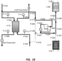
- the first scenario considers a transient where the hot incoming stream (P-533) transports more heat or enthalpy than the cold incoming stream (P-545) can balance in the heat exchanger (
- a portion of the hot stream flows to the hot storage tank (E-80) or a portion of the stored cold material in the cold storage tank (E-77) flows to the cold stream, or some combination thereof, until the transient subsides.
- These scenarios appear in ( Figure 10 and Figure 11 ), with bolded lines representing lines with flow, arrows representing the flow direction, and dashed lines representing lines with no flow.
- Figure 10 illustrates exemplary dynamic heat exchanger system operation when the hot flow stream carries more heat or enthalpy than the cold stream can balance ( ⁇ ⁇ -1) and a portion of the hot flow is stored in the hot storage. Solid lines contain flow moving in the direction indicated by the arrows, and dashed lines have no flow.
- Figure 11 illustrates exemplary dynamic heat exchanger system operation when the hot flow stream carries more heat or enthalpy than the cold stream can balance ( ⁇ ⁇ -1) and the fluid in the cold storage tank supplements the cold flow to help balance the heat exchanger.
- Bold, solid lines contain flow moving in the direction indicated by the arrows, and dashed lines have no flow.
- Figure 12 illustrates exemplary dynamic heat exchanger system operation when the cold flow stream carries less heat or enthalpy than the hot stream can balance (-1 ⁇ ⁇ ⁇ 0) and a portion of the cold flow is stored in the cold storage. Solid lines contain flow moving in the direction indicated by the arrows, and dashed lines have no flow.
- Figure 13 illustrates dynamic heat exchanger system operation when the cold flow stream carries more heat or enthalpy than the hot stream can balance (-1 ⁇ ⁇ ⁇ 0) and the stored hot fluid is used to supplement the hot flow rate. Solid lines contain flow moving in the direction indicated by the arrows, and dashed lines have no flow.
- the temperature at which fluid is stored in the tank may be somewhat closer to the average temperature (cooler in the hot tank and warmer in the cold tank) than the incoming streams. If so, if the heat exchanger is balanced by withdrawing flows, this difference will be smaller than if it is balanced by adding flow.
- the heating/cooling elements and well-insulated tanks can eliminate this difference.
- either of the two storage tanks and the associated plumbing could be eliminated, resulting in managing the transient by either adding or removing just one of the streams.
- the volume of the tanks should be approximately the same as the excess volume of fluid flowing in one of the streams during the transient. For fluid streams with short transients, this represents a manageable volume. For a gas heat stream or a long transient, the volume could be quite large.
- phase change could be accomplished in a single storage vessel or via a separate heat exchanger (i.e., separate from the dynamic heat exchanger).
- the storage vessel could include a phase change material that condenses the gas.
- the phase change material could be a solid form of the gas material (e.g., ice when the gas is steam).
- the gas and the phase change material both become liquids.
- the phase change material could also be a different material from the gas.
- separation and compatibility of the phase change material is not an issue.
- the condensed gas can then be vaporized as needed for supply to the dynamic heat exchanger.
- FIG 14 illustrates another embodiment of a heat exchanger system that utilizes an independent stream, referred to herein as the "non-retrofit system.”
- the non-retrofit system uses similar principles as the retrofit system.
- the non-retrofit system includes as many hot and cold inlets as needed for the process, represented in the figure as a single stream for all hot inlets (P-622) and a different stream for all cold inlets (P-623). These connect to corresponding outlets (P-625 and P-629, respectively).
- At least one independent stream is added on both sides of the heat exchanger (P-624 and P-630), and these streams are materially connected (use the same fluid) through the heat exchanger (E-98) (e.g., may connect to the same tube in the heat exchanger).
- the independent stream(s) (P-624 and P-630) and corresponding pumps and valves represent one or more balancing streams.
- a bidirectional pump, or a unidirectional pump with appropriate valves and plumbing moves fluid in the balancing stream.
- Flowmeters and temperature indicators provide control. At least one flowmeter on the independent stream may suffice for control.
- a control system (not shown) is configured to control adding material to the independent stream from either the hot storage tank or the cold storage tank, when an upstream portion of any or all of the hot or cold streams experiences a change in conditions (i.e., transient), to thereby change heat transfer between the hot and cold streams.
- the non-retrofit dynamic heat exchanger system illustrated in Figure 14 operates much like the retrofit dynamic heat exchanger system illustrated in Figures 8-13 , except that material flows from either the hot storage to the cold storage or vice versa. Illustrations of operation for the cases of too much high enthalpy and too much cold enthalpy appear in Figure 15 and Figure 16 , respectively. Reference to the parameter ⁇ in these figure captions implies a summation in the numerator of all hot streams and in the denominator of all cold streams.
- a benefit of this and the retrofit heat exchanger systems is the ability to minimize the entropy production and the Gibbs energy loss in the heat exchanger. As with the retrofit system, in simple heat exchangers, this occurs as ⁇ approaches - 1. In complex systems involving large variations in heat capacity, condensation, vaporization, reactions, streams entering one side of the heat exchanger at significantly different temperatures, or other complicating factors, entropy and Gibbs energy loss might be minimized when ⁇ differs somewhat from -1. In the case of too much hot ⁇ c p flow, the dynamic heat exchanger compensates by adjusting the balancing stream as shown in Figure 15 . In the converse case, when cold flow exceeds hot flow, dynamic heat exchanger compensation appears in Figure 16 . Unlike the retrofit version, this non-retrofit version generally requires the existing heat exchanger to be replaced by a new exchanger with at least one additional stream.
- An advantage of the non-retrofit system is that a fluid with a high volumetric energy flow can be used to balance a heat exchanger, which in turn will decrease the size of tanks needed for a given magnitude and duration of a transient and may improve the heat transfer rates in the exchanger.
- the new stream may include a fluid near its critical point, a molten metal, a salt solution, or any number of other fluids that have very high volumetric heat capacities.
- the configuration is also slightly less complex.
- Figure 15 illustrates operation of the non-retrofit heat exchanger system when the high-temperature stream contains more energy or enthalpy than can be balanced by the low-temperature stream ( ⁇ ⁇ -1). Solid lines contain flow moving in the direction indicated by the arrows, and dashed lines have no flow.
- Figure 16 illustrates operation of the non-retrofit heat exchanger system when the low-temperature stream contains more energy or enthalpy than can be balanced by the high-temperature stream (-1 ⁇ ⁇ ⁇ 0). Solid lines contain flow moving in the direction indicated by the arrows, and dashed lines have no flow.
- both the retrofit and non-retrofit systems in addition to maintaining optimal efficiency and meeting set points during transients, also allow processes to move through these transients much more rapidly.
- the heat exchangers disclosed herein may maintain essentially the same temperature profile through the transient, the heat exchanger presents little if any barrier to the speed of the transient. Unlike traditional heat exchangers, which experience thermal stresses and other temperature-profile-related performance issues during transients, these heat exchangers may have no such variations. This can allow the process to move through transients, change loads, and follow set points at much more rapid speeds than is otherwise the case.
- the rapid transients are taken to an extreme, with heat exchanger performance monitored during step changes in stream properties.
- the response times are very slow and the temperature gradients can be very high, while the dynamic heat exchangers disclosed herein reduce the response time and the gradients to near zero.
- the retrofit system used a small, commercial (Dudadiesel), two-stream brazed-plate heat exchanger with conventional incoming and outgoing hot and cold streams configured essentially identical to the system shown in Figure 9 .
- Table 1 summarizes geometrical features of this plate heat exchanger.
- Flowmeters Great Plains Industry's TM050-N 1 ⁇ 2" NPT
- Digital control valves Vallworx 5610A-DPS
- Type K thermocouples recorded temperatures of the streams flowing into and out of the heat exchanger.
- a National Instruments board (NI cDAQ-9188XT) connected to a laptop computer provided data acquisition and control.
- Table 1 Main dimension of Dudadiesel B3-12A 10 plate heat exchanger Dimension Value Plate length (in/mm) 7.5/191 Plate width (in) 2.9/74 Plate thickness (in) 0.0118/0.3 Heat transfer area (ft 2 /m 2 ) 1.4/0.13 Height (in) 1.155/29.337
- the non-retrofit system used a custom-built, plate-and-frame, three-stream heat exchanger essentially identical to the illustration in Figure 14 . It used 30 custom-made aluminum plates with incoming and outgoing hot and cold streams and a third stream connecting two storage tanks. The stream pattern between the plates in the heat exchanger cycled through the three streams in sequence.
- Table 2 provides geometrical features of this exchanger.
- Table 2 Geometry of the custom-made three-stream plate heat exchanger Dimension Value Plate length (in/mm) 12/305 Plate width (in/mm) 5/127 Plate thickness (in/mm) 0.031/0.79 Heat transfer area (ft 2 /m 2 ) 40/3.72 Height (in/mm) 4.5/114
- Process streams referred to calculations based on flow rates that approached the heat exchanger prior to the location of their interface with the dynamic heat exchange system.
- Heat exchanger streams referred to calculations based on the flows in the heat exchanger itself.
- the approaching streams included the hot and cold streams. While these labels seem obvious, it was possible that the outlet temperature of the hot stream would be less than the outlet temperature of the cold stream; that is, at the outlet conditions, the hot stream may be colder than the cold stream in some experiments.
- the terms hot and cold refer to the flow properties prior to the heat exchanger and should not be confused with the properties after the heat exchanger.
- Figure 17 illustrates typical temporal variation in the flow rates of the test two-stream, counter-current heat exchanger involving a perturbation from ⁇ ⁇ 1 to ⁇ ⁇ 2.3 (more hot flow than cold flow).
- the active and idle conditions represent results from two separate experiments and show minor differences in conditions.
- the hot and cold flow rate differences, both during the perturbation and before and after it, were nearly identical, providing a good basis for comparison in the efficiencies.
- Figure 18 illustrates typical temporal variation in the outlet temperatures (left ordinate) and ⁇ (right ordinate) in the test two-stream, counter-current heat exchanger with an idle dynamic heat exchanger system.
- the three-stream heat exchanger exhibited conceptually similar features with some differences.
- the flow rates, Figure 19 changed in similar ways, as did the ratio ⁇ , Figure 20 .
- the outlet temperatures responded more slowly than they did in the two-stream version, principally because the stagnant third stream increases the product of the mass and heat capacity and hence increases the response time constant.
- Figure 19 illustrates typical temporal variation in the flow rates of the test three-stream, counter-current heat exchanger in these experiments in which the third stream was stagnant and the dynamic heat exchanger technology was not operating.
- Figure 20 illustrates typical temporal variation in the outlet temperatures (right ordinate) and flow ratio, ⁇ , of the test three-stream, counter-current heat exchanger in these experiments in which the third stream was stagnant and the dynamic heat exchanger technology was not operating.
- FIG 21 illustrates the heat exchanger efficiency variation in time during operations with the dynamic heat exchanger (“DHX”) technology active and idle for the test two-stream, counter-current heat exchanger operating with perturbations in ⁇ ranging from one to greater than one, similar to the graphs shown in the previous section.
- DHX dynamic heat exchanger
- the DHX technology essentially removed the drop in efficiency associated with the transient.
- the DHX technology maintained the heat exchanger efficiency at its balanced value even as the flows underwent large perturbations.
- the internal temperature profiles of the exchanger were essentially constant through the transient, so the process could move through the transient at arbitrarily high rates. The only limiting factor was that the tanks had to be capable of holding enough fluid to last through the transient.
- the efficiency may exceed unity or be less than zero because of the heat exchanger internal temperature changing the flow temperatures and the finite transit time of the flow through the heat exchanger.
- the effect of the internal temperature profile was only significant when the DHX technology was idle.
- the effect of the finite transit time was significant in both cases.
- the flow controller sensing thresholds and response time also led to some efficiency spikes.
- the two results illustrated here come from separate experiments, and the beginning and ending of the ⁇ perturbation correspond quite closely but not exactly in the two cases.
- Figure 21 illustrates efficiency variation in time during operations with the dynamic heat exchanger technology active and idle for the test two-stream, counter-current heat exchanger operating with perturbations in ⁇ ranging from one to greater than one.
- Figure 22 illustrates the heat exchanger efficiency variation in time during operations with the dynamic heat exchanger technology active and idle for the test two-stream, counter-current heat exchanger operating with perturbations in ⁇ ranging from one to less than one.
- the figure again illustrates that the DHX technology essentially removed the drop in efficiency associated with the transient.
- the DHX technology maintained the heat exchanger efficiency at its balanced value even as the flows underwent large perturbations.
- the internal temperature profiles of the exchanger were essentially constant through the transient, so the process could move through the transient at arbitrarily high rates. The only limiting factor was that the tanks had to be capable of holding enough fluid to last through the transient.
- Figure 22 illustrates efficiency variation in time during operations with the dynamic heat exchanger technology active and idle for the test two-stream, counter-current heat exchanger operating with perturbations in ⁇ ranging from one to less than one.
- Figure 23 illustrates efficiency variation in time during operations with the dynamic heat exchanger technology active and idle for the test three-stream, counter-current heat exchanger operating with perturbations in ⁇ ranging from one to greater than one. These were separate experiments, and the beginning and ending of the time perturbation correspond quite closely but not exactly in the two cases.
- Figure 24 illustrates efficiency variation in time during operations with the dynamic heat exchanger technology active and idle for the test three-stream, counter-current heat exchanger operating with perturbations in ⁇ ranging from one to less than one. These were separate experiments. The beginning of the perturbations was quite close to each other, but the active technology perturbation lasted about twice as long as the idle technology perturbation.
Landscapes
- Engineering & Computer Science (AREA)
- Physics & Mathematics (AREA)
- Thermal Sciences (AREA)
- Mechanical Engineering (AREA)
- General Engineering & Computer Science (AREA)
- Heat-Exchange Devices With Radiators And Conduit Assemblies (AREA)
Claims (13)
- Méthode de gestion d'un échange thermique entre un premier flux et un deuxième flux dans une large gamme de conditions, dans laquelle le premier flux comprend une partie en amont (P533, P637) et une partie en aval (P651) et dans laquelle le deuxième flux comprend également une partie en amont (P639/P636) et une partie en aval (P643), la méthode comprenant :l'échange thermique entre un premier flux et un deuxième flux ;tout d'abord l'ajout d'une matière de manière temporaire soit à la partie en amont du premier flux soit à la partie en amont du deuxième flux, lorsque l'autre des deux flux subit un changement de conditions, pour gérer ainsi un transfert thermique entre le premier flux et le deuxième flux tandis que l'autre des flux subit le changement de conditions ; etpuis le retrait de la matière de manière temporaire de la partie en amont du flux à laquelle la matière a été ajoutée, lorsque l'autre des deux flux subit un changement opposé de conditions, pour gérer ainsi un transfert thermique entre le premier flux et le deuxième flux tandis que l'autre des flux subit le changement opposé de conditions ;dans laquelle la matière dans le premier flux est fournie à partir d'une première source primaire et la matière dans le deuxième flux est fournie à partir d'une deuxième source primaire, dans laquelle l'ajout de la matière à et le retrait de la matière de soit la partie en amont du premier flux soit la partie en amont du deuxième flux comprennent l'ajout de la matière à partir d'un réservoir qui est séparé de la première source primaire et de la deuxième source primaire, et le retrait de la matière vers le réservoir.
- Méthode selon la revendication 1, dans laquelle la partie en amont du flux subissant le changement de conditions est la partie subissant le changement.
- Méthode selon la revendication 1 ou 2, dans laquelle la gestion du transfert thermique entre le premier flux et le deuxième flux réduit tout écart par rapport à une température de calcul de la partie en aval du flux qui subit le changement de conditions.
- Méthode selon la revendication 3, dans laquelle tout écart par rapport à la température de calcul de la partie en aval du flux qui subit le changement de conditions est réduit à un écart en pourcentage d'environ 25 % ou moins, environ 20 % ou moins, environ 15 % ou moins, environ 10 % ou moins, environ 5 % ou moins ou environ 1 % ou moins.
- Méthode selon l'une quelconque des revendications 1 à 4, dans laquelle le changement de conditions comprend un changement de débit, température, pression, composition, densité, capacité thermique ou combinaisons de ceux-ci, du flux subissant le changement.
- Méthode selon la revendication 1, dans laquelle un premier réservoir est utilisé lors de l'ajout de la matière à et du retrait de la matière de la partie en amont du premier flux et dans laquelle un deuxième réservoir est utilisé lors de l'ajout de la matière à et du retrait de la matière de la partie en amont du deuxième flux, dans laquelle le premier réservoir est séparé de la première source primaire et le deuxième réservoir est séparé de la deuxième source primaire.
- Méthode selon la revendication 6, le retrait de manière temporaire de la matière de la partie en amont du premier flux est réalisé tandis que la partie en amont du deuxième flux est dans des conditions de régime constant pour remplir à nouveau au moins partiellement le premier réservoir après que le premier réservoir a été épuisé suite à l'ajout de la matière au premier flux tandis que le deuxième flux subissait un changement de conditions, dans laquelle le retrait est effectué à un débit suffisamment bas pour qu'un échangeur thermique transférant de la chaleur entre le premier flux et le deuxième flux soit sensiblement équilibré durant le nouveau remplissage du premier réservoir.
- Méthode selon la revendication 6, l'ajout de manière temporaire de la matière à la partie en amont du premier flux est réalisé tandis que la partie en amont du deuxième flux est dans des conditions de régime constant pour vider au moins partiellement le premier réservoir après que le premier réservoir a été rempli suite au retrait de la matière du premier flux tandis que le deuxième flux subissait un changement de conditions, dans laquelle l'ajout est effectué à un débit suffisamment bas pour qu'un échangeur thermique transférant de la chaleur entre le premier flux et le deuxième flux soit sensiblement équilibré durant le vidage du premier réservoir.
- Méthode selon la revendication 6, dans laquelle le premier réservoir comprend une matière à changement de phase sélectionnée et configurée pour condenser une matière gazeuse retirée de la partie en amont du premier flux.
- Méthode selon la revendication 6, dans laquelle le premier réservoir comprend une première cuve de stockage qui est optionnellement isolée et/ou optionnellement chauffée ou refroidie activement et dans laquelle le deuxième réservoir comprend une deuxième cuve de stockage qui est optionnellement isolée et/ou optionnellement chauffée ou refroidie activement, dans laquelle si la première cuve de stockage est chauffée activement, alors la deuxième cuve de stockage est optionnellement refroidie activement.
- Méthode selon l'une quelconque des revendications 1 à 10, dans laquelle le premier flux comprend un flux de traitement, et le deuxième flux comprend un flux de chauffage ou de refroidissement, dans laquelle le premier flux comprend un flux de chauffage ou de refroidissement, et le deuxième flux comprend un flux de traitement ; ou dans laquelle le premier flux et le deuxième flux comprennent tous deux des flux de traitement ou comprennent tous deux des flux de chauffage ou de refroidissement.
- Méthode selon l'une quelconque des revendications 1 à 11, dans laquelle soit la partie en amont du premier flux soit la partie en amont du deuxième flux est à une température plus élevée que l'autre.
- Méthode selon l'une quelconque des revendications 1 à 12, comprenant en outre l'identification de l'existence d'un changement de conditions soit dans le premier flux soit dans le deuxième flux, dans laquelle l'identification a lieu au niveau d'une sortie d'échangeur thermique du flux subissant le changement, ou dans laquelle l'identification a lieu avant tout écart de la température de calcul de la partie en aval du flux subissant le changement, par exemple avant que la partie en amont du flux subissant le changement n'entre dans un échangeur thermique.
Applications Claiming Priority (2)
| Application Number | Priority Date | Filing Date | Title |
|---|---|---|---|
| US201562120336P | 2015-02-24 | 2015-02-24 | |
| PCT/US2016/019391 WO2016138156A1 (fr) | 2015-02-24 | 2016-02-24 | Procédés d'échange thermique dynamique et leurs systèmes et dispositifs |
Publications (4)
| Publication Number | Publication Date |
|---|---|
| EP3286515A1 EP3286515A1 (fr) | 2018-02-28 |
| EP3286515A4 EP3286515A4 (fr) | 2019-02-20 |
| EP3286515B1 true EP3286515B1 (fr) | 2023-07-12 |
| EP3286515C0 EP3286515C0 (fr) | 2023-07-12 |
Family
ID=56789783
Family Applications (1)
| Application Number | Title | Priority Date | Filing Date |
|---|---|---|---|
| EP16756293.3A Active EP3286515B1 (fr) | 2015-02-24 | 2016-02-24 | Procédés d'échange thermique dynamique |
Country Status (3)
| Country | Link |
|---|---|
| EP (1) | EP3286515B1 (fr) |
| PL (1) | PL3286515T3 (fr) |
| WO (1) | WO2016138156A1 (fr) |
Families Citing this family (1)
| Publication number | Priority date | Publication date | Assignee | Title |
|---|---|---|---|---|
| US11486638B2 (en) | 2019-03-29 | 2022-11-01 | Carbon Capture America, Inc. | CO2 separation and liquefaction system and method |
Family Cites Families (10)
| Publication number | Priority date | Publication date | Assignee | Title |
|---|---|---|---|---|
| US3888303A (en) * | 1972-10-04 | 1975-06-10 | Stephen F Skala | Thermal exchange fluid preparation of foods |
| FI83134C (fi) * | 1987-12-18 | 1991-05-27 | Ilmaterae Oy | Foerfarande och anordning foer reglering av luftstroemmar och tryck i luftkonditionering. |
| US5395451A (en) * | 1993-05-26 | 1995-03-07 | Schmidt-Bretten, Inc. | Paint temperature control system |
| FR2776015B1 (fr) * | 1998-03-11 | 2000-08-11 | Ecia Equip Composants Ind Auto | Organe d'echappement a echangeur de chaleur |
| US6412551B1 (en) * | 2000-05-19 | 2002-07-02 | Unisys Corporation | System for regulating the temperature of IC-chips with a fluid which is heated and cooled as a function of the fluid temperatures to and from heat exchangers for the IC-chips |
| US20070289732A1 (en) * | 2004-03-11 | 2007-12-20 | Pillion John E | Apparatus for conditioning the temperature of a fluid |
| ES2608404T3 (es) * | 2007-11-13 | 2017-04-10 | Carrier Corporation | Sistema de refrigeración y método para refrigerar |
| WO2009076772A1 (fr) * | 2007-12-18 | 2009-06-25 | David John Forseth | Appareil de traçage thermique comprenant un générateur thermoélectrique |
| TW201202636A (en) * | 2010-07-09 | 2012-01-16 | Chung Hsin Elec & Mach Mfg | Separable solid adsorption cooling system |
| US9243848B2 (en) * | 2011-01-28 | 2016-01-26 | Aerco International, Inc. | Water heating system |
-
2016
- 2016-02-24 EP EP16756293.3A patent/EP3286515B1/fr active Active
- 2016-02-24 WO PCT/US2016/019391 patent/WO2016138156A1/fr not_active Ceased
- 2016-02-24 PL PL16756293.3T patent/PL3286515T3/pl unknown
Also Published As
| Publication number | Publication date |
|---|---|
| EP3286515A1 (fr) | 2018-02-28 |
| WO2016138156A1 (fr) | 2016-09-01 |
| PL3286515T3 (pl) | 2024-01-03 |
| EP3286515A4 (fr) | 2019-02-20 |
| EP3286515C0 (fr) | 2023-07-12 |
Similar Documents
| Publication | Publication Date | Title |
|---|---|---|
| EP3214355B1 (fr) | Refroidissement d'un tuyau de alimentation de gaz dans une station service de hydrogene | |
| US11187382B2 (en) | Device and method for filling tanks | |
| CN103857968B (zh) | 用于对冷冻热交换器阵列进行加温、用于紧凑且有效的制冷以及用于自适应电源管理的系统与方法 | |
| US9261238B2 (en) | Method for dispensing a gas | |
| US20110056662A1 (en) | Refrigerant cooling apparatus | |
| US9791188B2 (en) | Refrigeration system with separate feedstreams to multiple evaporator zones | |
| US11022347B2 (en) | Cooling of a fluid with a refrigerant at triple point | |
| EP2584880A2 (fr) | Système de refroidissement et procédé pour commander un système de refroidissement | |
| JP6359637B2 (ja) | サブクール極低温液体を少なくとも1つの機械加工ステーションに供給するための方法及び設備 | |
| CN104350342A (zh) | 用于蒸发器的动态控制的系统和方法 | |
| RU2678156C2 (ru) | Способ и устройство регулирования давления в резервуаре со сжиженным природным газом | |
| KR101643045B1 (ko) | 열 회수 장치 | |
| EP3286515B1 (fr) | Procédés d'échange thermique dynamique | |
| JP6127099B2 (ja) | 温度調節システム | |
| WO2012125018A1 (fr) | Procédé et système de commande de la température d'un gaz naturel liquéfié dans un procédé de liquéfaction | |
| JP2006283812A (ja) | 液化ガスの供給システムおよび供給方法 | |
| JP5651246B2 (ja) | 低温ガス供給装置、熱媒冷却装置、及び低温反応制御装置 | |
| US20170314852A1 (en) | Method for controlling a coupled heat exchanger system and heat exchanger system | |
| CN104582921A (zh) | 用于对物体进行调温的设备和方法 | |
| JP2008111665A (ja) | ブライン供給装置 | |
| Muldoon | Thermal Analysis Technique for Coolers Operating in Off and Low Load Conditions |
Legal Events
| Date | Code | Title | Description |
|---|---|---|---|
| STAA | Information on the status of an ep patent application or granted ep patent |
Free format text: STATUS: THE INTERNATIONAL PUBLICATION HAS BEEN MADE |
|
| PUAI | Public reference made under article 153(3) epc to a published international application that has entered the european phase |
Free format text: ORIGINAL CODE: 0009012 |
|
| STAA | Information on the status of an ep patent application or granted ep patent |
Free format text: STATUS: REQUEST FOR EXAMINATION WAS MADE |
|
| 17P | Request for examination filed |
Effective date: 20171218 |
|
| AK | Designated contracting states |
Kind code of ref document: A1 Designated state(s): AL AT BE BG CH CY CZ DE DK EE ES FI FR GB GR HR HU IE IS IT LI LT LU LV MC MK MT NL NO PL PT RO RS SE SI SK SM TR |
|
| AX | Request for extension of the european patent |
Extension state: BA ME |
|
| DAV | Request for validation of the european patent (deleted) | ||
| DAX | Request for extension of the european patent (deleted) | ||
| A4 | Supplementary search report drawn up and despatched |
Effective date: 20190122 |
|
| RIC1 | Information provided on ipc code assigned before grant |
Ipc: F28F 27/02 20060101AFI20190117BHEP Ipc: F28D 21/00 20060101ALI20190117BHEP |
|
| STAA | Information on the status of an ep patent application or granted ep patent |
Free format text: STATUS: EXAMINATION IS IN PROGRESS |
|
| 17Q | First examination report despatched |
Effective date: 20211102 |
|
| GRAP | Despatch of communication of intention to grant a patent |
Free format text: ORIGINAL CODE: EPIDOSNIGR1 |
|
| STAA | Information on the status of an ep patent application or granted ep patent |
Free format text: STATUS: GRANT OF PATENT IS INTENDED |
|
| INTG | Intention to grant announced |
Effective date: 20230203 |
|
| GRAS | Grant fee paid |
Free format text: ORIGINAL CODE: EPIDOSNIGR3 |
|
| GRAA | (expected) grant |
Free format text: ORIGINAL CODE: 0009210 |
|
| STAA | Information on the status of an ep patent application or granted ep patent |
Free format text: STATUS: THE PATENT HAS BEEN GRANTED |
|
| RAP3 | Party data changed (applicant data changed or rights of an application transferred) |
Owner name: SUSTAINABLE ENERGY SOLUTIONS, INC. |
|
| RIN1 | Information on inventor provided before grant (corrected) |
Inventor name: BAXTER, LARRY L. |
|
| AK | Designated contracting states |
Kind code of ref document: B1 Designated state(s): AL AT BE BG CH CY CZ DE DK EE ES FI FR GB GR HR HU IE IS IT LI LT LU LV MC MK MT NL NO PL PT RO RS SE SI SK SM TR |
|
| REG | Reference to a national code |
Ref country code: CH Ref legal event code: EP |
|
| REG | Reference to a national code |
Ref country code: IE Ref legal event code: FG4D |
|
| REG | Reference to a national code |
Ref country code: DE Ref legal event code: R096 Ref document number: 602016080979 Country of ref document: DE |
|
| U01 | Request for unitary effect filed |
Effective date: 20230810 |
|
| U07 | Unitary effect registered |
Designated state(s): AT BE BG DE DK EE FI FR IT LT LU LV MT NL PT SE SI Effective date: 20230817 |
|
| REG | Reference to a national code |
Ref country code: LT Ref legal event code: MG9D |
|
| PG25 | Lapsed in a contracting state [announced via postgrant information from national office to epo] |
Ref country code: GR Free format text: LAPSE BECAUSE OF FAILURE TO SUBMIT A TRANSLATION OF THE DESCRIPTION OR TO PAY THE FEE WITHIN THE PRESCRIBED TIME-LIMIT Effective date: 20231013 |
|
| PG25 | Lapsed in a contracting state [announced via postgrant information from national office to epo] |
Ref country code: ES Free format text: LAPSE BECAUSE OF FAILURE TO SUBMIT A TRANSLATION OF THE DESCRIPTION OR TO PAY THE FEE WITHIN THE PRESCRIBED TIME-LIMIT Effective date: 20230712 |
|
| PG25 | Lapsed in a contracting state [announced via postgrant information from national office to epo] |
Ref country code: IS Free format text: LAPSE BECAUSE OF FAILURE TO SUBMIT A TRANSLATION OF THE DESCRIPTION OR TO PAY THE FEE WITHIN THE PRESCRIBED TIME-LIMIT Effective date: 20231112 |
|
| PG25 | Lapsed in a contracting state [announced via postgrant information from national office to epo] |
Ref country code: RS Free format text: LAPSE BECAUSE OF FAILURE TO SUBMIT A TRANSLATION OF THE DESCRIPTION OR TO PAY THE FEE WITHIN THE PRESCRIBED TIME-LIMIT Effective date: 20230712 Ref country code: NO Free format text: LAPSE BECAUSE OF FAILURE TO SUBMIT A TRANSLATION OF THE DESCRIPTION OR TO PAY THE FEE WITHIN THE PRESCRIBED TIME-LIMIT Effective date: 20231012 Ref country code: IS Free format text: LAPSE BECAUSE OF FAILURE TO SUBMIT A TRANSLATION OF THE DESCRIPTION OR TO PAY THE FEE WITHIN THE PRESCRIBED TIME-LIMIT Effective date: 20231112 Ref country code: HR Free format text: LAPSE BECAUSE OF FAILURE TO SUBMIT A TRANSLATION OF THE DESCRIPTION OR TO PAY THE FEE WITHIN THE PRESCRIBED TIME-LIMIT Effective date: 20230712 Ref country code: GR Free format text: LAPSE BECAUSE OF FAILURE TO SUBMIT A TRANSLATION OF THE DESCRIPTION OR TO PAY THE FEE WITHIN THE PRESCRIBED TIME-LIMIT Effective date: 20231013 Ref country code: ES Free format text: LAPSE BECAUSE OF FAILURE TO SUBMIT A TRANSLATION OF THE DESCRIPTION OR TO PAY THE FEE WITHIN THE PRESCRIBED TIME-LIMIT Effective date: 20230712 |
|
| REG | Reference to a national code |
Ref country code: DE Ref legal event code: R097 Ref document number: 602016080979 Country of ref document: DE |
|
| PG25 | Lapsed in a contracting state [announced via postgrant information from national office to epo] |
Ref country code: SM Free format text: LAPSE BECAUSE OF FAILURE TO SUBMIT A TRANSLATION OF THE DESCRIPTION OR TO PAY THE FEE WITHIN THE PRESCRIBED TIME-LIMIT Effective date: 20230712 Ref country code: RO Free format text: LAPSE BECAUSE OF FAILURE TO SUBMIT A TRANSLATION OF THE DESCRIPTION OR TO PAY THE FEE WITHIN THE PRESCRIBED TIME-LIMIT Effective date: 20230712 Ref country code: CZ Free format text: LAPSE BECAUSE OF FAILURE TO SUBMIT A TRANSLATION OF THE DESCRIPTION OR TO PAY THE FEE WITHIN THE PRESCRIBED TIME-LIMIT Effective date: 20230712 Ref country code: SK Free format text: LAPSE BECAUSE OF FAILURE TO SUBMIT A TRANSLATION OF THE DESCRIPTION OR TO PAY THE FEE WITHIN THE PRESCRIBED TIME-LIMIT Effective date: 20230712 |
|
| PLBE | No opposition filed within time limit |
Free format text: ORIGINAL CODE: 0009261 |
|
| STAA | Information on the status of an ep patent application or granted ep patent |
Free format text: STATUS: NO OPPOSITION FILED WITHIN TIME LIMIT |
|
| U21 | Renewal fee for the european patent with unitary effect paid with additional fee |
Year of fee payment: 9 Effective date: 20240429 |
|
| 26N | No opposition filed |
Effective date: 20240415 |
|
| PG25 | Lapsed in a contracting state [announced via postgrant information from national office to epo] |
Ref country code: MC Free format text: LAPSE BECAUSE OF FAILURE TO SUBMIT A TRANSLATION OF THE DESCRIPTION OR TO PAY THE FEE WITHIN THE PRESCRIBED TIME-LIMIT Effective date: 20230712 |
|
| REG | Reference to a national code |
Ref country code: CH Ref legal event code: PL |
|
| PG25 | Lapsed in a contracting state [announced via postgrant information from national office to epo] |
Ref country code: CH Free format text: LAPSE BECAUSE OF NON-PAYMENT OF DUE FEES Effective date: 20240229 |
|
| PG25 | Lapsed in a contracting state [announced via postgrant information from national office to epo] |
Ref country code: CH Free format text: LAPSE BECAUSE OF NON-PAYMENT OF DUE FEES Effective date: 20240229 |
|
| PG25 | Lapsed in a contracting state [announced via postgrant information from national office to epo] |
Ref country code: IE Free format text: LAPSE BECAUSE OF NON-PAYMENT OF DUE FEES Effective date: 20240224 |
|
| PG25 | Lapsed in a contracting state [announced via postgrant information from national office to epo] |
Ref country code: IE Free format text: LAPSE BECAUSE OF NON-PAYMENT OF DUE FEES Effective date: 20240224 |
|
| U20 | Renewal fee for the european patent with unitary effect paid |
Year of fee payment: 10 Effective date: 20250227 |
|
| PG25 | Lapsed in a contracting state [announced via postgrant information from national office to epo] |
Ref country code: CY Free format text: LAPSE BECAUSE OF FAILURE TO SUBMIT A TRANSLATION OF THE DESCRIPTION OR TO PAY THE FEE WITHIN THE PRESCRIBED TIME-LIMIT; INVALID AB INITIO Effective date: 20160224 |
|
| PG25 | Lapsed in a contracting state [announced via postgrant information from national office to epo] |
Ref country code: HU Free format text: LAPSE BECAUSE OF FAILURE TO SUBMIT A TRANSLATION OF THE DESCRIPTION OR TO PAY THE FEE WITHIN THE PRESCRIBED TIME-LIMIT; INVALID AB INITIO Effective date: 20160224 |
|
| PG25 | Lapsed in a contracting state [announced via postgrant information from national office to epo] |
Ref country code: TR Free format text: LAPSE BECAUSE OF FAILURE TO SUBMIT A TRANSLATION OF THE DESCRIPTION OR TO PAY THE FEE WITHIN THE PRESCRIBED TIME-LIMIT Effective date: 20230712 |
|
| U20 | Renewal fee for the european patent with unitary effect paid |
Year of fee payment: 11 Effective date: 20260227 |
|
| PGFP | Annual fee paid to national office [announced via postgrant information from national office to epo] |
Ref country code: GB Payment date: 20260227 Year of fee payment: 11 |
|
| PGFP | Annual fee paid to national office [announced via postgrant information from national office to epo] |
Ref country code: PL Payment date: 20260212 Year of fee payment: 11 |