EP3286832B1 - Faltbare vorrichtung mit mehreren sonnenkollektoren - Google Patents
Faltbare vorrichtung mit mehreren sonnenkollektoren Download PDFInfo
- Publication number
- EP3286832B1 EP3286832B1 EP16724971.3A EP16724971A EP3286832B1 EP 3286832 B1 EP3286832 B1 EP 3286832B1 EP 16724971 A EP16724971 A EP 16724971A EP 3286832 B1 EP3286832 B1 EP 3286832B1
- Authority
- EP
- European Patent Office
- Prior art keywords
- solar panel
- folded
- frame
- frame portion
- solar panels
- Prior art date
- Legal status (The legal status is an assumption and is not a legal conclusion. Google has not performed a legal analysis and makes no representation as to the accuracy of the status listed.)
- Active
Links
Images


Classifications
-
- H—ELECTRICITY
- H02—GENERATION; CONVERSION OR DISTRIBUTION OF ELECTRIC POWER
- H02S—GENERATION OF ELECTRIC POWER BY CONVERSION OF INFRARED RADIATION, VISIBLE LIGHT OR ULTRAVIOLET LIGHT, e.g. USING PHOTOVOLTAIC [PV] MODULES
- H02S30/00—Structural details of PV modules other than those related to light conversion
- H02S30/20—Collapsible or foldable PV modules
-
- F—MECHANICAL ENGINEERING; LIGHTING; HEATING; WEAPONS; BLASTING
- F24—HEATING; RANGES; VENTILATING
- F24S—SOLAR HEAT COLLECTORS; SOLAR HEAT SYSTEMS
- F24S25/00—Arrangement of stationary mountings or supports for solar heat collector modules
- F24S25/10—Arrangement of stationary mountings or supports for solar heat collector modules extending in directions away from a supporting surface
-
- F—MECHANICAL ENGINEERING; LIGHTING; HEATING; WEAPONS; BLASTING
- F24—HEATING; RANGES; VENTILATING
- F24S—SOLAR HEAT COLLECTORS; SOLAR HEAT SYSTEMS
- F24S25/00—Arrangement of stationary mountings or supports for solar heat collector modules
- F24S25/70—Arrangement of stationary mountings or supports for solar heat collector modules with means for adjusting the final position or orientation of supporting elements in relation to each other or to a mounting surface; with means for compensating mounting tolerances
-
- H—ELECTRICITY
- H02—GENERATION; CONVERSION OR DISTRIBUTION OF ELECTRIC POWER
- H02S—GENERATION OF ELECTRIC POWER BY CONVERSION OF INFRARED RADIATION, VISIBLE LIGHT OR ULTRAVIOLET LIGHT, e.g. USING PHOTOVOLTAIC [PV] MODULES
- H02S20/00—Supporting structures for PV modules
-
- F—MECHANICAL ENGINEERING; LIGHTING; HEATING; WEAPONS; BLASTING
- F24—HEATING; RANGES; VENTILATING
- F24S—SOLAR HEAT COLLECTORS; SOLAR HEAT SYSTEMS
- F24S25/00—Arrangement of stationary mountings or supports for solar heat collector modules
- F24S2025/01—Special support components; Methods of use
- F24S2025/012—Foldable support elements
-
- Y—GENERAL TAGGING OF NEW TECHNOLOGICAL DEVELOPMENTS; GENERAL TAGGING OF CROSS-SECTIONAL TECHNOLOGIES SPANNING OVER SEVERAL SECTIONS OF THE IPC; TECHNICAL SUBJECTS COVERED BY FORMER USPC CROSS-REFERENCE ART COLLECTIONS [XRACs] AND DIGESTS
- Y02—TECHNOLOGIES OR APPLICATIONS FOR MITIGATION OR ADAPTATION AGAINST CLIMATE CHANGE
- Y02E—REDUCTION OF GREENHOUSE GAS [GHG] EMISSIONS, RELATED TO ENERGY GENERATION, TRANSMISSION OR DISTRIBUTION
- Y02E10/00—Energy generation through renewable energy sources
- Y02E10/40—Solar thermal energy, e.g. solar towers
- Y02E10/47—Mountings or tracking
-
- Y—GENERAL TAGGING OF NEW TECHNOLOGICAL DEVELOPMENTS; GENERAL TAGGING OF CROSS-SECTIONAL TECHNOLOGIES SPANNING OVER SEVERAL SECTIONS OF THE IPC; TECHNICAL SUBJECTS COVERED BY FORMER USPC CROSS-REFERENCE ART COLLECTIONS [XRACs] AND DIGESTS
- Y02—TECHNOLOGIES OR APPLICATIONS FOR MITIGATION OR ADAPTATION AGAINST CLIMATE CHANGE
- Y02E—REDUCTION OF GREENHOUSE GAS [GHG] EMISSIONS, RELATED TO ENERGY GENERATION, TRANSMISSION OR DISTRIBUTION
- Y02E10/00—Energy generation through renewable energy sources
- Y02E10/50—Photovoltaic [PV] energy
Definitions
- the present invention concerns a device containing several solar panels.
- a major disadvantage of these devices is that mounting and connecting the different solar panels is not simple and requires good professional skills, as well as the appropriate installation material.
- transmission towers or telephone exchanges are often temporarily put up at major events, for which power generators are often used for the time being.
- the use of power generators has a first disadvantage in that fuel is consumed, which is of course less interesting in terms of cost price and which is not good for the environment either.
- AT509886A discloses a device comprising several solar panels that are hinge-mounted.
- a solar module comprising a plurality of lamellar solar panels, which are mounted on a common axis so as to be able to pivot between a first position, in which they are positioned one on top of the other in a substantially coincident manner, and a second position, in which they are fanned out substantially adjacently, wherein, of every two adjacent solar panels, only the axis-side end section of the one solar panel has at least one guide and only the axis-side end section of the other solar panel has two stops which interact with the guide and are spaced from each other in the tangential direction, and wherein the solar panels are spaced from each other in the fanned out second position in their radially projecting sections that adjoin the aforementioned end sections.
- US2003/127125 discloses a backup power supply apparatus including a light source absorbing device.
- the light source absorbing element is pivotally engaged with each other and is foldable for housing inside a casing to facilitate carrying outdoors for use.
- the light source absorbing element may be unfolded to absorb light source to generate electric power output required by a load.
- the present invention aims to provide a solution to one or several of the preceding and/or other disadvantages.
- the present invention concerns a device containing several solar panels, whereby the solar panels are hinge-mounted to one another so as to form a composed solar panel in such a manner that the composed solar panel can be folded from a folded-out state into a folded state in which the solar panels are adjacent to one another and in that the composed solar panel can be unfolded from a folded state into an folded-out state in which the solar panels extend in a common plane, whereby the device is further provided with a frame which is hinge-mounted to the composed solar panel and which is formed of two frame portions which can be disassembled, in particular a first frame portion and a second frame portion, characterised in that the second frame portion is provided with adjusting means which connect the second frame portion concerned to the composed solar panel and whereby both frame portions contain a base extending in a plane and contain a number of standing ribs extending crosswise to the corresponding base, whereby in a disassembled condition of the frame, every frame portion forms a supporting structure for the solar panel, which can be unfolded into its folded
- a major advantage of such a device according to the invention is that it allows to fold a folded-out composed solar panel with relatively large dimensions into a package with relatively small dimensions, making the composed solar panel storable, easily transportable and thus fit for mobile use.
- Another major advantage of such a device according to the invention is that the different solar panels of the composed solar panel may already be mutually electrically connected, such that the composed solar panel can be simply put in place by unfolding the different solar panels in relation to one another into the folded-out state, requiring no expert knowledge whatsoever of the user.
- the device is provided with a frame formed of two frame portions which can be disassembled, namely a first frame portion and a second frame portion, whereby in a disassembled condition of the frame, every frame portion forms a supporting structure for the folded-out, composed solar panel and whereby the frame, in an assembled condition, forms a cage around the folded, composed solar panel.
- Such a device according to the invention is very advantageous since the frame, in the folded condition of the composed solar panel, forms a protective cage around the solar panels, as a result of which the whole can be safely transported and several of such devices can be easily stacked onto one another.
- Yet another advantage of such a device according to the invention is that the frame in an assembled condition forms a beam-shaped cage around the folded, composed solar panel, as a result of which several of such devices, with their frames in the assembled condition, can be easily stacked and transported.
- the frame is hinge-mounted to the composed solar panel, whereby more specifically in the disassembled condition of the frame, the composed solar panel can be unfolded in its folded-out condition by unfolding the solar panels in relation to each other, and whereby the composed solar panel in the folded-out condition can be rotated as a whole in relation to the first frame portion with which it is hinge-mounted so as to orient it in a horizontal position and/or in random oblique positions.
- the second frame portion is further provided with adjusting means which connect the second frame portion concerned to the composed solar panel and with which the distance between the folded-out, composed solar panel and the second frame portion concerned can be set so as to orient the folded-out, composed solar panel.
- orienting the folded-out, composed solar panel with the adjusting means is very simple.
- the device also comprises a container and the frame can be made to fit on the roof of said container, whereby in the assembled condition of the frame, a cage is formed on the roof of the container in which the folded composed solar panel is stored, whereby in the disassembled condition of the frame, the second frame portion is placed on the ground next to the container, while the first frame portion rests on the roof of the container and whereby the composed solar panel, in this condition of the frame, can be folded out thanks to the solar panels pivoting in relation to one another, and whereby the folded-out solar panel can be rotated in order to orient it between a horizontal position and/or a random oblique position.
- This embodiment of a device according to the invention is adapted to a container, whereby for example devices such as communication means may be installed in the container so as to feed them with the electric energy coming from the composed solar panel.
- peripheral devices may be provided in the container, required to convert the solar energy into usable power such as for example an MPPT controller, batteries, an inverter and so on.
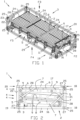
- the device 1 according to the invention represented in figures 1 to 5 comprises a frame 2 in which is stored a composed solar panel 3 in a folded condition.
- the frame 2 in this condition forms a beam-shaped cage 2 around the folded, composed solar panel 3.
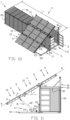
- the solar panel 3 is composed of several solar panels 4 which are mutually hinge-mounted by means of hinged joints 5, in such a way that the composed solar panel 3 can be unfolded from the folded state, represented in figures 1 to 5 , into a folded-out state, represented in figures 6 to 11 , whereby in the folded-out state the solar panels 4 extend in a common plane AA' .
- the composed solar panel 3 can be folded from the folded-out state, represented in figures 6 to 11 , into the folded state which is represented in figures 1 to 5 , by hinging the solar panels 4 in relation to one another by means of the hinged joints 5.
- Every solar panel 4 of the composed solar panel 3 is in this case formed of several flat photovoltaic elements 6 provided on a flat support frame 7 made up of cross beams 8 and longitudinal slats 9.
- These flat support frames 7 are mutually pivotally connected by means of the hinged joints 5.
- photovoltaic elements 6 which are surrounded by a frame or the like or in which a frame is integrated and whereby the hinged joints 5 can be provided directly on said frame.
- every such hinged joint 5 has a common round hinge pin 10 extending parallel to the longitudinal slats 9.
- each cross beam 8 such a hinged joint 5 is also provided with a pair of hinge leaves 11 coupled to one another by means of the hinge pin 10.
- Every hinge leaf 11 of such a pair is connected to a cross beam 8 of one of the support frames 7 to be coupled by the hinged joint 5 concerned.
- the device 1 is provided with three rectangular solar panels 3, but it is not excluded according to the invention to use more or less solar panels 3.
- an intermediate solar panel 12 is provided in this case which is hinge-mounted to an adjacent solar panel 14 or 15 on both longitudinal sides 13.
- the adjacent solar panel 14 is hereinafter referred to as the top solar panel 14, because it is intended to be positioned, in an inclined position of the folded-out, composed solar panel 3, above the intermediate solar panel 12, as is represented for example in figures 8 to 11 .
- the adjacent solar panel 15 is hereinafter referred to as the bottom solar panel 15, as it is positioned under the intermediate solar panel 12 in the same inclined position of the folded-out, composed solar panel 3.
- the hinged joints 5 of the composed solar panel 3 are such that the intermediate solar panel 12 can rotate forward to the top solar panel 14, such that the photovoltaic elements 6 of the solar panels 12 and 14 concerned, in the folded state of the composed solar panel 3, are adjacent to one another.
- the bottom solar panel 15 can rotate backwards to the intermediate solar panel 12, such that the support frames 7 of the solar panels 12 and 15 concerned, in the folded state of the composed solar panel 3, are adjacent to one another.
- the frame 2 of the device 1 is composed of two frame portions 16 and 17 which can be disassembled, more specifically a first frame portion 16 and a second frame portion 17.
- each frame portion 16 and 17 forms a supporting structure for the folded-out, composed solar panel 3, as is represented in figures 6 to 11 .
- first frame portion 16 and the second frame portion 17 contain a base 18 extending in a plane, whereby this base 18 forms either the bottom surface 19 or the upper surface 20 respectively of the beam-shaped cage 2, at least when the frame 2 is assembled into a cage 2.
- each frame portion 16 and 17 contains a number of standing ribs, ribs 21 and 22 respectively, extending crosswise to the corresponding base 18.
- the first frame portion 16 is provided with three such standing ribs 21, whereas the second frame portion 17 is provided with only two such standing ribs 22.
- standing ribs 21 or 22 can be provided forming a row of adjacent, standing ribs 21 and 22 between the bottom surface 19 and the upper surface 20 of the frame 2 in its assembled condition.
- a fixed panel may be provided in the plane of the standing ribs 21 and 22 in order to reduce the wind loads on the composed solar panel 3.
- standing ribs 21 and 22 may vary.
- the base 18 in this case forms a rectangular frame 18 which is composed of longitudinal beams 23 and cross beams 24 which are connected in the corners to the corresponding standing rib 21 or 22 by means of corner pieces 25.
- the corner pieces 25 are preferably of a type which is used as standard in a so-called ISO container 26 for transporting goods, an example of which is represented in figures 6 to 11 .
- holes 27 are provided in three mutually perpendicular planes which are used in the transport sector in order to be able to lift the containers 26 with so-called “twist locks” or in order to link several containers 26.
- the frame 2 or the frame portions 16 and 17 can also be easily manipulated with the same hoist means as the standard ISO containers 26, or the device 1 can be easily linked to such a standard ISO container 26.
- connection pieces 28 In support of the standing ribs 21 and 22 are provided slanting connection pieces 28 between the standing rib 21 or 22 concerned and the base 18.
- the frame 2 is hinge-mounted to the composed solar panel 3, more specifically at the longitudinal side 13 of the intermediate solar panel 12 which is adjacent to the top solar panel 14.
- the composed solar panel 3 is thereby hinge-mounted to the first frame portion 16 containing the bottom surface 19 of the beam-shaped cage 2, namely on the longitudinal side 29 of said bottom surface 19 opposite the pair of standing ribs 21 of the first frame portion 16 concerned.
- the composed solar panel 3 can be unfolded into its folded-out state by folding apart the solar panels 3 with respect to each other.
- the length L of the composed solar panel 3 should of course be somewhat smaller than the length L' of the frame 2.
- the composed solar panel 3 can be rotated as a whole in its folded-out state, preferably gradually, with respect to the first frame portion 16, such that it can be oriented, for example in a horizontal position, as is represented in figures 6 and 7 , or in an inclined position, as is represented in figures 8 to 11 , in an oblique position at an angle X of 15° in relation to the horizontal plane ZZ' for figures 8 and 9 , and in an inclined position at an angle Y of 30° in relation to the horizontal plane ZZ' respectively.
- the frame portions 16 and 17 are designed to be gradually erected in support of the folded-out, composed solar panel 3, whereby each frame portion 16 and 17 is placed with its base 18 on a flat surface or on the surface of a supporting structure.
- the first frame portion 16 is designed to support the composed solar panel 3 by putting it with its base 18 in a position at a certain height H above a flat surface 19 on which the other second frame portion 17 is placed with its base 18 in order to support the composed solar panel 3.
- the supporting structure consists of a container 26, but in other cases also other supporting structures can be applied of course.
- the frame 2 is hereby implemented with the right dimensions, such that it fits on the roof 30 of the container 26.
- the frame 2 has a length L' equal to half the length L" of the container 26, such that two devices 1 can be lined up on the roof 30 of the container 26.
- the frame 2 in this case has a width B which is equal to the width B of the container 26.
- Putting up composed solar panels 3 may be simply done in practice by disassembling the frames 2 concerned and then turning the second frame portions 17 around, such that they can be put up on the ground with their base 18 next to the respective containers 26, which is illustrated by way of example in figures 6 to 11 .
- a first frame portion 16 can be suspended with the composed solar panel 3 between a pair of containers 26 arranged in succession, more specifically by hanging this first frame portion 16 on either side to first frame portions 16 which are placed on the roof 30 of the successive containers 26 concerned.
- the first frame portions 16 can hereby be connected to each other by making use of twist-locks provided in the corner pieces 25.
- the second frame portion 17 can be placed on the ground between the containers 26 and it can possibly be coupled to the adjacent frame portions 17.
- the devices 1 may be modularly built and combined to form a larger unit.
- the second frame portion 17 is provided with adjusting means 31 which connect the second frame portion 17 concerned to the composed solar panel 3 and with which the distance D between the folded-out, composed solar panel 3 and the second frame portion 17 concerned can be adjusted in order to orient the folded-out, composed solar panel 3.
- these adjusting means 31 comprise a cylinder 32 and an electric spindle 33, as well as an electric control 34, with which the above-mentioned distance D can be set between the second frame portion 17 and the folded-out, composed solar panel 3.
- the control 34 may for example also comprise detection means with which it is possible to detect in what direction the incident light has the most intensity, such that based on these measurements the folded-out, composed solar panel 3 can be automatically put in a position crosswise to this direction with the largest light intensity by setting the distance D correctly.
- the composed solar panel 3 may for example also be automatically put in the horizontal position by the control 34 in case of too high wind speeds or snowfall, for example.
- the adjusting means 31 and control 34 may also have other shapes.
- the adjusting means 31 can also be stored in the frame 2 in the condition wherein it forms a cage 2 for the folded, composed solar panel 3.
- the photovoltaic elements 6 and solar panels 4 are pre-wired and pre-connected to one another by the appropriate connecting means 35, such that the composed solar panel 3 can be put into operation as an electrical power supply by simply arranging the frame portions 16 and 17 correctly, folding out the composed solar panel 3 and putting it in the right position in relation to the sun.
Landscapes
- Engineering & Computer Science (AREA)
- Physics & Mathematics (AREA)
- Life Sciences & Earth Sciences (AREA)
- Sustainable Development (AREA)
- Sustainable Energy (AREA)
- Thermal Sciences (AREA)
- Chemical & Material Sciences (AREA)
- Combustion & Propulsion (AREA)
- Mechanical Engineering (AREA)
- General Engineering & Computer Science (AREA)
- Photovoltaic Devices (AREA)
Claims (12)
- Vorrichtung (1), umfassend mehrere Solarmodule (4), wobei die Solarmodule (4) mit Scharnieren aneinander montiert sind, so dass sie derart ein zusammengesetztes Solarmodul (3) bilden, dass das zusammengesetzte Solarmodul (3) von einem ausgeklappten Zustand in einen zusammengeklappten Zustand, in dem die Solarmodule (4) aneinander angrenzen, geklappt werden kann, und dass das zusammengesetzte Solarmodul (3) von einem zusammengeklappten Zustand in einen ausgeklappten Zustand aufgeklappt werden kann, in dem sich die Solarmodule (4) in einer gemeinsamen Ebene (AA') erstrecken, wobei die Vorrichtung (1) ferner mit einem Rahmen (2) versehen ist, der mit einem Scharnier an dem zusammengesetzten Solarmodul (3) montiert und aus zwei Rahmenabschnitten (16, 17) gebildet ist, die auseinandergebaut werden können, insbesondere einem ersten Rahmenabschnitt (16) und einem zweiten Rahmenabschnitt (17), dadurch gekennzeichnet, dass der zweite Rahmenabschnitt (17) mit Einstellmitteln (31) versehen ist, die den zweiten betreffenden Rahmenabschnitt (17) mit dem zusammengesetzten Solarmodul (3) verbinden, und wobei beide Rahmenabschnitte (16, 17) eine Basis (18) enthalten, die sich in einer Ebene erstreckt und eine Anzahl von stehenden Rippen (21) bzw. (22) enthält, die sich quer zur entsprechenden Basis (18) erstrecken, wobei in einem auseinandergebauten Zustand des Rahmens (2) jeder Rahmenabschnitt (16, 17) eine Trägerstruktur für das Solarmodul (3) bildet, die in ihren ausgeklappten Zustand aufgeklappt werden kann, indem die Solarmodule (4) zueinander aufgeklappt werden, und wobei das zusammengesetzte Solarmodul (3) als Ganzes in dem ausgeklappten Zustand in Bezug auf den ersten Rahmenabschnitt (16), an dem es mit einem Scharnier montiert ist, gedreht werden kann, um es in einer horizontalen Position und/oder in beliebigen schrägen Positionen auszurichten, wobei der Rahmen (2) in einem zusammengebauten Zustand einen balkenförmigen Käfig (2) um das zusammengeklappte, zusammengesetzte Solarmodul (3) bildet, wobei die Basis (18) jeweils entweder die untere Oberfläche (19) oder die obere Oberfläche (20) des balkenförmigen Käfigs (2) zumindest dann bildet, wenn der Rahmen (2) zu einem Käfig (2) zusammengebaut ist.
- Vorrichtung (1) nach Anspruch 1, dadurch gekennzeichnet, dass die Solarmodule (4) aus einem oder mehreren flachen Photovoltaikelementen (6) gebildet sind, die auf einem flachen Trägerrahmen (7) vorgesehen sind, und wobei diese flachen Trägerrahmen (7) durch ein Scharnier aneinander montiert sind.
- Vorrichtung (1) nach Anspruch 1 oder 2, dadurch gekennzeichnet, dass die Vorrichtung (1) mit drei rechteckigen Solarmodulen (4), insbesondere einem Zwischensolarmodul (12), versehen ist, das an beiden Längsseiten (13) mit einem Scharnier an einem angrenzenden Solarmodul (14, 15), insbesondere an einem oberen Solarmodul (14) einerseits und an einem unteren Solarmodul (15) andererseits montiert ist, die dazu gestaltet sind, in einer schrägen Position des ausgeklappten, zusammengesetzten Solarmoduls (3) über bzw. unter dem Zwischensolarmodul (12) positioniert zu werden.
- Vorrichtung (1) nach Anspruch 3, dadurch gekennzeichnet, dass das Zwischensolarmodul (12) vorwärts zum oberen Solarmodul (14) hin gedreht werden kann, so dass die Photovoltaikelemente (6) der betreffenden Solarmodule (14) im zusammengeklappten Zustand des zusammengesetzten Solarmoduls (3) aneinander angrenzen, und wobei das untere Solarmodul (15) rückwärts zum Zwischensolarmodul (12) hin gedreht werden kann, so dass die Trägerrahmen (7) der betreffenden Solarmodule (4) im zusammengeklappten Zustand des zusammengesetzten Solarmoduls (3) aneinander angrenzen.
- Vorrichtung (1) nach Anspruch 3 oder 4, dadurch gekennzeichnet, dass das zusammengesetzte Solarmodul (3) mit einem Scharnier auf der Längsseite (13) des Zwischensolarmoduls (12), das an das obere Solarmodul (14) angrenzt, an dem Rahmen (2) montiert ist.
- Vorrichtung (1) nach einem oder mehreren der vorhergehenden Ansprüche, dadurch gekennzeichnet, dass im auseinandergebauten Zustand des Rahmens (2) das zusammengesetzte Solarmodul (3) in seinen ausgeklappten Zustand aufgeklappt werden kann, indem die Solarmodule (4) in Bezug zueinander aufgeklappt werden, und wobei das zusammengesetzte Solarmodul (3) als Ganzes im ausgeklappten Zustand in Bezug auf den ersten Rahmenabschnitt (16), an dem es mit einem Scharnier montiert ist, gedreht werden kann, um es in einer horizontalen Position und/oder in beliebigen schrägen Positionen auszurichten.
- Vorrichtung (1) nach einem oder mehreren der vorhergehenden Ansprüche, dadurch gekennzeichnet, dass der erste Rahmenabschnitt (16) und der zweite Rahmenabschnitt (17) eine Basis (18) enthalten, die sich in einer Ebene erstreckt, wobei diese Basis (18) jeweils entweder die untere Oberfläche (19) oder die obere Oberfläche (20) des balkenförmigen Käfigs (2) bildet, und wobei die Rahmenabschnitte (16, 17) ferner eine Anzahl von stehenden Rippen (21, 22) umfassen, die sich quer zur entsprechenden Basis (18) erstrecken, und wobei die stehenden Rippen (21, 22) im zusammengebauten Zustand eine Reihe von angrenzenden, stehenden Rippen (21, 22) zwischen der oberen Oberfläche (20) und der unteren Oberfläche (19) des Rahmens (2) bilden.
- Vorrichtung (1) nach einem oder mehreren der vorhergehenden Ansprüche, dadurch gekennzeichnet, dass die Rahmenabschnitte (16, 17) dafür gestaltet sind, als Träger des ausgeklappten, zusammengesetzten Solarmoduls (3) allmählich aufgerichtet zu werden, wobei jeder Rahmenabschnitt (16, 17) mit seiner Basis (18) auf einer flachen Oberfläche oder einer Ebene einer Trägerstruktur platziert wird.
- Vorrichtung (1) nach den Ansprüchen 6 und 8, dadurch gekennzeichnet, dass das zusammengesetzte Solarmodul (3) mit einem Scharnier an dem ersten Rahmenabschnitt (16) montiert ist, der die untere Oberfläche (19) des balkenförmigen Käfigs (2) enthält, nämlich auf der Längsseite (29) dieser unteren Oberfläche (19) gegenüber den stehenden Rippen (21) des ersten betreffenden Rahmenabschnitts (16), wobei dieser erste Rahmenabschnitt (16) dafür gestaltet ist, das zusammengesetzte Solarmodul (3) zu tragen, indem es mit seiner Basis (18) in einer Position platziert wird, die sich in einer bestimmten Höhe (H) über einer flachen Oberfläche befindet, auf der der andere, zweite Rahmenabschnitt (17) mit seiner Basis platziert ist, um das zusammengesetzte Solarmodul (3) zu tragen.
- Vorrichtung nach einem oder mehreren der vorhergehenden Ansprüche, dadurch gekennzeichnet, dass mit den Einstellmitteln (31) der Abstand (D) zwischen dem ausgeklappten, zusammengesetzten Solarmodul (3) und dem zweiten betreffenden Rahmenabschnitt (17) so eingestellt werden kann, dass es möglich ist, das ausgeklappte zusammengesetzte Solarmodul (3) auszurichten.
- Vorrichtung (1) nach Anspruch 10, dadurch gekennzeichnet, dass die Einstellmittel (31) einen Zylinder (32) und eine Spindel (33) sowie eine Steuerung (34) von diesen umfassen, mit der der vorstehend erwähnte Abstand (D) zwischen dem zweiten Rahmenabschnitt (17) und dem ausgeklappten, zusammengesetzten Solarmodul (3) eingestellt werden kann, und wobei die Einstellmittel (31) auch in dem Zustand in dem Rahmen (2) gelagert werden können, in dem er einen Käfig (2) für das zusammengeklappte, zusammengesetzte Solarmodul (3) bildet.
- Vorrichtung (1) nach einem oder mehreren der Ansprüche 8 bis 11, dadurch gekennzeichnet, dass sie einen Container (26) umfasst und dass der Rahmen (2) auf das Dach (30) des Containers (26) passt, wobei im zusammengebauten Zustand des Rahmens (2) ein Käfig auf dem Dach (30) des Containers (26) gebildet ist, in dem das zusammengeklappte zusammengesetzte Solarmodul (3) gelagert ist, wobei im auseinandergebauten Zustand des Rahmens (2) der zweite Rahmenabschnitt (17) auf dem Boden neben dem Container (26) platziert ist, während der erste Rahmenabschnitt (16) auf dem Dach (30) des Containers (26) ruht, und wobei das zusammengesetzte Solarmodul (3) in diesem Zustand des Rahmens (2) durch gelenkiges Lagern der Solarmodule (4) in Bezug zueinander ausgeklappt werden kann, und wobei das ausgeklappte, zusammengesetzte Solarmodul (3) gedreht werden kann, um es zwischen einer horizontalen Position und/oder einer beliebigen schrägen Position auszurichten.
Applications Claiming Priority (2)
| Application Number | Priority Date | Filing Date | Title |
|---|---|---|---|
| BE2015/5262A BE1022801B1 (nl) | 2015-04-21 | 2015-04-21 | Inrichting die meerdere zonnepanelen bevat |
| PCT/IB2016/052148 WO2016170455A1 (en) | 2015-04-21 | 2016-04-15 | Foldable device containing several solar panels |
Publications (3)
| Publication Number | Publication Date |
|---|---|
| EP3286832A1 EP3286832A1 (de) | 2018-02-28 |
| EP3286832B1 true EP3286832B1 (de) | 2024-11-13 |
| EP3286832C0 EP3286832C0 (de) | 2024-11-13 |
Family
ID=53938016
Family Applications (1)
| Application Number | Title | Priority Date | Filing Date |
|---|---|---|---|
| EP16724971.3A Active EP3286832B1 (de) | 2015-04-21 | 2016-04-15 | Faltbare vorrichtung mit mehreren sonnenkollektoren |
Country Status (5)
| Country | Link |
|---|---|
| EP (1) | EP3286832B1 (de) |
| BE (1) | BE1022801B1 (de) |
| ES (1) | ES2998508T3 (de) |
| WO (1) | WO2016170455A1 (de) |
| ZA (1) | ZA201707820B (de) |
Families Citing this family (6)
| Publication number | Priority date | Publication date | Assignee | Title |
|---|---|---|---|---|
| EP3527909A1 (de) * | 2018-02-16 | 2019-08-21 | W. Giertsen AS | Montagesystem zur montage von fotovoltaikpaneelen und verfahren zur herstellung eines montagesystems zur montage von fotovoltaikpaneelen |
| CN110722992B (zh) * | 2019-11-25 | 2024-03-29 | 哈尔滨市恩光川川科技有限责任公司 | 一种平行四杆伸缩式车载太阳能充电装置 |
| CN111396253B (zh) * | 2020-04-16 | 2022-09-13 | 海略(连云港)科技有限公司 | 一种近海清洁能源漂浮发电船 |
| FR3112253B1 (fr) * | 2020-07-06 | 2022-07-29 | Ecosun Innovations | Châssis pour panneaux solaires déployables, agençable au-dessus d’un élément modulaire de type container. |
| EP4283213A1 (de) * | 2022-05-24 | 2023-11-29 | Real Verhuur | Mobiles solarenergieerfassungsmodul |
| CN118740004B (zh) * | 2024-09-03 | 2024-12-20 | 中碳科技(洛阳)有限公司 | 一种光伏一体化储能装置及使用方法 |
Citations (5)
| Publication number | Priority date | Publication date | Assignee | Title |
|---|---|---|---|---|
| US20030127125A1 (en) * | 2002-01-04 | 2003-07-10 | Chenming Mold Ind. Corp. | Backup power supply apparatus |
| WO2008083219A2 (en) * | 2006-12-27 | 2008-07-10 | Dennis Mcguire | Portable, self-sustaining power station |
| US20100206354A1 (en) * | 2009-02-16 | 2010-08-19 | Greene Jr James Irvine | Portable Power System |
| AT509886A4 (de) * | 2010-06-29 | 2011-12-15 | Alexander Swatek | Solarmodul |
| US20130186450A1 (en) * | 2012-01-23 | 2013-07-25 | Seldon Energy Partners, LLC | Solar Power System |
Family Cites Families (9)
| Publication number | Priority date | Publication date | Assignee | Title |
|---|---|---|---|---|
| JPH05308147A (ja) * | 1992-04-30 | 1993-11-19 | Nippon Hoso Kyokai <Nhk> | 可搬型太陽電池ユニット |
| CA2787711A1 (en) * | 2010-01-20 | 2011-07-28 | University Of Houston | Versatile unfolding solar deployment system |
| US8854794B2 (en) * | 2010-01-21 | 2014-10-07 | George Van Straten | Mobile electricity generator using solar panels |
| WO2011128463A1 (es) * | 2010-04-13 | 2011-10-20 | Tempero 2000 S.L. | Central energética transportable |
| US20130082637A1 (en) * | 2011-09-30 | 2013-04-04 | Day and Night Solar, LLC | Portable solar panel power source |
| ITRM20110561A1 (it) * | 2011-10-25 | 2013-04-26 | Pro D3 S R L | Gruppo elettrogeno solare mobile a pannelli dispiegantisi |
| FR2988505B1 (fr) * | 2012-03-22 | 2014-04-25 | Atermes | Balise de surveillance |
| AT513032B1 (de) * | 2012-09-04 | 2014-01-15 | HBT ENERGIETECHNIK GmbH | Multifunktionales, transportables Gebäude |
| US9612039B2 (en) * | 2013-05-14 | 2017-04-04 | Mobile Grid, Llc | Mobile solar power rack |
-
2015
- 2015-04-21 BE BE2015/5262A patent/BE1022801B1/nl active
-
2016
- 2016-04-15 EP EP16724971.3A patent/EP3286832B1/de active Active
- 2016-04-15 ES ES16724971T patent/ES2998508T3/es active Active
- 2016-04-15 WO PCT/IB2016/052148 patent/WO2016170455A1/en not_active Ceased
-
2017
- 2017-11-17 ZA ZA2017/07820A patent/ZA201707820B/en unknown
Patent Citations (5)
| Publication number | Priority date | Publication date | Assignee | Title |
|---|---|---|---|---|
| US20030127125A1 (en) * | 2002-01-04 | 2003-07-10 | Chenming Mold Ind. Corp. | Backup power supply apparatus |
| WO2008083219A2 (en) * | 2006-12-27 | 2008-07-10 | Dennis Mcguire | Portable, self-sustaining power station |
| US20100206354A1 (en) * | 2009-02-16 | 2010-08-19 | Greene Jr James Irvine | Portable Power System |
| AT509886A4 (de) * | 2010-06-29 | 2011-12-15 | Alexander Swatek | Solarmodul |
| US20130186450A1 (en) * | 2012-01-23 | 2013-07-25 | Seldon Energy Partners, LLC | Solar Power System |
Also Published As
| Publication number | Publication date |
|---|---|
| EP3286832A1 (de) | 2018-02-28 |
| ES2998508T3 (en) | 2025-02-20 |
| WO2016170455A1 (en) | 2016-10-27 |
| EP3286832C0 (de) | 2024-11-13 |
| BE1022801B1 (nl) | 2016-09-08 |
| ZA201707820B (en) | 2019-04-24 |
Similar Documents
| Publication | Publication Date | Title |
|---|---|---|
| EP3286832B1 (de) | Faltbare vorrichtung mit mehreren sonnenkollektoren | |
| KR102456022B1 (ko) | 휴대용 태양광 전지 어레이 | |
| US20230179141A1 (en) | Foldable solar power system | |
| US11241799B2 (en) | Solar energy array robotic assembly | |
| US7105940B2 (en) | Mobile renewable energy generator | |
| CN104145166B (zh) | 移动式发电装置和冷却系统 | |
| ES2963059T3 (es) | Matriz fotovoltaica solar portátil | |
| US20190214937A1 (en) | Modular photovoltaic light and power cube | |
| US20230105424A1 (en) | Mobile autonomous solar- wind electrical station | |
| US11047598B2 (en) | Single axis solar tracking assembly and method of installing such single axis solar tracking assembly | |
| US20080264467A1 (en) | Transportable System for Producing Solar Electricity | |
| US11108354B2 (en) | Portable power generator | |
| KR102012511B1 (ko) | 포스트용 분할형 지지장치 | |
| CA2788767A1 (en) | Mobile solar power-generating system | |
| TW201432119A (zh) | 具有太陽能追日裝置之建築物體 | |
| AU2017233070A1 (en) | Solar PV shade-adaptive system and assembly | |
| KR20200111388A (ko) | 태양광 발전모듈 레일 스텐딩 방식의 패키지형 이동식 태양광 발전시스템 | |
| OA18682A (en) | Foldable device containing several solar panels | |
| KR20220082216A (ko) | 컨테이너구조의 이동형 태양광 발전장치 | |
| WO2025208935A1 (en) | Adjustable solar bracket | |
| IT202400000916U1 (it) | Tavolo solare | |
| ES2377794A1 (es) | Equipo autónomo de generación de energía solar fotovoltaica con estructura transportable, plegable y de inclinación variable. |
Legal Events
| Date | Code | Title | Description |
|---|---|---|---|
| STAA | Information on the status of an ep patent application or granted ep patent |
Free format text: STATUS: THE INTERNATIONAL PUBLICATION HAS BEEN MADE |
|
| PUAI | Public reference made under article 153(3) epc to a published international application that has entered the european phase |
Free format text: ORIGINAL CODE: 0009012 |
|
| STAA | Information on the status of an ep patent application or granted ep patent |
Free format text: STATUS: REQUEST FOR EXAMINATION WAS MADE |
|
| 17P | Request for examination filed |
Effective date: 20171121 |
|
| AK | Designated contracting states |
Kind code of ref document: A1 Designated state(s): AL AT BE BG CH CY CZ DE DK EE ES FI FR GB GR HR HU IE IS IT LI LT LU LV MC MK MT NL NO PL PT RO RS SE SI SK SM TR |
|
| AX | Request for extension of the european patent |
Extension state: BA ME |
|
| DAV | Request for validation of the european patent (deleted) | ||
| DAX | Request for extension of the european patent (deleted) | ||
| RIC1 | Information provided on ipc code assigned before grant |
Ipc: F24J 2/54 20181130ALI20161101BHEP Ipc: H02S 20/00 20140101AFI20161101BHEP Ipc: H02S 30/20 20140101ALI20161101BHEP |
|
| RIC1 | Information provided on ipc code assigned before grant |
Ipc: F24J 2/54 20060101ALI20161101BHEP Ipc: H02S 30/20 20140101ALI20161101BHEP Ipc: H02S 20/00 20140101AFI20161101BHEP |
|
| STAA | Information on the status of an ep patent application or granted ep patent |
Free format text: STATUS: EXAMINATION IS IN PROGRESS |
|
| 17Q | First examination report despatched |
Effective date: 20191014 |
|
| 19U | Interruption of proceedings before grant |
Effective date: 20190629 |
|
| 19W | Proceedings resumed before grant after interruption of proceedings |
Effective date: 20201001 |
|
| RAP1 | Party data changed (applicant data changed or rights of an application transferred) |
Owner name: DIRKX, GEERT |
|
| RAP1 | Party data changed (applicant data changed or rights of an application transferred) |
Owner name: OGD TECH S.A.S. |
|
| GRAP | Despatch of communication of intention to grant a patent |
Free format text: ORIGINAL CODE: EPIDOSNIGR1 |
|
| STAA | Information on the status of an ep patent application or granted ep patent |
Free format text: STATUS: GRANT OF PATENT IS INTENDED |
|
| RIC1 | Information provided on ipc code assigned before grant |
Ipc: F24S 25/10 20180101ALI20240513BHEP Ipc: F24S 25/70 20180101ALI20240513BHEP Ipc: H02S 30/20 20140101ALI20240513BHEP Ipc: H02S 20/00 20140101AFI20240513BHEP |
|
| INTG | Intention to grant announced |
Effective date: 20240605 |
|
| GRAS | Grant fee paid |
Free format text: ORIGINAL CODE: EPIDOSNIGR3 |
|
| GRAA | (expected) grant |
Free format text: ORIGINAL CODE: 0009210 |
|
| STAA | Information on the status of an ep patent application or granted ep patent |
Free format text: STATUS: THE PATENT HAS BEEN GRANTED |
|
| AK | Designated contracting states |
Kind code of ref document: B1 Designated state(s): AL AT BE BG CH CY CZ DE DK EE ES FI FR GB GR HR HU IE IS IT LI LT LU LV MC MK MT NL NO PL PT RO RS SE SI SK SM TR |
|
| REG | Reference to a national code |
Ref country code: GB Ref legal event code: FG4D |
|
| REG | Reference to a national code |
Ref country code: CH Ref legal event code: EP |
|
| REG | Reference to a national code |
Ref country code: DE Ref legal event code: R096 Ref document number: 602016090223 Country of ref document: DE |
|
| REG | Reference to a national code |
Ref country code: IE Ref legal event code: FG4D |
|
| U01 | Request for unitary effect filed |
Effective date: 20241113 |
|
| U07 | Unitary effect registered |
Designated state(s): AT BE BG DE DK EE FI FR IT LT LU LV MT NL PT RO SE SI Effective date: 20241128 |
|
| REG | Reference to a national code |
Ref country code: ES Ref legal event code: FG2A Ref document number: 2998508 Country of ref document: ES Kind code of ref document: T3 Effective date: 20250220 |
|
| PG25 | Lapsed in a contracting state [announced via postgrant information from national office to epo] |
Ref country code: HR Free format text: LAPSE BECAUSE OF FAILURE TO SUBMIT A TRANSLATION OF THE DESCRIPTION OR TO PAY THE FEE WITHIN THE PRESCRIBED TIME-LIMIT Effective date: 20241113 Ref country code: IS Free format text: LAPSE BECAUSE OF FAILURE TO SUBMIT A TRANSLATION OF THE DESCRIPTION OR TO PAY THE FEE WITHIN THE PRESCRIBED TIME-LIMIT Effective date: 20250313 |
|
| PG25 | Lapsed in a contracting state [announced via postgrant information from national office to epo] |
Ref country code: NO Free format text: LAPSE BECAUSE OF FAILURE TO SUBMIT A TRANSLATION OF THE DESCRIPTION OR TO PAY THE FEE WITHIN THE PRESCRIBED TIME-LIMIT Effective date: 20250213 |
|
| PG25 | Lapsed in a contracting state [announced via postgrant information from national office to epo] |
Ref country code: GR Free format text: LAPSE BECAUSE OF FAILURE TO SUBMIT A TRANSLATION OF THE DESCRIPTION OR TO PAY THE FEE WITHIN THE PRESCRIBED TIME-LIMIT Effective date: 20250214 |
|
| PG25 | Lapsed in a contracting state [announced via postgrant information from national office to epo] |
Ref country code: PL Free format text: LAPSE BECAUSE OF FAILURE TO SUBMIT A TRANSLATION OF THE DESCRIPTION OR TO PAY THE FEE WITHIN THE PRESCRIBED TIME-LIMIT Effective date: 20241113 |
|
| PG25 | Lapsed in a contracting state [announced via postgrant information from national office to epo] |
Ref country code: RS Free format text: LAPSE BECAUSE OF FAILURE TO SUBMIT A TRANSLATION OF THE DESCRIPTION OR TO PAY THE FEE WITHIN THE PRESCRIBED TIME-LIMIT Effective date: 20250213 |
|
| U20 | Renewal fee for the european patent with unitary effect paid |
Year of fee payment: 10 Effective date: 20250425 |
|
| PG25 | Lapsed in a contracting state [announced via postgrant information from national office to epo] |
Ref country code: SM Free format text: LAPSE BECAUSE OF FAILURE TO SUBMIT A TRANSLATION OF THE DESCRIPTION OR TO PAY THE FEE WITHIN THE PRESCRIBED TIME-LIMIT Effective date: 20241113 |
|
| PGFP | Annual fee paid to national office [announced via postgrant information from national office to epo] |
Ref country code: ES Payment date: 20250512 Year of fee payment: 10 |
|
| U1N | Appointed representative for the unitary patent procedure changed after the registration of the unitary effect |
Representative=s name: BONCEA, OANA-LAURA; LU |
|
| PG25 | Lapsed in a contracting state [announced via postgrant information from national office to epo] |
Ref country code: SK Free format text: LAPSE BECAUSE OF FAILURE TO SUBMIT A TRANSLATION OF THE DESCRIPTION OR TO PAY THE FEE WITHIN THE PRESCRIBED TIME-LIMIT Effective date: 20241113 |
|
| PGFP | Annual fee paid to national office [announced via postgrant information from national office to epo] |
Ref country code: TR Payment date: 20250402 Year of fee payment: 10 |
|
| PG25 | Lapsed in a contracting state [announced via postgrant information from national office to epo] |
Ref country code: CZ Free format text: LAPSE BECAUSE OF FAILURE TO SUBMIT A TRANSLATION OF THE DESCRIPTION OR TO PAY THE FEE WITHIN THE PRESCRIBED TIME-LIMIT Effective date: 20241113 |
|
| PLBE | No opposition filed within time limit |
Free format text: ORIGINAL CODE: 0009261 |
|
| STAA | Information on the status of an ep patent application or granted ep patent |
Free format text: STATUS: NO OPPOSITION FILED WITHIN TIME LIMIT |
|
| 26N | No opposition filed |
Effective date: 20250814 |
|
| REG | Reference to a national code |
Ref country code: CH Ref legal event code: H13 Free format text: ST27 STATUS EVENT CODE: U-0-0-H10-H13 (AS PROVIDED BY THE NATIONAL OFFICE) Effective date: 20251125 |
|
| PG25 | Lapsed in a contracting state [announced via postgrant information from national office to epo] |
Ref country code: MC Free format text: LAPSE BECAUSE OF FAILURE TO SUBMIT A TRANSLATION OF THE DESCRIPTION OR TO PAY THE FEE WITHIN THE PRESCRIBED TIME-LIMIT Effective date: 20241113 |
|
| GBPC | Gb: european patent ceased through non-payment of renewal fee |
Effective date: 20250415 |
|
| PG25 | Lapsed in a contracting state [announced via postgrant information from national office to epo] |
Ref country code: GB Free format text: LAPSE BECAUSE OF NON-PAYMENT OF DUE FEES Effective date: 20250415 |
|
| PG25 | Lapsed in a contracting state [announced via postgrant information from national office to epo] |
Ref country code: CH Free format text: LAPSE BECAUSE OF NON-PAYMENT OF DUE FEES Effective date: 20250430 |
|
| PG25 | Lapsed in a contracting state [announced via postgrant information from national office to epo] |
Ref country code: IE Free format text: LAPSE BECAUSE OF NON-PAYMENT OF DUE FEES Effective date: 20250415 |