EP3287002A1 - Ramasseuse-presse dotée d'une position automatique de position de piston - Google Patents
Ramasseuse-presse dotée d'une position automatique de position de piston Download PDFInfo
- Publication number
- EP3287002A1 EP3287002A1 EP17186366.5A EP17186366A EP3287002A1 EP 3287002 A1 EP3287002 A1 EP 3287002A1 EP 17186366 A EP17186366 A EP 17186366A EP 3287002 A1 EP3287002 A1 EP 3287002A1
- Authority
- EP
- European Patent Office
- Prior art keywords
- plunger
- power take
- speed
- operable
- tractor
- Prior art date
- Legal status (The legal status is an assumption and is not a legal conclusion. Google has not performed a legal analysis and makes no representation as to the accuracy of the status listed.)
- Granted
Links
Images
Classifications
-
- A—HUMAN NECESSITIES
- A01—AGRICULTURE; FORESTRY; ANIMAL HUSBANDRY; HUNTING; TRAPPING; FISHING
- A01F—PROCESSING OF HARVESTED PRODUCE; HAY OR STRAW PRESSES; DEVICES FOR STORING AGRICULTURAL OR HORTICULTURAL PRODUCE
- A01F15/00—Baling presses for straw, hay or the like
- A01F15/04—Plunger presses
- A01F15/042—Plungers
-
- A—HUMAN NECESSITIES
- A01—AGRICULTURE; FORESTRY; ANIMAL HUSBANDRY; HUNTING; TRAPPING; FISHING
- A01F—PROCESSING OF HARVESTED PRODUCE; HAY OR STRAW PRESSES; DEVICES FOR STORING AGRICULTURAL OR HORTICULTURAL PRODUCE
- A01F15/00—Baling presses for straw, hay or the like
- A01F15/08—Details
- A01F15/0841—Drives for balers
-
- A—HUMAN NECESSITIES
- A01—AGRICULTURE; FORESTRY; ANIMAL HUSBANDRY; HUNTING; TRAPPING; FISHING
- A01F—PROCESSING OF HARVESTED PRODUCE; HAY OR STRAW PRESSES; DEVICES FOR STORING AGRICULTURAL OR HORTICULTURAL PRODUCE
- A01F15/00—Baling presses for straw, hay or the like
- A01F15/08—Details
- A01F15/0875—Discharge devices
Definitions
- the present invention relates to systems and methods for controlling the operation of balers.
- balers are used in the agricultural industry to create large substantially rectangular bales of crop material by moving over crop windrows to collect loose crop material, compress the material, and form it into bales that are then tied and ejected.
- a baler is typically mechanically coupled with a tractor, and a power take-off (PTO) mechanism transfers power from the tractor's engine to drive the baler's operation.
- a rotary pick-up at the front of the baler picks up the loose crop material and moves it into a stuffer chamber. Once the stuffer chamber is full, its contents are moved through a stuffer chute into a forming chamber.
- a reciprocating plunger compresses the crop material in the forming chamber into a growing bale. Once the bale reaches a predetermined length, which could be eight feet, it is tied and ejected through a discharge outlet to fall onto the ground behind the baler. The process then continues to create the next bale.
- Embodiments of the present invention solve the above-described and other problems and limitations by decreasing the amount of torque required to restart the baler, maximizing the flywheel's momentum when the plunger contacts the bale in the forming chamber, and minimizing the risk of stalling the tractor engine or disengaging the PTO.
- a baling system acts at shut-down to substantially automatically pre-position the plunger so that it is just past a rear-dead-center position when the baler is restarted.
- the baling system may broadly comprise a forming chamber having a discharge outlet, wherein the bale is located in the forming chamber; the plunger operable to move in a reciprocating manner within the forming chamber from a front-dead-center position in which the plunger is furthest from the bale to the rear-dead-center position in which the plunger is closest to the bale; a communication bus extending between the baler and the tractor and operable to transmit electrical signals; a plunger position sensor operable to sense a position of the plunger in the forming chamber; a PTO speed sensor operable to sense a speed of the PTO; and a control unit in communication with the tractor, the plunger position sensor, and the PTO speed sensor, and operable to substantially automatically pre-position the plunger at a
- control unit is further operable to receive a deactivation signal sent by the tractor to the PTO over the communication bus, release a pressure in the forming chamber, repeatedly apply a braking force to the PTO for a first braking interval and remove the braking force for a second braking interval until the PTO has slowed to a predetermined maximum speed based on information received from the PTO speed sensor, and then constantly apply the braking force so that the plunger stops at the predetermined position.
- the baling system may further include any one or more of the following additional features.
- the baling system may further include a crankshaft operable to transfer power from the PTO to the plunger, and wherein the plunger position sensor is mounted on the crankshaft.
- the length of the first braking interval and the length of the second braking interval may both be determined by the speed of the PTO.
- the control unit may be operable to access a look-up table in which is stored the length of the first braking interval and the length of the second braking interval, or the control unit may be further operable to calculate the length of the first braking interval and the length of the second braking interval based on the speed of the PTO.
- the predetermined position of the plunger may be approximately between a rear-dead-center position and the rear-dead-center position plus 10 degrees, or the predetermined position of the plunger may be approximately just after the rear-dead-center position.
- the baling system acts at restart-up to substantially automatically repeatedly activate and deactivate the PTO in order to accelerate the plunger to at least a predetermined minimum operating speed before activating the PTO for continuous operation.
- the baling system may broadly comprise the forming chamber; the plunger; the communication bus; a plunger speed sensor operable to sense a speed of the plunger in the forming chamber; and the control unit in communication with the tractor and the plunger speed sensor, and operable to substantially automatically accelerate the plunger to the predetermined minimum speed after the PTO is activated.
- control unit may be further operable to receive an activation signal sent by the tractor to the PTO over the communication bus, repeatedly activate and deactivate the PTO for an activation interval until the plunger has reached the predetermined minimum speed based on information received from the plunger speed sensor, and then leave the PTO constantly activated for normal operation.
- the baling system may further include any one or more of the following additional features.
- the baling system may further include a crankshaft operable to transfer power from the PTO to the plunger, and wherein the plunger speed sensor is mounted on the crankshaft.
- the length of the activation interval may be determined by the speed of the plunger.
- the control unit may be further operable to access a look-up table in which is stored the length of the activation interval, or the control unit may be further operable to calculate the length of the activation interval based on the speed of the plunger.
- each of these embodiments and implementations may be alternatively characterized as methods based on their functionalities.
- references to “one embodiment”, “an embodiment”, or “embodiments” mean that the feature or features referred to are included in at least one embodiment of the invention.
- references to “one embodiment”, “an embodiment”, or “embodiments” in this description do not necessarily refer to the same embodiment and are not mutually exclusive unless so stated.
- a feature, structure, act, etc. described in one embodiment may also be included in other embodiments, but is not necessarily included.
- particular implementations of the present invention can include a variety of combinations and/or integrations of the embodiments described herein.
- the present invention provides a baling system that decreases the amount of torque required to restart a baler, maximizes a flywheel's momentum when a plunger contacts a bale, and minimizes a risk of stalling a tractor engine or disengaging a PTO.
- the baling system acts at shut-down to substantially automatically pre-position the plunger so that it is just past a rear-dead-center position when the baler is restarted.
- the baling system acts at restart-up to substantially automatically repeatedly activate and deactivate the PTO in order to accelerate the plunger to at least a predetermined minimum operating speed before activating the PTO for continuous operation.
- the first embodiment pre-positions the plunger during shut-down to give the plunger a "running start" at the next restart, and the second embodiment "gooses" the plunger during restart to accelerate it to a minimum operating speed.
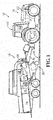
- an embodiment of the baling system 10 is operable to receive loose crop material 12 and form it into a substantially rectangular finished bale 14.
- the baling system 10 may broadly comprise a tractor 16 and a baler 18.
- the tractor 16 may include a cab 20 wherein an operator is located; an engine 22 operable to move the tractor 16; and a PTO 24 operable to transfer mechanical power from the engine 22 to the baler 18 or other connected machinery.
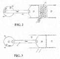
- the baler 18 may broadly comprise a frame 28 mechanically coupled with the tractor 16; a loose crop material receiving component 30; a forming chamber 32; a plunger 34; a crankshaft 36; a flywheel 38; a communication bus 40 extending between the tractor 16 and the baler 18; one or more plunger sensors 44; one or more PTO sensors 46; and an electronic control unit (ECU) 48.
- a frame 28 mechanically coupled with the tractor 16
- a loose crop material receiving component 30 a forming chamber 32
- a plunger 34 a crankshaft 36
- a flywheel 38 a communication bus 40 extending between the tractor 16 and the baler 18
- one or more plunger sensors 44 one or more PTO sensors 46
- ECU electronic control unit
- the loose crop material receiving component 30 may be operable to collect loose crop material 12 from the ground for baling.
- the loose crop material receiving component 30 may include an arbor component operable to pick up the loose crop material 12 from the ground, a cutter component operable to cut the collected loose crop material 12, and a feeder component operable to feed the loose crop material 12 into a stuffer chute connected to the forming chamber 32.
- the forming chamber 32 may be operable to receive loose crop material 12 from the stuffer chute via a stuffer chute inlet, and hold the loose crop material 12 as it is compressed by the plunger 34 into a growing unfinished bale 50.
- the forming chamber 32 may be substantially rectangular in shape to facilitate the compression and forming process.
- the plunger 34 may be operable to compress the loose crop material 12 into the unfinished bale 50 by moving within the forming chamber 32 in a reciprocating manner. More specifically, the plunger 34 repeatedly extends into the forming chamber 32 to compress the loose crop material already present therein, and retracts to allow additional loose crop material to enter via the stuffer chute inlet.
- a connecting rod 52 may connect the plunger 34 to the crankshaft 36.
- the crankshaft 36 may mechanically couple and be operable to transfer power from the PTO 24 to the plunger 34.
- the flywheel 38 may be operable to store and release kinetic energy from the PTO 24 in order to provide greater inertial mass to smooth the operation of the plunger 34.
- the communication bus 40 may be operable to communicate electrical signals bi-directionally between the tractor 16 and the baler 18, especially the ECU 48, to facilitate baling operations.
- the communication bus 40 may be a controller area network (CAN).
- the communication bus 40 may include a wire connection or a wireless connection between the tractor 16 and the baler 18.
- the one or more plunger sensors 44 may be operable to determine or provide information to the ECU 48 for determining a position and a speed of the plunger 34 as it moves within the forming chamber 32.
- the one or more plunger sensors 44 may be mounted on the crankshaft 36, wherein the rotational speed of the crankshaft 36 is at least reflective of the speed of the PTO 24 and equivalent to the speed of the plunger 34.
- the one or more PTO sensors 46 may be operable to determine or provide information to the ECU 48 for determining a speed of the PTO 24.
- the ECU 48 may be operable to receive input signals from the one or more plunger sensors 44 and the one or more PTO sensors 46 and provide output signals to the various components of the baling system 10 to substantially automatically accomplish, in the first embodiment of the present invention, the pre-positioning of the plunger 34 during shut-down or, in the second embodiment, the acceleration of the plunger 34 during restart-up.
- the baling system 10 may function as follows. In both embodiments, operation begins with an unfinished bale 50 located in the forming chamber 32.
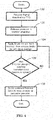
- the present invention acts at shut-down to electronically sense the position and speed of the plunger 34 during deactivation of the PTO 24 and apply a braking force to stop the plunger 34 within a particular range of positions or at a particular position that reduces the torque required when re-starting the system. Referring to Fig.
- the ECU 48 monitors the communication bus 40 for a signal from the tractor 16 which deactivates the PTO 24, and when the ECU 48 receives the deactivation signal, as shown in step 100, the ECU 48 releases the pressure (associated with the compression of the growing bale 50) in the forming chamber 32, as shown in step 102, in order both to ease subsequent restart-up and to make it easier to predict when the plunger 34 will stop.
- the speed of the crankshaft 36 during normal operation may be approximately 50 revolutions per minute, such that the plunger 34 moves from front-dead-center (seen in Fig. 2 ) to rear-dead-center (seen in Fig. 3 ) and back in a little over 1 second.
- the ECU 48 sends a control signal to apply a braking force to the PTO 24 for an on-time braking interval and then deactivates the braking force for an off-time braking interval, as shown in step 104. Both the on-time braking interval and the off-time braking interval may be measured in seconds.
- Both the on-time braking interval and the off-time braking interval may be dependent on the PTO speed, and may be provided in a look-up table stored in a memory accessible by the ECU 48 or may be mathematically determined by the ECU 48 using one or more equations relating the on-time braking interval and the off-time braking interval to PTO speed.
- the on-time and off-time braking intervals may be alternatively or additionally dependent on the plunger speed sensed by the one or more plunger sensors 44.
- the braking force may be a frictional, magnetic, or other force applied to the flywheel 38 or to one or more other components.
- the ECU 48 receives input from the one or more PTO sensors 46 (and/or plunger sensors 44) regarding the speed of the PTO 24 (and/or plunger 34). As necessary, the ECU 48 repeatedly applies the braking force to the PTO 24 for the on-time braking interval and then deactivates it for the off-time braking interval until the PTO 24 (and/or plunger 34) slows to a predetermined maximum speed, as shown in step 106.
- the ECU 48 receives input from the one or more plunger sensors 44 regarding the speed and position of the plunger 34, and once the PTO reaches the pre-determined maximum speed, the ECU 48 constantly applies the braking force to bring the PTO 24 to a stop in such a manner as to bring the plunger 34 to a stop within the range of particular positions or at the particular position, as show in step 108.
- the range of particular positions may be approximately between rear-dead-center and rear-dead-center plus 10 degrees, and the particular position may be approximately just after rear dead center, i.e., just after the plunger 34 has contacted and separated from the bale 50 and is beginning to move away from the bale 50.
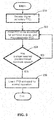
- the present invention acts at start-up to electronically sense the speed of the plunger 34 during activation, and controls activation of the PTO 24 to bring the plunger 34 to at least a predetermined minimum speed that allows for constantly activating the PTO 24 under minimized inertial load.
- the ECU 48 monitors the communication bus 40 for a signal from the tractor 16 which activates the PTO 24, and when the ECU 48 receives the activation signal, as shown in step 200, the ECU 48 allows the PTO 24 to be activated for an on-time activation interval and then the ECU 48 sends a signal to the tractor 16 to deactivate the PTO 44, as shown in step 202.
- the on-time activation interval may be measured in seconds.
- the on-time activation interval is dependent on the speed of the plunger 34, and may be provided in a look-up table stored in a memory accessible by the ECU 48 or may be mathematically determined by the ECU 48 using one or more equations relating the on-time activation interval to plunger speed.
- the ECU 48 receives input from the one or more plunger sensors 44 regarding the speed of the plunger 34, and, as necessary, the ECU 48 repeatedly activates the PTO 24 for the on-time activation interval and then deactivates it until the plunger 34 reaches a predetermined minimum speed, as shown in step 204. Once the plunger 34 reaches the pre-determined minimum speed, the ECU 48 leaves the PTO 24 activated for normal operation, as shown in step 206.
- both the first and second embodiments may be incorporated into the baling system 10, with the first embodiment being used when stopping and the second embodiment being used when starting, or only one of the embodiments may be incorporated into the baling system 10. If only the second embodiment is incorporated into the baling system 10, then the plunger 34 may not be stopped at any particular position when stopping.
- the present invention provides advantages over the prior art, including that it decreases the amount of torque required to restart the baler 18, maximizes the flywheel's momentum when the plunger 34 contacts the bale 50, and minimizes the risk of stalling the tractor engine 22 or disengaging the PTO 24.
Landscapes
- Life Sciences & Earth Sciences (AREA)
- Environmental Sciences (AREA)
- Agricultural Machines (AREA)
Applications Claiming Priority (3)
| Application Number | Priority Date | Filing Date | Title |
|---|---|---|---|
| US201462045311P | 2014-09-03 | 2014-09-03 | |
| PCT/US2015/048217 WO2016036894A1 (fr) | 2014-09-03 | 2015-09-03 | Presse à balles à positionnement automatique du piston |
| EP15763177.1A EP3188585B1 (fr) | 2014-09-03 | 2015-09-03 | Presse à balles à positionnement automatique du piston |
Related Parent Applications (2)
| Application Number | Title | Priority Date | Filing Date |
|---|---|---|---|
| EP15763177.1A Division-Into EP3188585B1 (fr) | 2014-09-03 | 2015-09-03 | Presse à balles à positionnement automatique du piston |
| EP15763177.1A Division EP3188585B1 (fr) | 2014-09-03 | 2015-09-03 | Presse à balles à positionnement automatique du piston |
Publications (2)
| Publication Number | Publication Date |
|---|---|
| EP3287002A1 true EP3287002A1 (fr) | 2018-02-28 |
| EP3287002B1 EP3287002B1 (fr) | 2019-11-13 |
Family
ID=54106022
Family Applications (2)
| Application Number | Title | Priority Date | Filing Date |
|---|---|---|---|
| EP15763177.1A Active EP3188585B1 (fr) | 2014-09-03 | 2015-09-03 | Presse à balles à positionnement automatique du piston |
| EP17186366.5A Active EP3287002B1 (fr) | 2014-09-03 | 2015-09-03 | Ramasseuse-presse dotée d'une position automatique de position de piston |
Family Applications Before (1)
| Application Number | Title | Priority Date | Filing Date |
|---|---|---|---|
| EP15763177.1A Active EP3188585B1 (fr) | 2014-09-03 | 2015-09-03 | Presse à balles à positionnement automatique du piston |
Country Status (5)
| Country | Link |
|---|---|
| US (2) | US10091942B2 (fr) |
| EP (2) | EP3188585B1 (fr) |
| AU (2) | AU2015311984B2 (fr) |
| CA (2) | CA3096090C (fr) |
| WO (1) | WO2016036894A1 (fr) |
Families Citing this family (7)
| Publication number | Priority date | Publication date | Assignee | Title |
|---|---|---|---|---|
| US10058037B2 (en) * | 2014-10-28 | 2018-08-28 | Deere & Company | Baler and method for improved bale handling |
| BE1022803B1 (nl) * | 2015-03-16 | 2016-09-09 | Cnh Industrial Belgium Nv | Baling chamber sensor. |
| US10064339B2 (en) * | 2015-12-02 | 2018-09-04 | Agco Corporation | System and method for controlling bale weight |
| DE102017121090A1 (de) | 2017-09-12 | 2019-03-14 | Usines Claas France S.A.S | Ballenpresse sowie Verfahren zu deren Betrieb |
| US11700792B2 (en) * | 2019-10-25 | 2023-07-18 | Deere & Company | Torque smoothing apparatuses for large square balers |
| EP3818816B1 (fr) * | 2019-11-08 | 2023-09-06 | CNH Industrial Belgium NV | Système agricole |
| SE546636C2 (en) * | 2023-05-23 | 2025-01-07 | Scania Cv Ab | Control arrangement and method for controlling vehicle speed |
Citations (3)
| Publication number | Priority date | Publication date | Assignee | Title |
|---|---|---|---|---|
| US20010042362A1 (en) * | 2000-05-13 | 2001-11-22 | New Holland North America, Inc., A Delaware Corporation | Method and apparatus for controlling a tractor/baler combination |
| US20140165859A1 (en) * | 2012-12-13 | 2014-06-19 | Agco Corporation | Square baler having flywheel planetary drive |
| WO2014128100A1 (fr) * | 2013-02-21 | 2014-08-28 | Cnh Industrial Belgium Nv | Presse à balles agricole avec commande de frein de volant d'inertie |
Family Cites Families (6)
| Publication number | Priority date | Publication date | Assignee | Title |
|---|---|---|---|---|
| DE3434825A1 (de) | 1984-09-22 | 1986-04-03 | Robert Bosch Gmbh, 7000 Stuttgart | Einrichtung zum regeln und steuern des antriebs eines an einem landwirtschaftlichen arbeitsfahrzeug angehaengten arbeitsgeraets |
| US6105353A (en) | 1996-05-28 | 2000-08-22 | Claas Kgaa | Planetary transmission for baler |
| US7895944B2 (en) | 2008-03-24 | 2011-03-01 | Trevor Derstine | Baling systems and methods |
| US8113114B2 (en) | 2008-11-10 | 2012-02-14 | Deere & Company | Tractor and baler interaction system |
| US8577563B2 (en) | 2011-11-09 | 2013-11-05 | Cnh America Llc | Initiating tractor stop and bale wrap function |
| US20140137757A1 (en) * | 2012-11-19 | 2014-05-22 | Agco Corporation | Agricultural implement with power input having continuously variable transmission |
-
2015
- 2015-09-03 EP EP15763177.1A patent/EP3188585B1/fr active Active
- 2015-09-03 EP EP17186366.5A patent/EP3287002B1/fr active Active
- 2015-09-03 AU AU2015311984A patent/AU2015311984B2/en active Active
- 2015-09-03 US US15/505,140 patent/US10091942B2/en active Active
- 2015-09-03 CA CA3096090A patent/CA3096090C/fr active Active
- 2015-09-03 WO PCT/US2015/048217 patent/WO2016036894A1/fr not_active Ceased
- 2015-09-03 CA CA2958596A patent/CA2958596C/fr active Active
-
2018
- 2018-06-25 US US16/017,255 patent/US10271480B2/en active Active
- 2018-11-20 AU AU2018267585A patent/AU2018267585B2/en active Active
Patent Citations (3)
| Publication number | Priority date | Publication date | Assignee | Title |
|---|---|---|---|---|
| US20010042362A1 (en) * | 2000-05-13 | 2001-11-22 | New Holland North America, Inc., A Delaware Corporation | Method and apparatus for controlling a tractor/baler combination |
| US20140165859A1 (en) * | 2012-12-13 | 2014-06-19 | Agco Corporation | Square baler having flywheel planetary drive |
| WO2014128100A1 (fr) * | 2013-02-21 | 2014-08-28 | Cnh Industrial Belgium Nv | Presse à balles agricole avec commande de frein de volant d'inertie |
Also Published As
| Publication number | Publication date |
|---|---|
| CA2958596A1 (fr) | 2016-03-10 |
| US20170265398A1 (en) | 2017-09-21 |
| US10271480B2 (en) | 2019-04-30 |
| WO2016036894A1 (fr) | 2016-03-10 |
| AU2018267585A1 (en) | 2018-12-06 |
| US10091942B2 (en) | 2018-10-09 |
| EP3188585B1 (fr) | 2018-11-07 |
| AU2018267585B2 (en) | 2019-10-03 |
| CA3096090A1 (fr) | 2016-03-10 |
| EP3188585A1 (fr) | 2017-07-12 |
| EP3287002B1 (fr) | 2019-11-13 |
| CA2958596C (fr) | 2021-08-24 |
| AU2015311984B2 (en) | 2018-12-06 |
| CA3096090C (fr) | 2023-03-07 |
| US20180303036A1 (en) | 2018-10-25 |
| AU2015311984A1 (en) | 2017-03-09 |
Similar Documents
| Publication | Publication Date | Title |
|---|---|---|
| US10271480B2 (en) | Baler with automated positioning of plunger | |
| EP2958421B1 (fr) | Presse à balles avec système de commande de démarrage | |
| RU2666740C2 (ru) | Сенсорный узел положения плунжера пресс-подборщика и способ | |
| RU2621552C2 (ru) | Сельскохозяйственный пресс-подборщик с управлением тормозом маховика | |
| EP3398427A1 (fr) | Système agricole comportant une presse à balles carrées commandée par l'intermédiaire d'une transmission à variation continue | |
| EP3308635B1 (fr) | Machine de récolte agricole | |
| EP2947978B1 (fr) | Botteleuse agricole comportant des moyens pour éviter une longueur de botte incorrecte | |
| EP3308634B1 (fr) | Machine de récolte agricole | |
| EP3166386B1 (fr) | Système auxiliaire de puissance pour presse à balles agricole à démarrage actionnant un volant d'inertie | |
| BE1021947B1 (nl) | Hulpkrachtbron voor een balenpers voor gebruik in de landbouw met mechanische remming van het vliegwiel | |
| US11980136B2 (en) | Hydraulically powered baler |
Legal Events
| Date | Code | Title | Description |
|---|---|---|---|
| PUAI | Public reference made under article 153(3) epc to a published international application that has entered the european phase |
Free format text: ORIGINAL CODE: 0009012 |
|
| STAA | Information on the status of an ep patent application or granted ep patent |
Free format text: STATUS: THE APPLICATION HAS BEEN PUBLISHED |
|
| AC | Divisional application: reference to earlier application |
Ref document number: 3188585 Country of ref document: EP Kind code of ref document: P |
|
| AK | Designated contracting states |
Kind code of ref document: A1 Designated state(s): AL AT BE BG CH CY CZ DE DK EE ES FI FR GB GR HR HU IE IS IT LI LT LU LV MC MK MT NL NO PL PT RO RS SE SI SK SM TR |
|
| STAA | Information on the status of an ep patent application or granted ep patent |
Free format text: STATUS: REQUEST FOR EXAMINATION WAS MADE |
|
| 17P | Request for examination filed |
Effective date: 20180828 |
|
| RBV | Designated contracting states (corrected) |
Designated state(s): AL AT BE BG CH CY CZ DE DK EE ES FI FR GB GR HR HU IE IS IT LI LT LU LV MC MK MT NL NO PL PT RO RS SE SI SK SM TR |
|
| GRAP | Despatch of communication of intention to grant a patent |
Free format text: ORIGINAL CODE: EPIDOSNIGR1 |
|
| STAA | Information on the status of an ep patent application or granted ep patent |
Free format text: STATUS: GRANT OF PATENT IS INTENDED |
|
| INTG | Intention to grant announced |
Effective date: 20190628 |
|
| GRAS | Grant fee paid |
Free format text: ORIGINAL CODE: EPIDOSNIGR3 |
|
| GRAA | (expected) grant |
Free format text: ORIGINAL CODE: 0009210 |
|
| STAA | Information on the status of an ep patent application or granted ep patent |
Free format text: STATUS: THE PATENT HAS BEEN GRANTED |
|
| AC | Divisional application: reference to earlier application |
Ref document number: 3188585 Country of ref document: EP Kind code of ref document: P |
|
| AK | Designated contracting states |
Kind code of ref document: B1 Designated state(s): AL AT BE BG CH CY CZ DE DK EE ES FI FR GB GR HR HU IE IS IT LI LT LU LV MC MK MT NL NO PL PT RO RS SE SI SK SM TR |
|
| REG | Reference to a national code |
Ref country code: CH Ref legal event code: EP Ref country code: AT Ref legal event code: REF Ref document number: 1200708 Country of ref document: AT Kind code of ref document: T Effective date: 20191115 |
|
| REG | Reference to a national code |
Ref country code: DE Ref legal event code: R096 Ref document number: 602015041871 Country of ref document: DE |
|
| REG | Reference to a national code |
Ref country code: IE Ref legal event code: FG4D |
|
| REG | Reference to a national code |
Ref country code: NL Ref legal event code: MP Effective date: 20191113 |
|
| REG | Reference to a national code |
Ref country code: LT Ref legal event code: MG4D |
|
| PG25 | Lapsed in a contracting state [announced via postgrant information from national office to epo] |
Ref country code: LT Free format text: LAPSE BECAUSE OF FAILURE TO SUBMIT A TRANSLATION OF THE DESCRIPTION OR TO PAY THE FEE WITHIN THE PRESCRIBED TIME-LIMIT Effective date: 20191113 Ref country code: GR Free format text: LAPSE BECAUSE OF FAILURE TO SUBMIT A TRANSLATION OF THE DESCRIPTION OR TO PAY THE FEE WITHIN THE PRESCRIBED TIME-LIMIT Effective date: 20200214 Ref country code: NO Free format text: LAPSE BECAUSE OF FAILURE TO SUBMIT A TRANSLATION OF THE DESCRIPTION OR TO PAY THE FEE WITHIN THE PRESCRIBED TIME-LIMIT Effective date: 20200213 Ref country code: PL Free format text: LAPSE BECAUSE OF FAILURE TO SUBMIT A TRANSLATION OF THE DESCRIPTION OR TO PAY THE FEE WITHIN THE PRESCRIBED TIME-LIMIT Effective date: 20191113 Ref country code: NL Free format text: LAPSE BECAUSE OF FAILURE TO SUBMIT A TRANSLATION OF THE DESCRIPTION OR TO PAY THE FEE WITHIN THE PRESCRIBED TIME-LIMIT Effective date: 20191113 Ref country code: PT Free format text: LAPSE BECAUSE OF FAILURE TO SUBMIT A TRANSLATION OF THE DESCRIPTION OR TO PAY THE FEE WITHIN THE PRESCRIBED TIME-LIMIT Effective date: 20200313 Ref country code: FI Free format text: LAPSE BECAUSE OF FAILURE TO SUBMIT A TRANSLATION OF THE DESCRIPTION OR TO PAY THE FEE WITHIN THE PRESCRIBED TIME-LIMIT Effective date: 20191113 Ref country code: BG Free format text: LAPSE BECAUSE OF FAILURE TO SUBMIT A TRANSLATION OF THE DESCRIPTION OR TO PAY THE FEE WITHIN THE PRESCRIBED TIME-LIMIT Effective date: 20200213 Ref country code: SE Free format text: LAPSE BECAUSE OF FAILURE TO SUBMIT A TRANSLATION OF THE DESCRIPTION OR TO PAY THE FEE WITHIN THE PRESCRIBED TIME-LIMIT Effective date: 20191113 Ref country code: LV Free format text: LAPSE BECAUSE OF FAILURE TO SUBMIT A TRANSLATION OF THE DESCRIPTION OR TO PAY THE FEE WITHIN THE PRESCRIBED TIME-LIMIT Effective date: 20191113 |
|
| PG25 | Lapsed in a contracting state [announced via postgrant information from national office to epo] |
Ref country code: HR Free format text: LAPSE BECAUSE OF FAILURE TO SUBMIT A TRANSLATION OF THE DESCRIPTION OR TO PAY THE FEE WITHIN THE PRESCRIBED TIME-LIMIT Effective date: 20191113 Ref country code: IS Free format text: LAPSE BECAUSE OF FAILURE TO SUBMIT A TRANSLATION OF THE DESCRIPTION OR TO PAY THE FEE WITHIN THE PRESCRIBED TIME-LIMIT Effective date: 20200313 Ref country code: RS Free format text: LAPSE BECAUSE OF FAILURE TO SUBMIT A TRANSLATION OF THE DESCRIPTION OR TO PAY THE FEE WITHIN THE PRESCRIBED TIME-LIMIT Effective date: 20191113 |
|
| PG25 | Lapsed in a contracting state [announced via postgrant information from national office to epo] |
Ref country code: AL Free format text: LAPSE BECAUSE OF FAILURE TO SUBMIT A TRANSLATION OF THE DESCRIPTION OR TO PAY THE FEE WITHIN THE PRESCRIBED TIME-LIMIT Effective date: 20191113 |
|
| PG25 | Lapsed in a contracting state [announced via postgrant information from national office to epo] |
Ref country code: CZ Free format text: LAPSE BECAUSE OF FAILURE TO SUBMIT A TRANSLATION OF THE DESCRIPTION OR TO PAY THE FEE WITHIN THE PRESCRIBED TIME-LIMIT Effective date: 20191113 Ref country code: ES Free format text: LAPSE BECAUSE OF FAILURE TO SUBMIT A TRANSLATION OF THE DESCRIPTION OR TO PAY THE FEE WITHIN THE PRESCRIBED TIME-LIMIT Effective date: 20191113 Ref country code: EE Free format text: LAPSE BECAUSE OF FAILURE TO SUBMIT A TRANSLATION OF THE DESCRIPTION OR TO PAY THE FEE WITHIN THE PRESCRIBED TIME-LIMIT Effective date: 20191113 Ref country code: DK Free format text: LAPSE BECAUSE OF FAILURE TO SUBMIT A TRANSLATION OF THE DESCRIPTION OR TO PAY THE FEE WITHIN THE PRESCRIBED TIME-LIMIT Effective date: 20191113 Ref country code: RO Free format text: LAPSE BECAUSE OF FAILURE TO SUBMIT A TRANSLATION OF THE DESCRIPTION OR TO PAY THE FEE WITHIN THE PRESCRIBED TIME-LIMIT Effective date: 20191113 |
|
| REG | Reference to a national code |
Ref country code: DE Ref legal event code: R097 Ref document number: 602015041871 Country of ref document: DE |
|
| REG | Reference to a national code |
Ref country code: AT Ref legal event code: MK05 Ref document number: 1200708 Country of ref document: AT Kind code of ref document: T Effective date: 20191113 |
|
| PG25 | Lapsed in a contracting state [announced via postgrant information from national office to epo] |
Ref country code: SK Free format text: LAPSE BECAUSE OF FAILURE TO SUBMIT A TRANSLATION OF THE DESCRIPTION OR TO PAY THE FEE WITHIN THE PRESCRIBED TIME-LIMIT Effective date: 20191113 Ref country code: SM Free format text: LAPSE BECAUSE OF FAILURE TO SUBMIT A TRANSLATION OF THE DESCRIPTION OR TO PAY THE FEE WITHIN THE PRESCRIBED TIME-LIMIT Effective date: 20191113 |
|
| PLBE | No opposition filed within time limit |
Free format text: ORIGINAL CODE: 0009261 |
|
| STAA | Information on the status of an ep patent application or granted ep patent |
Free format text: STATUS: NO OPPOSITION FILED WITHIN TIME LIMIT |
|
| 26N | No opposition filed |
Effective date: 20200814 |
|
| PG25 | Lapsed in a contracting state [announced via postgrant information from national office to epo] |
Ref country code: AT Free format text: LAPSE BECAUSE OF FAILURE TO SUBMIT A TRANSLATION OF THE DESCRIPTION OR TO PAY THE FEE WITHIN THE PRESCRIBED TIME-LIMIT Effective date: 20191113 Ref country code: SI Free format text: LAPSE BECAUSE OF FAILURE TO SUBMIT A TRANSLATION OF THE DESCRIPTION OR TO PAY THE FEE WITHIN THE PRESCRIBED TIME-LIMIT Effective date: 20191113 |
|
| PG25 | Lapsed in a contracting state [announced via postgrant information from national office to epo] |
Ref country code: IT Free format text: LAPSE BECAUSE OF FAILURE TO SUBMIT A TRANSLATION OF THE DESCRIPTION OR TO PAY THE FEE WITHIN THE PRESCRIBED TIME-LIMIT Effective date: 20191113 |
|
| REG | Reference to a national code |
Ref country code: CH Ref legal event code: PL |
|
| GBPC | Gb: european patent ceased through non-payment of renewal fee |
Effective date: 20200903 |
|
| PG25 | Lapsed in a contracting state [announced via postgrant information from national office to epo] |
Ref country code: LU Free format text: LAPSE BECAUSE OF NON-PAYMENT OF DUE FEES Effective date: 20200903 |
|
| PG25 | Lapsed in a contracting state [announced via postgrant information from national office to epo] |
Ref country code: CH Free format text: LAPSE BECAUSE OF NON-PAYMENT OF DUE FEES Effective date: 20200930 Ref country code: GB Free format text: LAPSE BECAUSE OF NON-PAYMENT OF DUE FEES Effective date: 20200903 Ref country code: LI Free format text: LAPSE BECAUSE OF NON-PAYMENT OF DUE FEES Effective date: 20200930 |
|
| PG25 | Lapsed in a contracting state [announced via postgrant information from national office to epo] |
Ref country code: TR Free format text: LAPSE BECAUSE OF FAILURE TO SUBMIT A TRANSLATION OF THE DESCRIPTION OR TO PAY THE FEE WITHIN THE PRESCRIBED TIME-LIMIT Effective date: 20191113 Ref country code: MT Free format text: LAPSE BECAUSE OF FAILURE TO SUBMIT A TRANSLATION OF THE DESCRIPTION OR TO PAY THE FEE WITHIN THE PRESCRIBED TIME-LIMIT Effective date: 20191113 Ref country code: CY Free format text: LAPSE BECAUSE OF FAILURE TO SUBMIT A TRANSLATION OF THE DESCRIPTION OR TO PAY THE FEE WITHIN THE PRESCRIBED TIME-LIMIT Effective date: 20191113 |
|
| PG25 | Lapsed in a contracting state [announced via postgrant information from national office to epo] |
Ref country code: MK Free format text: LAPSE BECAUSE OF FAILURE TO SUBMIT A TRANSLATION OF THE DESCRIPTION OR TO PAY THE FEE WITHIN THE PRESCRIBED TIME-LIMIT Effective date: 20191113 Ref country code: MC Free format text: LAPSE BECAUSE OF FAILURE TO SUBMIT A TRANSLATION OF THE DESCRIPTION OR TO PAY THE FEE WITHIN THE PRESCRIBED TIME-LIMIT Effective date: 20191113 |
|
| P01 | Opt-out of the competence of the unified patent court (upc) registered |
Effective date: 20230518 |
|
| PGFP | Annual fee paid to national office [announced via postgrant information from national office to epo] |
Ref country code: DE Payment date: 20250919 Year of fee payment: 11 |
|
| PGFP | Annual fee paid to national office [announced via postgrant information from national office to epo] |
Ref country code: BE Payment date: 20250918 Year of fee payment: 11 |
|
| PGFP | Annual fee paid to national office [announced via postgrant information from national office to epo] |
Ref country code: FR Payment date: 20250922 Year of fee payment: 11 |
|
| PGFP | Annual fee paid to national office [announced via postgrant information from national office to epo] |
Ref country code: IE Payment date: 20250918 Year of fee payment: 11 |