EP3287018B1 - Elektronische zigarette, zerstäubungsvorrichtung und zerstäubungskomponente davon - Google Patents
Elektronische zigarette, zerstäubungsvorrichtung und zerstäubungskomponente davon Download PDFInfo
- Publication number
- EP3287018B1 EP3287018B1 EP16847605.9A EP16847605A EP3287018B1 EP 3287018 B1 EP3287018 B1 EP 3287018B1 EP 16847605 A EP16847605 A EP 16847605A EP 3287018 B1 EP3287018 B1 EP 3287018B1
- Authority
- EP
- European Patent Office
- Prior art keywords
- tube
- assembly
- atomizer
- liquid
- blocker
- Prior art date
- Legal status (The legal status is an assumption and is not a legal conclusion. Google has not performed a legal analysis and makes no representation as to the accuracy of the status listed.)
- Active
Links
Images




Classifications
-
- A—HUMAN NECESSITIES
- A24—TOBACCO; CIGARS; CIGARETTES; SIMULATED SMOKING DEVICES; SMOKERS' REQUISITES
- A24F—SMOKERS' REQUISITES; MATCH BOXES; SIMULATED SMOKING DEVICES
- A24F40/00—Electrically operated smoking devices; Component parts thereof; Manufacture thereof; Maintenance or testing thereof; Charging means specially adapted therefor
- A24F40/40—Constructional details, e.g. connection of cartridges and battery parts
- A24F40/42—Cartridges or containers for inhalable precursors
-
- A—HUMAN NECESSITIES
- A24—TOBACCO; CIGARS; CIGARETTES; SIMULATED SMOKING DEVICES; SMOKERS' REQUISITES
- A24F—SMOKERS' REQUISITES; MATCH BOXES; SIMULATED SMOKING DEVICES
- A24F40/00—Electrically operated smoking devices; Component parts thereof; Manufacture thereof; Maintenance or testing thereof; Charging means specially adapted therefor
- A24F40/40—Constructional details, e.g. connection of cartridges and battery parts
- A24F40/48—Fluid transfer means, e.g. pumps
- A24F40/485—Valves; Apertures
-
- H—ELECTRICITY
- H05—ELECTRIC TECHNIQUES NOT OTHERWISE PROVIDED FOR
- H05B—ELECTRIC HEATING; ELECTRIC LIGHT SOURCES NOT OTHERWISE PROVIDED FOR; CIRCUIT ARRANGEMENTS FOR ELECTRIC LIGHT SOURCES, IN GENERAL
- H05B3/00—Ohmic-resistance heating
- H05B3/40—Heating elements having the shape of rods or tubes
- H05B3/42—Heating elements having the shape of rods or tubes non-flexible
- H05B3/46—Heating elements having the shape of rods or tubes non-flexible heating conductor mounted on insulating base
-
- A—HUMAN NECESSITIES
- A24—TOBACCO; CIGARS; CIGARETTES; SIMULATED SMOKING DEVICES; SMOKERS' REQUISITES
- A24F—SMOKERS' REQUISITES; MATCH BOXES; SIMULATED SMOKING DEVICES
- A24F40/00—Electrically operated smoking devices; Component parts thereof; Manufacture thereof; Maintenance or testing thereof; Charging means specially adapted therefor
- A24F40/10—Devices using liquid inhalable precursors
Definitions
- An electronic cigarette is also known as a virtual cigarette or an electronic atomizer.
- the electronic cigarette is used as a substitute for cigarettes.
- the electronic cigarette has a similar exterior and smell to the cigarette, but generally without the harmful ingredients of cigarette such as tar and suspended particles.
- the technical problem of the present invention is to provide an improved electronic cigarette and an atomizer device and an atomizer assembly thereof.
- the blocker is annular-tubular-shaped and is axially positioned and installed; and the blocker is formed with screw threads allowing for screw installation of the atomizer assembly.
- the atomizer base includes a threaded portion engaging with screw threads formed on the blocking portion, an outer ring of the threaded portion is provided with a sealing ring, and a position of the sealing ring corresponds to that of the inclined surface.
- the number of the liquid outlet and that of the opening are respectively four, and the four liquid outlets and the four openings are respectively circumferentially evenly spaced; and a size of the liquid outlet corresponds to that of the opening, and a maximum radian of the liquid outlet or a maximum radian of the opening is less than 45 degrees.
- a lower end of the inner tube is formed with a bending portion extending laterally outwards and a sleeved portion extending axially downwards from on an outer edge of the bending portion;
- the blocker includes a sleeve tube sleeved by an inner wall of the inner tube and an annular-tube-shaped blocking portion arranged on a lower end of the sleeve tube; the blocking portion and the sleeve tube are coaxially arranged, and an outer radius of the blocking portion is greater than that of the sleeve tube; and an upper end of the blocking portion abuts the bending portion, and the sleeved portion is sleeved on the blocking portion.
- the restricting mechanism includes an arc slot formed in the inner tube and a convex stage arranged on the blocker being inserted into the arc slot.
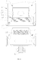
- the atomizer assembly 12 is screwed to the liquid reservoir assembly 11 and is capable of driving the blocker 115 to rotate. During the installation and removal of the atomizer assembly 12, the atomizer assembly 12 drives the blocker 115 to rotate to respectively open and close the liquid outlet 1113.
- the atomizer assembly 12 is formed with a liquid inlet 1233 allowing liquid solution to flow into the atomizer assembly 12.
- the liquid inlet 1233 corresponds to the liquid outlet 1113 such that liquid solution can be injected to the atomizer assembly 12 when the liquid outlet 1113 is opened.
- the rotation of the atomizer assembly 12 can drive the blocker 115 to rotate to close the liquid outlet 1113, which avoids the leakage of liquid solution and thus avoids the waste of liquid solution and the pollution to other components caused by the leakage of liquid solution.
- Upper ends of the inner tube 111 and the outer tube 112 define an annular opening, and the end cover 113 is arranged on the annular opening to cover the annular opening.
- a liquid injecting opening is defined in the end cover 113 through which liquid solution is injected to the liquid reservoir chamber A.
- a through hole communicating with the inner tube 111 is defined in the middle portion of the end cover 113 allowing for flowing of smoke.
- the holder assembly 114 includes an annular top cover 1141 and a hollow holder 1142.
- the top cover 1141 is mounted on the end cover 113 to cover and seal the liquid injecting opening defined in the end cover 113.
- the holder 1142 passes through the top cover 1141 and is inserted into the inner tube 111, allowing air to flow out of the holder 1142.
- the blocker 115 is annular-tube-shaped.
- the blocker 115 is rotatably arranged and is axially installed and positioned.
- the blocker 115 is attached to an inner wall of the inner tube 111.
- An opening 1151 corresponding to the liquid outlet 1113 is defined in the blocker 115.
- the opening 1151 misaligns with the liquid outlet 1113 to close the liquid outlet 1113.
- the opening 115 aligns with the liquid outlet 1113 to communicate the liquid reservoir chamber A with the atomizer assembly 12.
- the blocker 115 can has a rotatable plate structure with a curved surface which closes and opens the liquid outlet 1113 during rotation.
- the liquid reservoir assembly 11 further includes a positioning ring 116.
- the positioning ring 116 includes a third sleeve tube 1161 located between the sleeved portion 1112 and the blocking portion 1153.
- the sleeved portion 1112, the third sleeve tube 1161, and the blocking portion 1153 are sleevedly connected in sequence from outside to inside.
- a protrusion 1162 abutting a lower end of the blocking portion 1153 is formed on an inner ring of the third sleeve tube 1161.
- the third sleeve tube 1161 is riveted to the sleeved portion 1112 to fix the position of the third sleeve tube 1161; the protrusion 1162 is capable of abutting a lower end of the blocker 115 to avoid lateral movement and dropping of the blocker 115.
- an inner wall of the blocking portion 1153 is formed with screw threads allowing for the installation of the atomizer 12.
- the screw threads can be formed on an inner wall of the sleeved tube 1152.
- the protrusion 1162 abuts an outer edge of the corresponding end surface of the blocking portion 11153; and an inclined surface 1154 is defined on an edge of an end surface of the blocking portion 1153 corresponding to the protrusion 1162, for guiding the protrusion 1162 to the inner wall of the blocking portion 1153.
- the inclined surface 1154 is provided with knurling or several circumferentially-spaced groves, which increases the friction between the atomizer assembly 12 and the blocker 115 after the atomizer assembly 12 is tightly rotated to the blocker 115.
- a first friction is generated between the blocker 115 and the inner tube 111 of the liquid reservoir assembly 11, thus, during the installation of the atomizer assembly 12, the atomizer assembly 12 is at first screwed to the blocker 115 and then the atomizer assembly 12 drives the blocker 115 to overcome the first friction to rotate together to open the liquid outlet 1113. This ensures that the liquid outlet 1113 is opened after the atomizer assembly 12 is installed, prevents the liquid outlet 1113 from being opened before the installation of the atomizer assembly 12 is completed, and thus avoids the leakage of liquid solution.
- the first friction can be generated between the blocker 115 and other components of the liquid reservoir assembly 11.
- the blocker 115 can be driven to rotate to open the liquid outlet 1113 when the threaded portion 1211 completely engage with the screw threads formed on the blocker 115.
- the blocker 115 is driven to rotate to close the liquid outlet 1113, the atomizer base 121 is driven to rotate relative to the blocker 115 to separate the screw connection between the threaded portion 1211 and the screw threads of the blocker 115, such that the atomizer assembly can be axially released.
- the blocker 115 can be clamped to the atomizer base 121.
- the restricting mechanism includes an arc slot 1114 formed in the inner tube 111 and a convex stage 1155 arranged on the blocker 115 being inserted into the arc slot 1114. Furthermore, the arc slot 1114 is formed in the bending portion 1111, and the convex stage 1155 is arranged on an end surface of the blocking portion 1153 corresponding to the bending portion 1111.
- the arc slot 1114 can be formed in a side of the bending portion 11111 facing the blocking portion 1153. In some embodiments, the arc slot can be a through slot.
- the number of the liquid outlet 1113 and the opening 1151 are respectively four, and the four liquid outlets 1113 and the four openings 1151 are respectively evenly-spaced in circumferential direction.
- the size of each liquid outlet 1113 corresponds to that of each opening 1151.
- the configuration that the four or more liquid outlets 1113 and the openings 1151 are arranged in the circumferential direction allows the liquid solution to be absorbed more uniformly.
- the maximum rotation degree of the convex stage 1155 in the arc slot 1114 is 45 degrees.
- the opening 1151 exactly aligns with the liquid outlet 1113 to open the liquid outlet 1113; after the blocker 115 is rotated over another 45 degrees, the opening 1151 exactly misaligns with the liquid outlet 1113 to close the liquid outlet 1113.
- the rotation angle of the convex stage 1155 in the arc slot 1114 also can be less than 45 degrees. In some embodiments, the rotation angle of the convex stage 1155 in the arc slot 1114 can accordingly change when the number and arrangement way of the liquid outlets 1113 and the openings 1151 in the circumferential direction change.
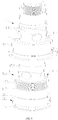
- the atomizer assembly 12 further includes a connection tube 123 mounted on the atomizer base 121, an inner core assembly 124 arranged inside the connection tube 123, a conducible first electrode 125 arranged on the connection tube 123, and a pin 127 arranged on the atomizer base 121.
- the first connection member 1231 includes a first sleeve tube 1236 and an annular first blocking wall 1237.
- the first sleeve tube 1236 is arranged on an outer ring of the first blocking wall 1237.
- the second connection member 1232 includes a second sleeve tube 1234 and an annular second blocking wall 1235.
- the second sleeve tube 1234 is arranged on an outer ring of the second blocking wall 1235.
- One end of the first sleeve tube 1236 is screwed to one end of the second sleeve tube 1234.
- the inner core assembly 124 is columnar-shaped and axially passes through the first connection tube 1236 and the second connection tube 1234.
- the liquid inlet hole 1233 is defined in the first sleeve tube 1236; in other embodiments, the liquid inlet hole 1233 also can be defined in the second sleeve tube 1234 or defined after the first sleeve tube 1236 and the second sleeve tube 1234 are installed together.
- the fixing tube 1243 defines a liquid absorbing hole 1233 corresponding to the liquid inlet hole 1233, such that liquid solution can flow to the liquid absorbing member 1241 through the liquid inlet hole 1233 and the liquid absorbing hole 1244.
- the position and number of the liquid inlet hole 1233 defined in the connection tube 123 and the position and number of the liquid absorbing hole 1244 defined in the fixing tube 1243 are respectively identical to the position and the number of the liquid outlet 1113, which allows the liquid solution to smoothly flow into the atomizer assembly 12.
- the position and number of the liquid inlet hole 1233 and the position and number of the liquid absorbing hole 1244 can be accordingly adjusted, for example, the liquid inlet hole 1233 can circumferentially or axially stagger from the corresponding liquid absorbing hole 1244.
- the fixing tube 1243 is made of metal and has a relatively-high rigidity.
- an elastic annular first sealing gasket 1245 is arranged between the second blocking wall 1235 and the corresponding end portion of the fixing tube 1243
- an elastic annular second sealing gasket 1247 is arranged between the second blocking wall and the corresponding end portion of the fixing tube 1243.
- the first sealing gasket 1245 and the second sealing gasket 1247 are made of flexible material, being capable of interchanging between a compressed state and a rebounding state.
- first sealing gasket 1245 can be arranged between one end of the inner core assembly 124 and the first connection member 1231, and the second sealing gasket 1247 can be arranged between the other end of the inner core assembly and the second connection member 1232, such that the inner core assembly can be rebounded.
- a size of the inner hole of the first sleeve tube 1236 is different from that of the inner hole of the second sleeve tube 1234.
- the first connection member 1231 is located at a lower position
- the second connection member 1232 is located at an upper position
- the inner hole of the second sleeve tube 1234 is smaller than that of the first sleeve tube 1236, thus, after the first connection member 1231 and the second connection member 1232 are installed together, the positioning stage 1246 is formed on inner walls of the first sleeve tube 1236 and the second sleeve tube 1234.
- the second sleeve tube 1234 is secured to the first sleeve tube 1236 by covering on the inner core assembly 124.
- the second electrode 126 is cylindrical and passes through an end side hole of the fixing tube 1243 corresponding to the first blocking wall 1237.
- the second electrode 126 is insulated from the end side hole of the fixing tube 1243.
- an insulation cover is arranged between an outer ring of the second electrode 126 and the end side hole of the fixing tube 1243.
- the second electrode 126 arranged in the end side hole of the fixing tube 1243 is capable of contacting with the first electrode 125 through the resilience of the insulation cover when the fixing tube 1243 is pressed under an axial force after being mounted in the connection tube 123. Even when the axial force applying to the fixing tube 1243 is too large, the abutting force generated between the first electrode 125 and the second electrode 126 are maintained on a suitable level through the resilience of the insulation sleeve. Thus, the first electrode 125 can be kept in good contact with the second electrode 126; further, the abrasion between the first electrode 125 and the second electrode 126 can be reduced. In other embodiments, the second electrode 126 can be omitted to allow the first electrode 125 to be electrically connected to the heater 1242.
- connection tube 123 is made of conducible material, and a lead is sandwiched between the insulation cover and the first blocking wall 1237 to electrically connect the connection tube 123 and the heater 1242.
- the atomizer base 121 is also made of conducible material. One end of the atomizer base 121 is detachably connected to the connection tube 123, and the other end of the atomizer base 121 is connected to a power supply.
- the pin 127 is arranged on the atomizer base 121 at a position corresponding to the first electrode 125. The pin 127 is insulated from the atomizer base 121. After the connection tube 123 is connected to the atomizer base 121, the pin 127 is conducted with the first electrode 125. After the atomizer device 10 is connected to the power supply, the atomizer base 121 and the pin 127 are respectively conducted to the power supply, to supply power to the heater 1242 to vaporize the liquid solution. If the first electrode 125 is long enough, the pin 127 can also be omitted such that the first electrode 125 can be directly conducted with the power supply.
Landscapes
- Nozzles (AREA)
- Disinfection, Sterilisation Or Deodorisation Of Air (AREA)
Claims (13)
- Zerstäuberbaugruppe (12), umfassend eine Verbindungsleitung (123) und eine Innenkernbaugruppe (124), die in der Verbindungsleitung (123) angeordnet ist; wobei die Verbindungsleitung (123) ein Flüssigkeitseinlassloch (1233) definiert, das es flüssiger Lösung ermöglicht, in die Verbindungsleitung (123) zu fließen; wobei die Innenkernbaugruppe (124) eine Heizeinrichtung (1242) zum Erwärmen und Zerstäuben der flüssigen Lösung umfasst, die in die Verbindungsleitung (123) fließt;
wobei die Verbindungsleitung (123) ein erstes Verbindungselement (1231) und ein zweites Verbindungselement (1232) umfasst, das lösbar mit dem ersten Verbindungselement (1231) verbunden ist; und das erste Verbindungselement (1231) und das zweite Verbindungselement (1232) einen Aufnahmeraum definieren, in dem die Innenkernbaugruppe (124) lösbar angeordnet ist; wobei das erste Verbindungselement (1231) eine erste Hülsenleitung (1236) umfasst, das zweite Verbindungselement (1232) eine zweite Hülsenleitung (1234) umfasst; die Innenkernbaugruppe (124) ferner eine leitfähige Fixierungsleitung (1243), die axial durch die Verbindungsleitung (123) verläuft, und ein zylindrisches Flüssigkeitsabsorptionselement (1241) umfasst, das zum Absorbieren von Tabaköl in der Fixierungsleitung (1243) angeordnet ist, wobei die Heizeinrichtung (1242) in dem Flüssigkeitsabsorptionselement (1241) angeordnet und mit der Fixierungsleitung (1243) elektrisch verbunden ist und die Fixierungsleitung (1243) eine Flüssigkeitsabsorptionsloch (1244) definiert, das mit dem Flüssigkeitseinlassloch (1233) übereinstimmt; dadurch gekennzeichnet, dass:
eine Größe eines Innenlochs der ersten Hülsenleitung (1236) sich von derjenigen eines Innenlochs der zweiten Hülsenleitung (1234) unterscheidet, sodass nach dem Zusammenbauen der ersten Hülsenleitung (1236) und der zweiten Hülsenleitung (1234) eine Stufe (1238) an einer Verbindungsposition der ersten Hülsenleitung (1236) und der zweiten Hülsenleitung (1234) an einer Innenwand der Verbindungsleitung (123) gebildet ist, und eine Positionierungsstufe (1246), die an der Stufe (1238) anliegt, an einer Außenwand der Fixierungsleitung (1243) angeordnet ist. - Zerstäuberbaugruppe (12) nach Anspruch 1, wobei ein Ende der ersten Hülsenleitung (1236) mit einem Ende der zweiten Hülsenleitung (1234) verbunden ist; und die Innenkernbaugruppe (124) zylindrisch ist und axial durch die erste Hülsenleitung (1236) und die zweite Hülsenleitung (1234) verläuft.
- Zerstäuberbaugruppe (12) nach Anspruch 2, wobei das erste Verbindungselement (1231) eine ringförmige erste Blockierungswand (1237) umfasst, die an einem Ende der Innenkernbaugruppe (124) anliegt; das zweite Verbindungselement (1232) eine ringförmige zweite Blockierungswand (1235) umfasst, die an dem anderen Ende der Innenkernbaugruppe (124) anliegt; die beiden Enden der Innenkernbaugruppe (124) jeweils in Dichtungseingriff mit der ersten Blockierungswand (1237) und der zweiten Blockierungswand (1235) stehen; ein zentraler Abschnitt der Innenkernbaugruppe (124) ein axiales Durchgangsloch definiert und das Durchgangsloch mit einer Mitte der ersten Blockierungswand (1237) und einer Mitte der zweiten Blockierungswand (1235) in Verbindung steht, damit Rauch dadurch hindurch strömen kann.
- Zerstäuberbaugruppe (12) nach einem der Ansprüche 2 bis 3, wobei eine elastische ringförmige erste Dichtung (1245) zwischen dem ersten Verbindungselement (1231) und dem entsprechenden Ende der Innenkernbaugruppe (124) angeordnet ist, eine elastische ringförmige zweite Dichtung (1247) zwischen dem zweiten Verbindungselement (1232) des entsprechenden Endes der Innenkernbaugruppe (124) angeordnet ist; die erste Dichtung (1245) und die zweite Dichtung (1247) jeweils zwischen einem zusammengedrückten Zustand und einem Rückstellzustand wechseln können; die erste Dichtung (1245) und die zweite Dichtung (1247) nach dem Installieren des ersten Verbindungselements und des zweiten Verbindungselements (1232) zusammengedrückt sind; die erste Dichtung (1245) und die zweite Dichtung (1247) sich nach dem Lösen des ersten Verbindungselements (1231) und des zweiten Verbindungselements (1232) jeweils aus ihrem zusammengedrückten Zustand zurückstellen.
- Zerstäuberbaugruppe (12) nach Anspruch 1, wobei die Zerstäuberbaugruppe (12) ferner eine leitfähige erste Elektrode (125) umfasst; die erste Elektrode (125) einen zylindrischen Körper umfasst und der zylindrische Körper durch ein Innenloch der ersten Blockierungswand verläuft und von der ersten Blockierungswand (1237) isoliert ist; die erste Elektrode (125) elektrisch mit der Heizeinrichtung (1242) verbunden ist; und die Verbindungsleitung (123) aus leitfähigem Material hergestellt ist und elektrisch mit der Fixierungsleitung (1243) verbunden ist.
- Zerstäuberbaugruppe (12) nach Anspruch 5, wobei die Innenkernbaugruppe (124) ferner eine leitfähige zylindrische zweite Elektrode (126) umfasst; die zweite Elektrode (126) durch ein Endseitenloch der Fixierungsleitung (1243) verläuft, das mit der ersten Blockierungswand (1237) übereinstimmt, und eine Isolationsabdeckung zwischen der ersten zweiten Elektrode (126) und dem Endseitenloch der Fixierungsleitung (1243) angeordnet ist; und ein Außenring der zweiten Elektrode (126) elektrisch mit der Heizeinrichtung (1242) verbunden ist, die erste Elektrode (125) und die zweite Elektrode (126) axial aneinander anliegen und miteinander leitend sind und die erste Elektrode (125) durch die zweite Elektrode (126) elektrisch mit der Heizeinrichtung (1242) verbunden ist.
- Zerstäubervorrichtung (10), umfassend die Zerstäuberbaugruppe (12) nach einem der Ansprüche 1 bis 6.
- Zerstäubervorrichtung (10) nach Anspruch 7, wobei die Zerstäuberbaugruppe (12) ferner eine leitfähige Zerstäuberbasis (121) umfasst und die Verbindungsleitung (123) lösbar mit der Zerstäuberbasis (121) verbunden ist; die Zerstäubervorrichtung (10) ferner eine Flüssigkeitsbehälterbaugruppe (11) umfasst; die Zerstäuberbaugruppe (12) lösbar mit der Flüssigkeitsbehälterbaugruppe (11) verbunden ist und die Flüssigkeitsbehälterbaugruppe (11) eine Flüssigkeitsbehälterkammer (A) zum Aufnehmen von flüssiger Lösung bildet, wobei ein Flüssigkeitsauslass (1113) der flüssigen Lösung ermöglicht, aus der Flüssigkeitsbehälterkammer (A) herauszufließen, und ein Blockierstück (115) im Flüssigkeitsauslass (1113) blockiert;
die Zerstäuberbaugruppe (12) auf die Flüssigkeitsbehälterbaugruppe (11) geschraubt ist und das Blockierstück (115) drehend antreiben kann, wodurch das Blockierstück (115) derart drehend angetrieben wird, dass es, während sie installiert wird, den Flüssigkeitsauslass (1113) öffnet, und das Blockierstück (115) derart drehend angetrieben wird, dass es, während sie entfernt wird, den Flüssigkeitsauslass (1113) verschließt; und der Flüssigkeitsauslass (1113) mit dem Flüssigkeitseinlassloch (1233) übereinstimmt, derart, dass flüssige Lösung in die Verbindungsleitung (123) eingespritzt werden kann, wenn der Flüssigkeitsauslass (1113) geöffnet ist. - Zerstäubervorrichtung (10) nach Anspruch 8, wobei das Blockierstück (115) ringförmig-rohrförmig ist und axial positioniert und installiert ist; und das Blockierstück (115) mit einem Gewinde zur Schraubinstallation der Zerstäuberbaugruppe (12) gebildet ist; wobei eine Schrägfläche (1154) an einer Kante einer unteren Endseite des Blockierstücks (115) definiert ist und die Schrägfläche (1154) mit Bördelung oder Nuten gebildet ist, die in Umfangsrichtung beabstandet sind; wobei die Zerstäuberbasis (121) einen Gewindeabschnitt (1211) umfasst, der mit dem Gewinde am Blockierungsabschnitt (1153) in Eingriff steht, ein Außenring des Gewindeabschnitts (1211) mit einem Dichtungsring (122) versehen ist und eine Position des Dichtungsrings (122) mit derjenigen der Schrägfläche (1154) übereinstimmt; wobei eine Öffnung (1151), die mit dem Flüssigkeitsauslass (1113) übereinstimmt, in dem Blockierstück (115) definiert ist; die Öffnung (1151) vor dem Installieren der Zerstäuberbaugruppe (12) nicht am Flüssigkeitsauslass (1113) ausgerichtet ist, um den Flüssigkeitsauslass (1113) zu verschließen; und die Öffnung (1151), nachdem die Zerstäuberbaugruppe (12) installiert wurde, am Flüssigkeitsauslass (1113) ausgerichtet ist, um die Flüssigkeitsbehälterkammer (A) mit der Zerstäuberbaugruppe (12) in Verbindung zu setzen; wobei die Anzahl des Flüssigkeitsauslasses (1113) und der Öffnung (1151) jeweils vier beträgt und die vier Flüssigkeitsauslässe (1113) und die vier Öffnungen (1151) jeweils in Umfangsrichtung beabstandet sind; und eine Größe des Flüssigkeitsauslasses (1113) derjenigen der Öffnung (1151) entspricht und ein maximales Bogenmaß des Flüssigkeitsauslasses (1113) oder ein maximales Bogenmaß der Öffnung (1151) weniger als 45 Grad beträgt.
- Zerstäubervorrichtung (10) nach Anspruch 8, wobei die Flüssigkeitsbehälterbaugruppe (11) eine innere Leitung (111) und eine äußere Leitung (112) umfasst; die Flüssigkeitsbehälterkammer (A) zwischen der inneren Leitung (111) und der äußeren Leitung (112) gebildet ist; und der Flüssigkeitsauslass (1113) in der inneren Leitung (111) gebildet ist und das Blockierstück (115) an einer Innenwand der inneren Leitung (111) angebracht ist; wobei ein unteres Ende der inneren Leitung (111) mit einem Biegungsabschnitt (1111), der sich lateral nach außen erstreckt, und einem gesteckten Abschnitt (1113) gebildet ist, der sich axial von einer Außenkante des Biegungsabschnitts (1111) nach unten erstreckt; das Blockierstück (115) eine Hülsenleitung, auf die eine Innenwand der inneren Leitung (111) gesteckt ist, und einen ringförmigrohrförmigen Blockierungsabschnitt (1153) umfasst, der an einem unteren Ende der Hülsenleitung angeordnet ist; der Blockierungsabschnitt (1153) und die Hülsenleitung koaxial angeordnet sind und ein Außenradius des Blockierungsabschnitts größer als derjenige der Hülsenleitung ist; und ein oberes Ende des Blockierungsabschnitts (1153) am Biegungsabschnitt (1111) anliegt und der gesteckte Abschnitt (1112) auf den Blockierungsabschnitt (1153) aufgesteckt ist; wobei die Flüssigkeitsbehälterbaugruppe (11) ferner einen Positionierungsring (116) umfasst; der Positionierungsring (116) eine dritte Hülsenleitung (1161) zwischen dem gesteckten Abschnitt (1211) und dem Blockierungsabschnitt (1153) umfasst; der aufgesetzte Abschnitt (1211), die dritte Leitung und der Blockierungsabschnitt (1153) von außen nach innen ineinander steckend verbunden sind; und ein Innenring der dritten Hülsenleitung (1161) mit einem Vorsprung (1162) gebildet ist, der an einem unteren Ende des Blockierungsabschnitts (1153) anliegt.
- Zerstäubervorrichtung (10) nach Anspruch 10, ferner umfassend einen Einschränkungsmechanismus zum Einschränken eines Drehbereichs des Blockierstücks (115); wobei der Einschränkungsmechanismus einen Bogenschlitz (1114), der in der inneren Leitung (111) gebildet ist, und eine konvexe Plattform (1162) umfasst, die an dem in den Bogenschlitz (1114) eingeführten Blockierstück (115) angeordnet ist; wobei der Bogenschlitz (1114) im Biegungsabschnitt (1111) gebildet ist und die konvexe Plattform (1162) an einer Endfläche des Blockierungsabschnitts (1153) gebildet ist, die mit dem Biegungsabschnitt (1111) übereinstimmt.
- Zerstäubervorrichtung (10) nach einem der Ansprüche 8 bis 11, wobei eine erste Reibung zwischen dem Blockierstück (115) und der Flüssigkeitsbehälterbaugruppe (11) erzeugt wird, eine zweite Reibung zwischen dem Blockierstück (115) und der Zerstäuberbaugruppe (12) erzeugt wird und die zweite Reibung größer als die erste Reibung ist.
- Elektronische Zigarette, wobei die elektronische Zigarette die Zerstäubervorrichtung (10) nach einem der Ansprüche 7 bis 12 umfasst.
Applications Claiming Priority (1)
| Application Number | Priority Date | Filing Date | Title |
|---|---|---|---|
| PCT/CN2016/087418 WO2018000182A1 (zh) | 2016-06-28 | 2016-06-28 | 电子烟及其雾化装置和雾化组件 |
Publications (3)
| Publication Number | Publication Date |
|---|---|
| EP3287018A1 EP3287018A1 (de) | 2018-02-28 |
| EP3287018A4 EP3287018A4 (de) | 2018-06-13 |
| EP3287018B1 true EP3287018B1 (de) | 2021-12-08 |
Family
ID=60785718
Family Applications (1)
| Application Number | Title | Priority Date | Filing Date |
|---|---|---|---|
| EP16847605.9A Active EP3287018B1 (de) | 2016-06-28 | 2016-06-28 | Elektronische zigarette, zerstäubungsvorrichtung und zerstäubungskomponente davon |
Country Status (3)
| Country | Link |
|---|---|
| US (1) | US10188146B2 (de) |
| EP (1) | EP3287018B1 (de) |
| WO (1) | WO2018000182A1 (de) |
Families Citing this family (34)
| Publication number | Priority date | Publication date | Assignee | Title |
|---|---|---|---|---|
| CN204994622U (zh) * | 2015-09-10 | 2016-01-27 | 深圳市合元科技有限公司 | 雾化器及电子烟 |
| CN105559148B (zh) * | 2016-02-27 | 2018-08-28 | 卓尔悦欧洲控股有限公司 | 雾化器及其电子烟 |
| GB201605102D0 (en) | 2016-03-24 | 2016-05-11 | Nicoventures Holdings Ltd | Mechanical connector for electronic vapour provision system |
| CN106037011B (zh) * | 2016-07-13 | 2019-08-02 | 卓尔悦欧洲控股有限公司 | 雾化头、雾化器及电子烟 |
| CN206603241U (zh) * | 2017-01-20 | 2017-11-03 | 深圳市合元科技有限公司 | 电子烟及雾化器 |
| USD853635S1 (en) * | 2017-02-23 | 2019-07-09 | Shenzhen Smoore Technology Limited | Atomizer for electronic cigarette |
| CN206542922U (zh) * | 2017-03-14 | 2017-10-10 | 常州市派腾电子技术服务有限公司 | 雾化头、雾化器及电子烟 |
| WO2018188231A1 (zh) * | 2017-04-14 | 2018-10-18 | 常州市派腾电子技术服务有限公司 | 加热装置、雾化器及电子烟 |
| USD836243S1 (en) * | 2017-08-15 | 2018-12-18 | Tuanfang Liu | E-cigarette atomizer |
| USD877975S1 (en) * | 2017-10-28 | 2020-03-10 | Vuber Technologies, Inc. | Atomizer |
| USD848673S1 (en) * | 2017-10-31 | 2019-05-14 | Avail Vapor Llc | Microvaporizer cartridge |
| GB201720849D0 (en) * | 2017-12-14 | 2018-01-31 | Nicoventures Holdings Ltd | Vapour provision systems |
| USD867657S1 (en) * | 2017-12-15 | 2019-11-19 | Avanzato Technology Corp. | Dual chamber tank |
| USD861978S1 (en) * | 2018-01-02 | 2019-10-01 | Shenzhen Smoore Technology Limited | Electronic cigarette atomizer |
| CN108578852A (zh) * | 2018-04-03 | 2018-09-28 | 宁波圣宇瑞医疗器械有限公司 | 雾化器 |
| US12096792B2 (en) | 2018-07-23 | 2024-09-24 | Shenzhen First Union Technology Co., Ltd. | Detachable aerosol-generating article |
| USD920572S1 (en) * | 2018-10-22 | 2021-05-25 | Tuanfang Liu | Electronic cigarette |
| USD923867S1 (en) * | 2018-10-24 | 2021-06-29 | Shenzhen Smoore Technology Limited | Atomizer for an electronic cigarette |
| USD857290S1 (en) * | 2018-10-24 | 2019-08-20 | Vuber Technologies, Inc. | Glass core atomizer |
| CN109303355A (zh) | 2018-11-02 | 2019-02-05 | 深圳市合元科技有限公司 | 可拆雾化芯的雾化器及电子烟 |
| GB201903228D0 (en) * | 2019-03-11 | 2019-04-24 | Nicoventures Trading Ltd | Aerosol generation device heater element manufacture |
| EP3939449A4 (de) * | 2019-03-13 | 2023-03-01 | Changzhou Patent Electronic Technology Co., Ltd | Kartusche, batterievorrichtung und elektronische zigarette |
| US11839238B2 (en) | 2019-05-15 | 2023-12-12 | Vaporous Technologies, Inc. | Personal vaporizer and method for filling same |
| US11344066B2 (en) | 2019-05-15 | 2022-05-31 | Vaporous Technologies, Inc. | Personal vaporizer and method for filling same |
| CN110338465B (zh) * | 2019-07-16 | 2024-10-15 | 深圳麦克韦尔科技有限公司 | 换气阀及电子雾化装置 |
| CN115413243B (zh) | 2019-12-23 | 2024-08-27 | Pax实验室公司 | 蒸发器料盒 |
| US11330841B2 (en) | 2020-01-16 | 2022-05-17 | Vaporous Technologies, Inc. | Personal vaporizer for use with vial |
| US11925208B2 (en) * | 2020-06-25 | 2024-03-12 | Altria Client Services Llc | Non-nicotine e-vaping device |
| US11490660B2 (en) | 2020-06-25 | 2022-11-08 | Altria Client Services Llc | Nicotine e-vaping device |
| EP3970534B1 (de) * | 2020-09-17 | 2025-07-02 | Shenzhen Eigate Technology Co., Ltd. | Zerstäuber |
| WO2022070190A1 (en) * | 2020-09-30 | 2022-04-07 | Omega Life Science Ltd. | Electronic cigarettes and cartridges |
| USD1028336S1 (en) | 2021-06-22 | 2024-05-21 | Pax Labs, Inc. | Vaporizer cartridge |
| KR200497167Y1 (ko) * | 2021-10-08 | 2023-08-14 | 이병준 | 전자담배 |
| US11533950B1 (en) | 2022-02-09 | 2022-12-27 | Clear IP Corporation | Atomizer cartridge with integrally formed internal fluid reservoir and mouthpiece portion |
Citations (1)
| Publication number | Priority date | Publication date | Assignee | Title |
|---|---|---|---|---|
| WO2017166263A1 (zh) * | 2016-04-01 | 2017-10-05 | 深圳麦克韦尔股份有限公司 | 电子烟及其雾化装置 |
Family Cites Families (15)
| Publication number | Priority date | Publication date | Assignee | Title |
|---|---|---|---|---|
| DE202012005406U1 (de) * | 2012-05-31 | 2012-06-25 | Thomas Brückmann | Zigarettenartiger, elektrisch betriebener Inhalator mit einem Mundstück, Verdampfer- und Tankraum |
| CN103960781A (zh) * | 2013-09-29 | 2014-08-06 | 深圳市麦克韦尔科技有限公司 | 电子烟 |
| CN203435687U (zh) * | 2013-08-31 | 2014-02-19 | 卓尔悦(常州)电子科技有限公司 | 一种雾化头 |
| CN104126873A (zh) * | 2014-07-07 | 2014-11-05 | 深圳市合元科技有限公司 | 用于电子烟的雾化头、雾化器及电子烟 |
| US10397981B2 (en) * | 2014-12-29 | 2019-08-27 | Shenzhen Kimsen Technology Co., Ltd | Atomizing component and electronic cigarette |
| CN204796750U (zh) * | 2015-06-19 | 2015-11-25 | 卓尔悦(常州)电子科技有限公司 | 雾化器及其气溶胶发生装置 |
| CN205082671U (zh) * | 2015-06-19 | 2016-03-16 | 卓尔悦(常州)电子科技有限公司 | 雾化器及其气溶胶发生装置 |
| CN204949520U (zh) * | 2015-08-14 | 2016-01-13 | 深圳威铂利科技有限公司 | 新型电子烟 |
| CN205143486U (zh) * | 2015-09-02 | 2016-04-13 | 深圳市合元科技有限公司 | 雾化头、雾化器及电子烟 |
| CN105212278B (zh) * | 2015-10-28 | 2019-03-22 | 深圳麦克韦尔股份有限公司 | 电子烟雾化器 |
| CN105433443A (zh) * | 2015-12-25 | 2016-03-30 | 深圳市合元科技有限公司 | 雾化器和电子吸烟装置 |
| CN105595436A (zh) * | 2016-03-11 | 2016-05-25 | 深圳葆威道科技有限公司 | 可拆卸陶瓷发热雾化芯 |
| CN205794806U (zh) * | 2016-06-07 | 2016-12-14 | 深圳市新宜康科技有限公司 | 上组装电子烟雾化器 |
| CN105962420B (zh) * | 2016-06-28 | 2020-01-10 | 深圳麦克韦尔科技有限公司 | 电子烟及其雾化装置和雾化组件 |
| CN205848691U (zh) * | 2016-06-28 | 2017-01-04 | 深圳麦克韦尔股份有限公司 | 电子烟及其雾化装置和雾化组件 |
-
2016
- 2016-06-28 EP EP16847605.9A patent/EP3287018B1/de active Active
- 2016-06-28 WO PCT/CN2016/087418 patent/WO2018000182A1/zh not_active Ceased
- 2016-06-28 US US15/314,514 patent/US10188146B2/en active Active
Patent Citations (1)
| Publication number | Priority date | Publication date | Assignee | Title |
|---|---|---|---|---|
| WO2017166263A1 (zh) * | 2016-04-01 | 2017-10-05 | 深圳麦克韦尔股份有限公司 | 电子烟及其雾化装置 |
Also Published As
| Publication number | Publication date |
|---|---|
| US20180049470A1 (en) | 2018-02-22 |
| EP3287018A1 (de) | 2018-02-28 |
| US10188146B2 (en) | 2019-01-29 |
| EP3287018A4 (de) | 2018-06-13 |
| WO2018000182A1 (zh) | 2018-01-04 |
Similar Documents
| Publication | Publication Date | Title |
|---|---|---|
| EP3287018B1 (de) | Elektronische zigarette, zerstäubungsvorrichtung und zerstäubungskomponente davon | |
| US10188147B2 (en) | Atomization assembly and electronic cigarette | |
| CN105962420B (zh) | 电子烟及其雾化装置和雾化组件 | |
| JP6473823B2 (ja) | アトマイザー、電子たばこおよび交換可能な液体貯蔵装置 | |
| CN108289502B (zh) | 电子烟及其雾化组件 | |
| US10492537B2 (en) | Atomizer head, atomizer and electronic cigarette containing the atomizer | |
| US9894937B2 (en) | Atomizer and electronic cigarette having same | |
| CN108294365B (zh) | 电子烟及其雾化装置 | |
| EP3248479B1 (de) | Elektronische zigarette und zerstäubervorrichtung dafür | |
| EP3446578A1 (de) | Batterieanordnung und elektronische zigarette mit der batterieanordnung | |
| CN210782915U (zh) | 电子雾化装置 | |
| CN207054791U (zh) | 雾化器及其电子烟 | |
| CN205337595U (zh) | 电子烟雾化器 | |
| US11259568B2 (en) | Liquid storage assembly, atomizer and electronic cigarette having the same | |
| CN205648912U (zh) | 电子烟及其雾化装置 | |
| EP3549459A1 (de) | Kartusche und zerstäuber dafür sowie elektronische zigarette | |
| WO2017166263A1 (zh) | 电子烟及其雾化装置 | |
| CN104605482A (zh) | 可更换的雾化单元和包括该雾化单元的雾化器及电子烟 | |
| CN108208935A (zh) | 雾化器及其电子烟 | |
| US20190350264A1 (en) | Upper cover assembly, atomizer and electronic cigarette | |
| CN206687176U (zh) | 雾化器及其电子烟 | |
| US11123502B2 (en) | Vaporizer cartridge system | |
| CN205432131U (zh) | 电子烟雾化器 | |
| CN108013509B (zh) | 一种雾化器及其电子烟 | |
| CN205432130U (zh) | 电子烟雾化器 |
Legal Events
| Date | Code | Title | Description |
|---|---|---|---|
| STAA | Information on the status of an ep patent application or granted ep patent |
Free format text: STATUS: UNKNOWN |
|
| STAA | Information on the status of an ep patent application or granted ep patent |
Free format text: STATUS: THE INTERNATIONAL PUBLICATION HAS BEEN MADE |
|
| PUAI | Public reference made under article 153(3) epc to a published international application that has entered the european phase |
Free format text: ORIGINAL CODE: 0009012 |
|
| STAA | Information on the status of an ep patent application or granted ep patent |
Free format text: STATUS: REQUEST FOR EXAMINATION WAS MADE |
|
| 17P | Request for examination filed |
Effective date: 20170329 |
|
| AK | Designated contracting states |
Kind code of ref document: A1 Designated state(s): AL AT BE BG CH CY CZ DE DK EE ES FI FR GB GR HR HU IE IS IT LI LT LU LV MC MK MT NL NO PL PT RO RS SE SI SK SM TR |
|
| AX | Request for extension of the european patent |
Extension state: BA ME |
|
| A4 | Supplementary search report drawn up and despatched |
Effective date: 20180514 |
|
| RIC1 | Information provided on ipc code assigned before grant |
Ipc: A24F 47/00 20060101AFI20180508BHEP |
|
| DAV | Request for validation of the european patent (deleted) | ||
| DAX | Request for extension of the european patent (deleted) | ||
| STAA | Information on the status of an ep patent application or granted ep patent |
Free format text: STATUS: EXAMINATION IS IN PROGRESS |
|
| 17Q | First examination report despatched |
Effective date: 20210208 |
|
| REG | Reference to a national code |
Ref country code: DE Ref legal event code: R079 Ref document number: 602016067216 Country of ref document: DE Free format text: PREVIOUS MAIN CLASS: A24F0047000000 Ipc: A24F0040420000 |
|
| GRAP | Despatch of communication of intention to grant a patent |
Free format text: ORIGINAL CODE: EPIDOSNIGR1 |
|
| STAA | Information on the status of an ep patent application or granted ep patent |
Free format text: STATUS: GRANT OF PATENT IS INTENDED |
|
| RIC1 | Information provided on ipc code assigned before grant |
Ipc: A24F 40/10 20200101ALN20210806BHEP Ipc: A24F 40/485 20200101ALI20210806BHEP Ipc: A24F 40/42 20200101AFI20210806BHEP |
|
| INTG | Intention to grant announced |
Effective date: 20210827 |
|
| GRAS | Grant fee paid |
Free format text: ORIGINAL CODE: EPIDOSNIGR3 |
|
| GRAA | (expected) grant |
Free format text: ORIGINAL CODE: 0009210 |
|
| STAA | Information on the status of an ep patent application or granted ep patent |
Free format text: STATUS: THE PATENT HAS BEEN GRANTED |
|
| AK | Designated contracting states |
Kind code of ref document: B1 Designated state(s): AL AT BE BG CH CY CZ DE DK EE ES FI FR GB GR HR HU IE IS IT LI LT LU LV MC MK MT NL NO PL PT RO RS SE SI SK SM TR |
|
| REG | Reference to a national code |
Ref country code: GB Ref legal event code: FG4D |
|
| REG | Reference to a national code |
Ref country code: AT Ref legal event code: REF Ref document number: 1453057 Country of ref document: AT Kind code of ref document: T Effective date: 20211215 Ref country code: CH Ref legal event code: EP |
|
| REG | Reference to a national code |
Ref country code: DE Ref legal event code: R096 Ref document number: 602016067216 Country of ref document: DE |
|
| REG | Reference to a national code |
Ref country code: IE Ref legal event code: FG4D |
|
| REG | Reference to a national code |
Ref country code: LT Ref legal event code: MG9D |
|
| REG | Reference to a national code |
Ref country code: NL Ref legal event code: MP Effective date: 20211208 |
|
| PG25 | Lapsed in a contracting state [announced via postgrant information from national office to epo] |
Ref country code: RS Free format text: LAPSE BECAUSE OF FAILURE TO SUBMIT A TRANSLATION OF THE DESCRIPTION OR TO PAY THE FEE WITHIN THE PRESCRIBED TIME-LIMIT Effective date: 20211208 Ref country code: LT Free format text: LAPSE BECAUSE OF FAILURE TO SUBMIT A TRANSLATION OF THE DESCRIPTION OR TO PAY THE FEE WITHIN THE PRESCRIBED TIME-LIMIT Effective date: 20211208 Ref country code: FI Free format text: LAPSE BECAUSE OF FAILURE TO SUBMIT A TRANSLATION OF THE DESCRIPTION OR TO PAY THE FEE WITHIN THE PRESCRIBED TIME-LIMIT Effective date: 20211208 Ref country code: BG Free format text: LAPSE BECAUSE OF FAILURE TO SUBMIT A TRANSLATION OF THE DESCRIPTION OR TO PAY THE FEE WITHIN THE PRESCRIBED TIME-LIMIT Effective date: 20220308 |
|
| REG | Reference to a national code |
Ref country code: AT Ref legal event code: MK05 Ref document number: 1453057 Country of ref document: AT Kind code of ref document: T Effective date: 20211208 |
|
| PG25 | Lapsed in a contracting state [announced via postgrant information from national office to epo] |
Ref country code: SE Free format text: LAPSE BECAUSE OF FAILURE TO SUBMIT A TRANSLATION OF THE DESCRIPTION OR TO PAY THE FEE WITHIN THE PRESCRIBED TIME-LIMIT Effective date: 20211208 Ref country code: NO Free format text: LAPSE BECAUSE OF FAILURE TO SUBMIT A TRANSLATION OF THE DESCRIPTION OR TO PAY THE FEE WITHIN THE PRESCRIBED TIME-LIMIT Effective date: 20220308 Ref country code: LV Free format text: LAPSE BECAUSE OF FAILURE TO SUBMIT A TRANSLATION OF THE DESCRIPTION OR TO PAY THE FEE WITHIN THE PRESCRIBED TIME-LIMIT Effective date: 20211208 Ref country code: HR Free format text: LAPSE BECAUSE OF FAILURE TO SUBMIT A TRANSLATION OF THE DESCRIPTION OR TO PAY THE FEE WITHIN THE PRESCRIBED TIME-LIMIT Effective date: 20211208 Ref country code: GR Free format text: LAPSE BECAUSE OF FAILURE TO SUBMIT A TRANSLATION OF THE DESCRIPTION OR TO PAY THE FEE WITHIN THE PRESCRIBED TIME-LIMIT Effective date: 20220309 Ref country code: ES Free format text: LAPSE BECAUSE OF FAILURE TO SUBMIT A TRANSLATION OF THE DESCRIPTION OR TO PAY THE FEE WITHIN THE PRESCRIBED TIME-LIMIT Effective date: 20211208 |
|
| PG25 | Lapsed in a contracting state [announced via postgrant information from national office to epo] |
Ref country code: NL Free format text: LAPSE BECAUSE OF FAILURE TO SUBMIT A TRANSLATION OF THE DESCRIPTION OR TO PAY THE FEE WITHIN THE PRESCRIBED TIME-LIMIT Effective date: 20211208 |
|
| PG25 | Lapsed in a contracting state [announced via postgrant information from national office to epo] |
Ref country code: SM Free format text: LAPSE BECAUSE OF FAILURE TO SUBMIT A TRANSLATION OF THE DESCRIPTION OR TO PAY THE FEE WITHIN THE PRESCRIBED TIME-LIMIT Effective date: 20211208 Ref country code: SK Free format text: LAPSE BECAUSE OF FAILURE TO SUBMIT A TRANSLATION OF THE DESCRIPTION OR TO PAY THE FEE WITHIN THE PRESCRIBED TIME-LIMIT Effective date: 20211208 Ref country code: RO Free format text: LAPSE BECAUSE OF FAILURE TO SUBMIT A TRANSLATION OF THE DESCRIPTION OR TO PAY THE FEE WITHIN THE PRESCRIBED TIME-LIMIT Effective date: 20211208 Ref country code: PT Free format text: LAPSE BECAUSE OF FAILURE TO SUBMIT A TRANSLATION OF THE DESCRIPTION OR TO PAY THE FEE WITHIN THE PRESCRIBED TIME-LIMIT Effective date: 20220408 Ref country code: EE Free format text: LAPSE BECAUSE OF FAILURE TO SUBMIT A TRANSLATION OF THE DESCRIPTION OR TO PAY THE FEE WITHIN THE PRESCRIBED TIME-LIMIT Effective date: 20211208 Ref country code: CZ Free format text: LAPSE BECAUSE OF FAILURE TO SUBMIT A TRANSLATION OF THE DESCRIPTION OR TO PAY THE FEE WITHIN THE PRESCRIBED TIME-LIMIT Effective date: 20211208 |
|
| PG25 | Lapsed in a contracting state [announced via postgrant information from national office to epo] |
Ref country code: PL Free format text: LAPSE BECAUSE OF FAILURE TO SUBMIT A TRANSLATION OF THE DESCRIPTION OR TO PAY THE FEE WITHIN THE PRESCRIBED TIME-LIMIT Effective date: 20211208 Ref country code: AT Free format text: LAPSE BECAUSE OF FAILURE TO SUBMIT A TRANSLATION OF THE DESCRIPTION OR TO PAY THE FEE WITHIN THE PRESCRIBED TIME-LIMIT Effective date: 20211208 |
|
| REG | Reference to a national code |
Ref country code: DE Ref legal event code: R097 Ref document number: 602016067216 Country of ref document: DE |
|
| PG25 | Lapsed in a contracting state [announced via postgrant information from national office to epo] |
Ref country code: IS Free format text: LAPSE BECAUSE OF FAILURE TO SUBMIT A TRANSLATION OF THE DESCRIPTION OR TO PAY THE FEE WITHIN THE PRESCRIBED TIME-LIMIT Effective date: 20220408 |
|
| PLBE | No opposition filed within time limit |
Free format text: ORIGINAL CODE: 0009261 |
|
| STAA | Information on the status of an ep patent application or granted ep patent |
Free format text: STATUS: NO OPPOSITION FILED WITHIN TIME LIMIT |
|
| PG25 | Lapsed in a contracting state [announced via postgrant information from national office to epo] |
Ref country code: DK Free format text: LAPSE BECAUSE OF FAILURE TO SUBMIT A TRANSLATION OF THE DESCRIPTION OR TO PAY THE FEE WITHIN THE PRESCRIBED TIME-LIMIT Effective date: 20211208 Ref country code: AL Free format text: LAPSE BECAUSE OF FAILURE TO SUBMIT A TRANSLATION OF THE DESCRIPTION OR TO PAY THE FEE WITHIN THE PRESCRIBED TIME-LIMIT Effective date: 20211208 |
|
| 26N | No opposition filed |
Effective date: 20220909 |
|
| PG25 | Lapsed in a contracting state [announced via postgrant information from national office to epo] |
Ref country code: SI Free format text: LAPSE BECAUSE OF FAILURE TO SUBMIT A TRANSLATION OF THE DESCRIPTION OR TO PAY THE FEE WITHIN THE PRESCRIBED TIME-LIMIT Effective date: 20211208 |
|
| PG25 | Lapsed in a contracting state [announced via postgrant information from national office to epo] |
Ref country code: MC Free format text: LAPSE BECAUSE OF FAILURE TO SUBMIT A TRANSLATION OF THE DESCRIPTION OR TO PAY THE FEE WITHIN THE PRESCRIBED TIME-LIMIT Effective date: 20211208 |
|
| REG | Reference to a national code |
Ref country code: CH Ref legal event code: PL |
|
| REG | Reference to a national code |
Ref country code: BE Ref legal event code: MM Effective date: 20220630 |
|
| PG25 | Lapsed in a contracting state [announced via postgrant information from national office to epo] |
Ref country code: LU Free format text: LAPSE BECAUSE OF NON-PAYMENT OF DUE FEES Effective date: 20220628 Ref country code: LI Free format text: LAPSE BECAUSE OF NON-PAYMENT OF DUE FEES Effective date: 20220630 Ref country code: IE Free format text: LAPSE BECAUSE OF NON-PAYMENT OF DUE FEES Effective date: 20220628 Ref country code: FR Free format text: LAPSE BECAUSE OF NON-PAYMENT OF DUE FEES Effective date: 20220630 Ref country code: CH Free format text: LAPSE BECAUSE OF NON-PAYMENT OF DUE FEES Effective date: 20220630 |
|
| PG25 | Lapsed in a contracting state [announced via postgrant information from national office to epo] |
Ref country code: IT Free format text: LAPSE BECAUSE OF FAILURE TO SUBMIT A TRANSLATION OF THE DESCRIPTION OR TO PAY THE FEE WITHIN THE PRESCRIBED TIME-LIMIT Effective date: 20211208 Ref country code: BE Free format text: LAPSE BECAUSE OF NON-PAYMENT OF DUE FEES Effective date: 20220630 |
|
| P01 | Opt-out of the competence of the unified patent court (upc) registered |
Effective date: 20230428 |
|
| PG25 | Lapsed in a contracting state [announced via postgrant information from national office to epo] |
Ref country code: HU Free format text: LAPSE BECAUSE OF FAILURE TO SUBMIT A TRANSLATION OF THE DESCRIPTION OR TO PAY THE FEE WITHIN THE PRESCRIBED TIME-LIMIT; INVALID AB INITIO Effective date: 20160628 |
|
| PG25 | Lapsed in a contracting state [announced via postgrant information from national office to epo] |
Ref country code: MK Free format text: LAPSE BECAUSE OF FAILURE TO SUBMIT A TRANSLATION OF THE DESCRIPTION OR TO PAY THE FEE WITHIN THE PRESCRIBED TIME-LIMIT Effective date: 20211208 Ref country code: CY Free format text: LAPSE BECAUSE OF FAILURE TO SUBMIT A TRANSLATION OF THE DESCRIPTION OR TO PAY THE FEE WITHIN THE PRESCRIBED TIME-LIMIT Effective date: 20211208 |
|
| PG25 | Lapsed in a contracting state [announced via postgrant information from national office to epo] |
Ref country code: MT Free format text: LAPSE BECAUSE OF FAILURE TO SUBMIT A TRANSLATION OF THE DESCRIPTION OR TO PAY THE FEE WITHIN THE PRESCRIBED TIME-LIMIT Effective date: 20211208 |
|
| PGFP | Annual fee paid to national office [announced via postgrant information from national office to epo] |
Ref country code: DE Payment date: 20250617 Year of fee payment: 10 |
|
| PGFP | Annual fee paid to national office [announced via postgrant information from national office to epo] |
Ref country code: GB Payment date: 20250625 Year of fee payment: 10 |
|
| PG25 | Lapsed in a contracting state [announced via postgrant information from national office to epo] |
Ref country code: TR Free format text: LAPSE BECAUSE OF FAILURE TO SUBMIT A TRANSLATION OF THE DESCRIPTION OR TO PAY THE FEE WITHIN THE PRESCRIBED TIME-LIMIT Effective date: 20211208 |