EP3287063B1 - Appareil électrique, système d'appareil électrique doté d'un écran et procédé de fabrication d'un tel dispositif - Google Patents
Appareil électrique, système d'appareil électrique doté d'un écran et procédé de fabrication d'un tel dispositif Download PDFInfo
- Publication number
- EP3287063B1 EP3287063B1 EP17187496.9A EP17187496A EP3287063B1 EP 3287063 B1 EP3287063 B1 EP 3287063B1 EP 17187496 A EP17187496 A EP 17187496A EP 3287063 B1 EP3287063 B1 EP 3287063B1
- Authority
- EP
- European Patent Office
- Prior art keywords
- panel
- display device
- door
- lamination
- front side
- Prior art date
- Legal status (The legal status is an assumption and is not a legal conclusion. Google has not performed a legal analysis and makes no representation as to the accuracy of the status listed.)
- Active
Links
Images
Classifications
-
- A—HUMAN NECESSITIES
- A47—FURNITURE; DOMESTIC ARTICLES OR APPLIANCES; COFFEE MILLS; SPICE MILLS; SUCTION CLEANERS IN GENERAL
- A47L—DOMESTIC WASHING OR CLEANING; SUCTION CLEANERS IN GENERAL
- A47L15/00—Washing or rinsing machines for crockery or tableware
- A47L15/42—Details
- A47L15/4293—Arrangements for programme selection, e.g. control panels; Indication of the selected programme, programme progress or other parameters of the programme, e.g. by using display panels
-
- F—MECHANICAL ENGINEERING; LIGHTING; HEATING; WEAPONS; BLASTING
- F25—REFRIGERATION OR COOLING; COMBINED HEATING AND REFRIGERATION SYSTEMS; HEAT PUMP SYSTEMS; MANUFACTURE OR STORAGE OF ICE; LIQUEFACTION SOLIDIFICATION OF GASES
- F25D—REFRIGERATORS; COLD ROOMS; ICE-BOXES; COOLING OR FREEZING APPARATUS NOT OTHERWISE PROVIDED FOR
- F25D23/00—General constructional features
- F25D23/02—Doors; Covers
- F25D23/028—Details
-
- F—MECHANICAL ENGINEERING; LIGHTING; HEATING; WEAPONS; BLASTING
- F25—REFRIGERATION OR COOLING; COMBINED HEATING AND REFRIGERATION SYSTEMS; HEAT PUMP SYSTEMS; MANUFACTURE OR STORAGE OF ICE; LIQUEFACTION SOLIDIFICATION OF GASES
- F25D—REFRIGERATORS; COLD ROOMS; ICE-BOXES; COOLING OR FREEZING APPARATUS NOT OTHERWISE PROVIDED FOR
- F25D27/00—Lighting arrangements
- F25D27/005—Lighting arrangements combined with control means
-
- F—MECHANICAL ENGINEERING; LIGHTING; HEATING; WEAPONS; BLASTING
- F25—REFRIGERATION OR COOLING; COMBINED HEATING AND REFRIGERATION SYSTEMS; HEAT PUMP SYSTEMS; MANUFACTURE OR STORAGE OF ICE; LIQUEFACTION SOLIDIFICATION OF GASES
- F25D—REFRIGERATORS; COLD ROOMS; ICE-BOXES; COOLING OR FREEZING APPARATUS NOT OTHERWISE PROVIDED FOR
- F25D29/00—Arrangement or mounting of control or safety devices
- F25D29/003—Arrangement or mounting of control or safety devices for movable devices
-
- G—PHYSICS
- G09—EDUCATION; CRYPTOGRAPHY; DISPLAY; ADVERTISING; SEALS
- G09F—DISPLAYING; ADVERTISING; SIGNS; LABELS OR NAME-PLATES; SEALS
- G09F23/00—Advertising on or in specific articles, e.g. ashtrays, letter-boxes
- G09F23/0058—Advertising on or in specific articles, e.g. ashtrays, letter-boxes on electrical household appliances, e.g. on a dishwasher, a washing machine or a refrigerator
-
- A—HUMAN NECESSITIES
- A47—FURNITURE; DOMESTIC ARTICLES OR APPLIANCES; COFFEE MILLS; SPICE MILLS; SUCTION CLEANERS IN GENERAL
- A47L—DOMESTIC WASHING OR CLEANING; SUCTION CLEANERS IN GENERAL
- A47L15/00—Washing or rinsing machines for crockery or tableware
- A47L15/42—Details
- A47L15/4251—Details of the casing
- A47L15/4257—Details of the loading door
- A47L15/4265—Arrangements of door covering/decoration panels or plinths, e.g. for integrated dishwashers
-
- F—MECHANICAL ENGINEERING; LIGHTING; HEATING; WEAPONS; BLASTING
- F25—REFRIGERATION OR COOLING; COMBINED HEATING AND REFRIGERATION SYSTEMS; HEAT PUMP SYSTEMS; MANUFACTURE OR STORAGE OF ICE; LIQUEFACTION SOLIDIFICATION OF GASES
- F25D—REFRIGERATORS; COLD ROOMS; ICE-BOXES; COOLING OR FREEZING APPARATUS NOT OTHERWISE PROVIDED FOR
- F25D2327/00—Lighting arrangements not provided for in other groups of this subclass
- F25D2327/001—Lighting arrangements on the external side of the refrigerator, freezer or cooling box
-
- F—MECHANICAL ENGINEERING; LIGHTING; HEATING; WEAPONS; BLASTING
- F25—REFRIGERATION OR COOLING; COMBINED HEATING AND REFRIGERATION SYSTEMS; HEAT PUMP SYSTEMS; MANUFACTURE OR STORAGE OF ICE; LIQUEFACTION SOLIDIFICATION OF GASES
- F25D—REFRIGERATORS; COLD ROOMS; ICE-BOXES; COOLING OR FREEZING APPARATUS NOT OTHERWISE PROVIDED FOR
- F25D2400/00—General features of, or devices for refrigerators, cold rooms, ice-boxes, or for cooling or freezing apparatus not covered by any other subclass
- F25D2400/18—Aesthetic features
-
- F—MECHANICAL ENGINEERING; LIGHTING; HEATING; WEAPONS; BLASTING
- F25—REFRIGERATION OR COOLING; COMBINED HEATING AND REFRIGERATION SYSTEMS; HEAT PUMP SYSTEMS; MANUFACTURE OR STORAGE OF ICE; LIQUEFACTION SOLIDIFICATION OF GASES
- F25D—REFRIGERATORS; COLD ROOMS; ICE-BOXES; COOLING OR FREEZING APPARATUS NOT OTHERWISE PROVIDED FOR
- F25D2400/00—General features of, or devices for refrigerators, cold rooms, ice-boxes, or for cooling or freezing apparatus not covered by any other subclass
- F25D2400/36—Visual displays
Definitions
- the invention relates to an arrangement of an electrical device with a panel, in particular a dishwasher or a refrigerator, which in a kitchen is provided with a panel to be attached over a surface to a door of the electrical device.
- the invention also relates to a method for producing such an arrangement.
- Such electrical appliances are also known as built-in or fully integrated household appliances. They do not have their own front or front cladding that should be visible when installed. Rather, a panel is mounted on the front of the door, and this panel can be held in a design that otherwise forms the fronts in the kitchen.
- a panel is usually a board made of wood or a fiber board with a coating, for example a lacquer or a real wood veneer.
- a household appliance is known as an electrical appliance with a concealed control panel which has a display device in an opening on the panel in front of a door of the electrical appliance. This is obviously always visible.
- the invention is based on the object of providing an arrangement of an electrical device with a panel and a method for producing such an arrangement, with which problems of the prior art can be solved and in particular it is possible to provide a display or an illuminated display for a To provide such an electrical device with a panel attached in front of it in a practical and cost-effective manner.
- the electrical appliance which is advantageously a dishwasher or a refrigerator and which is to be installed in a kitchen, has a door that can be opened, with a flat or large panel being applied to this door, as can be done with integrated electrical appliances.
- This door can advantageously be completely covered by the panel.
- the door can particularly advantageously be hingedly openable, but alternatively it can also be intended for a so-called pull-out refrigerator.
- a display device which has or forms an illuminated display, is arranged on the door.
- the structure of this display device is explained in more detail below, but it can be arranged at the front of the door of the electrical device, in the door or even behind the door. Advantageous it is arranged at least partially or a part of it on the front or outward facing front of the door. A part of the display device protrudes beyond the front or front surface of the door, in particular an optical part of the display device or possibly provided light guide bodies or light guides, as will be explained in more detail below.
- the protrusion of the display device or at least a part of the display device has the meaning that it can reach into a recess to be made in the panel for the production of said arrangement or to be made thereon in order to be closer to its front surface or to be closer to it the facing covering or covering the front surface. It is advantageously on the back of the lamination.
- this covering is designed to be translucent in such a way that the illuminated display in an activated state, that is, when it is lit, shines through the covering and is thus recognizable to an operator. The closer the display device is to this lamination or a rear side of the lamination, the better, brighter and sharper the illuminated display can be perceived.
- an electrical device designed as a fully integrated electrical device it is possible for an electrical device designed as a fully integrated electrical device to be provided, as is customary, with a said panel for installation in a kitchen.
- simply arranging a display device in any arbitrary manner in this diaphragm results in a visual impression that is usually not particularly advantageous, which is precisely to be avoided by the provision of such a diaphragm.
- the electrical device is not in operation, nothing should be visible, in particular no deactivated or inactive display device, which usually does not look very appealing.
- the prior art mentioned at the beginning avoids this by projecting downwards onto the floor area, with nothing being visible in the non-active state either, neither an illuminated display nor a display device.
- the illuminated display can occupy a single closed area on the door. This means that the illuminated display is not provided at a number of separate or distant locations, so that only a single recess has to be made in the said panel. In addition, a spatially combined illuminated display is visually more appealing, and the manufacturing outlay for the display device is also significantly reduced.
- the display device or the illuminated display can have a plurality of luminous elements that can be illuminated independently of one another. These can, for example, form at least two seven-segment displays and have LEDs for this purpose. Their arrangement or the construction of an illuminated display can take place in accordance with the prior art, as is also shown, for example, in FIG DE 10352714 A is known. Such seven-segment displays can display numerical values as well as simple letters or symbols. The light elements can also form or illuminate and represent any other symbols.
- Electronics for the display device in particular on a printed circuit board or a component carrier, can be attached to or in front of the door of the electrical device. It is protected and covered at the front by the panel to be attached. A connection to this electronics can or the like by means of cables, foil conductors. take place through the door, since the operating device and the control are often also located in the door in such electrical devices, in particular dishwashers.
- electronics can also be arranged behind or in the door and only one type of separate display module of the illuminated display with luminous elements and the aforementioned light guide bodies or light guides can be arranged on or at the front of the door, in particular protruding from the door. This means that in A smaller recess can be provided for the panel, since there is no space for all of the electronics in it, but only for the aforementioned display module or lighting elements and light guide body or light guide.
- the display device has at least one aforementioned light-permeable light guide body or light guide for the illuminated display.
- a light guide body or light guide is preferably arranged between the aforementioned lighting elements and a front surface of the screen.
- a similar material can therefore be used. This also serves to ensure that the aforementioned luminous elements do not themselves have to be arranged as close as possible to the lamination in order to be easily recognizable through it or to form a clearly recognizable luminous display.
- an aforementioned light guide body or light guide can have a covering masking.
- a mask can be a type of lacquer or printing.
- At least one cutout is provided per light guide body or light guide, which forms a type of translucent symbol.
- a symbol can also be displayed in a certain form as an illuminated display in a very simply designed light guide body or light guide.
- the display device can have a cover or a cover plate. This can form the front of the display device.
- a cover or cover plate should be at least partially translucent. It serves as a closure of the display device, in particular as a mechanically stable closure and possibly also to achieve a stable and surface-flush closure in the aforementioned recess in the panel.
- Such a cover or cover plate can advantageously consist of glass or completely translucent plastic. Possibly it can also at least partially have the aforementioned properties of light guide body or light guide, that is to say made of translucent or opaque material exist and ensure that the indicator light is evened out. It can possibly also have an aforementioned masking on the front and / or rear to represent a symbol that can be transilluminated.
- An aforementioned cover or cover plate can advantageously be designed in a very simple geometric basic shape in order to facilitate the production of a recess in the panel and the fitting.
- a rectangular shape or, even better, a circular shape is ideal here.
- a precisely defined and exact recess can be produced very easily with a circular hole saw.
- an aforementioned display device with electronics or its component carrier or, if this is arranged elsewhere, at least one cable connection, the lighting elements, possibly a light guide body or light guide and possibly a cover or cover plate is designed as an independently manageable unit. This can then easily be attached to the door of the electrical device or attached when the electrical device is installed. Especially when the display device can be moved in connection with a cable, flexible conductor or the like. an exact adaptation to a recess produced in the diaphragm can thus be achieved in order to be able to compensate for errors or tolerances that arise in the process.
- Such mobility of the display device relative to the door or a front side of the door can advantageously be at least in a direction perpendicular to the front side of the door, advantageously generally. In this way, it is easy to adapt to different thicknesses of a panel to be attached.
- the cables, flexible conductors or the like. can compensate for this by dimensioning the length accordingly.
- the electronics are arranged behind the front surface of the door of the electrical device or in the door, but also the lighting elements themselves.
- the display device to be arranged on the door can then advantageously be formed by light guides, as it were, which exit from said unit and run into the door and emerge at the front of the door. They can then be connected to the aforementioned further light guide bodies or light guides, which in turn turn the luminosity of the light guides, so to speak, into an illuminated display that shows symbols.
- An arrangement according to the invention has an electrical device as described above and a cover for it, the cover being attached to the door of the electrical device. In this case, it largely covers the door, advantageously at an upper edge and on the sides, particularly advantageously at least essentially downwards as well.
- a recess is provided in the panel or is made therein during manufacture of the arrangement in order to arrange the display device therein or at least the areas that protrude beyond the front of the door.
- Such a recess can be continuous, advantageously with a constant cross section, in particular in order to be able to produce it more easily, as has been described above, for example with a circular hole saw.
- a front side of the display device is advantageously in direct contact with a rear side of the lamination. In this way, fluoroscopy is easily possible when the illuminated display is activated, while only the lamination with its optics can be seen when the illuminated display is deactivated.
- This lamination covers the panel at least in the area of the display device, so that it is not visible, in particular also not in its function as a display device.
- a lamination as the above-described film or a film-like lamination can have a thickness less than or equal to 1 mm, advantageously 0.01 mm to 0.5 mm thick.
- the transparency of the lamination should be such that it can be illuminated by the illuminated display or the light of the illuminated elements of the display device and the illuminated display can thus be recognized.
- the smallest possible distance between the front side of the display device or light exit from the display device and the lamination itself or its rear side must be observed.
- Said lamination can on the one hand have a plastic carrier film on which a decorative layer is applied, which forms the front or front surface.
- a decorative layer can be a colored layer or a thin metallization, as is known from the field of film technology. If such a metallization is thin enough, it can also be well illuminated by a luminous display which, for example, has a conventional SMD LED with medium luminosity as a luminous element.
- the display device can have at least one touch switch or a proximity switch for operating functions of the electrical device on a front side or at the front. It is therefore possible to create a type of operating device with an operating element and an illuminated display. This is particularly advantageous with a touch switch or proximity switch Capacitive sensor element, but also optical touch switches or proximity switches are possible with shining through the covering, which is actually translucent. Other functional principles of touch switches or proximity switches are also conceivable.
- the touch switch or proximity switch is arranged close to the illuminated display or within the illuminated display, that is to say within its luminous appearance.
- the display device, the touch switch (s) or proximity switch and the capacitive sensor elements provided for this can preferably be designed as a structural unit. This means that assembly and, above all, electrical connection are easy to carry out.
- the aforementioned component carriers or printed circuit boards for the illuminated display or its electronics can also carry the touch switch or proximity switch with the sensor elements.
- the display device and touch switch can particularly advantageously be integrated or designed as a structural unit according to the prior art, see, for example, FIG DE 10352714 A1 for an optical touch switch or the EP 1030536 A2 or the WO 2011/012501 A1 for a capacitive touch switch.
- optical or capacitive sensor elements simultaneously serve as touch switches and also as proximity switches with respect to the front side or the surface of the lamination. So you can first recognize an approach of a finger and that a touch with the finger and distinguish them from each other. It is thus possible that when the finger approaches the lamination in the area of the display device or operating device, for example to less than 10 cm or 5 cm, the illuminated display is first activated in the function of a proximity switch. In this way, the possible functions as an operating device can be displayed to an operator by the illuminated display. Concrete operation can then take place in the function of a touch switch. For the exact realization, the DE 102007057076 A1 referenced.
- a touch switch or capacitive sensor elements should advantageously rest on the rear side of the lamination for good functioning or reliable detection of an operation or touch or approach. In this way, a flush design of the front of the door is achieved or maintained.
- the sensor element can either surround a luminous element, as in the DE 10352714 A1 or the EP 1030536 A2 demonstrate.
- a sensor element can be transparent, as is the case with the WO 2011/012501 A1 shows, and extend over a large area above or above the lighting elements. Electrical contact can be made to capacitive sensor elements on top of a display device or a light guide body, as described there, advantageously via laterally extending contacts.
- a recess must be made in the panel for mounting the electrical device in the kitchen, which recess is at least large enough to accommodate the display device. In particular, it must be able to accommodate the part of the display device standing over the front of the door.
- the panel is then attached to the door, with this projecting part being adjusted in the recess depending on the type of connection between the protruding part of the display device and the electrical device or its door.
- a lamination fastened or arranged on the front side of the panel then ultimately covers the display device.
- the covering can be attached to the panel before the panel is attached to the door of the electrical device. Then the application of the lining may be simplified, but the arrangement of the panel on the door is somewhat more difficult. Furthermore, during this assembly process, care must be taken not to damage or adversely affect the lamination.
- the lining can be attached to the panel after the panel has already been attached to the door. This is a bit more complex. But then the last assembly step is attaching the lamination and it can be better protected against damage. Furthermore, the arrangement of the display device in the recess and a possible adjustment or precise setting are simpler.
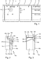
- a kitchen 1 is shown with a simplified front view of a kitchen work front, which is designed as usual.
- a base cabinet 4 and, to the right of it, drawers 5 are arranged under a worktop 2.
- an inventive arrangement 10 of a dishwasher 11 is provided as a household appliance, which is designed and arranged as a fully integrated household appliance.
- the sectional view of the Fig. 2 serves in connection with the prior art documents explained at the beginning to better understand the arrangement 10 of the dishwasher 11.
- the dishwasher 11 has a door 13 which is hinged on a lower edge in an articulated manner, as is customary for such fully integrated dishwashers.
- An operating device with operating elements in the form of pushbuttons or touch sensors is arranged on an upper edge of the door 13 (not shown here). An essential part of the control of the dishwasher 11 is therefore contained in the door 13.
- the front or front surface of the dishwasher 11 in FIG Fig. 1 is formed by a film 40 as a lamination according to the invention, which covers the entire front of the door 13.
- a handle 16 of the dishwasher which can be seen here, is placed at the front on this film 40 and fastened, for example screwed.
- a luminous display 18 can be seen in the upper area, which here is a type of seven-segment display Fig. 2 to be seen display device is formed. It represents the number “87”, which can be easily recognized as an illuminated display 18. This number shows an operator the remaining running time of a currently running program of the operation of the dishwasher 11. In principle, however, very different symbols or information can be displayed.
- the illuminated display 18 and also the film 40 are designed in such a way that nothing can be seen in the deactivated state of the illuminated display 18, that is to say when it is switched off. An operator then only perceives the front side of the film 40 or the film 40 itself. At the same time, the film 40, at least in the area of the illuminated display 18, is so translucent, usually due to a correspondingly small thickness, that when the illuminated display 18 is activated, it is possible to shine through the film 40. The illuminated display 18 can then be clearly seen.
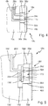
- the structure of the embodiment of Fig. 2 shows the door 13a in section, a recess 14a being provided in the door 13a to the right towards the front of the dishwasher 11 or towards the arrangement 10a.
- This can be a few millimeters deep and have a diameter or width and height of a few centimeters, for example 3 cm to 10 cm.
- a channel 15 leads from the recess 14a to a control of the dishwasher 11 arranged in the door 13a.
- a supply line 20a runs therein as an electrical supply and control to a component carrier 19a, which is completely embedded in the recess 14a.
- the component carrier 19a is part of a display device 17a and can possibly have further components on one of its upper sides. These can serve to control one of the LEDs 22a on its front side pointing to the right.
- These LEDs 22a are advantageously SMD LEDs, whereby they should be designed to be relatively bright with a light output of at least 0.01 Im, advantageously at least 0.1 Im.
- any number of LEDs 22a can be arranged in any desired manner be provided. At least two seven-segment displays are advantageous accordingly Fig. 1 can be displayed, possibly also another, in order to be able to display a symbol or a letter in addition to a two-digit number.
- a light guide body 24a is placed on the component carrier 19 or via the LED 22a, which is advantageously designed in one piece and in the form of a block. It can serve to equalize the luminous display of the LED 22a for a uniform and beautiful-looking luminous display 18a. Furthermore, it can serve as a protection and front cover for the display device 17a. For this purpose, it can be inserted precisely into a recess 32a in a panel 30a.
- a panel 30a corresponds to a conventional panel such as is used for a fully integrated dishwasher 11 in an arrangement 10 according to the invention.
- Such a panel 30a is advantageously made of wood or plywood or fiber material such as pressboard or MDF.
- the recess 32a is made to fit the light guide body 24a or the display device 17a therein, usually by a kitchen fitter or fitter of the kitchen. It is also installed in a position that exactly matches the dishwasher 11.
- a film 40a is applied as a lamination, in particular glued on as a self-adhesive film.
- This film 40a covers, as it does the Fig. 1 shows the entire door 13 of the dishwasher. Only a recessed lower bar is usually not covered, as is known from such fully integrated kitchen appliances.
- the film 40a is generally advantageously made of plastic or has a plastic base as a type of carrier. It can have a colored coating on its front side or it can be colored through. It can also represent an imitation wood veneer, possibly even with a light structure, as is known for such imitation wood veneer foils. It can also have a thin metallization. In any case, however, it should be transparent to light in such a way that the light from an aforementioned LED 22a can be seen through it. This film 40a will then be applied by the same fitter for the kitchen.
- the display device 17a in particular with the component carrier 19a, is firmly attached, for example glued, in the recess 14a of the door 13a.
- the light guide body 24a protrudes over a front surface of the door 13a, but disappears, so to speak, in the recess 32a of the panel 30a.
- the display device 17a is mounted on the door 13a by the manufacturer or in the factory of the manufacturer of the dishwasher 11a.
- a symbol shape or a defined luminous shape of the illuminated display 18a can be formed by corresponding channels in the light guide body 24a, which are not shown here but are known from the seven-segment displays mentioned at the outset.
- an additional masking or printing with corresponding cutouts can also be provided on a front side of the light guide body 24a.
- the film 40a should therefore also be glued onto the front side of the light guide body 24a. In addition to the aforementioned technical reasons for better fluoroscopy, this is also important for a visual appearance that is as appealing as possible. Furthermore, the light guide body 24a should be arranged as precisely as possible in the recess 32a so that no joints can be seen through the film 40a or no such joint or recess is visible when the front of the dishwasher 11 is stressed, for example during cleaning. Finally, the film 40a as a lamination is intended to create the impression that there is a stable, continuous and uniform or monolithic front side.
- FIG. 3 In an arrangement 10b according to the invention, only one continuous channel 15b is provided in a door 13b of a differently designed dishwasher 11b.
- a component carrier 19b is arranged on the rear of the door 13b, that is to say on the inside. It can be covered towards the interior of the dishwasher 11b and, in particular, be connected to a control of the dishwasher (not shown here). It is easy to imagine that the component carrier 19b is also completely omitted here and that its functionality of controlling the LED 22b of the display device 17b or for the illuminated display 18b is taken over by components or a processor of the general control of the dishwasher.
- a supply line 20b to the LEDs 22b runs in the channel 15b in the door 13b, so that these are designed as a type of integrated structural unit together with the light guide body 24b and an electrical connection not shown in detail.
- This light guide body 24b or this Unit is in turn arranged in a recess 32b of a panel 30b, which accordingly Fig. 2 can be formed.
- This arrangement should therefore again be designed to fit precisely and flush with the surface.
- a film 40b is applied from the front as a lamination according to the invention, which covers the entire front side of the panel 30b and thus also the door 13b and forms the optical surface. The same applies to the formation of this film 40b as stated above.
- An illuminated display 18b can be seen when the LED 22b is activated. If the LEDs 22b are inactive, nothing can be seen except the front side of the film 40b.
- FIG Fig. 4 Another alternative embodiment of an arrangement 10c according to the invention is shown in FIG Fig. 4 shown.
- a relatively large channel 15c is provided in a door 13c of a dishwasher according to the invention. It leads up to a control of the dishwasher, not shown, and contains two light guides 26c or actually significantly more, namely one light guide 26c for each illuminated segment of the illuminated display 18c.
- the light guides 26c lead with slightly widened ends into a light guide body 24c, which consists of a plastic as described above. It also belongs to the display device 17c and is accordingly inserted tightly flush and firmly in a recess 32c of a panel 30c. On the front could now according to the representations of Figs.
- a corresponding film can be glued on directly as a lamination.
- a full-area disk 35c made of material that is transparent to light at least in the area of the illuminated display 18c is provided.
- This disk 35c covers the entire front of the door 13c or the panel 30c. So it is also attached by a kitchen fitter, possibly even cut to size.
- a plastic for example acrylic, is therefore a suitable material for the disk 35c. Its thickness can be relatively small, for example 1 mm to 5 mm.
- the task of this disk 35c is to provide additional protection for the display device 17c.
- an exactly full-area and uninterrupted flat front side is to be provided, which can then be provided or glued with the film 40c as a lamination.
- Such a large or full-area disk 35c can, however, be provided regardless of whether LED as in the Figs. 2 and 3 are provided at the front of the display device or a few millimeters below the film 40 or whether, as here in FIG Fig. 4 the case, light guides are provided.
- the light guides 26c can have a certain amount of freedom of movement for the light guide body 24c, so that it can be easily inserted into a recess 32c in the panel 30c and certain assembly tolerances can be compensated for. A joint running in between would not be so bad in the present case, since the full-surface pane 35c is still mounted in front of it.
- an electrical supply line 20d is provided in a channel 15d of the door 13d.
- a display device 17d according to the invention is arranged in a recess 14d on the front side of the door 13d.
- a component carrier 19d of the display device 17d is not inserted firmly or flush into the recess 14d, but has a distance therefrom.
- the component carrier 19d is held in that it forms a structural unit with the light guide body 24d or is glued to it or is otherwise mechanically connected to it.
- the light guide body 24d is connected with its front side to a disk 35d and at the rear side thereof, so that a structural unit is formed overall.
- This disk 35d is fixed in a recess 32d in the panel 30d, for example glued. This takes place without a joint and flush with the surface of the panel 30d, so that a film 40d can once again be glued on as a lamination very easily.
- a capacitive sensor element 28d is also attached here on the front side of the light guide body 24d, as has been explained above as an advantageous possibility.
- the capacitive sensor element 28d is advantageously arranged over a large area or particularly advantageously over the entire area on the front side of the light guide body 24d, preferably in accordance with the aforementioned WO 2011/012501 A1 as a coating.
- a large sensor element is thus provided. It is electrically contacted and connected to the component carrier 19d by an electrically conductive connection guided along the side of the light guide body 24d, for example also by a side coating, in particular also to a control and evaluation, as is known from the cited prior art and here is easy to implement. For this reason, a more detailed representation can be dispensed with.
- the lamination 40d By placing a finger on the lamination 40d in front of the capacitive sensor element 28d, operation takes place through this and through the disk 35d in the usual way.
- the lamination should therefore be designed in such a way that this is possible.
- the position of the capacitive sensor element 28d or a touch switch formed thereby can be conveyed by the illuminated display.
- the above-described function of a proximity switch can also be implemented in this way, namely it can recognize whether a finger is approaching less than 10 cm or 5 cm, for example.
- the illuminated display 18d which was previously completely or partially deactivated, can first be activated via a corresponding control.
- the capacitive sensor element 28d turns the display device 17d into an operating device with an illuminated display and at least one operating element for an operator, that is to say with input and output.
- a dishwasher could as an electrical device by placing the finger on a flashing light display 18d, which indicates the end of a washing process, can be switched off without having to open the door 13.
- a disk 35d is also provided for the display device 17d, which, however, corresponds to the light guide body 24 in the embodiments of FIG Figs. 2 and 3 is let into the panel 30 flush with the surface.
- the disk 35d can be quite thick and mechanically stable. Furthermore, it has the advantage that by forming a structural unit together with the light guide body 24d and the component carrier 19d, a certain flexibility in the arrangement or placement is possible, since no fastening is provided directly in the door 13d and the aforementioned recess 14d also allows sufficient leeway.
- Fig. 5 it can also be seen that the usual LEDs 22d are again provided on a front side of the component carrier 19d, but also other electrical components, for example for controlling this LED 22d and / or the capacitive sensor element 28d. Sufficient space is provided here due to the somewhat larger recess 14d.
- a disk 35d can also consist of plastic, for example acrylic glass, and have a thickness of 2 mm to 5 mm or even more. It is stable enough not to be depressed in the area of the display device 17d.
Landscapes
- Engineering & Computer Science (AREA)
- Physics & Mathematics (AREA)
- Chemical & Material Sciences (AREA)
- Combustion & Propulsion (AREA)
- Mechanical Engineering (AREA)
- Thermal Sciences (AREA)
- General Engineering & Computer Science (AREA)
- General Physics & Mathematics (AREA)
- Theoretical Computer Science (AREA)
- Illuminated Signs And Luminous Advertising (AREA)
- Cold Air Circulating Systems And Constructional Details In Refrigerators (AREA)
- Push-Button Switches (AREA)
Claims (14)
- Dispositif (10) comprenant un appareil électrique (11) et un écran (30) pour l'appareil électrique pour l'installation dans une cuisine (1), dans lequel- l'appareil électrique présente une face avant,- l'appareil électrique présente, sur la face avant, une porte (13) essentiellement en pleine surface à ouvrir,- un écran (30) peut être attaché à plat sur la porte (13),- un dispositif d'affichage (17) est disposé sur la porte (13),- le dispositif d'affichage (17) présente un affichage illuminé (18),- au moins une partie du dispositif d'affichage (17) dépasse au-delà de la face avant de la porte (13),- l'écran est fixé à la porte (13) de l'appareil électrique et recouvre ladite porte en grande partie,
caractérisé en ce que- un renfoncement (32) est agencé dans l'écran pour l'arrangement du dispositif d'affichage (17) là-dedans,- l'écran (30) est recouvert d'un laminage (40) au moins dans la région du dispositif d'affichage,- le laminage est transparent à la lumière dans la région du dispositif d'affichage (17) de telle manière que l'affichage illuminé (18) dans un état actif transparaît à travers le laminage (40) et est perceptible et dans un état inactif de l'affichage illuminé (18) seulement le laminage (40) et son aspect visuel est apparent. - Dispositif selon la revendication 1, caractérisé en ce que l'affichage illuminé (18) prend une seule région fermée sur la porte (13).
- Dispositif selon la revendication 1 ou 2, caractérisé en ce que l'affichage illuminé (18) présente sur le dispositif d'affichage (17) une pluralité d'éléments lumineux (22) capables d'être illuminés indépendamment l'un de l'autre, en particulier avec au moins deux affichages à sept-segments.
- Dispositif selon l'une des revendications précédentes, caractérisé en ce que le dispositif d'affichage (17) présente au moins un corps conducteur de lumière (24) ou conduit de lumière (26) transparent à la lumière pour l'affichage illuminé (18), arrangés de préférence entre les éléments lumineux (22) selon la revendication 3 et une surface de la face avant de l'écran (30), dans lequel en particulier le ou les corps conducteur de lumière (24) ou conduit(s) de lumière (26) présentent un masquage recouvrant avec au moins un découpage per corps conducteur de lumière (24) ou conduit de lumière (26) sous forme de symbole translucide.
- Dispositif selon l'une des revendications précédentes, caractérisé en ce que le dispositif d'affichage (17) présente un couvercle ou panneau de recouvrement (35) formant sa face avant, de préférence un couvercle ou panneau de recouvrement au moins partiellement transparent à la lumière, dans lequel en particulier le couvercle ou panneau de recouvrement (35) présentent un masquage recouvrant avec au moins un découpage sous forme de symbole translucide.
- Dispositif selon l'une des revendications précédentes, caractérisé en ce que le dispositif d'affichage (17) est arrangé sur la porte de manière à être déplaçable par rapport à la face avant de la porte (13), en particulier vers une direction perpendiculaire à la face avant de la porte (13), dans lequel de préférence le dispositif d'affichage (17) est raccordé à une commande de l'appareil électrique (11) par le biais de fils ou conducteurs (20) flexibles ou d'autres choses semblables.
- Dispositif selon l'une des revendications précédentes, caractérisé en ce que le dispositif d'affichage (17) sur une face avant présente un interrupteur tactile ou un interrupteur de proximité, en particulier un interrupteur tactile avec un élément capteur capacitif (28), dans lequel l'interrupteur tactile est disposé proche à ou au sein de l'affichage illuminé (18), dans lequel de préférence le dispositif d'affichage (17) et l'interrupteur tactile ou l'élément capteur capacitif (28) sont sous forme d'une unité physique.
- Dispositif selon l'une des revendications précédentes, caractérisé en ce que le laminage (40) est mince ou un type de feuille présentant une épaisseur inférieure ou égale à 1 mm, dans lequel de préférence le laminage est une feuille, en particulier une feuille autoadhésive (40).
- Dispositif selon l'une des revendications précédentes, caractérisé en ce que le laminage (40) présente une feuille porteuse synthétique avec une couche décorative appliquée en tant que face avant, dans lequel en particulier la couche décorative est une couche colorée ou une métallisation.
- Dispositif selon l'une des revendications précédentes, caractérisé en ce que le dispositif d'affichage (17), en particulier avec un couvercle ou panneau de recouvrement (35) selon la revendication 5, prend appui sur la face arrière du laminage (40) ou est à fleur avec la face avant de l'écran (30).
- Dispositif selon l'une des revendications précédentes, caractérisé en ce que l'interrupteur tactile ou l'interrupteur de proximité selon la revendication 7 est disposé derrière le laminage (40), en particulier l'élément capteur capacitif (28) est disposé derrière le laminage (40), dans lequel de préférence la région du laminage devant l'interrupteur tactile ou l'interrupteur de proximité forme une région tactile pour l'interrupteur tactile.
- Procédé de fabrication d'un dispositif (10) selon l'une des revendications précédentes, caractérisé par les étapes :- produire un renfoncement (32) dans l'écran (30), le renfoncement étant au moins assez grand pour accueillir le dispositif d'affichage (17) de l'appareil électrique (11),- ensuite fixer l'écran (30) sur la porte (13), dans lequel le laminage (40) est fixé sur la face avant de l'écran (30) et ce faisant le dispositif d'affichage (17) est recouvert.
- Procédé selon la revendication 12, caractérisé en ce que le laminage (40) est attaché à l'écran (30) avant que l'écran soit attaché à la porte (13).
- Procédé selon la revendication 12, caractérisé en ce que le laminage (40) est attaché à l'écran (30) après que l'écran avait été fixé sur la porte (13), dans lequel de préférence après rattachement de l'écran à la porte et avant application du laminage (40) sur l'écran (30) le dispositif d'affichage (17) est disposé ou ajusté dans le renfoncement de l'écran de telle manière qu'une face avant du dispositif d'affichage (17) est à fleur avec la face avant de l'écran (30).
Priority Applications (1)
| Application Number | Priority Date | Filing Date | Title |
|---|---|---|---|
| PL17187496T PL3287063T3 (pl) | 2016-08-25 | 2017-08-23 | Urządzenie elektryczne, układ takiego urządzenia elektrycznego z panelem i sposób wytwarzania takiego układu |
Applications Claiming Priority (1)
| Application Number | Priority Date | Filing Date | Title |
|---|---|---|---|
| DE102016216035.4A DE102016216035A1 (de) | 2016-08-25 | 2016-08-25 | Elektrogerät, Anordnung eines solchen Elektrogeräts mit einer Blende und Verfahren zur Herstellung einer solchen Anordnung |
Publications (2)
| Publication Number | Publication Date |
|---|---|
| EP3287063A1 EP3287063A1 (fr) | 2018-02-28 |
| EP3287063B1 true EP3287063B1 (fr) | 2021-03-17 |
Family
ID=59702560
Family Applications (1)
| Application Number | Title | Priority Date | Filing Date |
|---|---|---|---|
| EP17187496.9A Active EP3287063B1 (fr) | 2016-08-25 | 2017-08-23 | Appareil électrique, système d'appareil électrique doté d'un écran et procédé de fabrication d'un tel dispositif |
Country Status (4)
| Country | Link |
|---|---|
| EP (1) | EP3287063B1 (fr) |
| CN (1) | CN107773192B (fr) |
| DE (1) | DE102016216035A1 (fr) |
| PL (1) | PL3287063T3 (fr) |
Cited By (1)
| Publication number | Priority date | Publication date | Assignee | Title |
|---|---|---|---|---|
| EP4487751A4 (fr) * | 2022-03-04 | 2025-06-18 | LG Electronics Inc. | Lave-vaisselle |
Families Citing this family (4)
| Publication number | Priority date | Publication date | Assignee | Title |
|---|---|---|---|---|
| US11083360B2 (en) * | 2019-04-26 | 2021-08-10 | Whirlpool Corporation | Appliance with light guide |
| DE102020109814A1 (de) | 2020-02-18 | 2021-08-19 | Liebherr-Hausgeräte Ochsenhausen GmbH | Einbaukühlgerät mit Türöffnungsmechanismus |
| US11266291B1 (en) | 2020-12-08 | 2022-03-08 | Haier Us Appliance Solutions, Inc. | Dishwasher appliance with a sidefire LED lightguide |
| CN116045592B (zh) * | 2022-12-12 | 2024-07-23 | 珠海格力电器股份有限公司 | 冰箱照明系统及其控制方法、冰箱 |
Citations (1)
| Publication number | Priority date | Publication date | Assignee | Title |
|---|---|---|---|---|
| WO2014101930A1 (fr) * | 2012-12-24 | 2014-07-03 | Arcelik Anonim Sirketi | Lave-vaisselle présentant des moyens d'indication visuellement améliorés |
Family Cites Families (19)
| Publication number | Priority date | Publication date | Assignee | Title |
|---|---|---|---|---|
| DE19907226A1 (de) | 1999-02-19 | 2000-08-24 | Ego Elektro Geraetebau Gmbh | Berührungsschalter für ein Elektro-Gerät |
| DE20316158U1 (de) * | 2002-11-25 | 2003-12-24 | Electrolux Home Products Corporation N.V. | Haushaltsgerätetür mit verdeckt angeordneter Bedienblende |
| DE20221965U1 (de) | 2002-11-25 | 2009-12-31 | Electrolux Home Products Corporation N.V. | In einer Möbelreihe integrierbares Haushaltgerät mit einer Anzeigevorrichtung |
| DE10259763B4 (de) | 2002-12-19 | 2017-02-09 | BSH Hausgeräte GmbH | Haushaltgerät, insbesondere Einbau-Haushaltgerät |
| DE10352714A1 (de) | 2003-11-05 | 2005-07-07 | E.G.O. Elektro-Gerätebau GmbH | Bedieneinrichtung |
| DE102007017272A1 (de) * | 2007-04-12 | 2008-10-30 | BSH Bosch und Siemens Hausgeräte GmbH | Vollintegriertes Einbau-Haushaltsgerät |
| DE102007057076B4 (de) | 2007-11-21 | 2012-03-29 | E.G.O. Elektro-Gerätebau GmbH | Kochfeld und Verfahren zum Betrieb eines Kochfeldes |
| DE102009026659B4 (de) * | 2009-06-03 | 2024-08-01 | BSH Hausgeräte GmbH | Haushaltsgerät |
| DE102009036161B4 (de) | 2009-07-28 | 2017-01-12 | E.G.O. Elektro-Gerätebau GmbH | Sensorelementeinrichtung und Verfahren zur Herstellung einer Sensorelementeinrichtung |
| DE102011077896A1 (de) * | 2011-06-21 | 2012-12-27 | BSH Bosch und Siemens Hausgeräte GmbH | Bedien- und Anzeigeeinrichtung für ein Haushaltsgerät und Haushaltsgerät |
| DE102011081822A1 (de) * | 2011-08-30 | 2012-10-04 | BSH Bosch und Siemens Hausgeräte GmbH | Geschirrspülmaschine mit einer tür |
| US20140015814A1 (en) * | 2012-07-11 | 2014-01-16 | General Electric Company | Device and method for adjusting viewing angle of appliance display |
| WO2014167806A1 (fr) * | 2013-04-12 | 2014-10-16 | パナソニック株式会社 | Réfrigérateur |
| US20150090689A1 (en) * | 2013-09-27 | 2015-04-02 | Corning Incorporated | Compositions for protecting display glass and methods of use thereof |
| US20170203479A1 (en) * | 2014-07-09 | 2017-07-20 | Sabic Global Technologies B.V. | In mold decoration of a film laminated substrate |
| CN106573448A (zh) * | 2014-08-20 | 2017-04-19 | 康宁股份有限公司 | 大且薄的玻璃/金属层压件 |
| DE102014221786A1 (de) * | 2014-10-27 | 2016-04-28 | BSH Hausgeräte GmbH | Haushaltsgerät mit einer Eingabevorrichtung, die eine Andrückvorrichtung umfasst |
| WO2016105312A1 (fr) * | 2014-12-26 | 2016-06-30 | Arcelik Anonim Sirketi | Lave-vaisselle encastrable |
| DE102016113162A1 (de) * | 2015-07-28 | 2017-02-02 | Schott Ag | Bedienblende für ein Haushaltsgerät mit zumindest einer Benutzerschnittstelle, Haushaltsgerät und Verfahren zur Herstellung der Bedienblende mit Benutzerschnittstelle |
-
2016
- 2016-08-25 DE DE102016216035.4A patent/DE102016216035A1/de not_active Withdrawn
-
2017
- 2017-08-23 EP EP17187496.9A patent/EP3287063B1/fr active Active
- 2017-08-23 PL PL17187496T patent/PL3287063T3/pl unknown
- 2017-08-25 CN CN201710742161.1A patent/CN107773192B/zh not_active Expired - Fee Related
Patent Citations (1)
| Publication number | Priority date | Publication date | Assignee | Title |
|---|---|---|---|---|
| WO2014101930A1 (fr) * | 2012-12-24 | 2014-07-03 | Arcelik Anonim Sirketi | Lave-vaisselle présentant des moyens d'indication visuellement améliorés |
Cited By (1)
| Publication number | Priority date | Publication date | Assignee | Title |
|---|---|---|---|---|
| EP4487751A4 (fr) * | 2022-03-04 | 2025-06-18 | LG Electronics Inc. | Lave-vaisselle |
Also Published As
| Publication number | Publication date |
|---|---|
| CN107773192A (zh) | 2018-03-09 |
| PL3287063T3 (pl) | 2021-09-20 |
| EP3287063A1 (fr) | 2018-02-28 |
| CN107773192B (zh) | 2021-12-31 |
| DE102016216035A1 (de) | 2018-03-01 |
Similar Documents
| Publication | Publication Date | Title |
|---|---|---|
| EP3287063B1 (fr) | Appareil électrique, système d'appareil électrique doté d'un écran et procédé de fabrication d'un tel dispositif | |
| EP1573111B1 (fr) | Appareil electromenager equipe d'un dispositif de commande et d'un dispositif d'affichage | |
| EP2853027B1 (fr) | Agencement avec dispositif a element capteur sur un support de composants pour un commutateur tactile capacitif d'un dispositif de commande, dispositif de commande et plaque de cuisson avec un tel agencement | |
| DE102006013937A1 (de) | Bedienblendenanordnung für Haushaltsmaschinen und Verfahren zur Herstellung einer Bedienblendenanordnung | |
| EP2723930A1 (fr) | Dispositif de commande et d'affichage d'un appareil ménager et appareil ménager | |
| EP3084961A1 (fr) | Dispositif d'entrée sensible au contact et/ou au rapprochement | |
| DE102004062752A1 (de) | Integriertes Betriebsanzeigeelement | |
| DE102017218243B3 (de) | Verfahren zum Herstellen zumindest eines Teils einer berührungssensitiven Bedieneinrichtung, berührungssensitive Bedieneinrichtung und Kraftfahrzeug | |
| EP1635368B1 (fr) | Unité d'installation électrique/électronique | |
| EP3232428B1 (fr) | Élément d'affichage, afficheur comprenant un tel élément d'affichage et appareil électrique doté d'un tel afficheur | |
| EP3385623B1 (fr) | Plaque de cuisson avec une unité de commande et de signalisation | |
| DE602005003793T2 (de) | Einbaufähige Geschirrspülmaschine | |
| EP1731841B1 (fr) | Plaque de cuisson avec dispositif de commande | |
| DE102005023440A1 (de) | Anzeige- und/oder Bedienungspaneel | |
| DE202008011846U1 (de) | Duschtrennwand mit Bedieneinrichtung und Dusche mit einer solchen Duschtrennwand | |
| EP3145082A1 (fr) | Dispositif de commande d'un appareil electrique, appareil electrique et procede de fabrication d'un tel dispositif de commande | |
| DE202005017536U1 (de) | Tür für Haushaltsgeräte | |
| EP2987427A1 (fr) | Porte d'armoire a glace et armoire a glace dotee d'une telle porte | |
| EP3105510B1 (fr) | Appareil ménager avec un panneau frontal | |
| DE102014100629A1 (de) | Geschirrspülmaschine | |
| DE102016002893A1 (de) | Ein- und/oder Ausgabegerät mit hinterleuchteten Symbolen | |
| DE102004043650B4 (de) | Elektrische/elektronische Installationseinheit | |
| DE102009058201B4 (de) | Flügelanlage mit Beleuchtungssystem | |
| DE202005018658U1 (de) | Elektrische Schaltervorrichtung | |
| EP1555586B1 (fr) | Montre commutateur pour appareils ménagers |
Legal Events
| Date | Code | Title | Description |
|---|---|---|---|
| PUAI | Public reference made under article 153(3) epc to a published international application that has entered the european phase |
Free format text: ORIGINAL CODE: 0009012 |
|
| STAA | Information on the status of an ep patent application or granted ep patent |
Free format text: STATUS: THE APPLICATION HAS BEEN PUBLISHED |
|
| AK | Designated contracting states |
Kind code of ref document: A1 Designated state(s): AL AT BE BG CH CY CZ DE DK EE ES FI FR GB GR HR HU IE IS IT LI LT LU LV MC MK MT NL NO PL PT RO RS SE SI SK SM TR |
|
| AX | Request for extension of the european patent |
Extension state: BA ME |
|
| STAA | Information on the status of an ep patent application or granted ep patent |
Free format text: STATUS: REQUEST FOR EXAMINATION WAS MADE |
|
| 17P | Request for examination filed |
Effective date: 20180828 |
|
| RBV | Designated contracting states (corrected) |
Designated state(s): AL AT BE BG CH CY CZ DE DK EE ES FI FR GB GR HR HU IE IS IT LI LT LU LV MC MK MT NL NO PL PT RO RS SE SI SK SM TR |
|
| GRAP | Despatch of communication of intention to grant a patent |
Free format text: ORIGINAL CODE: EPIDOSNIGR1 |
|
| STAA | Information on the status of an ep patent application or granted ep patent |
Free format text: STATUS: GRANT OF PATENT IS INTENDED |
|
| INTG | Intention to grant announced |
Effective date: 20201015 |
|
| GRAS | Grant fee paid |
Free format text: ORIGINAL CODE: EPIDOSNIGR3 |
|
| GRAA | (expected) grant |
Free format text: ORIGINAL CODE: 0009210 |
|
| STAA | Information on the status of an ep patent application or granted ep patent |
Free format text: STATUS: THE PATENT HAS BEEN GRANTED |
|
| AK | Designated contracting states |
Kind code of ref document: B1 Designated state(s): AL AT BE BG CH CY CZ DE DK EE ES FI FR GB GR HR HU IE IS IT LI LT LU LV MC MK MT NL NO PL PT RO RS SE SI SK SM TR |
|
| RAP1 | Party data changed (applicant data changed or rights of an application transferred) |
Owner name: E.G.O. ELEKTRO-GERAETEBAU GMBH |
|
| REG | Reference to a national code |
Ref country code: GB Ref legal event code: FG4D Free format text: NOT ENGLISH |
|
| REG | Reference to a national code |
Ref country code: CH Ref legal event code: EP |
|
| REG | Reference to a national code |
Ref country code: DE Ref legal event code: R096 Ref document number: 502017009721 Country of ref document: DE |
|
| REG | Reference to a national code |
Ref country code: IE Ref legal event code: FG4D Free format text: LANGUAGE OF EP DOCUMENT: GERMAN |
|
| REG | Reference to a national code |
Ref country code: AT Ref legal event code: REF Ref document number: 1371430 Country of ref document: AT Kind code of ref document: T Effective date: 20210415 |
|
| REG | Reference to a national code |
Ref country code: LT Ref legal event code: MG9D |
|
| PG25 | Lapsed in a contracting state [announced via postgrant information from national office to epo] |
Ref country code: NO Free format text: LAPSE BECAUSE OF FAILURE TO SUBMIT A TRANSLATION OF THE DESCRIPTION OR TO PAY THE FEE WITHIN THE PRESCRIBED TIME-LIMIT Effective date: 20210617 Ref country code: HR Free format text: LAPSE BECAUSE OF FAILURE TO SUBMIT A TRANSLATION OF THE DESCRIPTION OR TO PAY THE FEE WITHIN THE PRESCRIBED TIME-LIMIT Effective date: 20210317 Ref country code: FI Free format text: LAPSE BECAUSE OF FAILURE TO SUBMIT A TRANSLATION OF THE DESCRIPTION OR TO PAY THE FEE WITHIN THE PRESCRIBED TIME-LIMIT Effective date: 20210317 Ref country code: GR Free format text: LAPSE BECAUSE OF FAILURE TO SUBMIT A TRANSLATION OF THE DESCRIPTION OR TO PAY THE FEE WITHIN THE PRESCRIBED TIME-LIMIT Effective date: 20210618 Ref country code: BG Free format text: LAPSE BECAUSE OF FAILURE TO SUBMIT A TRANSLATION OF THE DESCRIPTION OR TO PAY THE FEE WITHIN THE PRESCRIBED TIME-LIMIT Effective date: 20210617 |
|
| REG | Reference to a national code |
Ref country code: NL Ref legal event code: MP Effective date: 20210317 |
|
| PG25 | Lapsed in a contracting state [announced via postgrant information from national office to epo] |
Ref country code: SE Free format text: LAPSE BECAUSE OF FAILURE TO SUBMIT A TRANSLATION OF THE DESCRIPTION OR TO PAY THE FEE WITHIN THE PRESCRIBED TIME-LIMIT Effective date: 20210317 Ref country code: RS Free format text: LAPSE BECAUSE OF FAILURE TO SUBMIT A TRANSLATION OF THE DESCRIPTION OR TO PAY THE FEE WITHIN THE PRESCRIBED TIME-LIMIT Effective date: 20210317 Ref country code: LV Free format text: LAPSE BECAUSE OF FAILURE TO SUBMIT A TRANSLATION OF THE DESCRIPTION OR TO PAY THE FEE WITHIN THE PRESCRIBED TIME-LIMIT Effective date: 20210317 |
|
| PG25 | Lapsed in a contracting state [announced via postgrant information from national office to epo] |
Ref country code: NL Free format text: LAPSE BECAUSE OF FAILURE TO SUBMIT A TRANSLATION OF THE DESCRIPTION OR TO PAY THE FEE WITHIN THE PRESCRIBED TIME-LIMIT Effective date: 20210317 |
|
| PG25 | Lapsed in a contracting state [announced via postgrant information from national office to epo] |
Ref country code: EE Free format text: LAPSE BECAUSE OF FAILURE TO SUBMIT A TRANSLATION OF THE DESCRIPTION OR TO PAY THE FEE WITHIN THE PRESCRIBED TIME-LIMIT Effective date: 20210317 Ref country code: CZ Free format text: LAPSE BECAUSE OF FAILURE TO SUBMIT A TRANSLATION OF THE DESCRIPTION OR TO PAY THE FEE WITHIN THE PRESCRIBED TIME-LIMIT Effective date: 20210317 Ref country code: LT Free format text: LAPSE BECAUSE OF FAILURE TO SUBMIT A TRANSLATION OF THE DESCRIPTION OR TO PAY THE FEE WITHIN THE PRESCRIBED TIME-LIMIT Effective date: 20210317 Ref country code: SM Free format text: LAPSE BECAUSE OF FAILURE TO SUBMIT A TRANSLATION OF THE DESCRIPTION OR TO PAY THE FEE WITHIN THE PRESCRIBED TIME-LIMIT Effective date: 20210317 |
|
| PG25 | Lapsed in a contracting state [announced via postgrant information from national office to epo] |
Ref country code: PT Free format text: LAPSE BECAUSE OF FAILURE TO SUBMIT A TRANSLATION OF THE DESCRIPTION OR TO PAY THE FEE WITHIN THE PRESCRIBED TIME-LIMIT Effective date: 20210719 Ref country code: RO Free format text: LAPSE BECAUSE OF FAILURE TO SUBMIT A TRANSLATION OF THE DESCRIPTION OR TO PAY THE FEE WITHIN THE PRESCRIBED TIME-LIMIT Effective date: 20210317 Ref country code: SK Free format text: LAPSE BECAUSE OF FAILURE TO SUBMIT A TRANSLATION OF THE DESCRIPTION OR TO PAY THE FEE WITHIN THE PRESCRIBED TIME-LIMIT Effective date: 20210317 Ref country code: IS Free format text: LAPSE BECAUSE OF FAILURE TO SUBMIT A TRANSLATION OF THE DESCRIPTION OR TO PAY THE FEE WITHIN THE PRESCRIBED TIME-LIMIT Effective date: 20210717 |
|
| REG | Reference to a national code |
Ref country code: DE Ref legal event code: R097 Ref document number: 502017009721 Country of ref document: DE |
|
| PLBE | No opposition filed within time limit |
Free format text: ORIGINAL CODE: 0009261 |
|
| STAA | Information on the status of an ep patent application or granted ep patent |
Free format text: STATUS: NO OPPOSITION FILED WITHIN TIME LIMIT |
|
| PG25 | Lapsed in a contracting state [announced via postgrant information from national office to epo] |
Ref country code: DK Free format text: LAPSE BECAUSE OF FAILURE TO SUBMIT A TRANSLATION OF THE DESCRIPTION OR TO PAY THE FEE WITHIN THE PRESCRIBED TIME-LIMIT Effective date: 20210317 Ref country code: AL Free format text: LAPSE BECAUSE OF FAILURE TO SUBMIT A TRANSLATION OF THE DESCRIPTION OR TO PAY THE FEE WITHIN THE PRESCRIBED TIME-LIMIT Effective date: 20210317 Ref country code: ES Free format text: LAPSE BECAUSE OF FAILURE TO SUBMIT A TRANSLATION OF THE DESCRIPTION OR TO PAY THE FEE WITHIN THE PRESCRIBED TIME-LIMIT Effective date: 20210317 |
|
| 26N | No opposition filed |
Effective date: 20211220 |
|
| PG25 | Lapsed in a contracting state [announced via postgrant information from national office to epo] |
Ref country code: SI Free format text: LAPSE BECAUSE OF FAILURE TO SUBMIT A TRANSLATION OF THE DESCRIPTION OR TO PAY THE FEE WITHIN THE PRESCRIBED TIME-LIMIT Effective date: 20210317 |
|
| REG | Reference to a national code |
Ref country code: CH Ref legal event code: PL |
|
| PG25 | Lapsed in a contracting state [announced via postgrant information from national office to epo] |
Ref country code: MC Free format text: LAPSE BECAUSE OF FAILURE TO SUBMIT A TRANSLATION OF THE DESCRIPTION OR TO PAY THE FEE WITHIN THE PRESCRIBED TIME-LIMIT Effective date: 20210317 |
|
| REG | Reference to a national code |
Ref country code: BE Ref legal event code: MM Effective date: 20210831 |
|
| PG25 | Lapsed in a contracting state [announced via postgrant information from national office to epo] |
Ref country code: LI Free format text: LAPSE BECAUSE OF NON-PAYMENT OF DUE FEES Effective date: 20210831 Ref country code: IT Free format text: LAPSE BECAUSE OF FAILURE TO SUBMIT A TRANSLATION OF THE DESCRIPTION OR TO PAY THE FEE WITHIN THE PRESCRIBED TIME-LIMIT Effective date: 20210317 Ref country code: CH Free format text: LAPSE BECAUSE OF NON-PAYMENT OF DUE FEES Effective date: 20210831 |
|
| PG25 | Lapsed in a contracting state [announced via postgrant information from national office to epo] |
Ref country code: IS Free format text: LAPSE BECAUSE OF FAILURE TO SUBMIT A TRANSLATION OF THE DESCRIPTION OR TO PAY THE FEE WITHIN THE PRESCRIBED TIME-LIMIT Effective date: 20210717 Ref country code: LU Free format text: LAPSE BECAUSE OF NON-PAYMENT OF DUE FEES Effective date: 20210823 |
|
| PG25 | Lapsed in a contracting state [announced via postgrant information from national office to epo] |
Ref country code: IE Free format text: LAPSE BECAUSE OF NON-PAYMENT OF DUE FEES Effective date: 20210823 Ref country code: FR Free format text: LAPSE BECAUSE OF NON-PAYMENT OF DUE FEES Effective date: 20210831 Ref country code: BE Free format text: LAPSE BECAUSE OF NON-PAYMENT OF DUE FEES Effective date: 20210831 |
|
| PG25 | Lapsed in a contracting state [announced via postgrant information from national office to epo] |
Ref country code: HU Free format text: LAPSE BECAUSE OF FAILURE TO SUBMIT A TRANSLATION OF THE DESCRIPTION OR TO PAY THE FEE WITHIN THE PRESCRIBED TIME-LIMIT; INVALID AB INITIO Effective date: 20170823 |
|
| PG25 | Lapsed in a contracting state [announced via postgrant information from national office to epo] |
Ref country code: CY Free format text: LAPSE BECAUSE OF FAILURE TO SUBMIT A TRANSLATION OF THE DESCRIPTION OR TO PAY THE FEE WITHIN THE PRESCRIBED TIME-LIMIT Effective date: 20210317 |
|
| REG | Reference to a national code |
Ref country code: AT Ref legal event code: MM01 Ref document number: 1371430 Country of ref document: AT Kind code of ref document: T Effective date: 20220823 |
|
| PG25 | Lapsed in a contracting state [announced via postgrant information from national office to epo] |
Ref country code: AT Free format text: LAPSE BECAUSE OF NON-PAYMENT OF DUE FEES Effective date: 20220823 |
|
| PGFP | Annual fee paid to national office [announced via postgrant information from national office to epo] |
Ref country code: TR Payment date: 20230816 Year of fee payment: 7 Ref country code: GB Payment date: 20230824 Year of fee payment: 7 |
|
| PGFP | Annual fee paid to national office [announced via postgrant information from national office to epo] |
Ref country code: PL Payment date: 20230725 Year of fee payment: 7 Ref country code: DE Payment date: 20230824 Year of fee payment: 7 |
|
| PG25 | Lapsed in a contracting state [announced via postgrant information from national office to epo] |
Ref country code: MK Free format text: LAPSE BECAUSE OF FAILURE TO SUBMIT A TRANSLATION OF THE DESCRIPTION OR TO PAY THE FEE WITHIN THE PRESCRIBED TIME-LIMIT Effective date: 20210317 |
|
| PG25 | Lapsed in a contracting state [announced via postgrant information from national office to epo] |
Ref country code: MT Free format text: LAPSE BECAUSE OF FAILURE TO SUBMIT A TRANSLATION OF THE DESCRIPTION OR TO PAY THE FEE WITHIN THE PRESCRIBED TIME-LIMIT Effective date: 20210317 |
|
| REG | Reference to a national code |
Ref country code: DE Ref legal event code: R119 Ref document number: 502017009721 Country of ref document: DE |
|
| GBPC | Gb: european patent ceased through non-payment of renewal fee |
Effective date: 20240823 |
|
| PG25 | Lapsed in a contracting state [announced via postgrant information from national office to epo] |
Ref country code: DE Free format text: LAPSE BECAUSE OF NON-PAYMENT OF DUE FEES Effective date: 20250301 |
|
| PG25 | Lapsed in a contracting state [announced via postgrant information from national office to epo] |
Ref country code: GB Free format text: LAPSE BECAUSE OF NON-PAYMENT OF DUE FEES Effective date: 20240823 |
|
| PG25 | Lapsed in a contracting state [announced via postgrant information from national office to epo] |
Ref country code: PL Free format text: LAPSE BECAUSE OF NON-PAYMENT OF DUE FEES Effective date: 20240823 |