EP3287076B1 - Röntgenstrahlenvorrichtung mit bewegungssensor und röntgenbildgebungsverfahren damit - Google Patents
Röntgenstrahlenvorrichtung mit bewegungssensor und röntgenbildgebungsverfahren damit Download PDFInfo
- Publication number
- EP3287076B1 EP3287076B1 EP16783395.3A EP16783395A EP3287076B1 EP 3287076 B1 EP3287076 B1 EP 3287076B1 EP 16783395 A EP16783395 A EP 16783395A EP 3287076 B1 EP3287076 B1 EP 3287076B1
- Authority
- EP
- European Patent Office
- Prior art keywords
- ray
- irradiating device
- radiographic
- pointing angle
- radiographic mode
- Prior art date
- Legal status (The legal status is an assumption and is not a legal conclusion. Google has not performed a legal analysis and makes no representation as to the accuracy of the status listed.)
- Active
Links
Images


Classifications
-
- A—HUMAN NECESSITIES
- A61—MEDICAL OR VETERINARY SCIENCE; HYGIENE
- A61B—DIAGNOSIS; SURGERY; IDENTIFICATION
- A61B6/00—Apparatus or devices for radiation diagnosis; Apparatus or devices for radiation diagnosis combined with radiation therapy equipment
- A61B6/54—Control of apparatus or devices for radiation diagnosis
- A61B6/547—Control of apparatus or devices for radiation diagnosis involving tracking of position of the device or parts of the device
-
- A—HUMAN NECESSITIES
- A61—MEDICAL OR VETERINARY SCIENCE; HYGIENE
- A61B—DIAGNOSIS; SURGERY; IDENTIFICATION
- A61B6/00—Apparatus or devices for radiation diagnosis; Apparatus or devices for radiation diagnosis combined with radiation therapy equipment
- A61B6/08—Auxiliary means for directing the radiation beam to a particular spot, e.g. using light beams
-
- A—HUMAN NECESSITIES
- A61—MEDICAL OR VETERINARY SCIENCE; HYGIENE
- A61B—DIAGNOSIS; SURGERY; IDENTIFICATION
- A61B6/00—Apparatus or devices for radiation diagnosis; Apparatus or devices for radiation diagnosis combined with radiation therapy equipment
- A61B6/44—Constructional features of apparatus for radiation diagnosis
- A61B6/4429—Constructional features of apparatus for radiation diagnosis related to the mounting of source units and detector units
- A61B6/4435—Constructional features of apparatus for radiation diagnosis related to the mounting of source units and detector units the source unit and the detector unit being coupled by a rigid structure
-
- A—HUMAN NECESSITIES
- A61—MEDICAL OR VETERINARY SCIENCE; HYGIENE
- A61B—DIAGNOSIS; SURGERY; IDENTIFICATION
- A61B6/00—Apparatus or devices for radiation diagnosis; Apparatus or devices for radiation diagnosis combined with radiation therapy equipment
- A61B6/50—Apparatus or devices for radiation diagnosis; Apparatus or devices for radiation diagnosis combined with radiation therapy equipment specially adapted for specific body parts; specially adapted for specific clinical applications
- A61B6/51—Apparatus or devices for radiation diagnosis; Apparatus or devices for radiation diagnosis combined with radiation therapy equipment specially adapted for specific body parts; specially adapted for specific clinical applications for dentistry
- A61B6/512—Intraoral means
-
- A—HUMAN NECESSITIES
- A61—MEDICAL OR VETERINARY SCIENCE; HYGIENE
- A61B—DIAGNOSIS; SURGERY; IDENTIFICATION
- A61B6/00—Apparatus or devices for radiation diagnosis; Apparatus or devices for radiation diagnosis combined with radiation therapy equipment
- A61B6/54—Control of apparatus or devices for radiation diagnosis
- A61B6/542—Control of apparatus or devices for radiation diagnosis involving control of exposure
-
- A—HUMAN NECESSITIES
- A61—MEDICAL OR VETERINARY SCIENCE; HYGIENE
- A61B—DIAGNOSIS; SURGERY; IDENTIFICATION
- A61B6/00—Apparatus or devices for radiation diagnosis; Apparatus or devices for radiation diagnosis combined with radiation therapy equipment
- A61B6/58—Testing, adjusting or calibrating thereof
- A61B6/587—Alignment of source unit to detector unit
-
- G—PHYSICS
- G06—COMPUTING OR CALCULATING; COUNTING
- G06F—ELECTRIC DIGITAL DATA PROCESSING
- G06F3/00—Input arrangements for transferring data to be processed into a form capable of being handled by the computer; Output arrangements for transferring data from processing unit to output unit, e.g. interface arrangements
- G06F3/01—Input arrangements or combined input and output arrangements for interaction between user and computer
-
- A—HUMAN NECESSITIES
- A61—MEDICAL OR VETERINARY SCIENCE; HYGIENE
- A61B—DIAGNOSIS; SURGERY; IDENTIFICATION
- A61B6/00—Apparatus or devices for radiation diagnosis; Apparatus or devices for radiation diagnosis combined with radiation therapy equipment
- A61B6/44—Constructional features of apparatus for radiation diagnosis
- A61B6/4405—Constructional features of apparatus for radiation diagnosis the apparatus being movable or portable, e.g. handheld or mounted on a trolley
-
- A—HUMAN NECESSITIES
- A61—MEDICAL OR VETERINARY SCIENCE; HYGIENE
- A61B—DIAGNOSIS; SURGERY; IDENTIFICATION
- A61B6/00—Apparatus or devices for radiation diagnosis; Apparatus or devices for radiation diagnosis combined with radiation therapy equipment
- A61B6/44—Constructional features of apparatus for radiation diagnosis
- A61B6/4429—Constructional features of apparatus for radiation diagnosis related to the mounting of source units and detector units
- A61B6/4452—Constructional features of apparatus for radiation diagnosis related to the mounting of source units and detector units the source unit and the detector unit being able to move relative to each other
-
- A—HUMAN NECESSITIES
- A61—MEDICAL OR VETERINARY SCIENCE; HYGIENE
- A61B—DIAGNOSIS; SURGERY; IDENTIFICATION
- A61B6/00—Apparatus or devices for radiation diagnosis; Apparatus or devices for radiation diagnosis combined with radiation therapy equipment
- A61B6/46—Arrangements for interfacing with the operator or the patient
- A61B6/461—Displaying means of special interest
- A61B6/463—Displaying means of special interest characterised by displaying multiple images or images and diagnostic data on one display
Definitions
- the present invention relates generally to an X-ray irradiating device and an X-ray imaging method using the same. More particularly, the present invention relates to an X-ray irradiating device of which a radiographer manually determines the position and orientation of the device to perform radiography, and to an X-ray imaging method using the same.
- an X-ray imaging apparatus includes: an X-ray irradiating device emitting X-rays; an X-ray sensor disposed to face the X-ray irradiating device with a subject therebetween, and configured to receive the X-rays having passed through the subject; and an image processor configured to produce an X-ray image by using a detection result of the X-ray sensor.
- the X-ray irradiating device has been continuously reduced in size and improved in convenience. Recently, compact X-ray irradiating devices, which can be easily used by radiographers, has been frequently used for diagnosis in a hospital or nondestructive examination in an industrial field.
- this compact X-ray irradiating device is also used for intraoral radiography in the dental field.
- a hand-held type X-ray irradiating device or a compact X-ray irradiating device connected to an instrument called as a standard arm is used.
- a compact X-ray sensor or a film is inserted into an examinee's mouth, and a radiographer performs radiography by irradiating X-rays toward the inserted X-ray sensor while holding the X-ray irradiating device by hand.
- the device comprises a motion sensor configured to detect an X-ray source pointing direction and a controller configured to select any one of a plurality of radiographic modes according to a pointing angle signal received from the motion sensor.
- the radiographic modes differ from each other with respect to size, shape and orientation of the beam in order to reduce manual effort to collimate the beam such that radiation dose received by the patient due to misalignment can be reduced.
- the radiographer performs a process of changing the setting of the X-ray irradiating device through an input means including a button or a touch interface before radiography.
- the radiographer sets the radiographic mode with one hand while holding the X-ray irradiating device with the other hand in the state where the intraoral X-ray sensor is inserted into the examinee's mouth.
- This process causes inconvenience in both the examinee with the X-ray sensor inserted into the mouth while waiting and the radiographer manipulating the input means while holding the heavy X-ray irradiating device with one hand.
- an object of the present invention is to provide an X-ray irradiating device and an X-ray imaging method using the same, in which a radiographic mode suitable for a subject is automatically set in preparation for radiography while a radiographer holds the device without the need to operate a separate input means.
- an X-ray irradiating device includes: an X-ray source; a gyro sensor configured to detect a X-ray source pointing direction; and a controller configured to select any one of a plurality of radiographic modes according to a pointing angle signal received from the gyro sensor.
- the controller may control a dose of X-ray radiation emitted from the X-ray source for radiographing to a different set value according to the selected radiographic mode.
- the X-ray irradiating device may further include a memory connected to the controller, and configured to store a lookup table including the set values for the dose of X-ray radiation which are corresponding to the radiographic modes determined by the pointing angle signal.
- the controller may control the dose of X-ray radiation by controlling at least one of X-ray emitting time, tube voltage, and tube current of the X-ray source for radiographing.
- the X-ray irradiating device may further include: an auxiliary beam emitter configured to indicate the X-ray source pointing direction, by emitting a visible ray; and a reference plane set button configured to set the X-ray source pointing direction as a reference value for calculating the pointing angle signal with a radiographer's input.
- the controller may additionally detect a pattern of motion by using the motion sensor, and select a radiographic mode according to the detected pattern of motion.
- An X-ray imaging method which uses the above described X-ray imaging device, includes: setting a reference plane as a reference value for a pointing angle in which an X-ray source is directed; detecting the pointing angle relative to the reference plane by using a gyro sensor, and selecting a radiographic mode corresponding to the detected pointing angle; and performing a radiography by controlling the X-ray source with a preset value corresponding to the selected radiographic mode.
- the selecting the radiographic mode may include: selecting the radiographic mode corresponding to the detected pointing angle with reference to a lookup table input in advance in a memory of an X-ray irradiating device when the pointing angle relative to the reference plane is detected by the gyro sensor, and loading the set value according to the selected radiographic mode to a controller of the X-ray irradiating device.
- the X-ray imaging method may further include: detecting a pattern of motion of an X-ray irradiating device by using the motion sensor, and selecting a radiographic mode according to the detected pattern of motion.
- a radiographic mode suitable for a subject is automatically set in preparation for radiography while a radiographer holds the device without the need to operate a separate input means, whereby it is possible to increase the convenience of a radiographer. It is further advantageous in that the time spent in selecting and inputting the radiographic mode is eliminated, thus it is possible to reduce waiting time of an examinee.
- FIG. 1 schematically shows a configuration of an X-ray irradiating device according to an embodiment of the present invention.
- An X-ray irradiating device 100 includes: an X-ray source 10 emitting an X-ray beam in a predetermined direction; a motion sensor 30 configured to detect a X-ray source pointing direction, that is, a pointing angle at which the X-ray beam is emitted, by detecting the position of the device body relative to a direction of gravity; and a controller 20 configured to select any one of a plurality of radiographic modes according to the pointing angle signal received from the motion sensor 30.
- the motion sensor 30 include at least one of a gyro sensor, an acceleration sensor, and a geomagnetic sensor.
- the X-ray irradiating device 100 may further include a memory 21 that is connected to the controller 20, and is configured to store a lookup table including the set values for the dose of X-ray radiation which are corresponding to the radiographic modes determined by the pointing angle signal.
- the controller 20 can look up a corresponding radiographic mode according to the reference value pre-input in the lookup table by using the data of the pointing angle received from the motion sensor 30, and can control the dose of X-ray radiation emitted from the X-ray source 10 for radiographing with each different set values according to the selected radiographic mode.
- the controller 20 may control an X-ray emitting time to control the dose of X-ray radiation.
- a method of controlling the dose of X-ray radiation a method of controlling a tube voltage of the X-ray source 10, a method of controlling a tube current thereof, a method of controlling an emitting time based on the assumption that the tube voltage and the tube current are constant as in the embodiment, and the like may be used. These methods are more suitable for controlling an X-ray source of an electric field emission type having a nanostructure.
- the control of the emitting time may be performed in a pulse unit with a predetermined cycle.
- the X-ray irradiating device 100 may further include an auxiliary beam emitter 50 configured to indicate the X-ray source pointing direction, by emitting a visible ray.
- the auxiliary beam emitter 50 may be, for example, in the form of a laser beam emitting device that emits a straight visible light laser beam in the form of a dot or a line, but is not limited thereto and may be implemented using a light source such as an LED having a narrow directivity angle.
- the X-ray irradiating device 100 may further include a reference plane set button 35 configured to set the X-ray source pointing direction with a radiographer's input as a reference value for calculating the pointing angle signal with a radiographer's input.
- the reference plane set button 35 is connected to the controller 20, and is provided outside the X-ray irradiating device 100 to allow the radiographer to easily operate the same.
- the X-ray irradiating device 100 according to the embodiment may further include: a display unit 41 configured to display the current status of the device, the selection result of the radiographic mode, or the like on a screen; and a speaker 42 configured to inform the radiographer of a situation such as selection of the radiographic mode.
- the radiographer can position the X-ray irradiating device 100 while predicting an irradiating direction of the X-ray beam toward the examinee by using the visible light beam emitted from the auxiliary beam emitter 50.
- the controller 20 identifies the pointing angle signal from the motion sensor 30 in real time
- the controller 20 identifies the plane including the X-ray irradiating direction of the X-ray irradiating device 100 as a reference plane, and after that, it identifies the value corresponding to the inclination angle with respect to the reference plane as the above-described pointing angle, thereby automatically selecting a radiographic mode.
- the controller 20 may detect a pattern of motion by using the motion sensor 30 and select a radiographic mode according to the detected pattern of motion, as well as select radiographic mode described above.
- This function can be implemented in such a manner that signal patterns of the motion sensor 30 corresponding to several characteristic motion patterns are stored in the memory 21 in advance, and the controller 20 identifies the pattern.
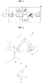
- FIG. 2 shows an example of use of the X-ray irradiating device according to the present invention.
- the X-ray irradiating device 100 may be utilized by being connected to a standard arm 200.
- the standard arm 200 connects the X-ray irradiating device 100 with a structure 300 fixed on a wall or the ground through multiple axis, and allows the radiographer to easily adjust the position of the X-ray irradiating device 100 while support the load thereof.
- the X-ray irradiating device 100 may be utilized in the movable form having a handle 60 to allow the radiographer to grip the handle by a hand.
- the shape of the handle 60 shown in the drawing is only one example, so various changes in the shape of the handle may be possible as long as it allows the radiographer to easily adjust the position of the X-ray irradiating device 100, that is, the irradiating direction of the X-ray beam.
- it may have a shape similar to a camera grip.
- FIGS. 3 to 6 Reference will be made to an X-ray imaging method using and X-ray irradiating device according to an embodiment of the present invention, with reference to FIGS. 3 to 6 .
- the following description will not only help to understand the configuration of the X-ray imaging method according to one aspect of the present invention, but will also help to better understand the configuration of the X-ray imaging apparatus according to one aspect of the present invention.
- FIG. 3 shows an example of selecting an automatic radiographic mode using the X-ray irradiating device according to an embodiment of the present invention.
- FIG. 3A schematically shows the process of radiographing maxillary molar teeth as an example.
- the radiographer aligns the irradiating direction of X-rays of the X-ray irradiating device 100 with the Frankfurt line by using the visible light beam of the auxiliary beam emitter 50, and sets the reference plane by pressing the reference plane set button 35.
- the controller 20 identifies the signal value of the motion sensor 30 in this position as the initial value representing the reference plane.
- the controller 20 identifies that the pointing angle is +30 degrees using the difference of the above described initial value of the signal value of the motion sensor 30.
- the controller 20 searches for the corresponding radiographic mode in the lookup table preset and stored in the memory by using the identified pointing angle, and automatically sets the radiographic mode.
- the radiographic mode selection result and the corresponding set value may be displayed on the display unit 41 as shown in the enlarged view 41z.
- the controller 20 may load the set value for the dose of X-ray radiation or the X-ray emitting time corresponding to the selected radiographic mode from the memory, and may control the X-ray source accordingly. For example, for the radiographic mode of the maxillary molar teeth, it is possible to control the X-ray source to irradiate the X-ray beam for a preset time of 0.08 seconds. Meanwhile, the X-ray irradiating device 100 may inform the radiographer via sound through a speaker that the automatic radiographic mode has been selected.
- FIG. 3B schematically shows the process of radiographing mandibular anterior teeth as another example.
- the radiographer aligns the position of the X-ray irradiating device 100 with the occlusal plane by using the auxiliary beam emitter 50, and sets the reference plane by pressing the reference plane set button 35.
- the controller 20 identifies the signal value of the motion sensor 30 in this position as the initial value representing the reference plane.
- the controller 20 automatically selects the mandibular anterior teeth radiographic mode through the procedures similar to those described above with reference to FIG. 3A , and controls the X-ray source using the corresponding set value.
- the set value of the X-ray beam emitting time corresponding to the radiographic mode shown in FIG. 3B may be different from that of FIG. 3A .
- FIG. 4 shows an example of an appropriate radiographing angle according to a subject in intraoral radiography.
- This drawing shows examples of various scenes of performing radiography of various subjects and the corresponding radiographing angles when performing radiography using the intraoral X-ray sensor and the X-ray irradiating device.
- the described radiographing angle is an example of a representative value or a range of angles recommended for radiographing for each subject, and the reference plane may be different from each other. It can be understood from this drawing that the appropriate radiographing angles are different for each tooth to be radiographed and it can be used as a reference value for selecting the radiographic mode.
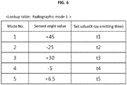
- FIG. 5 shows an example of a lookup table for the automatic radiographic mode used for an X-ray imaging apparatus and an X-ray imaging method using the same according to an embodiment of the present invention.
- the lookup table shown in the drawing may include a radiographic mode to be selected according to a sensed angle value representing a pointing angle with respect to a reference plane, and a set value corresponding to the radiographic mode, for example, an X-ray emitting time.
- the lookup table may be processed into a predetermined data format readable by the controller and stored in the memory.
- the lookup table shown here is only one example and may be modified into various forms.
- the sensed angle value may be given in a predetermined range rather than a specific value.
- the sensed angle value may be given as a unit of the signal value provided by the motion sensor, not the value converted to the actual angle.
- the lookup table may include tube current and tube voltage information according to each radiographic mode, as a set value corresponding to the radiographic mode, separately or in parallel with the X-ray emitting time. There are many other variations available.
- FIG. 6 shows an example of the X-ray imaging method according to an embodiment of the present invention.
- the X-ray imaging method uses the above described X-ray imaging apparatus, and includes: setting a reference plane as a reference value for a pointing angle in which an X-ray source is directed; detecting the pointing angle relative to the reference plane by using a motion sensor, and selecting a radiographic mode corresponding to the detected pointing angle; and performing radiography by controlling the X-ray source with a preset value corresponding to the selected radiographic mode.
- the X-ray imaging method may further include a step of selecting another automatic radiographic mode, that is, detecting a pattern of motion such as shaking or tilting the X-ray irradiating device by using the motion sensor, and selecting a radiographic mode according to the detected pattern of motion.
- the step of selecting the radiographic mode may include selecting the radiographic mode corresponding to the detected pointing angle with reference to a lookup table pre-input in a memory of an X-ray irradiating device when the pointing angle relative to the reference plane is detected by the motion sensor, and loading the set value according to the selected radiographic mode to a controller of the X-ray irradiating device.
- radiographic mode 1 a group of radiographic modes, which vary according to the size and position of the teeth to be radiographed, is defined as radiographic mode 1
- radiographic mode 2 a group of radiographic modes, which vary according to the age and body size of the examinee, is defined as radiographic mode 2, which will be described in more detail as follows.
- the step of setting the reference plane (S1) has been described hereinbefore, with reference to FIG. 3 .
- the step of automatically setting the radiographic mode 1 (S2) the step of sensing an angle by using the motion sensor (S21), and the step of automatically selecting the radiographic mode 1 by identifying the tooth to be radiographed according to the sensed angle are also the same as described above.
- the step of automatically setting the radiographic mode 2 may be performed before or after the step of setting the reference plane (S1) or after the step of automatically setting the radiographic mode 1 (S2).
- the step of automatically setting the radiographic mode 2 (S3) may include the step of sensing a motion such as shaking or tilting the X-ray imaging apparatus by using a motion sensor (S31), and the step of automatically selecting the radiographic mode 2 according to the sensed pattern of motion (S32).
- the dose of X-ray radiation may vary depending on whether the examinee is an adult or a child, and depending on the head size and weight of the examinee.
- the radiographic mode 2 may be classified into, for example, an adult radiographic mode, a child radiographic mode, and an obese radiographic mode in consideration of these characteristics. According to the classification of the radiographic mode 2, it is possible to collectively adjust the set value according to the radiographic mode 1 by a predetermined ratio or an offset value.
- the various motion patterns may be quantified or functioned as characteristic patterns of the signal value of the motion sensor, and the quantified or functioned patterns of the signal value may be stored in the memory in the form of a lookup table for the radiographic mode 2 and utilized in the same manner as in the selection of the radiographic mode 1.
- algorithms for identifying motion patterns from patterns of the signal value of the motion sensor may be implemented in a variety of ways.
- the present invention may be used directly in the field of dental radiography.
Landscapes
- Health & Medical Sciences (AREA)
- Life Sciences & Earth Sciences (AREA)
- Engineering & Computer Science (AREA)
- Medical Informatics (AREA)
- Physics & Mathematics (AREA)
- Optics & Photonics (AREA)
- Heart & Thoracic Surgery (AREA)
- Veterinary Medicine (AREA)
- Biophysics (AREA)
- High Energy & Nuclear Physics (AREA)
- Public Health (AREA)
- Nuclear Medicine, Radiotherapy & Molecular Imaging (AREA)
- General Health & Medical Sciences (AREA)
- Pathology (AREA)
- Radiology & Medical Imaging (AREA)
- Biomedical Technology (AREA)
- Animal Behavior & Ethology (AREA)
- Molecular Biology (AREA)
- Surgery (AREA)
- Theoretical Computer Science (AREA)
- General Engineering & Computer Science (AREA)
- Dentistry (AREA)
- Oral & Maxillofacial Surgery (AREA)
- Human Computer Interaction (AREA)
- General Physics & Mathematics (AREA)
- Apparatus For Radiation Diagnosis (AREA)
Claims (7)
- Röntgenstrahlvorrichtung für die intraorale Radiographie, umfassend:eine Röntgenquelle (10);einen Bewegungssensor (30), der so konfiguriert ist, dass er einen Richtungswinkel der Röntgenquelle relativ zu einer festgelegten Referenzebene erfasst; undeine Steuereinheit (20), die so konfiguriert ist, dass sie einen von mehreren radiografischen Modi gemäß einem von dem Bewegungssensor empfangenen Zeigewinkelsignal auswählt,dadurch gekennzeichnet, dassdie Röntgenmodi je nach Größe und Position der zu röntgenden Zähne variieren, und die Steuerung die Dosis der Röntgenstrahlung steuert, indem sie die Röntgenstrahlungs-Emissionszeit und/oder die Röhrenspannung und/oder den Röhrenstrom der Röntgenquelle für die Röntgenaufnahme entsprechend den ausgewählten Röntgenmodi steuert.
- Röntgenstrahlvorrichtung nach Anspruch 1, weiter umfassend:
einen Speicher (21), der mit der Steuereinheit (20) verbunden und so konfiguriert ist, dass er eine Nachschlagetabelle der eingestellten Werte zur Durchführung des entsprechend dem Ausrichtungswinkel ausgewählten Röntgenmodus speichert. - Röntgenstrahlvorrichtung nach Anspruch 1, weiterhin umfassend:
einen Speicher (21), der mit der Steuereinheit (20) verbunden ist und so konfiguriert ist, dass er eine Nachschlagetabelle der Einstellwerte für die Durchführung des radiographischen Modus speichert, der gemäß dem Ausrichtungswinkel ausgewählt wurde:einen Hilfsstrahlemitter (50), der so konfiguriert ist, dass er die Ausrichtungsrichtung der Röntgenquelle durch Emittieren eines sichtbaren Strahls anzeigt; undeinen Bezugsebenen-Einstellknopf, der so konfiguriert ist, dass er die Ausrichtungsrichtung der Röntgenquelle als Bezugswert für die Berechnung des Ausrichtungswinkelsignals mit dem Eingang eines Radiographen einstellt. - Intra-orales Röntgenbildgebungsverfahren, umfassend:Festlegen einer Referenzebene als Referenzwert für einen Zeigewinkel;Erfassen eines Ausrichtungswinkels einer Röntgenquelle relativ zu der Referenzebene unter Verwendung eines Bewegungssensors (30); Auswählen eines Röntgenmodus aus einer Vielzahl von Röntgenmodi, die je nach Position und Größe der zu röntgenden Zähne variieren, gemäß einem von dem Bewegungssensor empfangenen Ausrichtungswinkelsignal; undDurchführung intraoraler Radiographie durch Steuerung der Dosis der von der Röntgenquelle emittierten Röntgenstrahlung entsprechend dem gewählten radiographischen Modus.
- Röntgenbildgebungsverfahren nach Anspruch 4, wobei das Auswählen des Röntgenmodus umfasst:Auswählen des Röntgenmodus entsprechend dem erfassten Ausrichtungswinkel unter Bezugnahme auf eine Nachschlagetabelle, die in einem Speicher einer Röntgenstrahlvorrichtung vorab eingegeben wurde, wenn der Ausrichtungswinkel in Bezug auf die Referenzebene durch den Bewegungssensor erfasst wird, undLaden des Einstellwerts gemäß dem ausgewählten Röntgenmodus in eine Steuerung der Röntgenstrahlvorrichtung.
- Röntgenstrahlvorrichtung nach Anspruch 1,
wobei die Steuerung den Ausrichtungswinkel identifiziert, wenn der Ausrichtungswinkel der Röntgenquelle für eine vorbestimmte Zeit beibehalten wird. - Röntgenstrahlvorrichtung nach Anspruch 1 umfasst ferner:
eine Anzeigeeinheit, die so konfiguriert ist, dass sie den ausgewählten Röntgenmodus anzeigt.
Priority Applications (1)
| Application Number | Priority Date | Filing Date | Title |
|---|---|---|---|
| EP20200511.2A EP3777690A1 (de) | 2015-04-20 | 2016-04-20 | Röntgenbestrahlungsvorrichtung mit bewegungssensor und röntgenbildgebungsverfahren mit verwendung davon |
Applications Claiming Priority (2)
| Application Number | Priority Date | Filing Date | Title |
|---|---|---|---|
| KR1020150055237A KR102377484B1 (ko) | 2015-04-20 | 2015-04-20 | 모션 센서를 구비한 엑스선 조사 장치 및 이를 이용한 엑스선 촬영 방법 |
| PCT/KR2016/004101 WO2016171462A1 (ko) | 2015-04-20 | 2016-04-20 | 모션 센서를 구비한 엑스선 조사 장치 및 이를 이용한 엑스선 촬영 방법 |
Related Child Applications (2)
| Application Number | Title | Priority Date | Filing Date |
|---|---|---|---|
| EP20200511.2A Division-Into EP3777690A1 (de) | 2015-04-20 | 2016-04-20 | Röntgenbestrahlungsvorrichtung mit bewegungssensor und röntgenbildgebungsverfahren mit verwendung davon |
| EP20200511.2A Division EP3777690A1 (de) | 2015-04-20 | 2016-04-20 | Röntgenbestrahlungsvorrichtung mit bewegungssensor und röntgenbildgebungsverfahren mit verwendung davon |
Publications (3)
| Publication Number | Publication Date |
|---|---|
| EP3287076A1 EP3287076A1 (de) | 2018-02-28 |
| EP3287076A4 EP3287076A4 (de) | 2019-01-23 |
| EP3287076B1 true EP3287076B1 (de) | 2020-11-18 |
Family
ID=57144087
Family Applications (2)
| Application Number | Title | Priority Date | Filing Date |
|---|---|---|---|
| EP20200511.2A Pending EP3777690A1 (de) | 2015-04-20 | 2016-04-20 | Röntgenbestrahlungsvorrichtung mit bewegungssensor und röntgenbildgebungsverfahren mit verwendung davon |
| EP16783395.3A Active EP3287076B1 (de) | 2015-04-20 | 2016-04-20 | Röntgenstrahlenvorrichtung mit bewegungssensor und röntgenbildgebungsverfahren damit |
Family Applications Before (1)
| Application Number | Title | Priority Date | Filing Date |
|---|---|---|---|
| EP20200511.2A Pending EP3777690A1 (de) | 2015-04-20 | 2016-04-20 | Röntgenbestrahlungsvorrichtung mit bewegungssensor und röntgenbildgebungsverfahren mit verwendung davon |
Country Status (5)
| Country | Link |
|---|---|
| US (1) | US10610189B2 (de) |
| EP (2) | EP3777690A1 (de) |
| KR (1) | KR102377484B1 (de) |
| CN (1) | CN107735029B (de) |
| WO (1) | WO2016171462A1 (de) |
Families Citing this family (6)
| Publication number | Priority date | Publication date | Assignee | Title |
|---|---|---|---|---|
| JP7278073B2 (ja) * | 2018-12-27 | 2023-05-19 | キヤノン株式会社 | 制御装置、表示方法及び放射線撮像装置 |
| EP3777693B1 (de) * | 2019-08-12 | 2022-03-16 | DENTSPLY SIRONA Inc. | Mess- und datenkommunikationsvorrichtung für ein intraorales zahnärztliches radiologiesystem |
| CN110859640A (zh) * | 2019-11-13 | 2020-03-06 | 先临三维科技股份有限公司 | 扫描仪、及其操作方法、装置、系统、存储介质和处理器 |
| CN113288199A (zh) * | 2021-06-11 | 2021-08-24 | 常州赛乐医疗技术有限公司 | 带有倾斜角度监测的牙科x射线机及其工作方法 |
| KR20230083443A (ko) | 2021-12-03 | 2023-06-12 | 주식회사 엘앤씨에이아이 | 뇌질환 진단용 이동형 cbct 영상 처리 장치 |
| CN114708752A (zh) * | 2022-01-12 | 2022-07-05 | 南京九阵维医疗科技有限公司 | 牙科根尖片虚拟教学系统及虚拟根尖片的获取方法 |
Family Cites Families (37)
| Publication number | Priority date | Publication date | Assignee | Title |
|---|---|---|---|---|
| DE2404469A1 (de) * | 1974-01-31 | 1975-08-07 | Ritter Ag | Elektronisches roentgenschaltgeraet fuer dentalzwecke |
| US5572567A (en) * | 1994-12-08 | 1996-11-05 | Continental X-Ray Corp. | Universal radiographic room |
| US7386339B2 (en) * | 1999-05-18 | 2008-06-10 | Mediguide Ltd. | Medical imaging and navigation system |
| JP3848082B2 (ja) * | 2000-12-27 | 2006-11-22 | キヤノン株式会社 | X線画像撮影装置及び方法、制御装置及び方法 |
| DE10301891B3 (de) * | 2003-01-17 | 2004-10-21 | Siemens Ag | Verfahren zum Betrieb eines Röntgen-Tomographie-Geräts und Röntgen-Tomographie-Gerät |
| JP4056922B2 (ja) * | 2003-04-21 | 2008-03-05 | ジーイー・メディカル・システムズ・グローバル・テクノロジー・カンパニー・エルエルシー | 放射線計算断層画像装置 |
| JP4509493B2 (ja) * | 2003-04-25 | 2010-07-21 | ジーイー・メディカル・システムズ・グローバル・テクノロジー・カンパニー・エルエルシー | X線ct画像撮影方法およびx線ct装置 |
| WO2005000121A1 (en) * | 2003-06-30 | 2005-01-06 | Koninklijke Philips Electronics N.V. | Contour and scout scanning technique for pulsed x-ray large area ct detectors |
| JP2006262989A (ja) * | 2005-03-22 | 2006-10-05 | Toshiba Corp | X線診断装置 |
| US20070242868A1 (en) * | 2005-11-09 | 2007-10-18 | Dexela Limited | Methods and apparatus for displaying images |
| US7545907B2 (en) * | 2005-11-09 | 2009-06-09 | Dexela Limited | Methods and apparatus for obtaining low-dose imaging |
| US7983457B2 (en) * | 2005-11-23 | 2011-07-19 | General Electric Company | Method and system for automatically determining regions in a scanned object |
| DE102006003829A1 (de) * | 2006-01-26 | 2007-08-16 | Siemens Ag | Röntgen-Computertomograf und Verfahren zum Betreiben eines Röntgen-Computertomografen |
| US7331711B2 (en) * | 2006-05-02 | 2008-02-19 | Siemens Aktiengesellschaft | Method and foot switch control for fast angulation changes in an x-ray system |
| US8005284B2 (en) * | 2006-12-07 | 2011-08-23 | Kabushiki Kaisha Toshiba | Three dimensional image processing apparatus and x-ray diagnosis apparatus |
| JP5039064B2 (ja) * | 2007-02-14 | 2012-10-03 | 株式会社日立メディコ | X線ct装置 |
| DE102007008962A1 (de) * | 2007-02-21 | 2008-08-28 | Sirona Dental Systems Gmbh | Dentale Kleinröntgeneinrichtung und Verfahren zur Positionierung eines Röntgenstrahlers |
| JP4739278B2 (ja) * | 2007-05-11 | 2011-08-03 | 株式会社モリタ製作所 | X線ct撮影装置 |
| JP5032229B2 (ja) * | 2007-07-20 | 2012-09-26 | 富士フイルム株式会社 | 放射線画像撮像装置及び撮像方法 |
| JP5398133B2 (ja) * | 2007-10-23 | 2014-01-29 | キヤノン株式会社 | X線撮影装置、x線撮影装置の制御方法、プログラム及び記憶媒体 |
| KR100850500B1 (ko) * | 2008-01-08 | 2008-08-05 | 주식회사 포스콤 | 작고 가볍게 제작 가능한 x선 촬영 장치 |
| US8744039B2 (en) * | 2008-07-04 | 2014-06-03 | Hitachi Medical Corporation | X-ray CT apparatus |
| EP2328477B1 (de) * | 2008-08-04 | 2018-05-16 | Koninklijke Philips N.V. | Interventionelle bildgebung und datenaufbereitung |
| JP5569951B2 (ja) * | 2008-09-01 | 2014-08-13 | 学校法人日本大学 | 頭部用x線ct撮影装置及びその撮影制御方法 |
| US9492129B2 (en) * | 2008-10-27 | 2016-11-15 | Dental Imaging Technologies Corporation | Triggering of intraoral X-ray sensor using pixel array sub-sampling |
| CN101926650B (zh) * | 2009-06-26 | 2014-04-30 | Ge医疗系统环球技术有限公司 | 实际皮肤入射剂量率计算装置及方法和x光机 |
| JP4998531B2 (ja) * | 2009-09-30 | 2012-08-15 | 株式会社島津製作所 | X線撮影装置 |
| CN101750428B (zh) * | 2009-12-30 | 2011-07-27 | 王亚楠 | 一种利用x射线摄影探查患者头部中人工耳蜗的方法 |
| JP5774302B2 (ja) * | 2010-12-20 | 2015-09-09 | ジーイー・メディカル・システムズ・グローバル・テクノロジー・カンパニー・エルエルシー | X線ct装置 |
| FI123713B (fi) * | 2011-03-21 | 2013-09-30 | Planmeca Oy | Järjestely intraoraaliröntgenkuvantamisen yhteydessä |
| US8670521B2 (en) * | 2011-06-02 | 2014-03-11 | Carestream Health, Inc. | Method for generating an intraoral volume image |
| CN104039228B (zh) * | 2011-11-15 | 2017-06-30 | 未来解决方案有限公司 | 用于产生x射线图像的装置、系统和方法 |
| CN103284740B (zh) * | 2012-02-28 | 2016-02-24 | 上海西门子医疗器械有限公司 | Ct机的扫描控制方法、扫描控制装置及ct机 |
| JP6076822B2 (ja) * | 2012-05-02 | 2017-02-08 | 株式会社モリタ製作所 | X線ct撮影装置 |
| JP5756790B2 (ja) * | 2012-11-08 | 2015-07-29 | 株式会社モリタ製作所 | X線撮影装置 |
| JP2014226475A (ja) * | 2013-05-27 | 2014-12-08 | 株式会社東芝 | X線コンピュータ断層撮影装置 |
| CN104287756B (zh) * | 2014-09-28 | 2017-03-08 | 上海联影医疗科技有限公司 | X射线图像获取方法及装置 |
-
2015
- 2015-04-20 KR KR1020150055237A patent/KR102377484B1/ko active Active
-
2016
- 2016-04-20 EP EP20200511.2A patent/EP3777690A1/de active Pending
- 2016-04-20 CN CN201680035743.XA patent/CN107735029B/zh active Active
- 2016-04-20 US US15/567,962 patent/US10610189B2/en active Active
- 2016-04-20 WO PCT/KR2016/004101 patent/WO2016171462A1/ko not_active Ceased
- 2016-04-20 EP EP16783395.3A patent/EP3287076B1/de active Active
Also Published As
| Publication number | Publication date |
|---|---|
| US20180132813A1 (en) | 2018-05-17 |
| CN107735029B (zh) | 2021-09-14 |
| KR102377484B1 (ko) | 2022-03-22 |
| EP3287076A4 (de) | 2019-01-23 |
| US10610189B2 (en) | 2020-04-07 |
| CN107735029A (zh) | 2018-02-23 |
| EP3287076A1 (de) | 2018-02-28 |
| KR20160124515A (ko) | 2016-10-28 |
| EP3777690A1 (de) | 2021-02-17 |
| WO2016171462A1 (ko) | 2016-10-27 |
Similar Documents
| Publication | Publication Date | Title |
|---|---|---|
| EP3287076B1 (de) | Röntgenstrahlenvorrichtung mit bewegungssensor und röntgenbildgebungsverfahren damit | |
| EP3066984A2 (de) | Positionsbestimmung eines intraoralen sensors | |
| CN107708569B (zh) | 放射线照射装置、放射线照射装置的控制方法及存储介质 | |
| KR102374444B1 (ko) | X-선 촬영에서 자동화된 선량 제어 시스템 및 방법 | |
| US9907530B2 (en) | Automated control of image exposure parameters in an intra-oral x-ray system | |
| US9119575B2 (en) | Panoramic tomography X-ray apparatus and image processing device | |
| CN107847203A (zh) | 放射线照射装置、放射线照射装置的控制方法以及程序 | |
| CN104010573A (zh) | X射线诊断装置以及x射线诊断装置的控制方法 | |
| EP3967234B1 (de) | Positionierungsführungssystem für röntgenuntersuchungen | |
| US10702224B1 (en) | Positioning guidance system For X-ray exams | |
| JP2016190009A (ja) | 放射線画像撮影装置、並びに放射線画像撮影装置の制御方法およびプログラム | |
| JP5595184B2 (ja) | 放射線画像撮影装置および放射線画像撮影方法 | |
| JP2015188611A (ja) | デジタルパノラマx線撮影装置及び歯科用ct装置 | |
| US10506997B2 (en) | X-ray diagnostic apparatus | |
| JP6435938B2 (ja) | X線撮影装置 | |
| CN103281960B (zh) | 荧光透视系统和方法 | |
| JP7278053B2 (ja) | X線ctシステム | |
| JP6972810B2 (ja) | 放射線制御装置 | |
| JP2011229559A5 (de) | ||
| JP5570351B2 (ja) | コンソール、入力端末、および、x線画像撮影システム | |
| JP7283470B2 (ja) | 放射線撮影装置 | |
| JP2009279295A (ja) | 放射線画像撮影装置及び画像処理装置 | |
| JP2020178997A (ja) | 放射線撮影装置 | |
| JP2025105129A (ja) | X線照射システム | |
| JP2012000125A (ja) | 放射線撮影装置 |
Legal Events
| Date | Code | Title | Description |
|---|---|---|---|
| STAA | Information on the status of an ep patent application or granted ep patent |
Free format text: STATUS: THE INTERNATIONAL PUBLICATION HAS BEEN MADE |
|
| PUAI | Public reference made under article 153(3) epc to a published international application that has entered the european phase |
Free format text: ORIGINAL CODE: 0009012 |
|
| STAA | Information on the status of an ep patent application or granted ep patent |
Free format text: STATUS: REQUEST FOR EXAMINATION WAS MADE |
|
| 17P | Request for examination filed |
Effective date: 20171026 |
|
| AK | Designated contracting states |
Kind code of ref document: A1 Designated state(s): AL AT BE BG CH CY CZ DE DK EE ES FI FR GB GR HR HU IE IS IT LI LT LU LV MC MK MT NL NO PL PT RO RS SE SI SK SM TR |
|
| AX | Request for extension of the european patent |
Extension state: BA ME |
|
| DAV | Request for validation of the european patent (deleted) | ||
| DAX | Request for extension of the european patent (deleted) | ||
| A4 | Supplementary search report drawn up and despatched |
Effective date: 20190103 |
|
| RIC1 | Information provided on ipc code assigned before grant |
Ipc: A61B 6/08 20060101ALI20181219BHEP Ipc: A61B 6/14 20060101ALI20181219BHEP Ipc: G06F 3/01 20060101ALI20181219BHEP Ipc: A61B 6/00 20060101AFI20181219BHEP |
|
| GRAP | Despatch of communication of intention to grant a patent |
Free format text: ORIGINAL CODE: EPIDOSNIGR1 |
|
| STAA | Information on the status of an ep patent application or granted ep patent |
Free format text: STATUS: GRANT OF PATENT IS INTENDED |
|
| INTG | Intention to grant announced |
Effective date: 20200728 |
|
| GRAS | Grant fee paid |
Free format text: ORIGINAL CODE: EPIDOSNIGR3 |
|
| GRAA | (expected) grant |
Free format text: ORIGINAL CODE: 0009210 |
|
| STAA | Information on the status of an ep patent application or granted ep patent |
Free format text: STATUS: THE PATENT HAS BEEN GRANTED |
|
| AK | Designated contracting states |
Kind code of ref document: B1 Designated state(s): AL AT BE BG CH CY CZ DE DK EE ES FI FR GB GR HR HU IE IS IT LI LT LU LV MC MK MT NL NO PL PT RO RS SE SI SK SM TR |
|
| REG | Reference to a national code |
Ref country code: GB Ref legal event code: FG4D |
|
| REG | Reference to a national code |
Ref country code: CH Ref legal event code: EP |
|
| REG | Reference to a national code |
Ref country code: IE Ref legal event code: FG4D |
|
| REG | Reference to a national code |
Ref country code: DE Ref legal event code: R096 Ref document number: 602016048153 Country of ref document: DE |
|
| REG | Reference to a national code |
Ref country code: AT Ref legal event code: REF Ref document number: 1334857 Country of ref document: AT Kind code of ref document: T Effective date: 20201215 |
|
| REG | Reference to a national code |
Ref country code: FI Ref legal event code: FGE |
|
| REG | Reference to a national code |
Ref country code: AT Ref legal event code: MK05 Ref document number: 1334857 Country of ref document: AT Kind code of ref document: T Effective date: 20201118 |
|
| REG | Reference to a national code |
Ref country code: NL Ref legal event code: MP Effective date: 20201118 |
|
| PG25 | Lapsed in a contracting state [announced via postgrant information from national office to epo] |
Ref country code: GR Free format text: LAPSE BECAUSE OF FAILURE TO SUBMIT A TRANSLATION OF THE DESCRIPTION OR TO PAY THE FEE WITHIN THE PRESCRIBED TIME-LIMIT Effective date: 20210219 Ref country code: NO Free format text: LAPSE BECAUSE OF FAILURE TO SUBMIT A TRANSLATION OF THE DESCRIPTION OR TO PAY THE FEE WITHIN THE PRESCRIBED TIME-LIMIT Effective date: 20210218 Ref country code: PT Free format text: LAPSE BECAUSE OF FAILURE TO SUBMIT A TRANSLATION OF THE DESCRIPTION OR TO PAY THE FEE WITHIN THE PRESCRIBED TIME-LIMIT Effective date: 20210318 Ref country code: RS Free format text: LAPSE BECAUSE OF FAILURE TO SUBMIT A TRANSLATION OF THE DESCRIPTION OR TO PAY THE FEE WITHIN THE PRESCRIBED TIME-LIMIT Effective date: 20201118 |
|
| PG25 | Lapsed in a contracting state [announced via postgrant information from national office to epo] |
Ref country code: SE Free format text: LAPSE BECAUSE OF FAILURE TO SUBMIT A TRANSLATION OF THE DESCRIPTION OR TO PAY THE FEE WITHIN THE PRESCRIBED TIME-LIMIT Effective date: 20201118 Ref country code: BG Free format text: LAPSE BECAUSE OF FAILURE TO SUBMIT A TRANSLATION OF THE DESCRIPTION OR TO PAY THE FEE WITHIN THE PRESCRIBED TIME-LIMIT Effective date: 20210218 Ref country code: LV Free format text: LAPSE BECAUSE OF FAILURE TO SUBMIT A TRANSLATION OF THE DESCRIPTION OR TO PAY THE FEE WITHIN THE PRESCRIBED TIME-LIMIT Effective date: 20201118 Ref country code: IS Free format text: LAPSE BECAUSE OF FAILURE TO SUBMIT A TRANSLATION OF THE DESCRIPTION OR TO PAY THE FEE WITHIN THE PRESCRIBED TIME-LIMIT Effective date: 20210318 Ref country code: PL Free format text: LAPSE BECAUSE OF FAILURE TO SUBMIT A TRANSLATION OF THE DESCRIPTION OR TO PAY THE FEE WITHIN THE PRESCRIBED TIME-LIMIT Effective date: 20201118 Ref country code: AT Free format text: LAPSE BECAUSE OF FAILURE TO SUBMIT A TRANSLATION OF THE DESCRIPTION OR TO PAY THE FEE WITHIN THE PRESCRIBED TIME-LIMIT Effective date: 20201118 |
|
| REG | Reference to a national code |
Ref country code: LT Ref legal event code: MG9D |
|
| PG25 | Lapsed in a contracting state [announced via postgrant information from national office to epo] |
Ref country code: HR Free format text: LAPSE BECAUSE OF FAILURE TO SUBMIT A TRANSLATION OF THE DESCRIPTION OR TO PAY THE FEE WITHIN THE PRESCRIBED TIME-LIMIT Effective date: 20201118 |
|
| PG25 | Lapsed in a contracting state [announced via postgrant information from national office to epo] |
Ref country code: SM Free format text: LAPSE BECAUSE OF FAILURE TO SUBMIT A TRANSLATION OF THE DESCRIPTION OR TO PAY THE FEE WITHIN THE PRESCRIBED TIME-LIMIT Effective date: 20201118 Ref country code: LT Free format text: LAPSE BECAUSE OF FAILURE TO SUBMIT A TRANSLATION OF THE DESCRIPTION OR TO PAY THE FEE WITHIN THE PRESCRIBED TIME-LIMIT Effective date: 20201118 Ref country code: EE Free format text: LAPSE BECAUSE OF FAILURE TO SUBMIT A TRANSLATION OF THE DESCRIPTION OR TO PAY THE FEE WITHIN THE PRESCRIBED TIME-LIMIT Effective date: 20201118 Ref country code: CZ Free format text: LAPSE BECAUSE OF FAILURE TO SUBMIT A TRANSLATION OF THE DESCRIPTION OR TO PAY THE FEE WITHIN THE PRESCRIBED TIME-LIMIT Effective date: 20201118 Ref country code: RO Free format text: LAPSE BECAUSE OF FAILURE TO SUBMIT A TRANSLATION OF THE DESCRIPTION OR TO PAY THE FEE WITHIN THE PRESCRIBED TIME-LIMIT Effective date: 20201118 Ref country code: SK Free format text: LAPSE BECAUSE OF FAILURE TO SUBMIT A TRANSLATION OF THE DESCRIPTION OR TO PAY THE FEE WITHIN THE PRESCRIBED TIME-LIMIT Effective date: 20201118 |
|
| REG | Reference to a national code |
Ref country code: DE Ref legal event code: R097 Ref document number: 602016048153 Country of ref document: DE |
|
| PG25 | Lapsed in a contracting state [announced via postgrant information from national office to epo] |
Ref country code: DK Free format text: LAPSE BECAUSE OF FAILURE TO SUBMIT A TRANSLATION OF THE DESCRIPTION OR TO PAY THE FEE WITHIN THE PRESCRIBED TIME-LIMIT Effective date: 20201118 |
|
| PLBE | No opposition filed within time limit |
Free format text: ORIGINAL CODE: 0009261 |
|
| STAA | Information on the status of an ep patent application or granted ep patent |
Free format text: STATUS: NO OPPOSITION FILED WITHIN TIME LIMIT |
|
| 26N | No opposition filed |
Effective date: 20210819 |
|
| PG25 | Lapsed in a contracting state [announced via postgrant information from national office to epo] |
Ref country code: AL Free format text: LAPSE BECAUSE OF FAILURE TO SUBMIT A TRANSLATION OF THE DESCRIPTION OR TO PAY THE FEE WITHIN THE PRESCRIBED TIME-LIMIT Effective date: 20201118 Ref country code: NL Free format text: LAPSE BECAUSE OF FAILURE TO SUBMIT A TRANSLATION OF THE DESCRIPTION OR TO PAY THE FEE WITHIN THE PRESCRIBED TIME-LIMIT Effective date: 20201118 |
|
| PG25 | Lapsed in a contracting state [announced via postgrant information from national office to epo] |
Ref country code: SI Free format text: LAPSE BECAUSE OF FAILURE TO SUBMIT A TRANSLATION OF THE DESCRIPTION OR TO PAY THE FEE WITHIN THE PRESCRIBED TIME-LIMIT Effective date: 20201118 Ref country code: MC Free format text: LAPSE BECAUSE OF FAILURE TO SUBMIT A TRANSLATION OF THE DESCRIPTION OR TO PAY THE FEE WITHIN THE PRESCRIBED TIME-LIMIT Effective date: 20201118 |
|
| PG25 | Lapsed in a contracting state [announced via postgrant information from national office to epo] |
Ref country code: LU Free format text: LAPSE BECAUSE OF NON-PAYMENT OF DUE FEES Effective date: 20210420 |
|
| REG | Reference to a national code |
Ref country code: BE Ref legal event code: MM Effective date: 20210430 |
|
| PG25 | Lapsed in a contracting state [announced via postgrant information from national office to epo] |
Ref country code: ES Free format text: LAPSE BECAUSE OF FAILURE TO SUBMIT A TRANSLATION OF THE DESCRIPTION OR TO PAY THE FEE WITHIN THE PRESCRIBED TIME-LIMIT Effective date: 20201118 Ref country code: LI Free format text: LAPSE BECAUSE OF NON-PAYMENT OF DUE FEES Effective date: 20210430 Ref country code: CH Free format text: LAPSE BECAUSE OF NON-PAYMENT OF DUE FEES Effective date: 20210430 |
|
| PG25 | Lapsed in a contracting state [announced via postgrant information from national office to epo] |
Ref country code: IE Free format text: LAPSE BECAUSE OF NON-PAYMENT OF DUE FEES Effective date: 20210420 |
|
| PG25 | Lapsed in a contracting state [announced via postgrant information from national office to epo] |
Ref country code: IS Free format text: LAPSE BECAUSE OF FAILURE TO SUBMIT A TRANSLATION OF THE DESCRIPTION OR TO PAY THE FEE WITHIN THE PRESCRIBED TIME-LIMIT Effective date: 20210318 |
|
| PG25 | Lapsed in a contracting state [announced via postgrant information from national office to epo] |
Ref country code: BE Free format text: LAPSE BECAUSE OF NON-PAYMENT OF DUE FEES Effective date: 20210430 |
|
| PG25 | Lapsed in a contracting state [announced via postgrant information from national office to epo] |
Ref country code: HU Free format text: LAPSE BECAUSE OF FAILURE TO SUBMIT A TRANSLATION OF THE DESCRIPTION OR TO PAY THE FEE WITHIN THE PRESCRIBED TIME-LIMIT; INVALID AB INITIO Effective date: 20160420 |
|
| PG25 | Lapsed in a contracting state [announced via postgrant information from national office to epo] |
Ref country code: CY Free format text: LAPSE BECAUSE OF FAILURE TO SUBMIT A TRANSLATION OF THE DESCRIPTION OR TO PAY THE FEE WITHIN THE PRESCRIBED TIME-LIMIT Effective date: 20201118 |
|
| P01 | Opt-out of the competence of the unified patent court (upc) registered |
Effective date: 20230526 |
|
| PG25 | Lapsed in a contracting state [announced via postgrant information from national office to epo] |
Ref country code: MK Free format text: LAPSE BECAUSE OF FAILURE TO SUBMIT A TRANSLATION OF THE DESCRIPTION OR TO PAY THE FEE WITHIN THE PRESCRIBED TIME-LIMIT Effective date: 20201118 |
|
| PG25 | Lapsed in a contracting state [announced via postgrant information from national office to epo] |
Ref country code: TR Free format text: LAPSE BECAUSE OF FAILURE TO SUBMIT A TRANSLATION OF THE DESCRIPTION OR TO PAY THE FEE WITHIN THE PRESCRIBED TIME-LIMIT Effective date: 20201118 |
|
| PG25 | Lapsed in a contracting state [announced via postgrant information from national office to epo] |
Ref country code: MT Free format text: LAPSE BECAUSE OF FAILURE TO SUBMIT A TRANSLATION OF THE DESCRIPTION OR TO PAY THE FEE WITHIN THE PRESCRIBED TIME-LIMIT Effective date: 20201118 |
|
| PGFP | Annual fee paid to national office [announced via postgrant information from national office to epo] |
Ref country code: DE Payment date: 20250407 Year of fee payment: 10 |
|
| PGFP | Annual fee paid to national office [announced via postgrant information from national office to epo] |
Ref country code: IT Payment date: 20250408 Year of fee payment: 10 |
|
| PGFP | Annual fee paid to national office [announced via postgrant information from national office to epo] |
Ref country code: GB Payment date: 20260324 Year of fee payment: 11 |
|
| PGFP | Annual fee paid to national office [announced via postgrant information from national office to epo] |
Ref country code: FI Payment date: 20260323 Year of fee payment: 11 |
|
| PGFP | Annual fee paid to national office [announced via postgrant information from national office to epo] |
Ref country code: FR Payment date: 20260323 Year of fee payment: 11 |