EP3287226A2 - Werkstück zum reibschweissverfahren ; linear reibschweissverfahren - Google Patents
Werkstück zum reibschweissverfahren ; linear reibschweissverfahren Download PDFInfo
- Publication number
- EP3287226A2 EP3287226A2 EP17187703.8A EP17187703A EP3287226A2 EP 3287226 A2 EP3287226 A2 EP 3287226A2 EP 17187703 A EP17187703 A EP 17187703A EP 3287226 A2 EP3287226 A2 EP 3287226A2
- Authority
- EP
- European Patent Office
- Prior art keywords
- workpiece
- pyramidal
- angle
- weld
- flank
- Prior art date
- Legal status (The legal status is an assumption and is not a legal conclusion. Google has not performed a legal analysis and makes no representation as to the accuracy of the status listed.)
- Granted
Links
Images



Classifications
-
- B—PERFORMING OPERATIONS; TRANSPORTING
- B23—MACHINE TOOLS; METAL-WORKING NOT OTHERWISE PROVIDED FOR
- B23K—SOLDERING OR UNSOLDERING; WELDING; CLADDING OR PLATING BY SOLDERING OR WELDING; CUTTING BY APPLYING HEAT LOCALLY, e.g. FLAME CUTTING; WORKING BY LASER BEAM
- B23K20/00—Non-electric welding by applying impact or other pressure, with or without the application of heat, e.g. cladding or plating
- B23K20/12—Non-electric welding by applying impact or other pressure, with or without the application of heat, e.g. cladding or plating the heat being generated by friction; Friction welding
- B23K20/1205—Non-electric welding by applying impact or other pressure, with or without the application of heat, e.g. cladding or plating the heat being generated by friction; Friction welding using translation movement
-
- B—PERFORMING OPERATIONS; TRANSPORTING
- B23—MACHINE TOOLS; METAL-WORKING NOT OTHERWISE PROVIDED FOR
- B23K—SOLDERING OR UNSOLDERING; WELDING; CLADDING OR PLATING BY SOLDERING OR WELDING; CUTTING BY APPLYING HEAT LOCALLY, e.g. FLAME CUTTING; WORKING BY LASER BEAM
- B23K20/00—Non-electric welding by applying impact or other pressure, with or without the application of heat, e.g. cladding or plating
- B23K20/12—Non-electric welding by applying impact or other pressure, with or without the application of heat, e.g. cladding or plating the heat being generated by friction; Friction welding
- B23K20/122—Non-electric welding by applying impact or other pressure, with or without the application of heat, e.g. cladding or plating the heat being generated by friction; Friction welding using a non-consumable tool, e.g. friction stir welding
-
- B—PERFORMING OPERATIONS; TRANSPORTING
- B23—MACHINE TOOLS; METAL-WORKING NOT OTHERWISE PROVIDED FOR
- B23K—SOLDERING OR UNSOLDERING; WELDING; CLADDING OR PLATING BY SOLDERING OR WELDING; CUTTING BY APPLYING HEAT LOCALLY, e.g. FLAME CUTTING; WORKING BY LASER BEAM
- B23K20/00—Non-electric welding by applying impact or other pressure, with or without the application of heat, e.g. cladding or plating
- B23K20/002—Non-electric welding by applying impact or other pressure, with or without the application of heat, e.g. cladding or plating specially adapted for particular articles or work
-
- B—PERFORMING OPERATIONS; TRANSPORTING
- B23—MACHINE TOOLS; METAL-WORKING NOT OTHERWISE PROVIDED FOR
- B23K—SOLDERING OR UNSOLDERING; WELDING; CLADDING OR PLATING BY SOLDERING OR WELDING; CUTTING BY APPLYING HEAT LOCALLY, e.g. FLAME CUTTING; WORKING BY LASER BEAM
- B23K20/00—Non-electric welding by applying impact or other pressure, with or without the application of heat, e.g. cladding or plating
- B23K20/12—Non-electric welding by applying impact or other pressure, with or without the application of heat, e.g. cladding or plating the heat being generated by friction; Friction welding
-
- B—PERFORMING OPERATIONS; TRANSPORTING
- B23—MACHINE TOOLS; METAL-WORKING NOT OTHERWISE PROVIDED FOR
- B23K—SOLDERING OR UNSOLDERING; WELDING; CLADDING OR PLATING BY SOLDERING OR WELDING; CUTTING BY APPLYING HEAT LOCALLY, e.g. FLAME CUTTING; WORKING BY LASER BEAM
- B23K20/00—Non-electric welding by applying impact or other pressure, with or without the application of heat, e.g. cladding or plating
- B23K20/12—Non-electric welding by applying impact or other pressure, with or without the application of heat, e.g. cladding or plating the heat being generated by friction; Friction welding
- B23K20/129—Non-electric welding by applying impact or other pressure, with or without the application of heat, e.g. cladding or plating the heat being generated by friction; Friction welding specially adapted for particular articles or work
-
- B—PERFORMING OPERATIONS; TRANSPORTING
- B23—MACHINE TOOLS; METAL-WORKING NOT OTHERWISE PROVIDED FOR
- B23K—SOLDERING OR UNSOLDERING; WELDING; CLADDING OR PLATING BY SOLDERING OR WELDING; CUTTING BY APPLYING HEAT LOCALLY, e.g. FLAME CUTTING; WORKING BY LASER BEAM
- B23K33/00—Specially-profiled edge portions of workpieces for making soldering or welding connections; Filling the seams formed thereby
-
- B—PERFORMING OPERATIONS; TRANSPORTING
- B23—MACHINE TOOLS; METAL-WORKING NOT OTHERWISE PROVIDED FOR
- B23K—SOLDERING OR UNSOLDERING; WELDING; CLADDING OR PLATING BY SOLDERING OR WELDING; CUTTING BY APPLYING HEAT LOCALLY, e.g. FLAME CUTTING; WORKING BY LASER BEAM
- B23K2101/00—Articles made by soldering, welding or cutting
- B23K2101/001—Turbines
-
- B—PERFORMING OPERATIONS; TRANSPORTING
- B23—MACHINE TOOLS; METAL-WORKING NOT OTHERWISE PROVIDED FOR
- B23K—SOLDERING OR UNSOLDERING; WELDING; CLADDING OR PLATING BY SOLDERING OR WELDING; CUTTING BY APPLYING HEAT LOCALLY, e.g. FLAME CUTTING; WORKING BY LASER BEAM
- B23K2103/00—Materials to be soldered, welded or cut
- B23K2103/08—Non-ferrous metals or alloys
- B23K2103/14—Titanium or alloys thereof
-
- B—PERFORMING OPERATIONS; TRANSPORTING
- B23—MACHINE TOOLS; METAL-WORKING NOT OTHERWISE PROVIDED FOR
- B23K—SOLDERING OR UNSOLDERING; WELDING; CLADDING OR PLATING BY SOLDERING OR WELDING; CUTTING BY APPLYING HEAT LOCALLY, e.g. FLAME CUTTING; WORKING BY LASER BEAM
- B23K2103/00—Materials to be soldered, welded or cut
- B23K2103/18—Dissimilar materials
- B23K2103/26—Alloys of Nickel and Cobalt and Chromium
Definitions
- the present disclosure relates to a friction welding process and particularly, but not exclusively, to a linear friction welding process, together with a weld stub geometry for use with the method.
- Linear friction welding is a solid state welding process for joining regular and irregular sections of metallic or non-metallic materials either welded to themselves or each other.
- Welds are produced by linear oscillation, at a given frequency, of one part against the other while the parts are pressed together by a forge force applied to the interface.
- the components are locally heated at the contact zone by the friction force resulting from the combination of relative oscillatory motion and the forge force.
- the temperature at the contact zone increases, the material becomes highly plastic, and flash is extruded from the weld zone under the action of the oscillatory motion and the forge force.
- the oscillation amplitude is ramped-down to zero, and the parts are hot-forged together by the forge force for a predetermined time whilst the weld cools.
- the components are formed with planar weld joint surfaces. This arrangement has been shown to retain contaminants in the weld joint even after appreciable burn-off, as shown in Figure 1 .
- the weld stubs 1,2 have a weld interface 6.
- the centre-line of the weld interface is indicated as 4.
- material is ejected from the joint as flash 3.
- the centre-line 4 down the length of the material approximately divides the regions where material is ejected to the right and left of the joint.
- Any contaminants 5 sitting on or close to the centre-line 4 may not be ejected from the weld between stubs 1 and 2 and are therefore not extruded into the flash 3 and instead remain in the weld joint. These retained contaminants may compromise the weld integrity.
- Edge breakaway is a welding feature characterised by deformation of the edge of the LFW stub such that a large cold chunk of parent material breaks off releasing local constraint to plastic flow and allowing material to be preferentially drawn across the weld. This potentially compromises weld integrity by exposing the full weld joint to atmospheric contamination formed at the weld interface during heating, for example by forming hard alpha particles in titanium alloys.
- Deformation of the edge of the LFW stub can compromise optimum conditions for the extrusion and ejection of contamination from the weld.
- the deformed stub corners may detach, further compromising optimum material flow conditions. This deformation and detachment of the stub corners may occur symmetrically or asymmetrically.
- FIGs 2A to 2C illustrates a schematic progression of a typical LFW process showing how deformation or detachment of the stub corners occurs when one of the weld stubs 1 is provided with an angled face geometry 10.
- This tapering region at the weld interface expels contaminants from the interface 6 by changing the flow regime from that which would be expected by the use of planar surfaces. This can prevent the inclusion of contaminants in the weld interface 6 by generating an increased quantity of flash 3.
- the angled face stub 1 digs into the opposing flat faced stub 2 (shown in Figure 2B )
- some of the material from the weld interface 6 is deformed at the edges 12,14 of the weld interface 6.
- this deformed material 12,14 detaches from the weld stub 2 and is ejected into the flash 16,18.
- a workpiece for use with a friction welding process comprising a weld surface, wherein the weld surface comprises a central ridge surface extending along the weld surface, the central ridge surface being flanked on either side respectively by a first pyramidal surface and a second pyramidal surface, the first pyramidal surface subtending a first pyramidal angle with the central ridge surface, and the second pyramidal surface subtending a second pyramidal angle with the central ridge surface, the first pyramidal surface being further flanked by a third pyramidal surface, and the second pyramidal surface being further flanked by a fourth pyramidal surface, the third pyramidal surface subtending a third pyramidal angle with the central ridge surface, and the fourth pyramidal surface subtending a fourth pyramidal angle with the central ridge surface, and each of the third pyramidal angle and the fourth pyramidal angle being less than 90°.
- the workpiece can be subjected to an LFW process and the resulting welded joint does not have trapped contaminants at a centre region of the joint, and also the welded joint does not suffer from deformation and detachment at the edges of the joint.
- the double pyramidal geometry of the weld stub prevents the generation of material deformation and detachment by providing additional lateral support to the edges of the weld interface. This additional support prevents the material ejected from the weld interface from deforming and detaching from the weld stub.
- the first pyramidal angle is equal to the second pyramidal angle.
- Making the first pyramidal angle equal to the second pyramidal angle provides for a symmetrical sectional geometry for the portion of the workpiece that is closest to the contact zone. This ensures that weld material is ejected symmetrically from the contact zone during the weld process.
- the third pyramidal angle is equal to the fourth pyramidal angle.
- Making the third pyramidal angle equal to the fourth pyramidal angle provides for a symmetrical sectional geometry for the portion of the workpiece that is furthest from the contact zone. This ensures that weld material is ejected symmetrically from the contact zone and the welded joint does not suffer from deformation and detachment at edges of the joint.
- the central ridge surface has a lateral width of between approximately 1mm and 5mm.
- the central ridge surface may have a lateral width of up to approximately 9mm.
- each of the first pyramidal angle and the second pyramidal angle is between approximately 6° and 12°.
- first pyramidal angle and the second pyramidal angle within the range of approximately 6° and 12° provides a balance between ensuring the elimination of surface contaminants from the weld zone, and minimising the volume of material that must be ejected from the joint as flash during the weld process.
- each of the first pyramidal angle and the second pyramidal angle is between approximately 6° and 30°.
- first pyramidal angle and the second pyramidal angle within the range of approximately 6° and 30° provides a balance between ensuring the elimination of surface contaminants from the weld zone, and minimising the volume of material that must be ejected from the joint as flash during the weld process.
- each of the third pyramidal angle and the fourth pyramidal angle is between approximately 30° and 65°.
- the selection of the third pyramidal angle and the fourth pyramidal angle as being between approximately 30° and 65° ensures that there is sufficient mechanical support at the stub corners to avoid deformation and detachment conditions from developing
- each of the third pyramidal angle and the fourth pyramidal angle is between approximately 30° and 90°.
- the selection of the third pyramidal angle and the fourth pyramidal angle as being greater than 65° and less than approximately 90° provides a balance between additional mechanical support at the stub corners to minimise deformation and detachment conditions from developing, and minimising the addition of material to the workpiece, which subsequently may have to be machined away after the friction welding process.
- the weld surface is curvilinear.
- the weld surface is curvilinear.
- the workpiece is formed from titanium or nickel alloys.
- the process of deformation and detachment can expose the weld joint to atmospheric contamination formed at the weld interface during heating and compromise optimum conditions for the extrusion and ejection of contamination from the weld joint.
- a particular example of this being the formation of hard alpha particles in titanium alloys.
- the workpiece can be subjected to an LFW process and the resulting welded joint does not have trapped contaminants at a centre region of the joint, and also the welded joint does not suffer from deformation and detachment at edges of the joint.
- the step of providing a first workpiece and a second workpiece, the first workpiece comprising a first weld surface, and the second workpiece comprising a second weld surface, and at least one of the first workpiece and the second workpiece comprising a workpiece according to the first aspect comprises the step of:
- each of the first workpiece and the second workpiece comprises respectively a first weld surface and a second weld surface, and each of the first weld surface and the second weld surface has a double pyramidal geometry according to the first aspect of the disclosure.
- the first workpiece is formed from a first material having a first strength parameter
- the second workpiece is formed from a material having a second strength parameter
- a first ratio is defined between the first pyramidal angle of the first workpiece and a corresponding one of the first pyramidal angle and second pyramidal angle of the second workpiece
- a second ratio is defined between the second pyramidal angle of the first workpiece and the other of the first pyramidal angle and second pyramidal angle of the second workpiece
- each of the first ratio and the second ratio is a function of a third ratio between the first strength parameter and the second strength parameter.
- the selection of the first and second pyramidal angles assists in the ejection of surface contaminants from the weld zone in the flash.
- first workpiece and the second workpiece are formed from different materials it may be necessary to provide the first workpiece with different first and second pyramidal angles to those on the second workpiece in order to ensure that the resulting friction weld is fully formed across the weld zone.
- first and second workpiece geometry such that a ratio between the first and second pyramidal angles on the first workpiece, and the corresponding first and second pyramidal angles on the second workpiece, corresponds to a ratio between a strength parameter of the first and second workpiece materials.
- the first workpiece is formed from a first material having a first strength parameter
- the second workpiece is formed from a material having a second strength parameter
- a first ratio is defined between the third pyramidal angle of the first workpiece and a corresponding one of the third pyramidal angle and fourth pyramidal angle of the second workpiece
- a second ratio is defined between the fourth pyramidal angle of the first workpiece and the other of the third pyramidal angle and fourth pyramidal angle of the second workpiece
- each of the first ratio and the second ratio is a function of a third ratio between the first strength parameter and the second strength parameter.
- the third pyramidal angle and the fourth pyramidal angle provide the outer edge regions of the workpiece with increased mechanical support and thus reduces the possibility of deformation or detachment of the workpiece corners.
- the material characteristics for the first workpiece will differ from the material characteristics for the second workpiece. This difference in material characteristics between the first workpiece and the second workpiece will result in an asymmetric upsetting behaviour during the friction welding process between the first workpiece and the second workpiece. If both the first workpiece and the second workpiece have the same geometry then the resulting friction weld will be asymmetric across the weld interface, for example with a harder workpiece 'burrowing' into a softer workpiece and so producing a poor quality welded joint.
- the ratio between the third and fourth pyramidal angles on the first workpiece, and the respective third and fourth pyramidal angles on the second workpiece may be determined on the basis of the relative upset of each of the first and second workpieces when the first workpiece and the second workpiece have the same geometry.
- the strength parameter is selected from the group consisting of flow stress, yield stress and ultimate tensile stress.
- empirical relative upset data may be used to determine the ratio between the third and fourth pyramidal angles on the first workpiece, and the respective third and fourth pyramidal angles on the second workpiece.
- this ratio may be determined using an analytical modelling technique.
- Such techniques use the material parameters such as flow stress, yield stress or ultimate tensile stress to model the flow behaviour of the material during the friction welding process.
- the step of providing a first workpiece and a second workpiece, the first workpiece comprising a first weld surface, and the second workpiece comprising a second weld surface, and at least one of the first workpiece and the second workpiece comprising a workpiece according to the first aspect comprises the step of:
- the first workpiece has a double pyramidal workpiece geometry as detailed above, and the second workpiece has planar central surface flanked on either side respectively by first and second flank surfaces.
- the first and second flank surfaces provide the outer edge regions of the second workpiece with increased mechanical support and thus reduces the possibility of deformation or detachment of the second workpiece corners.
- a pair of friction welding workpieces for use with a friction welding process, comprising a first workpiece and a second workpiece, wherein the first workpiece comprises a first weld surface and the second workpiece comprises a second weld surface, the first weld surface comprising a central ridge surface extending along the weld surface, the central ridge surface being flanked on either side respectively by a first pyramidal surface and a second pyramidal surface, the first pyramidal surface subtending a first pyramidal angle with the central ridge surface, and the second pyramidal surface subtending a second pyramidal angle with the central ridge surface, the first pyramidal surface being further flanked by a first side surface, and the second pyramidal surface being further flanked by a second side surface, each of the first and second side surfaces being normal to the central ridge surface, the second weld surface comprising a central surface being flanked on either side respectively by a first flank surface and a second flank surface, the first flank
- the first workpiece and the second workpiece may each be formed from the same material. There may be design limitations on a lateral width of the first workpiece that prevents the geometry of the first workpiece from including third and fourth pyramidal surfaces.
- the first workpiece is provided with first and second side surfaces that are normal to the central ridge surface.
- the second workpiece may be provided with angled first and second flank surfaces. These first and second flank surfaces act to provide additional lateral support to the edges of the weld interface. In this way, the first and second flank surfaces act to prevent deformation and detachment at the edges of the weld interface.
- the central ridge surface has a lateral width of between approximately 1mm and 5mm.
- each of the first pyramidal angle and the second pyramidal angle is between approximately 6° and 30°.
- first pyramidal angle and the second pyramidal angle within the range of approximately 6° and 30° provides a balance between ensuring the elimination of surface contaminants from the weld zone, and minimising the volume of material that must be ejected from the joint as flash during the weld process.
- the reciprocating motion is a linear reciprocating motion.
- the relative motion between the first workpiece and the second workpiece is a linear reciprocating motion.
- the relative motion between the first workpiece and the second workpiece is nonlinear, such as a sinusoidal reciprocating motion or an elliptical reciprocating motion.
- the weld surface is curvilinear.
- each of the first workpiece and the second workpiece is formed from a titanium alloy.
- the first workpiece is a rotor
- the second workpiece is a rotor blade
- the rotor is a fan disc, and the blade is a fan blade.
- the rotor is a compressor disc or a compressor drum
- the blade is a compressor blade
- a computer program that, when read by a computer, causes performance of the method according to the second aspect of the present disclosure.
- a non-transitory computer readable storage medium comprising computer readable instructions that, when read by a computer, cause performance of the method according to the second aspect of the present disclosure.
- a signal comprising computer readable instructions that, when read by a computer, cause performance of the method according to the second aspect of the present disclosure.
- Other aspects of the disclosure provide devices, methods and systems which include and/or implement some or all of the actions described herein.
- the illustrative aspects of the disclosure are designed to solve one or more of the problems herein described and/or one or more other problems not discussed.
- a workpiece for use with a friction welding process is designated generally by the reference numeral 100.
- the workpiece 100 takes the form of a weld stub 100 and comprises a weld surface 110.
- the weld surface 110 comprises a central ridge surface 120 extending along the weld surface 110.
- the central ridge surface 120 extends linearly across a lateral width 122 of the weld surface 110.
- the central ridge surface 120 has a lateral width 122 of 4mm.
- the central ridge surface 120 is flanked on either side respectively by a first pyramidal surface 130 and a second pyramidal surface 140.
- the first pyramidal surface 130 subtends a first pyramidal angle 132 with the central ridge surface 120.
- the second pyramidal surface 140 subtends a second pyramidal angle 142 with the central ridge surface 120.
- the first and second pyramidal surfaces 130,140 together with the central ridge surface 120 together define an upper pyramidal width 146, which in this embodiment has a value of 8mm.
- the first pyramidal surface 130 is further flanked by a third pyramidal surface 150 on a distal side of the first pyramidal surface 130 from the central ridge surface 120.
- the second pyramidal surface 140 is further flanked by a fourth pyramidal surface 160 on a distal side of the second pyramidal surface 140 from the central ridge surface 120.
- the third and fourth pyramidal surfaces 150,160 together with the central ridge surface 120 together define a lower pyramidal width 166, which in this embodiment has a value of 14mm.
- the third pyramidal surface 150 subtends a third pyramidal angle 152 with the central ridge surface 120.
- the fourth pyramidal surface 160 subtends a fourth pyramidal angle 162 with the central ridge surface 120.
- This arrangement of a central ridge surface 120 flanked on opposing sides by first and second pyramidal surfaces 130,140 that are in turn flanked on opposing sides by third and fourth pyramidal surfaces 150,160 provides a double pyramidal sectional geometry to the workpiece 100.
- the first pyramidal angle 132 is equal to the second pyramidal angle 142.
- the first and second pyramidal angles 132,142 are each acute angles and have a value of between 8° and 12° relative to the central ridge surface 120.
- the third pyramidal angle 152 is equal to the fourth pyramidal angle 142.
- the third and fourth pyramidal angles 142,152 are each acute angles and have a value of between 30° and 65° relative to the central ridge surface 120.
- FIG 5 shows a schematic perspective view of a weld joint comprising a first workpiece 100 and a second workpiece 102.
- each of the first workpiece 100 and the second workpiece 102 comprises the features described above in relation to the workpiece 100 shown in Figures 3 and 4 .
- the first workpiece 100 and the second workpiece 102 are brought together such that the central ridge surface 120 of each workpiece 100,102 are aligned and in contact with one another, defining a weld interface 170.
- a linear friction welding process is then initiated by applying a compressive force normally across the contact between the central ridge surfaces 120 of each of the first and second workpieces 100,102, whilst also providing relative reciprocating motion between the first and second workpieces 100,102.
- This follows conventional linear friction welding process operation and the details of this operation will not be discussed further here, being well known to a skilled person.
- the reciprocating motion is in the lateral direction as indicated by feature 190 in Figure 5 .
- a workpiece according to a second embodiment of the disclosure is illustrated in Figure 8 .
- the first workpiece 100 is formed from a first material having a first hardness value
- the second workpiece 102 is formed from a second material having a second hardness value, where the first hardness is less than the second hardness.
- the first workpiece 100 may be formed from a first titanium alloy and the second workpiece 102 may be formed from a second titanium alloy, where the first titanium alloy has a higher hardness than the second titanium alloy.
- Both the first workpiece 100 and the second workpiece 102 have a double pyramidal sectional geometry as outlined above in relation to the first embodiment of the disclosure.
- Each of the first workpiece 100 and the second workpiece 102 comprises a central ridge surface 120A,120B having a lateral width 122A,122B that is flanked on either side respectively by a first pyramidal surface 130A,130B and a second pyramidal surface 140A,140B.
- the central ridge surface 120A has a lateral width 122A of 4mm
- the central ridge surface 120B has a lateral width 122B of 2mm.
- the first pyramidal surface 130A,130B subtends a first pyramidal angle 132A,132B with the central ridge surface 120A,120B.
- the second pyramidal surface 140A,140B subtends a second pyramidal angle 142A,142B with the central ridge surface 120A,120B.
- the first pyramidal angle 132A is equal to the first pyramidal angle 132B and, in turn, is equal to each of the second pyramidal angles 142A,142B.
- the first and second pyramidal angles 132A,132B;142A,142B subtend an angle of 14° relative to the respective central ridge surface 120A,120B.
- Each first pyramidal surface 130A,130B is further flanked by a third pyramidal surface 150A,150B on a distal side of the first pyramidal surface 130A,130B from the central ridge surface 120A,120B.
- Each second pyramidal surface 140A,140B is further flanked by a fourth pyramidal surface 160A,160B on a distal side of the second pyramidal surface 140A,140B from the central ridge surface 120A,120B.
- the third pyramidal surface 150A,150B subtends a third pyramidal angle 152A, 152B with the central ridge surface 120A,120B.
- the fourth pyramidal surface 160A,160B subtends a fourth pyramidal angle 162A,162B with the central ridge surface 120A,120B.
- the third pyramidal angle 152A is equal to the fourth pyramidal angle 162A, and each subtends an angle of 40° relative to the central ridge surface 120A. Additionally, the third pyramidal angle 152B is equal to the fourth pyramidal angle 162B, and each subtends an angle of 70° relative to the central ridge surface 120B.
- the higher hardness of the second workpiece 102 relative to that of the first workpiece 100 means that the third and fourth pyramidal angles 152B, 162B of the second workpiece 102 can be greater than the corresponding third and fourth pyramidal angles 152A,162A of the first workpiece 100. This is because the higher hardness of the second workpiece 102 requires less mechanical support to prevent deformation or detachment of the sub corners.
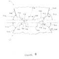
- Figure 9 illustrates a third embodiment of the workpiece of the present disclosure.
- the workpiece of Figure 9 has the same double pyramidal cross-sectional geometry as has been described above in relation to the second embodiment of the workpiece.
- the embodiment of Figure 9 differs from the embodiment of Figure 8 only in respect of the first and second pyramidal angles 132A,142A.
- the first pyramidal angle 132A is equal to the second pyramidal angle 142A, and each subtends an angle of 25° relative to the central ridge surface 120A.
- the third and fourth pyramidal surfaces prevent the generation of material deformation and detachment at the weld interface by providing additional lateral support to the edges of the weld interface. This additional mechanical support prevents the material ejected from the weld interface from deforming and detaching from the weld stub.
- first and second materials have different hardness values to one another it is necessary to provide the first workpiece 100 with a different value for the third and fourth pyramidal angle to that of the second workpiece 102.
- the determination of the third and fourth pyramidal angles 152A,152B;162A,162B for each of the first and second workpieces 100,102 can be determined from the relative upset between the first and second workpieces 100,102. In other words, by knowing the upset behaviour of each of the first and second materials, for example for a standard geometry it is possible to determine the magnitudes the third and fourth pyramidal angles 152A,152B;162A,162B for each of the first and second workpieces 100,102.
- the third and fourth pyramidal angles 152A;162A for the first workpiece 100 will be greater (i.e. closer to 90°) than the corresponding third and fourth pyramidal angles 152B; 162B for the second workpiece 102.
- first and second workpiece 100,102 are formed from materials having different hardness
- the workpiece geometry of the present disclosure may equally be applied to situations in which the first workpiece 100 and the second workpiece 102 are formed from materials having the same hardness.
- the first workpiece and the second workpiece may each be formed from a titanium alloy.
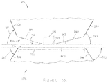
- Figures 10 and 11 respectively show fourth and fifth embodiments of the present disclosure in which the first workpiece 200,300 and the second workpiece 202,302 are formed from materials having the same hardness.
- Figure 10 illustrates a fourth embodiment of the present disclosure, in which a first workpiece 200 is formed from a first material, and a second workpiece 201 is formed from a second material, with the first and second materials having the same hardness.
- the first workpiece 200 comprises a central ridge surface 220 having a lateral width 222 that is flanked on either side by a first pyramidal surface 230 and a second pyramidal surface 240.
- the first pyramidal surface 230 subtends a first pyramidal angle 232 with the central ridge surface 220
- the second pyramidal surface 240 subtends a second pyramidal angle 242 with the central ridge surface 220.
- each of the first pyramidal angle 232 and the second pyramidal angle 242 is 10°.
- the first pyramidal surface 230 is further flanked by a third pyramidal surface 250 on a distal side of the first pyramidal surface 230 from the central ridge surface 220.
- the second pyramidal surface 240 is further flanked by a fourth pyramidal surface 260 on a distal side of the second pyramidal surface 240 from the central ridge surface 220.
- the third pyramidal surface 250 subtends a third pyramidal angle 252 with the central ridge surface 220.
- the fourth pyramidal surface 260 subtends a fourth pyramidal angle 262 with the central ridge surface 220.
- the third pyramidal angle 252 is equal to the fourth pyramidal angle 262, and each subtends an angle of 40° relative to the central ridge surface 220.
- the second workpiece 202 comprises a central surface 224 having a lateral width 226 of approximately 24 mm, flanked on either side respectively by a first flank surface 234 and a second flank surface 236.
- Each of the first flank surface 234 and the second flank surface 244 subtends a corresponding first flank angle 235 and second flank angle 245 relative to the central surface 224.
- the first flank angle 234 is equal to the second flank angle 245 and has a value of 40°.
- Figure 11 illustrates a fifth embodiment of the present disclosure, in which a first workpiece 300 is formed from a first material, and a second workpiece 301 is formed from a second material, with the first and second materials having the same hardness.
- the first workpiece 300 comprises a central ridge surface 320 having a lateral width 322 that is flanked on either side by a first pyramidal surface 330 and a second pyramidal surface 340.
- the first pyramidal surface 330 subtends a first pyramidal angle 332 with the central ridge surface 320
- the second pyramidal surface 340 subtends a second pyramidal angle 342 with the central ridge surface 320.
- each of the first pyramidal angle 332 and the second pyramidal angle 342 is 10°.
- the first pyramidal surface 330 is further flanked by a first side surface 350 on a distal side of the first pyramidal surface 330 from the central ridge surface 320.
- the second pyramidal surface 340 is further flanked by a second surface 360 on a distal side of the second pyramidal surface 340 from the central ridge surface 320.
- Each of the first side surface 350 and the second side surface 360 is oriented at 90° to (i.e. normal to) the central ridge surface 320.
- the second workpiece 302 comprises a central surface 324 having a lateral width 326 of approximately 24 mm, flanked on either side respectively by a first flank surface 334 and a second flank surface 336.
- Each of the first flank surface 334 and the second flank surface 344 subtends a corresponding first flank angle 335 and second flank angle 345 relative to the central surface 324.
- the first flank angle 334 is equal to the second flank angle 345 and has a value of 40°.
- FIG. 7 illustrates an example of such an application in which a rotor 400 is joined with a rotor blade 410.
- a plurality of fan rotor blades 410 may then be joined to the rotor 400 to thereby form a bladed fan disk 402.
- a plurality of compressor blades 412 may be joined to a compressor drum 406 to form a compressor disk 404.
Landscapes
- Engineering & Computer Science (AREA)
- Mechanical Engineering (AREA)
- Pressure Welding/Diffusion-Bonding (AREA)
Applications Claiming Priority (1)
| Application Number | Priority Date | Filing Date | Title |
|---|---|---|---|
| GB1614566.6A GB2553146A (en) | 2016-08-26 | 2016-08-26 | A friction welding process |
Publications (3)
| Publication Number | Publication Date |
|---|---|
| EP3287226A2 true EP3287226A2 (de) | 2018-02-28 |
| EP3287226A3 EP3287226A3 (de) | 2018-03-28 |
| EP3287226B1 EP3287226B1 (de) | 2020-04-22 |
Family
ID=57119886
Family Applications (1)
| Application Number | Title | Priority Date | Filing Date |
|---|---|---|---|
| EP17187703.8A Active EP3287226B1 (de) | 2016-08-26 | 2017-08-24 | Linear reibschweissverfahren von werkstücken |
Country Status (5)
| Country | Link |
|---|---|
| US (2) | US20180056437A1 (de) |
| EP (1) | EP3287226B1 (de) |
| JP (1) | JP2018030175A (de) |
| CN (1) | CN107775184A (de) |
| GB (1) | GB2553146A (de) |
Cited By (1)
| Publication number | Priority date | Publication date | Assignee | Title |
|---|---|---|---|---|
| EP3581317A1 (de) * | 2018-06-11 | 2019-12-18 | Rolls-Royce plc | Ein verfahren zum linearen reibschweissen |
Families Citing this family (4)
| Publication number | Priority date | Publication date | Assignee | Title |
|---|---|---|---|---|
| GB2560001B (en) * | 2017-02-24 | 2019-07-17 | Rolls Royce Plc | A weld stub arrangement and a method of using the arrangement to make an article |
| JP6681941B2 (ja) * | 2018-05-31 | 2020-04-15 | 株式会社Uacj | 衝撃吸収部材 |
| CN111112822A (zh) * | 2020-01-03 | 2020-05-08 | 中国航空制造技术研究院 | 一种线性摩擦焊接方法 |
| BE1031526B1 (fr) * | 2023-04-21 | 2024-11-18 | Safran Aero Boosters | Procédé de soudage par friction orbitale d'une aube à un moignon sur un disque rotorique de turbomachine |
Family Cites Families (22)
| Publication number | Priority date | Publication date | Assignee | Title |
|---|---|---|---|---|
| US1555081A (en) * | 1923-04-27 | 1925-09-29 | Warren Webster & Co | Steam and vent trap apparatus |
| GB416365A (en) * | 1934-02-06 | 1934-09-12 | Meaf Mach En Apparaten Fab Nv | Improvements in electric arc welding |
| GB9011605D0 (en) * | 1990-05-24 | 1990-07-11 | Rolls Royce Plc | Friction bonding |
| DE69404738T2 (de) * | 1993-05-13 | 1998-02-19 | Rolls Royce Plc | Reibschweissen |
| US5813593A (en) * | 1996-11-15 | 1998-09-29 | General Electric Company | Translational friction welding apparatus and method |
| US6219916B1 (en) * | 1997-12-19 | 2001-04-24 | United Technologies Corporation | Method for linear friction welding and product made by such method |
| US6478545B2 (en) * | 2001-03-07 | 2002-11-12 | General Electric Company | Fluted blisk |
| GB0400821D0 (en) * | 2004-01-15 | 2004-02-18 | Rolls Royce Plc | Friction welding process |
| DE102004032975A1 (de) * | 2004-07-08 | 2006-02-09 | Mtu Aero Engines Gmbh | Verfahren zum Verbinden von Schaufelblättern mit Schaufelfüßen oder Rotorscheiben bei der Herstellung und/oder Reparatur von Gasturbinenschaufeln oder integral beschaufelten Gasturbinenrotoren |
| GB0512184D0 (en) * | 2005-06-15 | 2005-07-20 | Rolls Royce Plc | Method and apparatus for the treatment of a component |
| GB0615671D0 (en) * | 2006-08-08 | 2006-09-13 | Rolls Royce Plc | A method of friction welding |
| DE102007050142A1 (de) * | 2007-10-19 | 2009-04-23 | Mtu Aero Engines Gmbh | Verfahren zur Herstellung einer Blisk oder eines Blings, damit hergestelltes Bauteil und Turbinenschaufel |
| GB0906869D0 (en) * | 2009-04-22 | 2009-06-03 | Rolls Royce Plc | Developments in or relating to linear friction welding |
| FR2992880B1 (fr) * | 2012-07-06 | 2015-02-13 | Snecma | Piece pour soudage par friction |
| US20140140859A1 (en) * | 2012-09-28 | 2014-05-22 | United Technologies Corporation | Uber-cooled multi-alloy integrally bladed rotor |
| US9303589B2 (en) * | 2012-11-28 | 2016-04-05 | Pratt & Whitney Canada Corp. | Low hub-to-tip ratio fan for a turbofan gas turbine engine |
| US8651361B1 (en) * | 2013-02-13 | 2014-02-18 | The Boeing Company | Method for angular oscillation friction welding to an axially symmetric weld surface |
| GB201413923D0 (en) * | 2014-08-06 | 2014-09-17 | Rolls Royce Plc | Rotary friction welding |
| US9951632B2 (en) * | 2015-07-23 | 2018-04-24 | Honeywell International Inc. | Hybrid bonded turbine rotors and methods for manufacturing the same |
| GB2560001B (en) * | 2017-02-24 | 2019-07-17 | Rolls Royce Plc | A weld stub arrangement and a method of using the arrangement to make an article |
| US10605101B2 (en) * | 2017-09-12 | 2020-03-31 | United Technologies Corporation | Process of making integrally bladed rotor |
| US10792771B2 (en) * | 2017-09-12 | 2020-10-06 | Raytheon Technologies Corporation | Method of making integrally bladed rotor |
-
2016
- 2016-08-26 GB GB1614566.6A patent/GB2553146A/en not_active Withdrawn
-
2017
- 2017-08-24 EP EP17187703.8A patent/EP3287226B1/de active Active
- 2017-08-24 US US15/685,081 patent/US20180056437A1/en not_active Abandoned
- 2017-08-25 JP JP2017162225A patent/JP2018030175A/ja not_active Withdrawn
- 2017-08-28 CN CN201710749971.XA patent/CN107775184A/zh active Pending
-
2019
- 2019-01-18 US US16/252,136 patent/US20190168336A1/en not_active Abandoned
Cited By (2)
| Publication number | Priority date | Publication date | Assignee | Title |
|---|---|---|---|---|
| EP3581317A1 (de) * | 2018-06-11 | 2019-12-18 | Rolls-Royce plc | Ein verfahren zum linearen reibschweissen |
| US11072037B2 (en) | 2018-06-11 | 2021-07-27 | Rolls-Royce Plc | Method of friction welding workpieces by adjusting a sweep length |
Also Published As
| Publication number | Publication date |
|---|---|
| EP3287226A3 (de) | 2018-03-28 |
| GB201614566D0 (en) | 2016-10-12 |
| US20180056437A1 (en) | 2018-03-01 |
| CN107775184A (zh) | 2018-03-09 |
| JP2018030175A (ja) | 2018-03-01 |
| US20190168336A1 (en) | 2019-06-06 |
| GB2553146A (en) | 2018-02-28 |
| EP3287226B1 (de) | 2020-04-22 |
Similar Documents
| Publication | Publication Date | Title |
|---|---|---|
| US20190168336A1 (en) | Friction welding process | |
| CN101952078B (zh) | 摩擦塞焊方法及系统 | |
| US9919356B2 (en) | Punch-riveting die | |
| JP5804038B2 (ja) | 接合方法 | |
| CN110685981B (zh) | 板材彼此的接合结构 | |
| EP1439314B1 (de) | Ermüdungsbeständige Schlitz- und Laschenkomponente, Schlitz- und Laschenverschweisselement und Verfahren zu seinem Verbinden | |
| EP2409807A2 (de) | Lineares Reibschweißen eines Blisk | |
| JP6104427B2 (ja) | 異材接合体 | |
| EP3581317B1 (de) | Ein verfahren zum linearen reibschweissen | |
| CN110023640B (zh) | 垫圈的制造方法和垫圈 | |
| JP7557676B2 (ja) | 接合構造 | |
| JP5092333B2 (ja) | 接合方法 | |
| CN111819026A (zh) | 接合结构以及接合方法 | |
| JP6975917B2 (ja) | 接合構造体 | |
| JP6984418B2 (ja) | ブリスクの製作方法及び装置 | |
| JP2012071353A (ja) | 接合方法 | |
| CN112004636A (zh) | 具有用于增加接合强度的设计间隙的搭接焊 | |
| JP2016052666A (ja) | 接合構造体およびその製造方法、ならびに冷却器 | |
| JP4844329B2 (ja) | 接合方法 | |
| JP5082364B2 (ja) | 接合方法 | |
| CN111868865B (zh) | 接触件及接触件的制造方法 | |
| JP7385194B2 (ja) | 異種材接合方法および複合部材 | |
| JP2009014213A (ja) | クラッド部材の剪断面被覆工法 | |
| JP4935282B2 (ja) | 摩擦攪拌方法 | |
| JP2001198634A (ja) | バーリングパンチ |
Legal Events
| Date | Code | Title | Description |
|---|---|---|---|
| PUAI | Public reference made under article 153(3) epc to a published international application that has entered the european phase |
Free format text: ORIGINAL CODE: 0009012 |
|
| STAA | Information on the status of an ep patent application or granted ep patent |
Free format text: STATUS: THE APPLICATION HAS BEEN PUBLISHED |
|
| PUAL | Search report despatched |
Free format text: ORIGINAL CODE: 0009013 |
|
| AK | Designated contracting states |
Kind code of ref document: A2 Designated state(s): AL AT BE BG CH CY CZ DE DK EE ES FI FR GB GR HR HU IE IS IT LI LT LU LV MC MK MT NL NO PL PT RO RS SE SI SK SM TR |
|
| AX | Request for extension of the european patent |
Extension state: BA ME |
|
| AK | Designated contracting states |
Kind code of ref document: A3 Designated state(s): AL AT BE BG CH CY CZ DE DK EE ES FI FR GB GR HR HU IE IS IT LI LT LU LV MC MK MT NL NO PL PT RO RS SE SI SK SM TR |
|
| AX | Request for extension of the european patent |
Extension state: BA ME |
|
| RIC1 | Information provided on ipc code assigned before grant |
Ipc: B23K 33/00 20060101ALI20180222BHEP Ipc: B23K 103/18 20060101ALN20180222BHEP Ipc: B23K 101/00 20060101ALN20180222BHEP Ipc: B23K 20/12 20060101AFI20180222BHEP |
|
| STAA | Information on the status of an ep patent application or granted ep patent |
Free format text: STATUS: REQUEST FOR EXAMINATION WAS MADE |
|
| 17P | Request for examination filed |
Effective date: 20180928 |
|
| RBV | Designated contracting states (corrected) |
Designated state(s): AL AT BE BG CH CY CZ DE DK EE ES FI FR GB GR HR HU IE IS IT LI LT LU LV MC MK MT NL NO PL PT RO RS SE SI SK SM TR |
|
| STAA | Information on the status of an ep patent application or granted ep patent |
Free format text: STATUS: EXAMINATION IS IN PROGRESS |
|
| 17Q | First examination report despatched |
Effective date: 20190228 |
|
| RIC1 | Information provided on ipc code assigned before grant |
Ipc: B23K 33/00 20060101ALI20191108BHEP Ipc: B23K 101/00 20060101ALN20191108BHEP Ipc: B23K 20/12 20060101AFI20191108BHEP Ipc: B23K 103/18 20060101ALN20191108BHEP |
|
| RIC1 | Information provided on ipc code assigned before grant |
Ipc: B23K 103/18 20060101ALN20191127BHEP Ipc: B23K 101/00 20060101ALN20191127BHEP Ipc: B23K 33/00 20060101ALI20191127BHEP Ipc: B23K 20/12 20060101AFI20191127BHEP |
|
| GRAP | Despatch of communication of intention to grant a patent |
Free format text: ORIGINAL CODE: EPIDOSNIGR1 |
|
| STAA | Information on the status of an ep patent application or granted ep patent |
Free format text: STATUS: GRANT OF PATENT IS INTENDED |
|
| RIC1 | Information provided on ipc code assigned before grant |
Ipc: B23K 103/18 20060101ALN20191209BHEP Ipc: B23K 20/12 20060101AFI20191209BHEP Ipc: B23K 101/00 20060101ALN20191209BHEP Ipc: B23K 33/00 20060101ALI20191209BHEP |
|
| GRAJ | Information related to disapproval of communication of intention to grant by the applicant or resumption of examination proceedings by the epo deleted |
Free format text: ORIGINAL CODE: EPIDOSDIGR1 |
|
| INTG | Intention to grant announced |
Effective date: 20200107 |
|
| STAA | Information on the status of an ep patent application or granted ep patent |
Free format text: STATUS: EXAMINATION IS IN PROGRESS |
|
| GRAP | Despatch of communication of intention to grant a patent |
Free format text: ORIGINAL CODE: EPIDOSNIGR1 |
|
| STAA | Information on the status of an ep patent application or granted ep patent |
Free format text: STATUS: GRANT OF PATENT IS INTENDED |
|
| INTC | Intention to grant announced (deleted) | ||
| RAP1 | Party data changed (applicant data changed or rights of an application transferred) |
Owner name: ROLLS-ROYCE PLC |
|
| RIC1 | Information provided on ipc code assigned before grant |
Ipc: B23K 20/12 20060101AFI20200122BHEP Ipc: B23K 33/00 20060101ALI20200122BHEP Ipc: B23K 101/00 20060101ALN20200122BHEP Ipc: B23K 103/18 20060101ALN20200122BHEP |
|
| GRAS | Grant fee paid |
Free format text: ORIGINAL CODE: EPIDOSNIGR3 |
|
| GRAA | (expected) grant |
Free format text: ORIGINAL CODE: 0009210 |
|
| STAA | Information on the status of an ep patent application or granted ep patent |
Free format text: STATUS: THE PATENT HAS BEEN GRANTED |
|
| INTG | Intention to grant announced |
Effective date: 20200226 |
|
| AK | Designated contracting states |
Kind code of ref document: B1 Designated state(s): AL AT BE BG CH CY CZ DE DK EE ES FI FR GB GR HR HU IE IS IT LI LT LU LV MC MK MT NL NO PL PT RO RS SE SI SK SM TR |
|
| REG | Reference to a national code |
Ref country code: CH Ref legal event code: EP |
|
| REG | Reference to a national code |
Ref country code: IE Ref legal event code: FG4D |
|
| REG | Reference to a national code |
Ref country code: DE Ref legal event code: R096 Ref document number: 602017015079 Country of ref document: DE |
|
| REG | Reference to a national code |
Ref country code: AT Ref legal event code: REF Ref document number: 1259433 Country of ref document: AT Kind code of ref document: T Effective date: 20200515 |
|
| REG | Reference to a national code |
Ref country code: LT Ref legal event code: MG4D |
|
| REG | Reference to a national code |
Ref country code: NL Ref legal event code: MP Effective date: 20200422 |
|
| PG25 | Lapsed in a contracting state [announced via postgrant information from national office to epo] |
Ref country code: FI Free format text: LAPSE BECAUSE OF FAILURE TO SUBMIT A TRANSLATION OF THE DESCRIPTION OR TO PAY THE FEE WITHIN THE PRESCRIBED TIME-LIMIT Effective date: 20200422 Ref country code: LT Free format text: LAPSE BECAUSE OF FAILURE TO SUBMIT A TRANSLATION OF THE DESCRIPTION OR TO PAY THE FEE WITHIN THE PRESCRIBED TIME-LIMIT Effective date: 20200422 Ref country code: GR Free format text: LAPSE BECAUSE OF FAILURE TO SUBMIT A TRANSLATION OF THE DESCRIPTION OR TO PAY THE FEE WITHIN THE PRESCRIBED TIME-LIMIT Effective date: 20200723 Ref country code: IS Free format text: LAPSE BECAUSE OF FAILURE TO SUBMIT A TRANSLATION OF THE DESCRIPTION OR TO PAY THE FEE WITHIN THE PRESCRIBED TIME-LIMIT Effective date: 20200822 Ref country code: NO Free format text: LAPSE BECAUSE OF FAILURE TO SUBMIT A TRANSLATION OF THE DESCRIPTION OR TO PAY THE FEE WITHIN THE PRESCRIBED TIME-LIMIT Effective date: 20200722 Ref country code: SE Free format text: LAPSE BECAUSE OF FAILURE TO SUBMIT A TRANSLATION OF THE DESCRIPTION OR TO PAY THE FEE WITHIN THE PRESCRIBED TIME-LIMIT Effective date: 20200422 Ref country code: NL Free format text: LAPSE BECAUSE OF FAILURE TO SUBMIT A TRANSLATION OF THE DESCRIPTION OR TO PAY THE FEE WITHIN THE PRESCRIBED TIME-LIMIT Effective date: 20200422 Ref country code: PT Free format text: LAPSE BECAUSE OF FAILURE TO SUBMIT A TRANSLATION OF THE DESCRIPTION OR TO PAY THE FEE WITHIN THE PRESCRIBED TIME-LIMIT Effective date: 20200824 |
|
| PGFP | Annual fee paid to national office [announced via postgrant information from national office to epo] |
Ref country code: FR Payment date: 20200824 Year of fee payment: 4 |
|
| REG | Reference to a national code |
Ref country code: AT Ref legal event code: MK05 Ref document number: 1259433 Country of ref document: AT Kind code of ref document: T Effective date: 20200422 |
|
| PG25 | Lapsed in a contracting state [announced via postgrant information from national office to epo] |
Ref country code: HR Free format text: LAPSE BECAUSE OF FAILURE TO SUBMIT A TRANSLATION OF THE DESCRIPTION OR TO PAY THE FEE WITHIN THE PRESCRIBED TIME-LIMIT Effective date: 20200422 Ref country code: RS Free format text: LAPSE BECAUSE OF FAILURE TO SUBMIT A TRANSLATION OF THE DESCRIPTION OR TO PAY THE FEE WITHIN THE PRESCRIBED TIME-LIMIT Effective date: 20200422 Ref country code: BG Free format text: LAPSE BECAUSE OF FAILURE TO SUBMIT A TRANSLATION OF THE DESCRIPTION OR TO PAY THE FEE WITHIN THE PRESCRIBED TIME-LIMIT Effective date: 20200722 Ref country code: LV Free format text: LAPSE BECAUSE OF FAILURE TO SUBMIT A TRANSLATION OF THE DESCRIPTION OR TO PAY THE FEE WITHIN THE PRESCRIBED TIME-LIMIT Effective date: 20200422 |
|
| PG25 | Lapsed in a contracting state [announced via postgrant information from national office to epo] |
Ref country code: AL Free format text: LAPSE BECAUSE OF FAILURE TO SUBMIT A TRANSLATION OF THE DESCRIPTION OR TO PAY THE FEE WITHIN THE PRESCRIBED TIME-LIMIT Effective date: 20200422 |
|
| REG | Reference to a national code |
Ref country code: DE Ref legal event code: R097 Ref document number: 602017015079 Country of ref document: DE |
|
| PG25 | Lapsed in a contracting state [announced via postgrant information from national office to epo] |
Ref country code: IT Free format text: LAPSE BECAUSE OF FAILURE TO SUBMIT A TRANSLATION OF THE DESCRIPTION OR TO PAY THE FEE WITHIN THE PRESCRIBED TIME-LIMIT Effective date: 20200422 Ref country code: DK Free format text: LAPSE BECAUSE OF FAILURE TO SUBMIT A TRANSLATION OF THE DESCRIPTION OR TO PAY THE FEE WITHIN THE PRESCRIBED TIME-LIMIT Effective date: 20200422 Ref country code: EE Free format text: LAPSE BECAUSE OF FAILURE TO SUBMIT A TRANSLATION OF THE DESCRIPTION OR TO PAY THE FEE WITHIN THE PRESCRIBED TIME-LIMIT Effective date: 20200422 Ref country code: SM Free format text: LAPSE BECAUSE OF FAILURE TO SUBMIT A TRANSLATION OF THE DESCRIPTION OR TO PAY THE FEE WITHIN THE PRESCRIBED TIME-LIMIT Effective date: 20200422 Ref country code: AT Free format text: LAPSE BECAUSE OF FAILURE TO SUBMIT A TRANSLATION OF THE DESCRIPTION OR TO PAY THE FEE WITHIN THE PRESCRIBED TIME-LIMIT Effective date: 20200422 Ref country code: RO Free format text: LAPSE BECAUSE OF FAILURE TO SUBMIT A TRANSLATION OF THE DESCRIPTION OR TO PAY THE FEE WITHIN THE PRESCRIBED TIME-LIMIT Effective date: 20200422 Ref country code: ES Free format text: LAPSE BECAUSE OF FAILURE TO SUBMIT A TRANSLATION OF THE DESCRIPTION OR TO PAY THE FEE WITHIN THE PRESCRIBED TIME-LIMIT Effective date: 20200422 Ref country code: CZ Free format text: LAPSE BECAUSE OF FAILURE TO SUBMIT A TRANSLATION OF THE DESCRIPTION OR TO PAY THE FEE WITHIN THE PRESCRIBED TIME-LIMIT Effective date: 20200422 |
|
| PGFP | Annual fee paid to national office [announced via postgrant information from national office to epo] |
Ref country code: DE Payment date: 20201029 Year of fee payment: 4 |
|
| PG25 | Lapsed in a contracting state [announced via postgrant information from national office to epo] |
Ref country code: PL Free format text: LAPSE BECAUSE OF FAILURE TO SUBMIT A TRANSLATION OF THE DESCRIPTION OR TO PAY THE FEE WITHIN THE PRESCRIBED TIME-LIMIT Effective date: 20200422 Ref country code: SK Free format text: LAPSE BECAUSE OF FAILURE TO SUBMIT A TRANSLATION OF THE DESCRIPTION OR TO PAY THE FEE WITHIN THE PRESCRIBED TIME-LIMIT Effective date: 20200422 |
|
| PLBE | No opposition filed within time limit |
Free format text: ORIGINAL CODE: 0009261 |
|
| STAA | Information on the status of an ep patent application or granted ep patent |
Free format text: STATUS: NO OPPOSITION FILED WITHIN TIME LIMIT |
|
| 26N | No opposition filed |
Effective date: 20210125 |
|
| PG25 | Lapsed in a contracting state [announced via postgrant information from national office to epo] |
Ref country code: MC Free format text: LAPSE BECAUSE OF FAILURE TO SUBMIT A TRANSLATION OF THE DESCRIPTION OR TO PAY THE FEE WITHIN THE PRESCRIBED TIME-LIMIT Effective date: 20200422 |
|
| REG | Reference to a national code |
Ref country code: CH Ref legal event code: PL |
|
| PG25 | Lapsed in a contracting state [announced via postgrant information from national office to epo] |
Ref country code: CH Free format text: LAPSE BECAUSE OF NON-PAYMENT OF DUE FEES Effective date: 20200831 Ref country code: LU Free format text: LAPSE BECAUSE OF NON-PAYMENT OF DUE FEES Effective date: 20200824 Ref country code: LI Free format text: LAPSE BECAUSE OF NON-PAYMENT OF DUE FEES Effective date: 20200831 |
|
| REG | Reference to a national code |
Ref country code: BE Ref legal event code: MM Effective date: 20200831 |
|
| PG25 | Lapsed in a contracting state [announced via postgrant information from national office to epo] |
Ref country code: SI Free format text: LAPSE BECAUSE OF FAILURE TO SUBMIT A TRANSLATION OF THE DESCRIPTION OR TO PAY THE FEE WITHIN THE PRESCRIBED TIME-LIMIT Effective date: 20200422 |
|
| PG25 | Lapsed in a contracting state [announced via postgrant information from national office to epo] |
Ref country code: BE Free format text: LAPSE BECAUSE OF NON-PAYMENT OF DUE FEES Effective date: 20200831 Ref country code: IE Free format text: LAPSE BECAUSE OF NON-PAYMENT OF DUE FEES Effective date: 20200824 |
|
| REG | Reference to a national code |
Ref country code: DE Ref legal event code: R119 Ref document number: 602017015079 Country of ref document: DE |
|
| GBPC | Gb: european patent ceased through non-payment of renewal fee |
Effective date: 20210824 |
|
| PG25 | Lapsed in a contracting state [announced via postgrant information from national office to epo] |
Ref country code: TR Free format text: LAPSE BECAUSE OF FAILURE TO SUBMIT A TRANSLATION OF THE DESCRIPTION OR TO PAY THE FEE WITHIN THE PRESCRIBED TIME-LIMIT Effective date: 20200422 Ref country code: MT Free format text: LAPSE BECAUSE OF FAILURE TO SUBMIT A TRANSLATION OF THE DESCRIPTION OR TO PAY THE FEE WITHIN THE PRESCRIBED TIME-LIMIT Effective date: 20200422 Ref country code: CY Free format text: LAPSE BECAUSE OF FAILURE TO SUBMIT A TRANSLATION OF THE DESCRIPTION OR TO PAY THE FEE WITHIN THE PRESCRIBED TIME-LIMIT Effective date: 20200422 |
|
| PG25 | Lapsed in a contracting state [announced via postgrant information from national office to epo] |
Ref country code: MK Free format text: LAPSE BECAUSE OF FAILURE TO SUBMIT A TRANSLATION OF THE DESCRIPTION OR TO PAY THE FEE WITHIN THE PRESCRIBED TIME-LIMIT Effective date: 20200422 |
|
| PG25 | Lapsed in a contracting state [announced via postgrant information from national office to epo] |
Ref country code: GB Free format text: LAPSE BECAUSE OF NON-PAYMENT OF DUE FEES Effective date: 20210824 Ref country code: FR Free format text: LAPSE BECAUSE OF NON-PAYMENT OF DUE FEES Effective date: 20210831 Ref country code: DE Free format text: LAPSE BECAUSE OF NON-PAYMENT OF DUE FEES Effective date: 20220301 |