EP3287228A1 - Dispositif de fabrication d'ensemble et procédé de fabrication d'ensemble - Google Patents
Dispositif de fabrication d'ensemble et procédé de fabrication d'ensemble Download PDFInfo
- Publication number
- EP3287228A1 EP3287228A1 EP16838951.8A EP16838951A EP3287228A1 EP 3287228 A1 EP3287228 A1 EP 3287228A1 EP 16838951 A EP16838951 A EP 16838951A EP 3287228 A1 EP3287228 A1 EP 3287228A1
- Authority
- EP
- European Patent Office
- Prior art keywords
- gripping
- long member
- parts
- gripping parts
- robot
- Prior art date
- Legal status (The legal status is an assumption and is not a legal conclusion. Google has not performed a legal analysis and makes no representation as to the accuracy of the status listed.)
- Withdrawn
Links
Images



Classifications
-
- B—PERFORMING OPERATIONS; TRANSPORTING
- B25—HAND TOOLS; PORTABLE POWER-DRIVEN TOOLS; MANIPULATORS
- B25J—MANIPULATORS; CHAMBERS PROVIDED WITH MANIPULATION DEVICES
- B25J13/00—Controls for manipulators
- B25J13/02—Hand grip control means
-
- B—PERFORMING OPERATIONS; TRANSPORTING
- B23—MACHINE TOOLS; METAL-WORKING NOT OTHERWISE PROVIDED FOR
- B23P—METAL-WORKING NOT OTHERWISE PROVIDED FOR; COMBINED OPERATIONS; UNIVERSAL MACHINE TOOLS
- B23P19/00—Machines for simply fitting together or separating metal parts or objects, or metal and non-metal parts, whether or not involving some deformation; Tools or devices therefor so far as not provided for in other classes
- B23P19/04—Machines for simply fitting together or separating metal parts or objects, or metal and non-metal parts, whether or not involving some deformation; Tools or devices therefor so far as not provided for in other classes for assembling or disassembling parts
-
- B—PERFORMING OPERATIONS; TRANSPORTING
- B21—MECHANICAL METAL-WORKING WITHOUT ESSENTIALLY REMOVING MATERIAL; PUNCHING METAL
- B21J—FORGING; HAMMERING; PRESSING METAL; RIVETING; FORGE FURNACES
- B21J15/00—Riveting
- B21J15/10—Riveting machines
- B21J15/14—Riveting machines specially adapted for riveting specific articles, e.g. brake lining machines
- B21J15/142—Aerospace structures
-
- B—PERFORMING OPERATIONS; TRANSPORTING
- B21—MECHANICAL METAL-WORKING WITHOUT ESSENTIALLY REMOVING MATERIAL; PUNCHING METAL
- B21J—FORGING; HAMMERING; PRESSING METAL; RIVETING; FORGE FURNACES
- B21J15/00—Riveting
- B21J15/38—Accessories for use in connection with riveting, e.g. pliers for upsetting; Hand tools for riveting
- B21J15/42—Special clamping devices for workpieces to be riveted together, e.g. operating through the rivet holes
-
- B—PERFORMING OPERATIONS; TRANSPORTING
- B23—MACHINE TOOLS; METAL-WORKING NOT OTHERWISE PROVIDED FOR
- B23P—METAL-WORKING NOT OTHERWISE PROVIDED FOR; COMBINED OPERATIONS; UNIVERSAL MACHINE TOOLS
- B23P19/00—Machines for simply fitting together or separating metal parts or objects, or metal and non-metal parts, whether or not involving some deformation; Tools or devices therefor so far as not provided for in other classes
- B23P19/10—Aligning parts to be fitted together
-
- B—PERFORMING OPERATIONS; TRANSPORTING
- B25—HAND TOOLS; PORTABLE POWER-DRIVEN TOOLS; MANIPULATORS
- B25J—MANIPULATORS; CHAMBERS PROVIDED WITH MANIPULATION DEVICES
- B25J13/00—Controls for manipulators
-
- B—PERFORMING OPERATIONS; TRANSPORTING
- B25—HAND TOOLS; PORTABLE POWER-DRIVEN TOOLS; MANIPULATORS
- B25J—MANIPULATORS; CHAMBERS PROVIDED WITH MANIPULATION DEVICES
- B25J13/00—Controls for manipulators
- B25J13/08—Controls for manipulators by means of sensing devices, e.g. viewing or touching devices
- B25J13/088—Controls for manipulators by means of sensing devices, e.g. viewing or touching devices with position, velocity or acceleration sensors
- B25J13/089—Determining the position of the robot with reference to its environment
-
- B—PERFORMING OPERATIONS; TRANSPORTING
- B25—HAND TOOLS; PORTABLE POWER-DRIVEN TOOLS; MANIPULATORS
- B25J—MANIPULATORS; CHAMBERS PROVIDED WITH MANIPULATION DEVICES
- B25J15/00—Gripping heads and other end effectors
-
- B—PERFORMING OPERATIONS; TRANSPORTING
- B25—HAND TOOLS; PORTABLE POWER-DRIVEN TOOLS; MANIPULATORS
- B25J—MANIPULATORS; CHAMBERS PROVIDED WITH MANIPULATION DEVICES
- B25J9/00—Program-controlled manipulators
- B25J9/0084—Program-controlled manipulators comprising a plurality of manipulators
-
- B—PERFORMING OPERATIONS; TRANSPORTING
- B25—HAND TOOLS; PORTABLE POWER-DRIVEN TOOLS; MANIPULATORS
- B25J—MANIPULATORS; CHAMBERS PROVIDED WITH MANIPULATION DEVICES
- B25J9/00—Program-controlled manipulators
- B25J9/16—Program controls
- B25J9/1612—Program controls characterised by the hand, wrist, grip control
-
- B—PERFORMING OPERATIONS; TRANSPORTING
- B25—HAND TOOLS; PORTABLE POWER-DRIVEN TOOLS; MANIPULATORS
- B25J—MANIPULATORS; CHAMBERS PROVIDED WITH MANIPULATION DEVICES
- B25J9/00—Program-controlled manipulators
- B25J9/16—Program controls
- B25J9/1656—Program controls characterised by programming, planning systems for manipulators
- B25J9/1669—Program controls characterised by programming, planning systems for manipulators characterised by special application, e.g. multi-arm co-operation, assembly, grasping
-
- B—PERFORMING OPERATIONS; TRANSPORTING
- B25—HAND TOOLS; PORTABLE POWER-DRIVEN TOOLS; MANIPULATORS
- B25J—MANIPULATORS; CHAMBERS PROVIDED WITH MANIPULATION DEVICES
- B25J9/00—Program-controlled manipulators
- B25J9/16—Program controls
- B25J9/1679—Program controls characterised by the tasks executed
- B25J9/1682—Dual arm manipulator; Coordination of several manipulators
-
- B—PERFORMING OPERATIONS; TRANSPORTING
- B64—AIRCRAFT; AVIATION; COSMONAUTICS
- B64F—GROUND OR AIRCRAFT-CARRIER-DECK INSTALLATIONS SPECIALLY ADAPTED FOR USE IN CONNECTION WITH AIRCRAFT; DESIGNING, MANUFACTURING, ASSEMBLING, CLEANING, MAINTAINING OR REPAIRING AIRCRAFT, NOT OTHERWISE PROVIDED FOR; HANDLING, TRANSPORTING, TESTING OR INSPECTING AIRCRAFT COMPONENTS, NOT OTHERWISE PROVIDED FOR
- B64F5/00—Designing, manufacturing, assembling, cleaning, maintaining or repairing aircraft, not otherwise provided for; Handling, transporting, testing or inspecting aircraft components, not otherwise provided for
-
- B—PERFORMING OPERATIONS; TRANSPORTING
- B64—AIRCRAFT; AVIATION; COSMONAUTICS
- B64F—GROUND OR AIRCRAFT-CARRIER-DECK INSTALLATIONS SPECIALLY ADAPTED FOR USE IN CONNECTION WITH AIRCRAFT; DESIGNING, MANUFACTURING, ASSEMBLING, CLEANING, MAINTAINING OR REPAIRING AIRCRAFT, NOT OTHERWISE PROVIDED FOR; HANDLING, TRANSPORTING, TESTING OR INSPECTING AIRCRAFT COMPONENTS, NOT OTHERWISE PROVIDED FOR
- B64F5/00—Designing, manufacturing, assembling, cleaning, maintaining or repairing aircraft, not otherwise provided for; Handling, transporting, testing or inspecting aircraft components, not otherwise provided for
- B64F5/10—Manufacturing or assembling aircraft, e.g. jigs therefor
-
- B—PERFORMING OPERATIONS; TRANSPORTING
- B23—MACHINE TOOLS; METAL-WORKING NOT OTHERWISE PROVIDED FOR
- B23P—METAL-WORKING NOT OTHERWISE PROVIDED FOR; COMBINED OPERATIONS; UNIVERSAL MACHINE TOOLS
- B23P2700/00—Indexing scheme relating to the articles being treated, e.g. manufactured, repaired, assembled, connected or other operations covered in the subgroups
- B23P2700/01—Aircraft parts
-
- B—PERFORMING OPERATIONS; TRANSPORTING
- B25—HAND TOOLS; PORTABLE POWER-DRIVEN TOOLS; MANIPULATORS
- B25J—MANIPULATORS; CHAMBERS PROVIDED WITH MANIPULATION DEVICES
- B25J9/00—Program-controlled manipulators
- B25J9/16—Program controls
- B25J9/1679—Program controls characterised by the tasks executed
- B25J9/1687—Assembly, peg and hole, palletising, straight line, weaving pattern movement
-
- G—PHYSICS
- G05—CONTROLLING; REGULATING
- G05B—CONTROL OR REGULATING SYSTEMS IN GENERAL; FUNCTIONAL ELEMENTS OF SUCH SYSTEMS; MONITORING OR TESTING ARRANGEMENTS FOR SUCH SYSTEMS OR ELEMENTS
- G05B2219/00—Program-control systems
- G05B2219/30—Nc systems
- G05B2219/39—Robotics, robotics to robotics hand
- G05B2219/39123—Manipulate, handle flexible object
-
- G—PHYSICS
- G05—CONTROLLING; REGULATING
- G05B—CONTROL OR REGULATING SYSTEMS IN GENERAL; FUNCTIONAL ELEMENTS OF SUCH SYSTEMS; MONITORING OR TESTING ARRANGEMENTS FOR SUCH SYSTEMS OR ELEMENTS
- G05B2219/00—Program-control systems
- G05B2219/30—Nc systems
- G05B2219/39—Robotics, robotics to robotics hand
- G05B2219/39129—One manipulator holds one piece, other inserts, screws other piece, dexterity
-
- Y—GENERAL TAGGING OF NEW TECHNOLOGICAL DEVELOPMENTS; GENERAL TAGGING OF CROSS-SECTIONAL TECHNOLOGIES SPANNING OVER SEVERAL SECTIONS OF THE IPC; TECHNICAL SUBJECTS COVERED BY FORMER USPC CROSS-REFERENCE ART COLLECTIONS [XRACs] AND DIGESTS
- Y10—TECHNICAL SUBJECTS COVERED BY FORMER USPC
- Y10S—TECHNICAL SUBJECTS COVERED BY FORMER USPC CROSS-REFERENCE ART COLLECTIONS [XRACs] AND DIGESTS
- Y10S901/00—Robots
- Y10S901/02—Arm motion controller
- Y10S901/09—Closed loop, sensor feedback controls arm movement
-
- Y—GENERAL TAGGING OF NEW TECHNOLOGICAL DEVELOPMENTS; GENERAL TAGGING OF CROSS-SECTIONAL TECHNOLOGIES SPANNING OVER SEVERAL SECTIONS OF THE IPC; TECHNICAL SUBJECTS COVERED BY FORMER USPC CROSS-REFERENCE ART COLLECTIONS [XRACs] AND DIGESTS
- Y10—TECHNICAL SUBJECTS COVERED BY FORMER USPC
- Y10S—TECHNICAL SUBJECTS COVERED BY FORMER USPC CROSS-REFERENCE ART COLLECTIONS [XRACs] AND DIGESTS
- Y10S901/00—Robots
- Y10S901/30—End effector
-
- Y—GENERAL TAGGING OF NEW TECHNOLOGICAL DEVELOPMENTS; GENERAL TAGGING OF CROSS-SECTIONAL TECHNOLOGIES SPANNING OVER SEVERAL SECTIONS OF THE IPC; TECHNICAL SUBJECTS COVERED BY FORMER USPC CROSS-REFERENCE ART COLLECTIONS [XRACs] AND DIGESTS
- Y10—TECHNICAL SUBJECTS COVERED BY FORMER USPC
- Y10S—TECHNICAL SUBJECTS COVERED BY FORMER USPC CROSS-REFERENCE ART COLLECTIONS [XRACs] AND DIGESTS
- Y10S901/00—Robots
- Y10S901/46—Sensing device
- Y10S901/47—Optical
Definitions
- the present invention relates to an assembly body manufacturing device and an assembly body manufacturing method.
- a fixing jig has high rigidity and can thus prevent the long member from bending when the other component is mounted on the long member.
- Patent Document 1 describes technology related to a manufacturing environment such as an assembly line in which an article such as a wing used in the structure of an aircraft with a complicated shape that is difficult to support is moved while being held in a correct posture.
- Patent Document 1 JP-A-2015-42436
- the long member is, for example, a stringer, which is a structure of an aircraft, and has a length of approximately 5 m to 15 m.
- stringers have different shapes depending on the installation positions, and various types of stringers may be installed in one aircraft.
- fixing jigs for holding the stringers need to be prepared in mounting another component, such as clips, on the stringers.
- the stringers have stereoscopic shapes with compound curves. That is, the stringers are not linear members that can be installed along one plane, and the fixing jigs for holding the stringers also have complex shapes.
- an object of the present invention is to provide an assembly body manufacturing device and an assembly body manufacturing method capable of reducing positional deviation of a predetermined portion of the long member without using a fixing jig in holding the long member.
- An assembly body manufacturing device comprises:
- the plurality of first gripping parts grip the long first member
- the first drive part moves the plurality of first gripping parts gripping the first member and adjusts the position of each of the plurality of first gripping parts.
- the first member having a long shape is gripped by the second gripping part numbering less than the plurality of first gripping parts, and the second gripping part is moved and adjusted in position by the second drive part.
- the positional adjustment of the second gripping part by the second drive part has a higher positioning accuracy than that of the plurality of first gripping parts driven by the first drive part.
- the control unit drives the first drive part and the second drive part to adjust the positions of the plurality of first gripping parts and the second gripping part on the basis of the original shape of the first member stored in the storage unit.
- the first member gripped by the plurality of first gripping parts and the second gripping part is held in a shape matching the original shape of the first member stored in the storage unit by adjusting the positions of the gripping parts.
- the first member being held by the plurality of first gripping parts as well as the second gripping part with a higher positioning accuracy, compared to a case in which the second gripping part is not provided, positional deviation of the predetermined portion of the first member can be reduced.
- the first aspect preferably has a configuration wherein when positional adjustment is performed by the first drive part or the second drive part, the plurality of first gripping parts or the second gripping part allow the first member to move in a longitudinal direction while gripping the first member.
- the plurality of first gripping parts or the second gripping part are movable in the longitudinal direction of the first member while gripping the first member having a long shape and do not restrain movement or contraction/expansion in the longitudinal direction of the first member.
- the first aspect preferably has a configuration wherein gripping positions of the plurality of first gripping parts or the second gripping part are preliminarily determined on the basis of an original shape of the first member and an amount of deformation of the first member when the plurality of first gripping parts or the second gripping part grip the first member.
- the positions where the plurality of first gripping parts or the second gripping part grip the first member are preliminarily determined on the basis of the original shape of the first member and the amount of deformation of the first member when the plurality of first gripping parts or the second gripping part grip the first member, so that the plurality of first gripping parts or the second gripping part can grip the first member in such positions that the amount of deformation of the first member is minimized, for example.
- the first aspect preferably further comprises a plate-like fixing part configured to fix a first end of the first member and restrain movement of the first member in the longitudinal direction.
- the fixing part fixes the first end of the first member and restrains movement of the first member in the longitudinal direction, so that the first end of the first member can be set as a reference position for positioning.
- the first aspect preferably has a configuration wherein the fixing part is disposed on either end side of the plurality of first gripping parts arranged in a row.
- any of the fixing parts disposed on either side of the plurality of first gripping parts arranged in a row can be used, so that the fixing part can be selected depending on the shape and the like of the first member when the fixing part fixes the first end of the first member.
- the aspects of the present invention described above preferably have a configuration wherein a reference point used for adjusting the positions of the plurality of first gripping parts or the second gripping part is determined on the basis of positional information derived from an installation position of the fixing part.
- the reference point used for adjusting the positions of the plurality of first gripping parts or the second gripping part is determined precisely, so that the position of the first member can be adjusted precisely.
- the first aspect preferably has a configuration wherein a reference coordinate used for adjusting the positions of the plurality of first gripping parts or the second gripping part is determined on the basis of positional information derived from installation positions of two of the fixing parts.
- the reference coordinates used for adjusting the positions of the plurality of first gripping parts or the second gripping part is determined precisely, so that the position of the first member can be adjusted precisely.
- the first aspect preferably further comprises a mounting robot configured to mount a second member on the first member.
- the mounting robot mounts the second member on the first member gripped by the plurality of first gripping parts or the second gripping part.
- the first aspect preferably has a configuration wherein at least one of the plurality of first gripping parts, the second gripping part, and the mounting robot is movable and relatively changes a position thereof.
- At least one of the plurality of first gripping parts, the second gripping part, and the mounting robot moves to change a relative position thereof, so that the place where the mounting robot performs mounting can be different from, for example, the place where the plurality of first gripping parts take out the first member from a supplying position.
- An assembly body manufacturing method comprises the steps of:
- the second aspect preferably further comprising the steps of:
- the second aspect preferably further comprising the steps of:
- positional deviations of a predetermined portion of the long member can be reduced without using a fixing jig in holding the long member.
- the long member assembling device 1 includes a conveyor 2, a table 3, a plurality of supporting robots 4, touch plates 5, a mounting robot 6, a laser tracker 7, and a gripping robot 11.
- the long member assembling device 1 is an assembly body manufacturing device that manufactures an assembly body, the long member assembling device 1 having a configuration in which another component 22, which is a second member, is mounted on a long member 10, which is a first member.
- the long member assembling device 1 takes out the long member 10 from a supplying position 20 and conveys the long member 10 to a mounting position 21. Then, the other component 22 is mounted on the long member 10 in the mounting position 21. Before the component 22 is mounted, the long member 10 is temporarily placed in the supplying position 20, and the mounting robot 6 and the gripping robot 11 are placed in the vicinity of the mounting position 21 fixed on the floor.
- the long member 10 is, for example, a stringer which is a structural member of an aircraft.
- the stringer has a length of approximately 5 m to 15 m and has a stereoscopic shape with a compound curve, for example.
- Another component 22 called clip is mounted on the stringer.
- an object having a configuration in which the clip is mounted on the stringer corresponds to the assembly body.
- the clip is a component used in forming a long frame to which a plurality of the stringers are connected. When the frame is assembled together with the stringers, the clips mounted in precise positions in the longitudinal direction of the stringers enable the frame to be formed with the stringers connected thereto while the frame does not bend.
- a generally used conveyor can be used as the conveyor 2.
- the table 3, which will be described after, is placed on the conveyor 2.
- the conveyor 2 moves the table 3 from a first end side to a second end side and from the second end side to the first end side.
- the first end side of the conveyor 2 is located in the vicinity of the supplying position 20 for the long member 10, and the conveyor 2 moves the table 3 from the vicinity of the supplying position 20 to the vicinity of the mounting robot 6.
- the mounting robot 6 mounts one of the components 22 in a predetermined region of the long member 10, and then the conveyor 2 conveys the table 3 on which the supporting robots 4 gripping the long member 10 are installed.
- This operation allows the long member 10 to be conveyed while the supporting robots 4 grip the long member 10 while maintaining a component shape of the long member 10 in a predetermined held shape, and allows the mounting robot 6 to mount a component 22 in a next predetermined region.
- the conveyor 2 conveys the table 3, and the mounting robot 6 mounts a component 22 in a further next predetermined region of the long member 10. This operation is repeated to mount the components 22 on the entirety of the long member 10 in the longitudinal direction.
- a single component 22 may be mounted in a single predetermined region, or a plurality of the components 22 may be mounted in the longitudinal direction of the predetermined region.
- the supporting robots 4 and the touch plates 5 are installed in a row on the table 3. This configuration enables the supporting robots 4 and the touch plates 5 to integrally move on the conveyor 2.
- the supporting robots 4 are placed in a row on the table 3.
- the touch plates 5 are placed on both ends of the table 3, that is, both sides of the supporting robots 4.
- the number of the supporting robots 4 placed on the table 3 and the distance between the supporting robots 4 are preliminarily determined depending on the long member 10 to be assembled.
- the number of the supporting robots 4 to be operated for gripping the long member 10 is determined on the basis of the length of the long member 10 to be actually gripped.
- FIG. 1 illustrates a state in which four out of five supporting robots 4 are gripping the long member 10.
- the supporting robots 4 each include a hand part 8 that grips the long member 10, an arm part 9 provided with the hand part 8 at the leading end thereof, and a trunk part 12 supporting the arm part 9.
- the hand part 8 is exemplified as a first gripping part
- the arm part 9 and the trunk part 12 are exemplified as a first drive part.
- the hand part 8 includes a stopper 13 that grips the long member 10 to prevent the long member 10 from falling off, an A reference plane roller part 14 that determines a Y coordinate of the long member 10 so that the hand part 8 can move the long member 10 in an X direction when the stopper 13 does not grip the long member 10, and a B reference plane roller part 15 that determines a Z coordinate.
- a detailed configuration of the hand part 8 will be described below.
- the arm part 9 and the trunk part 12 move the hand part 8 so that the hand part 8 can appropriately support the long member 10.
- a generally used configuration of robots can be applied to the arm part 9 and the trunk part 12.
- the supporting robot 4 detects the position of the hand part 8 and moves the hand part 8 on the basis of a reference position the supporting robot 4 itself has.
- the touch plates 5 each include a flat plate part 16, and a first end of the long member 10 comes into contact with a surface of the flat plate part 16.
- the touch plate 5 restrains the first end of the long member 10. This configuration allows a position of the first end of the long member 10 coming into contact with the touch plate 5 to be set as a reference position for positioning the other component 22 when the other component 22 is mounted. A detailed configuration of the touch plate 5 will be described below.
- the touch plate 5 is provided with reflectors 27 that reflect laser beams from the laser tracker 7.
- the laser tracker 7 detects positional information on the reflectors 27 disposed on the touch plate 5 on the basis of the laser beams radiated from the laser tracker 7 and reflected by the reflectors 27.
- the positional information on the reflectors 27 enables detection of the position and inclination of the touch plate 5 and determination of a reference coordinate.
- FIG. 1 is a view illustrating a state in which the long member 10 is in contact with the touch plate 5 located closer to the laser tracker 7.
- the mounting robot 6 includes a hand part 17 that grips the other component 22, an arm part 18 provided with the hand part 17 at the leading end thereof, and a trunk part 19 supporting the arm part 18.
- the arm part 18 and the trunk part 19 move the other component 22 gripped by the hand part 17 to the mounting position 21 of the long member 10.
- a generally used configuration of robots can be applied to the arm part 18 and the trunk part 19.
- the mounting robot 6 detects the position of the hand part 17 and moves the hand part 17 on the basis of a reference position the mounting robot 6 itself has and positional information on reflectors 28 disposed on the hand part 17 of the mounting robot 6.
- the hand part 17 of the mounting robot 6 is provided with the reflectors 28 that reflects laser beams from the laser tracker 7.
- the laser tracker 7 detects the positional information on the reflectors 28 disposed on the hand part 17 on the basis of the laser beams radiated from the laser tracker 7 and reflected by the reflectors 28.
- the hand part 17 can be controlled on the basis of the positional information on the reflectors 28 detected by the laser tracker 7, and the precision of positional control of the hand part 17 of the mounting robot 6 can be enhanced to levels beyond that of a configuration in which reflectors 28 are not provided.
- At least three reflectors 28 are installed on the hand part 17, and the position of each of the reflectors 28 is detected by the laser tracker 7. This configuration enables correct calculation of the position and inclination of the hand part 17.
- the mounting robot 6, the gripping robot 11, and another robot may possess all the functions of clamping the component 22 to the long member 10, perforating, and riveting.
- the gripping robot 11 include a hand part 37 that grips the long member 10 and the other component 22, an arm part 38 provided with the hand part 37 at the leading end thereof, and a trunk part 39 supporting the arm part 38.
- the hand part 37 is configured to move the long member 10 in the X direction and position the Y coordinate and Z coordinate of the long member 10.
- the arm part 38 and the trunk part 39 move the hand part 37 so that the hand part 37 can appropriately support the long member 10.
- a generally used configuration of robots can be applied to the arm part 38 and the trunk part 39.
- the gripping robot 11 detects the position of the hand part 37 and moves the hand part 37 on the basis of a reference position the gripping robot 11 itself has and positional information on reflectors 29 disposed on the hand part 37 of the gripping robot 11.
- the hand part 37 of the gripping robot 11 is provided with the reflectors 29 that reflect laser beams from the laser tracker 7.
- the laser tracker 7 detects the positional information on the reflectors 29 disposed on the hand part 37 on the basis of the laser beams radiated from the laser tracker 7 and reflected by the reflectors 29.
- the hand part 37 can be controlled on the basis of the positional information on the reflectors 29 detected by the laser tracker 7, and the precision of positional control of the hand part 37 of the gripping robot 11 can be enhanced to levels beyond that of a configuration in which reflectors 29 are not provided.
- the gripping robot 11 produces less positional errors in positioning compared to the supporting robot 4.
- At least three reflectors 29 are installed on the hand part 37, and the position of each of the reflectors 29 is detected by the laser tracker 7. This configuration enables correct calculation of the position and inclination of the hand part 37.
- the mounting robot 6, the gripping robot 11, and another robot may perform clamping of the component 22 to the long member 10, perforating, and riveting.
- the laser tracker 7 scans the reflectors 27, 28, 29 with the laser beams to detect the positions of the reflectors 27, 28, 29.
- the laser tracker 7 is installed in a position separate from the conveyor 2, the supporting robots 4, the mounting robot 6, and the gripping robot 11 in a fixed manner.
- a control unit 30 that controls the long member assembling device 1 includes, for example, a conveyor control unit 31, a supporting robot control unit 32, a mounting robot control unit 33, and a gripping robot control unit 34.
- the control unit 30 is, for example, a computer executed with a program.
- the conveyor control unit 31 adjusts the position of the conveyor 2 so that the predetermined region of the long member 10 moves to the mounting position 21.
- the conveyor control unit 31 actuates the conveyor 2 to move the table 3 to a predetermined position on the basis of the region of the long member 10 where the component 22 is mounted and the mounting position 21.
- the supporting robot control unit 32 detects the position of the hand part 8 and causes the hand part 8 to move on the basis of the reference position the supporting robot 4 itself has and the reference coordinate determined with the positional information, detected by the laser tracker 7, on the reflectors 27 disposed on the touch plate 5.
- the supporting robot control unit 32 brings an end portion of the long member 10 into contact with the touch plate 5.
- the supporting robot control unit 32 also causes the hand parts 8 of the supporting robots 4 to move corresponding to the original shape of the long member 10 stored in a memory 35.
- the mounting robot control unit 33 detects the positions of the hand parts 17 and causes the hand parts 17 to move on the basis of the reference positions the mounting robot 6 itself has, the positions of the reflectors 28 provided on the hand part 17 of the mounting robot 6, the reference coordinate determined with the positional information, detected by the laser tracker 7, on the reflectors 27 disposed on the touch plate 5, and the positional information on the reflectors 28 disposed on the hand part 17.
- the mounting robot control unit 33 operates the hand parts 17 to mount the other component 22 on the long member 10. Specifically, the mounting robot control unit 33 causes the hand parts 17 to clamp the component 22 to the long member 10, and perforate and rivet the long member 10 and the component 22. However, this function may be performed by the gripping robot control unit 34 described below or the control unit of another robot.
- the gripping robot control unit 34 detects the positions of the hand parts 37 and causes the hand parts 37 to move on the basis of the reference positions the gripping robot 11 itself has, the positions of the reflectors 29 provided on the hand part 37 of the gripping robot 11, the reference coordinate determined with the positional information, detected by the laser tracker 7, on the reflectors 27 disposed on the touch plate 5, and the positional information on the reflectors 29 disposed on the hand part 37.
- the hand part 8 of the supporting robot 4 includes the stopper 13, the A reference plane roller part 14, and the B reference plane roller part 15.
- FIGS. 4 to 6 illustrate a case in which the horizontal cross section of the long member 10 has a so-called Z shape; however, the present invention can also be applied to a long member 10 having a different cross-sectional shape by changing the stoppers 13 and the arrangement positions of the gripping parts.
- the stopper 13 sandwiches a flat plate portion of the long member 10 from both sides.
- the stopper 13 is used in moving the long member 10 from the supplying position 20 to the conveyor 2 and prevents the long member 10 from falling off from the hand part 8 of the supporting robot 4.
- the long member 10 comes into contact with the touch plate 5 with the long member 10 being gripped using the stopper 13. At this time, only one of the stoppers 13 of the supporting robot 4 is required to sandwich the long member 10.
- the stopper 13 is composed of, for example, a fixed component 13A and a movable component 13B.
- the movable component 13B moves closer to and away from the fixed component 13A with an actuator (not illustrated).
- an actuator not illustrated
- the movable component 13B moves closer to the fixed component 13A, the flat plate portion of the long member 10 is sandwiched.
- sandwiching is released.
- the A reference plane roller part 14 positions an A reference plane on the long member 10.
- the A reference plane roller part 14 adjusts the position of the Y coordinate of the gripped portion.
- the A reference plane roller part 14 is composed of a fixed roller 14A and a movable roller 14B.
- the movable roller 14B moves parallel to the Y axis in the XY plane and moves closer to and away from the fixed roller 14A with an actuator (not illustrated).
- an actuator not illustrated
- the movable roller 14B moves closer to the fixed roller 14A, the flat plate portion of the long member 10 is sandwiched.
- sandwiching is released.
- the rotation axes of the fixed roller 14A and the movable roller 14B extend perpendicular to the longitudinal direction of the long member 10 and parallel to the A reference plane. This configuration prevents the A reference plane roller part 14 from restraining movement of the long member 10 in the longitudinal direction and allows the long member 10 to move in the longitudinal direction when the fixed roller 14A and the movable roller 14B sandwich the long member 10.
- a flat plate surface of the long member 10 coming into contact with the outer peripheral surface of the fixed roller 14A when the fixed roller 14A and the movable roller 14B sandwich the long member 10 is the A reference plane.
- the A reference plane is positioned on the long member 10.
- the B reference plane roller part 15 positions a B reference plane on the long member 10.
- the B reference plane roller part 15 adjusts the position of the Z coordinate of the gripped portion.
- the B reference plane roller part 15 is composed of a fixed roller 15A and a movable roller 15B.
- the movable roller 15B moves parallel to the Z axis in the XZ plane with an actuator (not illustrated).
- the rotation axes of the fixed roller 15A and the movable roller 15B extend perpendicular to the longitudinal direction of the long member 10 and parallel to the B reference plane.
- a flat plate surface of the long member 10 coming into contact with the outer peripheral surface of the fixed roller 15A when the fixed roller 15A and the movable roller 15B sandwich the long member 10 is the B reference plane.
- the B reference plane is positioned on the long member 10.
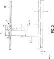
- a configuration of the touch plate 5 will now be described with reference to FIGS. 7 and 8 .
- the touch plate 5 is provided with the flat plate part 16, an A reference plane jig 24 and a B reference plane jig 25 disposed on the flat plate part 16, a floating unit 23, and the reflectors 27.
- FIGS. 7 and 8 illustrate a case in which the horizontal cross section of the long member 10 has a so-called Z shape; however, the present invention can also be applied to a long member 10 having a different cross-sectional shape by changing the arrangement position of the A reference plane jig 24 and the B reference plane jig 25.
- FIG. 8 illustrates a state in which the long member 10 comes into contact with the touch plate 5 disposed on a side different from that in FIG. 1 .
- the A reference plane jig 24 restrains the long member 10 such that the A reference plane on the long member 10 is in a reference position.
- the A reference plane jig 24 restrains movement of the long member 10 in the Y direction.
- the A reference plane jig 24 is composed of, for example, a fixed component 24A and a movable component 24B.
- the fixed component 24A is installed protruding on one surface side of the flat plate part 16.
- the movable component 24B moves closer to and away from the fixed component 24A with an actuator (not illustrated).
- an actuator not illustrated
- sandwiching is released.
- the surface of the fixed component 24A that comes into contact with the long member 10 is perpendicular to the flat surface of the flat plate part 16. This configuration ensures that the end surface of the long member 10 is pressed against the touch plate 5 and enables correct setting of the extending direction of the long member 10 when the A reference plane jig 24 restrains movement of the long member 10 in the Y direction.
- the flat plate surface of the long member 10 that comes into contact with the fixed component 24A when the fixed component 24A and the movable component 24B sandwich the long member 10 is the A reference plane.
- the B reference plane jig 25 restrains the long member 10 such that the B reference plane on the long member 10 is in a reference position.
- the B reference plane jig 25 restrains movement of the long member 10 in the Z direction.
- the B reference plane jig 25 is composed of, for example, a fixed component 25A and a movable component 25B.
- the surface of the fixed component 25A that comes into contact with the long member 10 is perpendicular to the flat surface of the flat plate part 16. This configuration ensures that the end surface of the long member 10 is pressed against the touch plate 5 and enables correct setting of the extending direction of the long member 10 when the B reference plane jig 25 restrains movement of the long member 10 in the Z direction.
- the flat plate surface of the long member 10 that comes into contact with the fixed component 25A when the fixed component 25A and the movable component 25B sandwich the long member 10 is the B reference plane.
- the floating unit 23 is installed between a support 26 and the flat plate part 16.
- the floating unit 23 allows the flat plate part 16 to move in the X direction and incline with respect to the X direction. This configuration enables the end surface of the long member 10 to appropriately come into surface contact with the surface of the flat plate part 16 of the touch plate 5.
- the support 26 is installed in a fixed manner on the table 3.
- At least three reflectors 27 are installed on the flat plate part 16, and the position of each of the reflectors 27 is detected by the laser tracker 7. This configuration enables correct calculation of the position and inclination of the flat plate part 16.
- the long member 10 to be assembled is temporarily placed on a rack or the like in the supplying position 20.
- the table 3 on which the supporting robots 4 are placed moves on the conveyor 2 so that the supporting robots 4 approach the long member 10 temporarily placed in the supplying position 20 (step S1).
- the number of the supporting robots 4 for gripping the long member 10 and the touch plate 5 with which the long member 10 comes into contact have been determined. Note that the positions of the supporting robots 4 on the table 3 have been already adjusted.
- the hand parts 8 of the supporting robots 4 grip the long member 10 and move the long member 10 from the supplying position 20 to the conveyor 2 to take out the long member 10 from the supplying position 20 (step S2).
- the hand parts 8 of the supporting robots 4 preferably grip the long member 10 in such positions that the long member 10 does not bend, that is, in such positions that tensile force or compressive force is not applied to the long member 10.
- the hand parts 8 of the supporting robots 4 are moved and the position and held shape of the long member 10 is adjusted by the supporting robots 4 corresponding to the original shape of the long member 10 stored in a memory 35 (step S3). At this time, the first end portion of the long member 10 is restrained by the touch plate 5. This operation enables correct adjustment of the position and held shape of the long member 10 with reference to the first end portion of the long member 10.
- the conveyor 2 conveys the table 3 with the supporting robots 4 gripping the long member 10. This operation allows the supporting robots 4 on the table 3 placed on the conveyor 2 to be conveyed and the long member 10 to be moved to the mounting position 21 where the mounting robot 6 can mount the other component 22 on the long member 10 (step S4).
- the hand part 37 of the gripping robot 11 is moved and the position and held shape of the long member 10 is adjusted by the gripping robot 11 corresponding to the original shape of the long member 10 stored in a memory 35 (step S5).
- Major operations of the gripping robot 11 include positional control on the basis of the reference position of the gripping robot 11 itself instead of positional control by the laser tracker 7, and positional control using the laser tracker 7 for final fine adjustment.
- the mounting robot 6 and the gripping robot 11 mount the other component 22 on the long member 10 (step S6).
- Major operations of the mounting robot 6 include positional control on the basis of the reference position of the mounting robot 6 itself instead of positional control by the laser tracker 7, and positional control using the laser tracker 7 for final fine adjustment. Since the supporting robots 4 and the gripping robot 11 have adjusted the position and held shape of the long member 10 correctly as described above, the mounting robot 6 can mount the other component 22 in a desired precise position. The supporting robots 4 may adjust the position and held shape of the long member 10 again before the mounting robots 6 mount the other component 22 on the long member 10.
- the supporting robots 4 adjust the position and the like of the long member 10 and the long member 10 is conveyed and before the mounting robots 6 mount the other component 22, it may be checked whether the long member 10 is held in the original shape or a precise position. For example, it is checked whether the long member 10 is held in the original shape by measuring the mounting position 21 of the other component 22 on the long member 10 and measuring the total length of the long member 10.
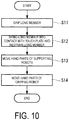
- the supporting robots 4 grip the long member 10 in such positions that the amount of deformation (the amount of bend) of the long member 10 is minimized (step S11).
- the number of the supporting robots 4 for gripping the long member 10 is determined on the basis of the total length and shape of the long member 10, the operating range of the supporting robots 4, and the like.
- the gripping positions where the amount of deformation of the long member 10 is minimized are determined through preliminary analysis on the basis of the amount of deformation of the long member 10 from the original shape of the long member 10, for example. If the touch plate 5 is used to restrain an end portion of the long member 10, the restraint imposed by the touch plate 5 is also considered as an analysis condition.
- step S12 This operation restrains the end portion of the long member 10 from moving in all of the X direction, Y direction, and Z direction.
- the touch plate 5 If the touch plate 5 is not used, the hand parts 8 of the supporting robots 4 produce errors, and it is difficult to completely prevent movement of the long member 10. Thus, it is difficult to completely restrain movement in all of the X, Y, and Z directions. Using the touch plate 5 can reduce errors and determine the reference position.
- the plurality of supporting robots 4 and the gripping robot 11 adjust the gripping position again.
- the hand parts 8 of the supporting robots 4 move to positions where the shape of the long member 10 gripped by the supporting robots 4 matches the original shape, on the basis of the original shape of the long member 10 (step S13).
- the hand part 37 of the gripping robot 11 moves to a position where the shape of the long member 10 supported by the gripping robot 11 matches the original shape, on the basis of the original shape of the long member 10 (step S14).
- the original shape is a shape of the long member 10 stored in the memory 35.
- the memory 35 stores, for example, design dimensions of the long member 10 as the original shape.
- the destination positions of the hand parts 8, 37 are positions in a coordinate with its reference (zero point) being the reference position, that is, the position where the long member 10 is restrained on the touch plate 5.
- the coordinates of the destination positions of the hand parts 8, 37 are calculated on the basis of the original shape stored in the memory 35.
- the hand parts 8, 37 move on the basis of the X, Y, Z coordinates calculated as the destination positions, the long member 10 is held in such a position that its shape matches the original shape.
- the hand parts 8, 37 have such a configuration as not to restrain the long member 10 in the X direction, that is, in the longitudinal direction of the long member 10, as described above.
- tensile force or compressive force is not applied to the long member 10 in the longitudinal direction. Accordingly, the long member 10 is not likely to deform.
- the gripping robot 11 produces less positional errors in positioning compared to the supporting robot 4.
- the gripping robot 11 which has higher positioning accuracy than the plurality of supporting robots 4, instead of the plurality of supporting robots 4, the positioning accuracy of the mounting position 21 where the other component 22 is mounted is enhanced.
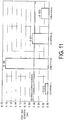
- the target long member 10 for analysis i.e. the stringer
- the other component 22 i.e. a clip
- condition (4) compared to condition (2) has enhanced positioning accuracy, and the desired accuracy can be satisfied, as a result, supporting robots 4 may have low positioning accuracy without enhancing the positioning accuracy of all of the supporting robots 4 as in condition (1), but by a single gripping robot 11 with high positioning accuracy supporting the long member 10 along with the plurality of supporting robots 4 with low positioning accuracy as in condition (4).
- the positioning accuracy of the mounting position 21 can be enhanced beyond that of the case in which the long member 10 is supported by only a plurality of supporting robots 4 with low positioning accuracy.
- the number of robots provided with a reflector on the hand part can be reduced, and the complexity of the calculations of the positional control and the work involving maintenance of the robots overall can be reduced.
- the cost of the long member assembling device 1 overall can also be reduced.
- the supporting robots 4 use the hand parts 8 to grip predetermined positions of the long member 10 located in the supplying position 20. These gripping positions may not be as precise as those when the other component 22 is mounted, and are based on positions detected by position detection units of the supporting robots 4 and the conveyor 2.
- the supporting robots 4 bring the long member 10 into contact with the touch plate 5.
- the floating unit 23 completely brings the end surface (YZ surface) of the first end portion of the long member 10 into surface contact with the flat surface (YZ surface) of the touch plate 5.
- the A reference plane jig 24 and the B reference plane jig 25 of the touch plate 5 sandwich the long member 10 in the order of the A reference plane jig 24 and the B reference plane jig 25.
- This operation imposes such restraint that the A reference plane and the B reference plane on the long member 10 are in the reference positions.
- the stoppers 13 of the supporting robots 4 release gripping of the long member 10.
- the long member 10 may be sandwiched in the order of the B reference plane jig 25 and the A reference plane jig 24, which is the inverse order of the above-described example.
- the reference coordinate is determined by, for example, detecting the reflectors 27 on the two touch plates 5 and using the positions of the detected reflectors 27 as references. Specifically, one of the reflectors 27 on the touch plate 5 disposed on the first end side of the table 3 is detected, and two of the reflectors 27 on the touch plate 5 disposed on the second end side of the table 3 are detected. This operation determines the XY plane and sets the reference coordinate.
- the reference point can be set if the reflectors can be mounted directly on the touch plate 5 at the position of the reference point (origin), but if they cannot be directly mounted, the reference point can be set by detecting three reflectors 27 on the touch plate 5 in contact with one end of the long member 10.
- the reflectors 28, 29 are always provided on the hand parts 17, 37; however, the present invention is not limited to this example.
- the detection may not be performed by the laser tracker 7 at all times.
- An error inherent in the mounting robot 6 and the gripping robot 11 may be detected preliminarily by the laser tracker 7 and stored.
- the reflectors 28, 29 are detached in mounting, and the mounting robot 6 and the gripping robot 11 are mounted in consideration of the stored error. This can enhance precision in mounting the component 22.
- the supporting robots 4 and the touch plates 5 are placed on the conveyor 2 in the above description; however, the present invention is not limited to this example.
- a configuration is possible in which the mounting robot 6 and the gripping robot 11 may be placed on the conveyor in a movable manner relative to the supporting robots 4 and the touch plates 5.
- the supporting robots 4 are arranged at predetermined intervals on the table 3 and integrated with the table 3 in the above-described embodiment; however, the present invention is not limited to this example.
- the supporting robots 4 may be installed in a self-propelled manner on the table 3 on the basis of the length and shape of the long member 10 to be gripped.
- positional information on the supporting robots 4 with respect to a reference position on the table 3 is also used to position the hand parts 8 of the supporting robots 4.
Landscapes
- Engineering & Computer Science (AREA)
- Mechanical Engineering (AREA)
- Robotics (AREA)
- Manufacturing & Machinery (AREA)
- Transportation (AREA)
- Aviation & Aerospace Engineering (AREA)
- Orthopedic Medicine & Surgery (AREA)
- General Health & Medical Sciences (AREA)
- Health & Medical Sciences (AREA)
- Human Computer Interaction (AREA)
- Automatic Assembly (AREA)
- Manipulator (AREA)
- Electrophotography Configuration And Component (AREA)
Applications Claiming Priority (2)
| Application Number | Priority Date | Filing Date | Title |
|---|---|---|---|
| JP2015167986A JP6498568B2 (ja) | 2015-08-27 | 2015-08-27 | 組立体製造装置及び組立体製造方法 |
| PCT/JP2016/070602 WO2017033604A1 (fr) | 2015-08-27 | 2016-07-12 | Dispositif de fabrication d'ensemble et procédé de fabrication d'ensemble |
Publications (2)
| Publication Number | Publication Date |
|---|---|
| EP3287228A1 true EP3287228A1 (fr) | 2018-02-28 |
| EP3287228A4 EP3287228A4 (fr) | 2018-04-11 |
Family
ID=58099857
Family Applications (1)
| Application Number | Title | Priority Date | Filing Date |
|---|---|---|---|
| EP16838951.8A Withdrawn EP3287228A4 (fr) | 2015-08-27 | 2016-07-12 | Dispositif de fabrication d'ensemble et procédé de fabrication d'ensemble |
Country Status (7)
| Country | Link |
|---|---|
| US (1) | US10556350B2 (fr) |
| EP (1) | EP3287228A4 (fr) |
| JP (1) | JP6498568B2 (fr) |
| KR (1) | KR102047169B1 (fr) |
| CN (1) | CN107614194B (fr) |
| CA (1) | CA2987024C (fr) |
| WO (1) | WO2017033604A1 (fr) |
Cited By (11)
| Publication number | Priority date | Publication date | Assignee | Title |
|---|---|---|---|---|
| EP3275586A4 (fr) * | 2015-10-28 | 2018-04-18 | Mitsubishi Heavy Industries, Ltd. | Appareil et procédé d'assemblage et de fabrication |
| CN112026193A (zh) * | 2020-08-21 | 2020-12-04 | 王茹新 | 一种医疗器械组装装置 |
| EP4000825A1 (fr) | 2020-11-18 | 2022-05-25 | The Boeing Company | Rognage des bords pour la fabrication d'aéronef en ligne mobile |
| EP4001129A1 (fr) | 2020-11-18 | 2022-05-25 | The Boeing Company | Rognage des bords pour la fabrication d'aéronef en ligne mobile |
| EP4000826A1 (fr) | 2020-11-18 | 2022-05-25 | The Boeing Company | Rognage des bords pour la fabrication d'aéronef en ligne mobile |
| EP4011535A1 (fr) | 2020-11-18 | 2022-06-15 | The Boeing Company | Rognage des bords pour fabrication d'aéronef sur ligne mobile |
| NL2027432B1 (en) * | 2021-01-26 | 2022-08-19 | Boeing Co | Edge trimming for moving-line fabrication of aircraft |
| NL2027430B1 (en) * | 2021-01-26 | 2022-08-19 | Boeing Co | Edge trimming for moving-line fabrication of aircraft |
| NL2027426B1 (en) * | 2021-01-26 | 2022-08-26 | Boeing Co | Edge trimming for moving-line fabrication of aircraft |
| NL2027427B1 (en) * | 2021-01-26 | 2022-08-26 | Boeing Co | Edge trimming for moving-line fabrication of aircraft |
| US12202164B2 (en) | 2020-11-18 | 2025-01-21 | The Boeing Company | Edge trimming for moving-line fabrication of aircraft |
Families Citing this family (3)
| Publication number | Priority date | Publication date | Assignee | Title |
|---|---|---|---|---|
| JP7218538B2 (ja) * | 2018-10-17 | 2023-02-07 | 京セラドキュメントソリューションズ株式会社 | 組立装置及び構造物製造方法 |
| JP2020085596A (ja) | 2018-11-21 | 2020-06-04 | 三菱重工業株式会社 | 位置測定システム及び位置測定方法 |
| WO2024100717A1 (fr) * | 2022-11-07 | 2024-05-16 | 株式会社ニコン | Système de mesure de position et procédé de mesure de position |
Family Cites Families (17)
| Publication number | Priority date | Publication date | Assignee | Title |
|---|---|---|---|---|
| US4143448A (en) * | 1977-11-18 | 1979-03-13 | Energy Systems, Inc. | Method and apparatus for manufacturing solar heater panels |
| US4334346A (en) * | 1979-09-04 | 1982-06-15 | A. Park Smoot | Method and apparatus for fabricating studs, joists and the like |
| US5910894A (en) * | 1994-01-11 | 1999-06-08 | Sensor Adaptive Machines, Inc. | Sensor based assembly tooling improvements |
| US6314630B1 (en) * | 1996-03-22 | 2001-11-13 | The Boeing Company | Determinant wing assembly |
| US6170157B1 (en) * | 1996-03-22 | 2001-01-09 | The Boeing Company | Determinant spar assembly |
| JP2001300823A (ja) * | 2000-04-19 | 2001-10-30 | Japan Aircraft Mfg Co Ltd | 組立治具装置 |
| JP2001334426A (ja) * | 2000-05-29 | 2001-12-04 | Honda Motor Co Ltd | 汎用式治具における機種切換装置 |
| US6855099B2 (en) | 2001-10-31 | 2005-02-15 | The Boeing Company | Manufacturing system for aircraft structures and other large structures |
| KR100641585B1 (ko) | 2006-03-24 | 2006-11-02 | 서금석 | 호스 절단장치 |
| JP2011027670A (ja) * | 2009-07-29 | 2011-02-10 | Hitachi Plant Technologies Ltd | 三次元位置合わせ方法 |
| US8619265B2 (en) * | 2011-03-14 | 2013-12-31 | Faro Technologies, Inc. | Automatic measurement of dimensional data with a laser tracker |
| US9610693B2 (en) * | 2012-01-17 | 2017-04-04 | The Boeing Company | Robot for clamping onto upright frame members |
| US20130345848A1 (en) * | 2012-06-20 | 2013-12-26 | Kabushiki Kaisha Yaskawa Denki | Robot system and method for manufacturing fitting |
| DE202013101036U1 (de) * | 2013-03-08 | 2014-08-01 | Kuka Systems Gmbh | Montiereinrichtung |
| US9364926B2 (en) * | 2013-05-02 | 2016-06-14 | The Boeing Company | System and method of assembling components |
| US9745081B2 (en) | 2013-07-12 | 2017-08-29 | The Boeing Company | Apparatus and method for moving a structure in a manufacturing environment |
| JP6629001B2 (ja) * | 2015-08-03 | 2020-01-15 | 三菱重工業株式会社 | 組立体製造装置及び組立体製造方法 |
-
2015
- 2015-08-27 JP JP2015167986A patent/JP6498568B2/ja active Active
-
2016
- 2016-07-12 CN CN201680029115.0A patent/CN107614194B/zh not_active Expired - Fee Related
- 2016-07-12 EP EP16838951.8A patent/EP3287228A4/fr not_active Withdrawn
- 2016-07-12 KR KR1020177034430A patent/KR102047169B1/ko not_active Expired - Fee Related
- 2016-07-12 US US15/576,907 patent/US10556350B2/en active Active
- 2016-07-12 WO PCT/JP2016/070602 patent/WO2017033604A1/fr not_active Ceased
- 2016-07-12 CA CA2987024A patent/CA2987024C/fr not_active Expired - Fee Related
Cited By (12)
| Publication number | Priority date | Publication date | Assignee | Title |
|---|---|---|---|---|
| EP3275586A4 (fr) * | 2015-10-28 | 2018-04-18 | Mitsubishi Heavy Industries, Ltd. | Appareil et procédé d'assemblage et de fabrication |
| US10913134B2 (en) | 2015-10-28 | 2021-02-09 | Mitsubishi Heavy Industries, Ltd. | Assembly manufacturing apparatus and assembly manufacturing method |
| CN112026193A (zh) * | 2020-08-21 | 2020-12-04 | 王茹新 | 一种医疗器械组装装置 |
| EP4000825A1 (fr) | 2020-11-18 | 2022-05-25 | The Boeing Company | Rognage des bords pour la fabrication d'aéronef en ligne mobile |
| EP4001129A1 (fr) | 2020-11-18 | 2022-05-25 | The Boeing Company | Rognage des bords pour la fabrication d'aéronef en ligne mobile |
| EP4000826A1 (fr) | 2020-11-18 | 2022-05-25 | The Boeing Company | Rognage des bords pour la fabrication d'aéronef en ligne mobile |
| EP4011535A1 (fr) | 2020-11-18 | 2022-06-15 | The Boeing Company | Rognage des bords pour fabrication d'aéronef sur ligne mobile |
| US12202164B2 (en) | 2020-11-18 | 2025-01-21 | The Boeing Company | Edge trimming for moving-line fabrication of aircraft |
| NL2027432B1 (en) * | 2021-01-26 | 2022-08-19 | Boeing Co | Edge trimming for moving-line fabrication of aircraft |
| NL2027430B1 (en) * | 2021-01-26 | 2022-08-19 | Boeing Co | Edge trimming for moving-line fabrication of aircraft |
| NL2027426B1 (en) * | 2021-01-26 | 2022-08-26 | Boeing Co | Edge trimming for moving-line fabrication of aircraft |
| NL2027427B1 (en) * | 2021-01-26 | 2022-08-26 | Boeing Co | Edge trimming for moving-line fabrication of aircraft |
Also Published As
| Publication number | Publication date |
|---|---|
| WO2017033604A1 (fr) | 2017-03-02 |
| JP2017042881A (ja) | 2017-03-02 |
| US10556350B2 (en) | 2020-02-11 |
| CA2987024A1 (fr) | 2017-03-02 |
| US20180147729A1 (en) | 2018-05-31 |
| EP3287228A4 (fr) | 2018-04-11 |
| JP6498568B2 (ja) | 2019-04-10 |
| KR20170139678A (ko) | 2017-12-19 |
| KR102047169B1 (ko) | 2019-11-20 |
| CN107614194A (zh) | 2018-01-19 |
| CA2987024C (fr) | 2021-05-18 |
| CN107614194B (zh) | 2020-02-07 |
Similar Documents
| Publication | Publication Date | Title |
|---|---|---|
| US10556350B2 (en) | Assembly body manufacturing device and assembly body manufacturing method | |
| US10668583B2 (en) | Assembly body manufacturing device and assembly body manufacturing method | |
| US10814488B2 (en) | Assembly body manufacturing device and assembly body manufacturing method | |
| CA2983790C (fr) | Appareil et procede d'assemblage et de fabrication | |
| CN104044131A (zh) | 机器人系统、校正方法及被加工物制造方法 | |
| US20210299861A1 (en) | Control system and control method | |
| JP2017136928A (ja) | 保持治具固定装置 | |
| WO2017018107A1 (fr) | Système de positionnement et procédé de positionnement |
Legal Events
| Date | Code | Title | Description |
|---|---|---|---|
| STAA | Information on the status of an ep patent application or granted ep patent |
Free format text: STATUS: THE INTERNATIONAL PUBLICATION HAS BEEN MADE |
|
| PUAI | Public reference made under article 153(3) epc to a published international application that has entered the european phase |
Free format text: ORIGINAL CODE: 0009012 |
|
| STAA | Information on the status of an ep patent application or granted ep patent |
Free format text: STATUS: REQUEST FOR EXAMINATION WAS MADE |
|
| 17P | Request for examination filed |
Effective date: 20171120 |
|
| AK | Designated contracting states |
Kind code of ref document: A1 Designated state(s): AL AT BE BG CH CY CZ DE DK EE ES FI FR GB GR HR HU IE IS IT LI LT LU LV MC MK MT NL NO PL PT RO RS SE SI SK SM TR |
|
| AX | Request for extension of the european patent |
Extension state: BA ME |
|
| A4 | Supplementary search report drawn up and despatched |
Effective date: 20180313 |
|
| RIC1 | Information provided on ipc code assigned before grant |
Ipc: G05B 19/402 20060101ALN20180307BHEP Ipc: B64F 5/10 20170101ALI20180307BHEP Ipc: B64C 1/06 20060101ALI20180307BHEP Ipc: B21J 15/14 20060101ALI20180307BHEP Ipc: B23P 19/10 20060101AFI20180307BHEP Ipc: G05B 19/418 20060101ALN20180307BHEP Ipc: B25J 9/16 20060101ALN20180307BHEP Ipc: B64C 3/18 20060101ALI20180307BHEP |
|
| DAV | Request for validation of the european patent (deleted) | ||
| DAX | Request for extension of the european patent (deleted) | ||
| STAA | Information on the status of an ep patent application or granted ep patent |
Free format text: STATUS: EXAMINATION IS IN PROGRESS |
|
| 17Q | First examination report despatched |
Effective date: 20201123 |
|
| STAA | Information on the status of an ep patent application or granted ep patent |
Free format text: STATUS: THE APPLICATION IS DEEMED TO BE WITHDRAWN |
|
| 18D | Application deemed to be withdrawn |
Effective date: 20230418 |