EP3287318B1 - Fixation pour le transport et arrimage du chargement pour contenants - Google Patents
Fixation pour le transport et arrimage du chargement pour contenants Download PDFInfo
- Publication number
- EP3287318B1 EP3287318B1 EP17186076.0A EP17186076A EP3287318B1 EP 3287318 B1 EP3287318 B1 EP 3287318B1 EP 17186076 A EP17186076 A EP 17186076A EP 3287318 B1 EP3287318 B1 EP 3287318B1
- Authority
- EP
- European Patent Office
- Prior art keywords
- container
- vehicle
- traverses
- transport
- load securing
- Prior art date
- Legal status (The legal status is an assumption and is not a legal conclusion. Google has not performed a legal analysis and makes no representation as to the accuracy of the status listed.)
- Active
Links
- 238000003780 insertion Methods 0.000 claims description 6
- 230000037431 insertion Effects 0.000 claims description 6
- 238000000034 method Methods 0.000 claims description 6
- 239000002184 metal Substances 0.000 claims description 3
- 239000004033 plastic Substances 0.000 claims description 3
- 229920000049 Carbon (fiber) Polymers 0.000 claims 1
- 239000004917 carbon fiber Substances 0.000 claims 1
- VNWKTOKETHGBQD-UHFFFAOYSA-N methane Chemical compound C VNWKTOKETHGBQD-UHFFFAOYSA-N 0.000 claims 1
- 239000004918 carbon fiber reinforced polymer Substances 0.000 description 1
- 230000001419 dependent effect Effects 0.000 description 1
- 238000006073 displacement reaction Methods 0.000 description 1
- 239000002990 reinforced plastic Substances 0.000 description 1
Images


Classifications
-
- B—PERFORMING OPERATIONS; TRANSPORTING
- B60—VEHICLES IN GENERAL
- B60P—VEHICLES ADAPTED FOR LOAD TRANSPORTATION OR TO TRANSPORT, TO CARRY, OR TO COMPRISE SPECIAL LOADS OR OBJECTS
- B60P7/00—Securing or covering of load on vehicles
- B60P7/06—Securing of load
- B60P7/08—Securing to the vehicle floor or sides
- B60P7/0892—Securing to the vehicle floor or sides by preventing lateral movement of the load, e.g. using stop blocks
Definitions
- the invention relates to a transport and load securing for containers and an associated method.
- a generic fuse is in US 3754516 A disclosed.
- anti-slip mats are arranged under the containers and on the loading area in order to prevent containers from slipping on the loading area during transport.
- straps can alternatively or additionally be used to secure the containers on the loading surface.
- the containers are standardized and the containers have a grid dimension, ie there is a kind of "kit” on containers.
- the containers generally have the same function and the same appearance, but have different sizes, for example in the base area and / or the container height.
- the containers can thereby be stacked and / or stored and / or transported in a simplified manner.
- a grid dimension for a set of containers is often chosen such that the base area of a container is a whole multiple of the base area of a "base container", ie the smallest container.
- base container ie the smallest container.
- smaller containers can be arranged on larger containers so that the base area of the larger container is fully utilized. For example, two 1 ⁇ 2 containers on one 1/1 containers are placed, whereby the base of the 1/1 container is fully used.
- a disadvantage of the known transport and load securing devices is that the success of securing the containers is heavily dependent on the user.
- the vehicle cross members and / or the container cross members preferably each run parallel to one another.
- the vehicle traverses are advantageously connected to the vehicle by means of a screw connection or in particular a detachable plug connection.
- the vehicle crossbars are preferably arranged in the direction of travel of the vehicle, perpendicular to it or at any angle in between.
- the vehicle crossbars advantageously each have one end of a plug connection in the longitudinal direction, in particular a dovetail connection, so that the vehicle crossbars can be connected to one another in the longitudinal direction thereof.
- the vehicle and / or container crossbars preferably consist of metal or plastic, in particular CFRP reinforced.
- the vehicle crossbars advantageously have an insertion section for inserting a container crossbar between adjacent vehicle crossbars and one Undercut to move the container crossbar between the vehicle crossbar and the loading area of the vehicle.
- the opposite container traverses are advantageously adjacent container traverses.
- the container crossbars are preferably arranged perpendicular to the vehicle crossbars.
- the container traverses are advantageously mirror-symmetrical to the longitudinal and / or transverse axis.
- a grid dimension of the engagement shells is advantageously matched to a grid dimension of the container feet of the containers, so that all container feet on one side of the container are held by a container traverse.
- Container traverses are preferably attached to the vehicle and / or the vehicle traverses.
- the engagement shells are advantageously formed without an undercut in order to prevent the container from slipping parallel to the loading area.
- the engaging shells preferably have a vertical holding means, in particular a projection, in order to prevent the container from being displaced perpendicularly to the loading area of the vehicle.
- the dimensions of the projection in the engagement shell and a corresponding undercut in the container base are preferably such that the container base is supported on the one hand by the associated container crossmember and on the other by the loading area of the vehicle (double support).
- the vehicle can be a truck, a van, a car or a flatbed truck.
- the container is advantageously a storage box with or without a lid.
- the cross section of the container feet is advantageously round, for example circular or elliptical, or polygonal, for example rectangular or square.
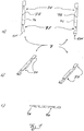
- Fig. 1 shows different views of a pair of first vehicle cross members 7
- Figure 2 shows different views of a pair of second vehicle cross members 7.
- the two pairs of vehicle cross members 7 can each be connected to one another via a dovetail connection 13.
- the vehicle cross members 7 of the Fig. 1 a groove 13N and the vehicle cross members 7 of the Fig. 2 a spring 13F of a dovetail joint 13.
- the two pairs of vehicle traverses 7 the Figures 1 and 2 Connected to one another via the dovetail connection, they are fastened to the loading area 5L of a vehicle 5, the length of the assembled vehicle traverses 7 corresponding to a desired length and, for example, corresponding to the length of the loading area 5L in the direction of travel 5F of the vehicle 5.
- the first and second pairs of vehicle cross members 7 are as from Fig. 1a ) and 2a ) can be seen, each mirror-symmetrical.
- the vehicle traverses are formed as hollow profiles made of metal, alternatively, for example, made of a plastic, in particular a reinforced plastic.
- Through bores 7B are provided in the vehicle crossbars 7 in order to fasten the vehicle crossbars 7 to the loading area 5L of the vehicle 5 by means of screws.
- insertion sections 7E are provided to arrange a container traverse 9 between them, as further described below.
- vehicle traverses 7 have undercuts 7H assigned to the insertion sections 7E, along which the container traverses 9 are displaceable, as also described below.
- FIG. 3 Different views of the container traverse 9 for arrangement between two vehicle traverses 7 are shown.
- the container traverse 9 is also a metallic hollow profile.
- the container crossmember 9 each has an undercut 9H, as a result of which an intermediate section 9Z projecting in the longitudinal direction is formed.
- the intermediate section is provided for arrangement between the loading area 5L and a vehicle crossbar 7 in the region of the undercut 7H, as described further below.
- vertical height of the intermediate section 9Z perpendicular to the longitudinal direction of the container crossbar 9 therefore corresponds to the height of the undercut 7H of the vehicle crossbar.
- Opposing engagement shells 9E are formed on opposite longitudinal sides 9L of the container traverse, which are formed in a semicircular shape.
- the engaging shells 9E are substantially in the shape of a half cylinder, but a semicircular projection 9V is formed in the center thereof. With these engagement shells it is possible to enclose a container base 3F of a container 3 in a semicircular manner, as described further below.
- the container traverse 9 is constructed symmetrically along the longitudinal axis thereof. Furthermore, the container crossbar 9 is symmetrical perpendicular to an axis which divides the container crossbar 9 centrally in the longitudinal direction.
- Fig. 4 shows different views of the container base 3F of a container 3.
- the container base 3F has an essentially cylindrically symmetrical shape.
- upper end is formed a recess to connect the container base 3F with its container 3.
- an annular undercut 3H is formed in the container base 3.
- the projection 9V of the engagement shell 9E engages in a semicircular manner as described below.
- the axial of the undercut 3H in Fig. 4c corresponds to the thickness of the projection 9V in the same direction.
- FIGS. 5 ) and 6 ) show different views of the transport and load securing 1, with container feet 3 of containers 3, not shown, also being shown for easier understanding.
- the pair of first vehicle traverses 7 of the Fig. 1 is connected to the pair of second vehicle cross members 7 via the dovetail connection 13, ie the groove 13N has received the spring 13F, as a result of which a mechanical plug connection is formed between the vehicle cross members 7.
- the engagement shells 9E enclose the container feet 3F in a semicircular shape, the projection 9V also engaging in the undercut 3H in a semicircular shape. Because the thickness of the projection 9V corresponds to the height of the undercut 3H, each container foot 3F presses on the one hand with its undercut 3H on the projection 9V and on the other hand with its free end on the loading area 5L of the vehicle 5.
- the container base 3F is no longer displaceable in the axial direction thereof.
- the container foot 3F is held securely in the axial direction and is not displaceable. In this way, during a transport of containers 3 with a vehicle 5, the lifting of containers 3 from the loading area 5L of the vehicle 5 can be prevented.
- FIG Fig. 7 In order to secure the transport and load of containers 3 on a vehicle 5, reference is made to FIG Fig. 7 ) proceeded as follows: This in Fig. 7 Flatbed vehicle 5 shown has a loading area 5L. The arrow 5F indicates the direction of travel of the vehicle 5 when the vehicle 5 is traveling forward.
- the pair of first vehicle cross members 7 becomes the Fig. 1 with the pair of second cross members 7 of the Fig. 2 mechanically connected by means of the dovetail connection 13.
- the interconnected vehicle traverses 7 are arranged parallel to one another on the loading surface 5L of the vehicle, the relative distance from one another depending on the length of the container traverses 9.
- the vehicle traverses 7 are firmly connected to the loading area 5L of the vehicle 5.
- screws are screwed through the through holes 7B of the vehicle crossbar 7 into the loading area 5L in order to form a screw connection 11 between the vehicle crossbars 7 and the vehicle 5.
- Alternative mechanical connections are possible.
- a plug connection could be formed between the vehicle cross members 7 and the loading area 5L.
- a first container crossbar 9 is arranged between the vehicle crossbars 7, the intermediate sections 9Z of the container crossbar 9 being arranged in the insertion sections 7E of the vehicle crossbar 7.
- the container traverse 9 is lowered in an orientation onto the loading surface 5L that corresponds to the orientation of the Fig. 3c ) corresponds, but the container crossbar 9 is rotated by 180 ° along the longitudinal axis.
- the container crossbar 9 is displaced in the direction of travel 5F so that the intermediate section 9Z is arranged completely in the region of the undercut 7H of the vehicle crossbar and is thus arranged between the loading surface 5L and the vehicle crossbar 7. Because the thickness of the intermediate section 9Z corresponds to the height of the undercut 7H at this point, a displacement of the container traverse 9 perpendicular to the loading area 5L is not possible.
- the container crossbar 9 is fastened in this position, in the present case screws are screwed through the container crossbar 9 and into the loading area 5L of the vehicle.
- the container traverse 9 can be screwed to the vehicle traverse 7.
- latching or plug connections can be formed in a known manner between the container crossbar 9 and the vehicle crossbar 7.
- a container 3 with container feet 3F is shifted in the four corners of its base surface in the direction of travel 5F on the loading surface 5L until the container feet 5F engage in the engagement shells 9E of the container traverse 9.
- the engagement shells 9E each surround the container base 3F in a semicircular shape, the projection 9V engaging in the undercut 3H.
- a further container crossbar 9 is now arranged between the vehicle crossbars 7, lowered onto the loading surface 5L and shifted in the direction of travel 5F, as described above for the first container crossbar 9, until the second container crossbar 9 with its engaging shells 9E on the container feet 3F strikes.
- the engagement shells 9E again encircle the container feet 3F in a semicircular shape, the projection 9V engaging in the undercut 3H, as described above.
- the second container traverse 9 is fastened in this position.
- the attachment takes place as described above for the attachment of the first container traverse 9, i.e. in the present case by means of a screw connection.
- the container 3 is now held on the vehicle 5 by the transport and load securing device 1: due to the cylindrical shape of the engagement shells 9E and the container feet 3F, the container 3 is displaced in the plane of the loading area 5L prevents.
- the projection 9V in the container traverse and the undercut 3H in the container base 3 also prevent the container 3 from being displaced perpendicularly to the loading surface 5L.
- the undercut 3H and the projection 9V were selected as the vertical holding means.
- Alternative embodiments of the vertical holding means are possible.
- the undercut is formed in the engagement shell and the projection on the container base.
- two or more undercuts can work together with a corresponding number of projections, the undercuts being able to be formed both in the container feet and in the engaging shells (and accordingly the projections in the engaging shells or the container feet).
- cone-shaped undercuts or projections are conceivable or combinations of ring-shaped and cone-shaped undercuts and projections.
- the engagement shells encircle the container feet in a semicircle, ie in an angular range of 180 °.
- the angular range should preferably be greater than 90 ° in order to achieve a good or sufficient hold.
Landscapes
- Engineering & Computer Science (AREA)
- Transportation (AREA)
- Mechanical Engineering (AREA)
- Body Structure For Vehicles (AREA)
- Passenger Equipment (AREA)
- Fittings On The Vehicle Exterior For Carrying Loads, And Devices For Holding Or Mounting Articles (AREA)
Claims (15)
- Système de blocage pour le transport et le chargement (1) pour des contenants (3) avec des pieds de contenant (3F) sur une surface de chargement (5L) d'un véhicule (5), en particulier d'un véhicule automobile, avec des traverses de véhicule (7) se faisant face par paire, qui sont reliées de manière solidaire au véhicule (5), des traverses de contenant (9) se faisant face par paire, qui s'étendent entre les traverses de véhicule (7), dans lequel les traverses de contenant (9) présentent au niveau de leurs côtés longitudinaux (9L) respectivement au moins une coque de prise (9E) pour respectivement un pied de contenant (3F) pour maintenir par complémentarité de forme par endroits un pied de contenant (3F) avec la coque de prise (9E), et des pieds de contenant (3F) sont maintenus au niveau de côtés se faisant face du contenant (3) par des coques de prise (9E) de traverses de contenant (9) se faisant face,
caractérisé en ce que
les traverses de contenant (9) sont disposées de manière perpendiculaire par rapport aux traverses de véhicule (7). - Système de blocage pour le transport et le chargement selon la revendication 1, caractérisé en ce que des traverses de véhicule (7) et/ou des traverses de contenant (9) s'étendent respectivement de manière parallèle les unes par rapport aux autres.
- Système de blocage pour le transport et le chargement selon la revendication 1 ou 2, caractérisé en ce que les traverses de véhicule (7) sont reliées au véhicule (5) au moyen d'une liaison par vissage ou d'une liaison par enfichage (11) en particulier amovible.
- Système de blocage pour le transport et le chargement selon l'une quelconque des revendications précédentes, caractérisé en ce que les traverses de véhicule (7) sont disposées dans une direction de déplacement (5F) du véhicule (5) de manière perpendiculaire par rapport à celle-ci ou selon un angle quelconque de manière intercalée.
- Système de blocage pour le transport et le chargement selon l'une quelconque des revendications précédentes, caractérisé en ce que les traverses de véhicule (7) présentent dans le sens longitudinal respectivement une extrémité d'une liaison par enfichage (13), en particulier d'une liaison en queue d'aronde de sorte que les traverses de véhicule (7) peuvent être reliées de manière enfichable les unes aux autres dans le sens longitudinal de celles-ci.
- Système de blocage pour le transport et le chargement selon l'une quelconque des revendications précédentes, caractérisé en ce que des traverses de véhicule et/ou de contenant (7, 9) sont constituées de métal ou de matière plastique, en particulier sont renforcées par des matières plastiques renforcées par des fibres de carbone.
- Système de blocage pour le transport et le chargement selon l'une quelconque des revendications précédentes, caractérisé en ce que les traverses de véhicule (7) présentent une section d'introduction (7E) pour introduire une traverse de contenant (9) entre des traverses de véhicule (7) adjacentes, et une contre-dépouille (7H) pour faire coulisser la traverse de contenant (9) entre une traverse de véhicule (7) et la surface de chargement (5L) du véhicule (5).
- Système de blocage pour le transport et le chargement selon l'une quelconque des revendications précédentes, présentant au moins une des caractéristiques suivantes :dans lequel les traverses de contenant (9) se faisant face sont des traverses de contenant (9) adjacentes ;dans lequel les traverses de contenant (9) sont réalisées de manière symétrique en miroir par rapport à l'axe longitudinal et/ou transversal.
- Système de blocage pour le transport et le chargement selon l'une quelconque des revendications précédentes, caractérisé en ce qu'un pas des coques de prise (9E) est adapté à un pas des pieds de contenant (3F) des contenants (3) afin que tous les pieds de contenant (3F) d'un côté du contenant (3) soient maintenus par une traverse de contenant (9).
- Système de blocage pour le transport et le chargement selon l'une quelconque des revendications précédentes, caractérisé en ce que les traverses de contenant (9) sont fixées au niveau du véhicule (5) et/ou au niveau des traverses de véhicule (7).
- Système de blocage pour le transport et le chargement selon l'une quelconque des revendications précédentes, caractérisé en ce que les coques de prise (9E) sont formées sans contre-dépouille pour empêcher tout glissement du contenant (3) de manière parallèle par rapport à la surface de chargement (5L).
- Système de blocage pour le transport et le chargement selon l'une quelconque des revendications précédentes, caractérisé en ce que les coques de prise (9E) présentent un moyen de maintien vertical (9V), en particulier une partie faisant saillie (9V), pour empêcher tout coulissement du contenant (3) de manière perpendiculaire par rapport à la surface de chargement (5L) du véhicule (5), dans lequel en particulier la partie faisant saillie (9V) dans la coque de prise (9E) et une contre-dépouille (3H) correspondante dans le pied de contenant (3F) sont adaptées l'une à l'autre sur le plan des dimensions de telle sorte que le pied de contenant (3F) est soutenu d'une part par la traverse de contenant (9) associée et d'autre part par la surface de chargement (5L) du véhicule.
- Système de blocage pour le transport et le chargement selon l'une quelconque des revendications précédentes, qui présente au moins une des caractéristiques suivantes :dans lequel le véhicule (5) est un poids lourd, un transporteur, un véhicule de tourisme ou un camion à plateau ;dans lequel le contenant (3) est un boîtier de stockage avec ou sans couvercle ; etdans lequel la section transversale des pieds de contenant (3F) est ronde ou circulaire ou de forme elliptique ou polygonale ou rectangulaire ou carrée.
- Procédé servant au blocage pour le transport et le chargement (1) d'un contenant (3) avec des pieds de contenant (3F) au niveau d'une surface de chargement (5L) d'un véhicule (5), en particulier d'un véhicule automobile, avec un système de blocage pour le transport et le chargement selon la revendication 1, comprenant :a) la fixation de traverses de véhicule (7) se faisant dace au niveau de la surface de chargement (5L) ;b) la disposition et la fixation d'une première traverse de contenant (9) entre les traverses de véhicule (7) ;c) le glissement de pieds de contenant (3F) d'un contenant (3) au niveau de la traverse de contenant (9), pour maintenir par complémentarité de forme par endroits avec au moins une coque de prise (9E) de la première traverse de contenant (9) un pied de contenant (3F), etd) la disposition et la fixation d'une deuxième traverse de contenant (9) entre les traverses de véhicule (7) pour maintenir par complémentarité de forme par endroits avec au moins une coque de prise (9E) de la deuxième traverse de contenant (9) un pied de contenant (3F) du contenant (3),caractérisé en ce que
les traverses de contenant (9) sont disposées de manière perpendiculaire par rapport aux traverses de véhicule (7). - Procédé selon la revendication précédente, caractérisé par la répétition des étapes b) à d) avec respectivement au moins une autre traverse de contenant (9) avec le contenant (3) associé pour maintenir au moins un autre contenant (3) au niveau de la surface de chargement (5L).
Applications Claiming Priority (1)
| Application Number | Priority Date | Filing Date | Title |
|---|---|---|---|
| DE102016115569.1A DE102016115569A1 (de) | 2016-08-23 | 2016-08-23 | Transport- und Ladungssicherung für Behälter |
Publications (2)
| Publication Number | Publication Date |
|---|---|
| EP3287318A1 EP3287318A1 (fr) | 2018-02-28 |
| EP3287318B1 true EP3287318B1 (fr) | 2019-12-18 |
Family
ID=59631601
Family Applications (1)
| Application Number | Title | Priority Date | Filing Date |
|---|---|---|---|
| EP17186076.0A Active EP3287318B1 (fr) | 2016-08-23 | 2017-08-13 | Fixation pour le transport et arrimage du chargement pour contenants |
Country Status (2)
| Country | Link |
|---|---|
| EP (1) | EP3287318B1 (fr) |
| DE (1) | DE102016115569A1 (fr) |
Families Citing this family (2)
| Publication number | Priority date | Publication date | Assignee | Title |
|---|---|---|---|---|
| CN110481416B (zh) * | 2019-09-23 | 2024-04-19 | 北京睿泽恒镒科技股份公司 | 一种货物钢挡架及货车 |
| CN111873892B (zh) * | 2020-08-05 | 2021-07-09 | 万金芬 | 一种城郊铁路抢修用的工具运输机器人 |
Family Cites Families (4)
| Publication number | Priority date | Publication date | Assignee | Title |
|---|---|---|---|---|
| DE1223763B (de) * | 1965-03-24 | 1966-08-25 | Pfaff Ag G M | Einrichtung zum Festhalten von Behaeltern auf der Ladeflaeche eines Fahrzeuges |
| US3754516A (en) * | 1970-12-23 | 1973-08-28 | Brammall Inc | Parallel motion mechanism |
| US5427487A (en) * | 1993-06-02 | 1995-06-27 | Brosfske; Frederic G. | Cargo stabilizer for pickup trucks |
| FR2746066B1 (fr) * | 1996-03-12 | 1998-06-05 | Dispositif de fixation amovible de charges cylindriques sur un vehicule |
-
2016
- 2016-08-23 DE DE102016115569.1A patent/DE102016115569A1/de not_active Withdrawn
-
2017
- 2017-08-13 EP EP17186076.0A patent/EP3287318B1/fr active Active
Non-Patent Citations (1)
| Title |
|---|
| None * |
Also Published As
| Publication number | Publication date |
|---|---|
| DE102016115569A1 (de) | 2018-03-01 |
| EP3287318A1 (fr) | 2018-02-28 |
Similar Documents
| Publication | Publication Date | Title |
|---|---|---|
| DE3916975C2 (fr) | ||
| AT522666A1 (de) | Transportbehälter | |
| AT521362B1 (de) | Stapelbare Kiste | |
| DE19717667B4 (de) | Längsführung für Fahrzeugsitz mit zwei länglichen Schienen und Führungsmitteln | |
| EP3287318B1 (fr) | Fixation pour le transport et arrimage du chargement pour contenants | |
| EP3354586A1 (fr) | Conteneur de transport, en particulier conteneur-palette | |
| EP3235681A1 (fr) | Structure de véhicule utilitaire avec sécurisation de charge pour en autres des bobines | |
| EP3491970B1 (fr) | Boîte pour étagères | |
| DE102011109371A1 (de) | Verriegelungsvorrichtung | |
| DE102016124447A1 (de) | Regalbediengerät | |
| EP2767659B1 (fr) | Guide à barres rondes réglable en hauteur | |
| DE3927736C2 (fr) | ||
| EP3623219B1 (fr) | Profil de sécurité de chargement ainsi que surface de chargement permettant de recevoir une cargaison transportée | |
| DE202009018596U1 (de) | Modularer Transportbehälter | |
| DE202008007158U1 (de) | Vorrichtung zur Lagerung mindestens eines Behälters, insbesondere eines Universalladeträgers | |
| EP3222464B1 (fr) | Système de cadre pour carrosseries de véhicules automobiles | |
| DE202008012869U1 (de) | Vorrichtung zur vertikalen Festlegung von Ladegut auf Ladeflächen von Behältnissen | |
| EP3363748B1 (fr) | Récipient empilable et emboitable | |
| EP3978396B1 (fr) | Dispositif d'empilage pour éléments de grue à flèche à treillis | |
| DE102024002307B3 (de) | Transportwagensystem mit Stapelsicherung | |
| EP3642126B1 (fr) | Système de rails, caisse de transport pourvue d'au moins un tel système de rails, ainsi que procédé et utilisation | |
| DE102016119857B4 (de) | Werkzeugcontainer und Verfahren zur Herstellung eines Werkzeugcontainers | |
| DE10307598A1 (de) | Vorrichtung zur Sicherung von rollenförmigen Ladegütern, insbesondere liegenden Papierrollen auf dem Ladeboden von Fahrzeugen, insbesondere Eisenbahngüterwagen | |
| WO2026041365A1 (fr) | Système modulaire pour fournir des outils de levage et/ou de maintien | |
| WO2025061941A1 (fr) | Système d'installation, système de tablette et véhicule |
Legal Events
| Date | Code | Title | Description |
|---|---|---|---|
| PUAI | Public reference made under article 153(3) epc to a published international application that has entered the european phase |
Free format text: ORIGINAL CODE: 0009012 |
|
| STAA | Information on the status of an ep patent application or granted ep patent |
Free format text: STATUS: THE APPLICATION HAS BEEN PUBLISHED |
|
| AK | Designated contracting states |
Kind code of ref document: A1 Designated state(s): AL AT BE BG CH CY CZ DE DK EE ES FI FR GB GR HR HU IE IS IT LI LT LU LV MC MK MT NL NO PL PT RO RS SE SI SK SM TR |
|
| AX | Request for extension of the european patent |
Extension state: BA ME |
|
| STAA | Information on the status of an ep patent application or granted ep patent |
Free format text: STATUS: REQUEST FOR EXAMINATION WAS MADE |
|
| 17P | Request for examination filed |
Effective date: 20180817 |
|
| RBV | Designated contracting states (corrected) |
Designated state(s): AL AT BE BG CH CY CZ DE DK EE ES FI FR GB GR HR HU IE IS IT LI LT LU LV MC MK MT NL NO PL PT RO RS SE SI SK SM TR |
|
| GRAP | Despatch of communication of intention to grant a patent |
Free format text: ORIGINAL CODE: EPIDOSNIGR1 |
|
| STAA | Information on the status of an ep patent application or granted ep patent |
Free format text: STATUS: GRANT OF PATENT IS INTENDED |
|
| INTG | Intention to grant announced |
Effective date: 20190913 |
|
| GRAS | Grant fee paid |
Free format text: ORIGINAL CODE: EPIDOSNIGR3 |
|
| GRAA | (expected) grant |
Free format text: ORIGINAL CODE: 0009210 |
|
| STAA | Information on the status of an ep patent application or granted ep patent |
Free format text: STATUS: THE PATENT HAS BEEN GRANTED |
|
| AK | Designated contracting states |
Kind code of ref document: B1 Designated state(s): AL AT BE BG CH CY CZ DE DK EE ES FI FR GB GR HR HU IE IS IT LI LT LU LV MC MK MT NL NO PL PT RO RS SE SI SK SM TR |
|
| REG | Reference to a national code |
Ref country code: CH Ref legal event code: EP |
|
| REG | Reference to a national code |
Ref country code: IE Ref legal event code: FG4D Free format text: LANGUAGE OF EP DOCUMENT: GERMAN |
|
| REG | Reference to a national code |
Ref country code: DE Ref legal event code: R096 Ref document number: 502017003166 Country of ref document: DE |
|
| REG | Reference to a national code |
Ref country code: AT Ref legal event code: REF Ref document number: 1214236 Country of ref document: AT Kind code of ref document: T Effective date: 20200115 |
|
| REG | Reference to a national code |
Ref country code: NL Ref legal event code: MP Effective date: 20191218 |
|
| PG25 | Lapsed in a contracting state [announced via postgrant information from national office to epo] |
Ref country code: LV Free format text: LAPSE BECAUSE OF FAILURE TO SUBMIT A TRANSLATION OF THE DESCRIPTION OR TO PAY THE FEE WITHIN THE PRESCRIBED TIME-LIMIT Effective date: 20191218 Ref country code: SE Free format text: LAPSE BECAUSE OF FAILURE TO SUBMIT A TRANSLATION OF THE DESCRIPTION OR TO PAY THE FEE WITHIN THE PRESCRIBED TIME-LIMIT Effective date: 20191218 Ref country code: NO Free format text: LAPSE BECAUSE OF FAILURE TO SUBMIT A TRANSLATION OF THE DESCRIPTION OR TO PAY THE FEE WITHIN THE PRESCRIBED TIME-LIMIT Effective date: 20200318 Ref country code: LT Free format text: LAPSE BECAUSE OF FAILURE TO SUBMIT A TRANSLATION OF THE DESCRIPTION OR TO PAY THE FEE WITHIN THE PRESCRIBED TIME-LIMIT Effective date: 20191218 Ref country code: GR Free format text: LAPSE BECAUSE OF FAILURE TO SUBMIT A TRANSLATION OF THE DESCRIPTION OR TO PAY THE FEE WITHIN THE PRESCRIBED TIME-LIMIT Effective date: 20200319 Ref country code: FI Free format text: LAPSE BECAUSE OF FAILURE TO SUBMIT A TRANSLATION OF THE DESCRIPTION OR TO PAY THE FEE WITHIN THE PRESCRIBED TIME-LIMIT Effective date: 20191218 Ref country code: BG Free format text: LAPSE BECAUSE OF FAILURE TO SUBMIT A TRANSLATION OF THE DESCRIPTION OR TO PAY THE FEE WITHIN THE PRESCRIBED TIME-LIMIT Effective date: 20200318 |
|
| REG | Reference to a national code |
Ref country code: LT Ref legal event code: MG4D |
|
| PG25 | Lapsed in a contracting state [announced via postgrant information from national office to epo] |
Ref country code: HR Free format text: LAPSE BECAUSE OF FAILURE TO SUBMIT A TRANSLATION OF THE DESCRIPTION OR TO PAY THE FEE WITHIN THE PRESCRIBED TIME-LIMIT Effective date: 20191218 Ref country code: RS Free format text: LAPSE BECAUSE OF FAILURE TO SUBMIT A TRANSLATION OF THE DESCRIPTION OR TO PAY THE FEE WITHIN THE PRESCRIBED TIME-LIMIT Effective date: 20191218 |
|
| PG25 | Lapsed in a contracting state [announced via postgrant information from national office to epo] |
Ref country code: AL Free format text: LAPSE BECAUSE OF FAILURE TO SUBMIT A TRANSLATION OF THE DESCRIPTION OR TO PAY THE FEE WITHIN THE PRESCRIBED TIME-LIMIT Effective date: 20191218 |
|
| PG25 | Lapsed in a contracting state [announced via postgrant information from national office to epo] |
Ref country code: RO Free format text: LAPSE BECAUSE OF FAILURE TO SUBMIT A TRANSLATION OF THE DESCRIPTION OR TO PAY THE FEE WITHIN THE PRESCRIBED TIME-LIMIT Effective date: 20191218 Ref country code: CZ Free format text: LAPSE BECAUSE OF FAILURE TO SUBMIT A TRANSLATION OF THE DESCRIPTION OR TO PAY THE FEE WITHIN THE PRESCRIBED TIME-LIMIT Effective date: 20191218 Ref country code: NL Free format text: LAPSE BECAUSE OF FAILURE TO SUBMIT A TRANSLATION OF THE DESCRIPTION OR TO PAY THE FEE WITHIN THE PRESCRIBED TIME-LIMIT Effective date: 20191218 Ref country code: EE Free format text: LAPSE BECAUSE OF FAILURE TO SUBMIT A TRANSLATION OF THE DESCRIPTION OR TO PAY THE FEE WITHIN THE PRESCRIBED TIME-LIMIT Effective date: 20191218 Ref country code: PT Free format text: LAPSE BECAUSE OF FAILURE TO SUBMIT A TRANSLATION OF THE DESCRIPTION OR TO PAY THE FEE WITHIN THE PRESCRIBED TIME-LIMIT Effective date: 20200513 |
|
| PG25 | Lapsed in a contracting state [announced via postgrant information from national office to epo] |
Ref country code: IS Free format text: LAPSE BECAUSE OF FAILURE TO SUBMIT A TRANSLATION OF THE DESCRIPTION OR TO PAY THE FEE WITHIN THE PRESCRIBED TIME-LIMIT Effective date: 20200418 Ref country code: SK Free format text: LAPSE BECAUSE OF FAILURE TO SUBMIT A TRANSLATION OF THE DESCRIPTION OR TO PAY THE FEE WITHIN THE PRESCRIBED TIME-LIMIT Effective date: 20191218 Ref country code: SM Free format text: LAPSE BECAUSE OF FAILURE TO SUBMIT A TRANSLATION OF THE DESCRIPTION OR TO PAY THE FEE WITHIN THE PRESCRIBED TIME-LIMIT Effective date: 20191218 |
|
| REG | Reference to a national code |
Ref country code: DE Ref legal event code: R097 Ref document number: 502017003166 Country of ref document: DE |
|
| PLBE | No opposition filed within time limit |
Free format text: ORIGINAL CODE: 0009261 |
|
| STAA | Information on the status of an ep patent application or granted ep patent |
Free format text: STATUS: NO OPPOSITION FILED WITHIN TIME LIMIT |
|
| PG25 | Lapsed in a contracting state [announced via postgrant information from national office to epo] |
Ref country code: ES Free format text: LAPSE BECAUSE OF FAILURE TO SUBMIT A TRANSLATION OF THE DESCRIPTION OR TO PAY THE FEE WITHIN THE PRESCRIBED TIME-LIMIT Effective date: 20191218 Ref country code: DK Free format text: LAPSE BECAUSE OF FAILURE TO SUBMIT A TRANSLATION OF THE DESCRIPTION OR TO PAY THE FEE WITHIN THE PRESCRIBED TIME-LIMIT Effective date: 20191218 |
|
| 26N | No opposition filed |
Effective date: 20200921 |
|
| PG25 | Lapsed in a contracting state [announced via postgrant information from national office to epo] |
Ref country code: SI Free format text: LAPSE BECAUSE OF FAILURE TO SUBMIT A TRANSLATION OF THE DESCRIPTION OR TO PAY THE FEE WITHIN THE PRESCRIBED TIME-LIMIT Effective date: 20191218 |
|
| PG25 | Lapsed in a contracting state [announced via postgrant information from national office to epo] |
Ref country code: IT Free format text: LAPSE BECAUSE OF FAILURE TO SUBMIT A TRANSLATION OF THE DESCRIPTION OR TO PAY THE FEE WITHIN THE PRESCRIBED TIME-LIMIT Effective date: 20191218 |
|
| PG25 | Lapsed in a contracting state [announced via postgrant information from national office to epo] |
Ref country code: PL Free format text: LAPSE BECAUSE OF FAILURE TO SUBMIT A TRANSLATION OF THE DESCRIPTION OR TO PAY THE FEE WITHIN THE PRESCRIBED TIME-LIMIT Effective date: 20191218 |
|
| PG25 | Lapsed in a contracting state [announced via postgrant information from national office to epo] |
Ref country code: MC Free format text: LAPSE BECAUSE OF FAILURE TO SUBMIT A TRANSLATION OF THE DESCRIPTION OR TO PAY THE FEE WITHIN THE PRESCRIBED TIME-LIMIT Effective date: 20191218 |
|
| REG | Reference to a national code |
Ref country code: CH Ref legal event code: PL |
|
| PG25 | Lapsed in a contracting state [announced via postgrant information from national office to epo] |
Ref country code: LI Free format text: LAPSE BECAUSE OF NON-PAYMENT OF DUE FEES Effective date: 20200831 Ref country code: LU Free format text: LAPSE BECAUSE OF NON-PAYMENT OF DUE FEES Effective date: 20200813 Ref country code: CH Free format text: LAPSE BECAUSE OF NON-PAYMENT OF DUE FEES Effective date: 20200831 |
|
| REG | Reference to a national code |
Ref country code: BE Ref legal event code: MM Effective date: 20200831 |
|
| PG25 | Lapsed in a contracting state [announced via postgrant information from national office to epo] |
Ref country code: FR Free format text: LAPSE BECAUSE OF NON-PAYMENT OF DUE FEES Effective date: 20200831 |
|
| PG25 | Lapsed in a contracting state [announced via postgrant information from national office to epo] |
Ref country code: IE Free format text: LAPSE BECAUSE OF NON-PAYMENT OF DUE FEES Effective date: 20200813 Ref country code: BE Free format text: LAPSE BECAUSE OF NON-PAYMENT OF DUE FEES Effective date: 20200831 |
|
| PGFP | Annual fee paid to national office [announced via postgrant information from national office to epo] |
Ref country code: DE Payment date: 20210819 Year of fee payment: 5 |
|
| GBPC | Gb: european patent ceased through non-payment of renewal fee |
Effective date: 20210813 |
|
| PG25 | Lapsed in a contracting state [announced via postgrant information from national office to epo] |
Ref country code: TR Free format text: LAPSE BECAUSE OF FAILURE TO SUBMIT A TRANSLATION OF THE DESCRIPTION OR TO PAY THE FEE WITHIN THE PRESCRIBED TIME-LIMIT Effective date: 20191218 Ref country code: MT Free format text: LAPSE BECAUSE OF FAILURE TO SUBMIT A TRANSLATION OF THE DESCRIPTION OR TO PAY THE FEE WITHIN THE PRESCRIBED TIME-LIMIT Effective date: 20191218 Ref country code: CY Free format text: LAPSE BECAUSE OF FAILURE TO SUBMIT A TRANSLATION OF THE DESCRIPTION OR TO PAY THE FEE WITHIN THE PRESCRIBED TIME-LIMIT Effective date: 20191218 |
|
| PG25 | Lapsed in a contracting state [announced via postgrant information from national office to epo] |
Ref country code: MK Free format text: LAPSE BECAUSE OF FAILURE TO SUBMIT A TRANSLATION OF THE DESCRIPTION OR TO PAY THE FEE WITHIN THE PRESCRIBED TIME-LIMIT Effective date: 20191218 |
|
| PG25 | Lapsed in a contracting state [announced via postgrant information from national office to epo] |
Ref country code: GB Free format text: LAPSE BECAUSE OF NON-PAYMENT OF DUE FEES Effective date: 20210813 |
|
| REG | Reference to a national code |
Ref country code: DE Ref legal event code: R119 Ref document number: 502017003166 Country of ref document: DE |
|
| PG25 | Lapsed in a contracting state [announced via postgrant information from national office to epo] |
Ref country code: DE Free format text: LAPSE BECAUSE OF NON-PAYMENT OF DUE FEES Effective date: 20230301 |
|
| REG | Reference to a national code |
Ref country code: AT Ref legal event code: MM01 Ref document number: 1214236 Country of ref document: AT Kind code of ref document: T Effective date: 20220813 |
|
| PG25 | Lapsed in a contracting state [announced via postgrant information from national office to epo] |
Ref country code: AT Free format text: LAPSE BECAUSE OF NON-PAYMENT OF DUE FEES Effective date: 20220813 |