EP3287340A1 - Appareil de verrouillage télescopique de colonne de direction pour véhicule - Google Patents
Appareil de verrouillage télescopique de colonne de direction pour véhicule Download PDFInfo
- Publication number
- EP3287340A1 EP3287340A1 EP16203262.7A EP16203262A EP3287340A1 EP 3287340 A1 EP3287340 A1 EP 3287340A1 EP 16203262 A EP16203262 A EP 16203262A EP 3287340 A1 EP3287340 A1 EP 3287340A1
- Authority
- EP
- European Patent Office
- Prior art keywords
- telescopic
- steering column
- telescopic latch
- latch
- column
- Prior art date
- Legal status (The legal status is an assumption and is not a legal conclusion. Google has not performed a legal analysis and makes no representation as to the accuracy of the status listed.)
- Withdrawn
Links
- 238000000465 moulding Methods 0.000 claims description 13
- 206010027336 Menstruation delayed Diseases 0.000 abstract description 6
- 238000012986 modification Methods 0.000 description 3
- 230000004048 modification Effects 0.000 description 3
- 239000000446 fuel Substances 0.000 description 2
- 238000010521 absorption reaction Methods 0.000 description 1
- 230000000694 effects Effects 0.000 description 1
- 238000001746 injection moulding Methods 0.000 description 1
- 238000000034 method Methods 0.000 description 1
- 239000003208 petroleum Substances 0.000 description 1
Images

Classifications
-
- B—PERFORMING OPERATIONS; TRANSPORTING
- B62—LAND VEHICLES FOR TRAVELLING OTHERWISE THAN ON RAILS
- B62D—MOTOR VEHICLES; TRAILERS
- B62D1/00—Steering controls, i.e. means for initiating a change of direction of the vehicle
- B62D1/02—Steering controls, i.e. means for initiating a change of direction of the vehicle vehicle-mounted
- B62D1/16—Steering columns
- B62D1/18—Steering columns yieldable or adjustable, e.g. tiltable
- B62D1/184—Mechanisms for locking columns at selected positions
-
- B—PERFORMING OPERATIONS; TRANSPORTING
- B62—LAND VEHICLES FOR TRAVELLING OTHERWISE THAN ON RAILS
- B62D—MOTOR VEHICLES; TRAILERS
- B62D1/00—Steering controls, i.e. means for initiating a change of direction of the vehicle
- B62D1/02—Steering controls, i.e. means for initiating a change of direction of the vehicle vehicle-mounted
- B62D1/16—Steering columns
- B62D1/18—Steering columns yieldable or adjustable, e.g. tiltable
- B62D1/185—Steering columns yieldable or adjustable, e.g. tiltable adjustable by axial displacement, e.g. telescopically
-
- B—PERFORMING OPERATIONS; TRANSPORTING
- B62—LAND VEHICLES FOR TRAVELLING OTHERWISE THAN ON RAILS
- B62D—MOTOR VEHICLES; TRAILERS
- B62D1/00—Steering controls, i.e. means for initiating a change of direction of the vehicle
- B62D1/02—Steering controls, i.e. means for initiating a change of direction of the vehicle vehicle-mounted
- B62D1/16—Steering columns
- B62D1/18—Steering columns yieldable or adjustable, e.g. tiltable
- B62D1/19—Steering columns yieldable or adjustable, e.g. tiltable incorporating energy-absorbing arrangements, e.g. by being yieldable or collapsible
- B62D1/192—Yieldable or collapsible columns
-
- B—PERFORMING OPERATIONS; TRANSPORTING
- B62—LAND VEHICLES FOR TRAVELLING OTHERWISE THAN ON RAILS
- B62D—MOTOR VEHICLES; TRAILERS
- B62D1/00—Steering controls, i.e. means for initiating a change of direction of the vehicle
- B62D1/02—Steering controls, i.e. means for initiating a change of direction of the vehicle vehicle-mounted
- B62D1/16—Steering columns
- B62D1/18—Steering columns yieldable or adjustable, e.g. tiltable
- B62D1/19—Steering columns yieldable or adjustable, e.g. tiltable incorporating energy-absorbing arrangements, e.g. by being yieldable or collapsible
- B62D1/195—Yieldable supports for the steering column
-
- B—PERFORMING OPERATIONS; TRANSPORTING
- B62—LAND VEHICLES FOR TRAVELLING OTHERWISE THAN ON RAILS
- B62D—MOTOR VEHICLES; TRAILERS
- B62D1/00—Steering controls, i.e. means for initiating a change of direction of the vehicle
- B62D1/02—Steering controls, i.e. means for initiating a change of direction of the vehicle vehicle-mounted
- B62D1/16—Steering columns
- B62D1/18—Steering columns yieldable or adjustable, e.g. tiltable
- B62D1/19—Steering columns yieldable or adjustable, e.g. tiltable incorporating energy-absorbing arrangements, e.g. by being yieldable or collapsible
- B62D1/197—Steering columns yieldable or adjustable, e.g. tiltable incorporating energy-absorbing arrangements, e.g. by being yieldable or collapsible incorporating devices for preventing ingress of the steering column into the passengers space in case of accident
Definitions
- the present invention relates to a telescopic latch apparatus of a steering column for a vehicle. More particularly, it relates to a telescopic latch apparatus of a steering column for a vehicle, which is improved such that supporting force against a collision load is more constantly maintained while the steering column collapses, by structurally increasing the supporting force during the initial period of collapse, in respect to a telescopic structure of the steering column, and thus reducing a difference between the supporting force during the initial period of collapse and the supporting force during the middle and late periods of collapse after the initial period of collapse at the time of a vehicle collision.
- a steering system for a vehicle has a steering wheel which is provided in an interior of the vehicle and allows a driver to steer the vehicle, and a steering column, which is used to transmit a steering effort of the driver to vehicle wheels, is connected to the steering wheel.
- the steering system has a tilting device which adjusts a height of the steering wheel to meet a body condition of the driver, and a telescopic device which adjusts an interval between the steering wheel and the driver by moving the steering column in an axial direction.
- the steering column provides the user with convenience associated with the tilting and telescopic functions, and collapses at the time of a vehicle collision in order to reduce collision energy.
- the steering column is divided into an 'operating unit' which is movable, and a 'fixed unit' which is fixed to a vehicle body.
- the fixed unit refers to a part which is coupled to the vehicle body by means of a mounting bracket and the like and thus, does not move from the initial period of the collision to the late period of the collision even though the steering column collapses due to the vehicle collision.
- the operating unit absorbs collision energy while collapsing, and in this case, the point in time of the collapse varies for each part of the operating unit.
- a part of the operating unit (a shaft housing of the steering column) collapses while moving within a telescopic section during the initial period of the collapse, and the remaining part thereof collapses while moving after the initial period of the collapse.
- the operating unit has a disadvantage in that collision energy, which is absorbed when the operating unit moves within the telescopic section during the initial period of the collapse, is less than collision energy which is absorbed when the operating unit moves after the initial period of the collapse.
- Various aspects of the present invention are directed to providing a telescopic latch apparatus of a steering column for a vehicle, which is improved such that supporting force against a collision load is more constantly maintained while the steering column collapses, by structurally increasing the supporting force during the initial period of the collapse, in respect to a telescopic structure of the steering column, and thus increasing the amount of collision load (collapse load) initially absorbed by the steering column, and reducing a difference between the supporting force during the initial period of the collapse and the supporting force during the middle and late periods of the collapse after the initial period of the collapse at the time of a vehicle collision.
- Various aspects of the present invention are directed to providing a telescopic latch apparatus of a steering column for a vehicle, which has a telescopic function for moving the steering column in an axial direction, the telescopic latch apparatus including: a first telescopic latch which is fixed to an outside circumferential surface of the steering column; and a second telescopic latch which is mounted on a column bracket that supports the steering column, and engaged with the first telescopic latch to restrict an axial movement of the steering column.
- the present invention adopts the telescopic latch apparatus, and as a result, it is possible to implement movement restricting force for restricting the axial movement of the steering column.
- the first telescopic latch may be provided with first gear teeth
- the second telescopic latch may be provided with second gear teeth that mesh with the first gear teeth
- the first gear teeth may be provided with a predetermined length in the axial direction of the steering column.
- gear teeth structure is applied to the first telescopic latch and the second telescopic latch, it is possible to implement a desired level of force for restricting the axial movement of the steering column, and it is possible to absorb impact having predetermined intensity or higher when the impact occurs.
- the second telescopic latch may be mounted to be penetrated by a telescopic bolt provided on the column bracket, and supported to be in close contact with the column bracket by elastic force applied by a spring member provided on the telescopic bolt.
- Fixing force for fixing the second telescopic latch is provided by utilizing the telescopic bolt configured to implement the locking and unlocking operations of the telescopic lever, and the spring member is configured to bring the second telescopic latch into resilient and close contact with the column bracket to prevent the axial movement of the second telescopic latch when the telescopic lever performs the unlocking operation.
- the steering column may be axially movably supported by an outer housing coupled to the column bracket, and a rotation of the second telescopic latch may be prevented by a guide hole provided in the outer housing.
- a curling plate which moves simultaneously with the steering column when the steering column is moved in the axial direction, may be provided on the outside circumferential surface of the steering column, and when the steering column is moved in the axial direction in a state in which the second telescopic latch is fastened to the first telescopic latch, the curling plate may be deformed by interference with the first telescopic latch.
- One end portion of the curling plate is attached and fixed to the outside circumferential surface of the steering column in a state in which one end portion of the curling plate is bent and inserted into a space between the first telescopic latch and the steering column, and the other end portion of the curling plate is disposed to be seated on the first telescopic latch.
- the first telescopic latch may have a molding pin formed integrally with the outside circumferential surface of the steering column, and the first telescopic latch may be fixed to the outside circumferential surface of the steering column by the molding pin.
- the amount of collision load absorbed during the initial period is increased in respect to the telescopic structure of the steering column, such that it is possible to reduce a difference between the supporting force during the initial period of the collapse and the supporting force during the middle and late periods of the collapse after the initial period of the collapse at the time of a vehicle collision, and as a result, it is possible to more constantly maintain the supporting force against a collision load during the collapse.
- vehicle or “vehicular” or other similar term as used herein is inclusive of motor vehicles in general such as passenger automobiles including sports utility vehicles (SUV), buses, trucks, various commercial vehicles, watercraft including a variety of boats and ships, aircraft, and the like, and includes hybrid vehicles, electric vehicles, plug-in hybrid electric vehicles, hydrogen-powered vehicles and other alternative fuel vehicles (e.g. fuel derived from resources other than petroleum).
- a hybrid vehicle is a vehicle that has two or more sources of power, for example both gasoline-powered and electric-powered vehicles.
- Various embodiments of the present invention relates to a telescopic latch apparatus of a steering column for a vehicle, and a main object of the present invention is to increase the amount of collision energy initially absorbed by the steering column, by structurally increasing supporting force against a collision load when the steering column initially collapses, in respect to a telescopic structure of the steering column.
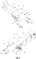
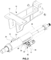
- FIG.1 and FIG. 2 illustrate a steering column 20, and a column bracket 10 which supports the steering column 20.
- the column bracket 10 is fixedly coupled to a vehicle body by a mounting bracket 12 at an upper end portion of the column bracket 10, and supports the steering column 20.
- the telescopic latch apparatus of the steering column may be applied to the steering column having the telescopic function, and may also be applied to a steering column having a tilting function as well as the telescopic function.
- the telescopic latch apparatus has a function of locking and unlocking the telescopic function of the steering column 20.
- a user operates a telescopic lever 14 to the unlocked state to move the steering column 20 in the axial direction
- the restriction to the axial movement of the steering column 20 is removed, such that the telescopic function may be carried out.
- the user operates the telescopic lever 14 to return the telescopic lever 14 back to the locked state, the axial movement of the steering column 20 is restricted, such that the telescopic function is restricted.
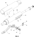
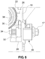
- a first telescopic latch 30 is provided on an outside circumferential surface of the shaft housing 22, and a second telescopic latch 32 is provided on a telescopic bolt 16 and may be fastened to the first telescopic latch 30 by a meshing structure.
- the first telescopic latch 30 has a molding pin 24 formed integrally with an outside circumferential surface of the steering column 20 (the outside circumferential surface of the shaft housing 22).
- the molding pin 24 is integrally or monolithically formed between the shaft housing 22 and the first telescopic latch 30 by injection molding the molding pin 24 after inserting the shaft housing 22 and the first telescopic latch 30 (in a state in which the molding pin is not formed), as insert members, into a mold, and the first telescopic latch 30 is fixed to the outside circumferential surface of the steering column 20 by the molding pin 24.
- the first telescopic latch 30 has an approximately " ⁇ " shaped cross-sectional structure based on the circumferential direction of the shaft housing 22, both end portions of the first telescopic latch 30 in a width direction thereof are in surface-to-surface contact with the outside circumferential surface of the shaft housing 22, and a central portion of the first telescopic latch 30 is integrally connected with the outside circumferential surface of the shaft housing 22 through the molding pin 24.
- the molding pin 24 is formed to protrude radially and perpendicularly from the outside circumferential surface of the shaft housing 22, and integrally connects the first telescopic latch 30 and the shaft housing 22, and one end portion of a curling plate 36 to be described below is inserted into a space between the central portion of the first telescopic latch 30 and the outside circumferential surface of the shaft housing 22.
- first telescopic latch 30 has first gear teeth 31 to be fastened to the second telescopic latch 32.
- the first gear teeth 31 are provided at one side of the first telescopic latch 30 based on the circumferential direction of the shaft housing 22 (e.g., one end portion of the first telescopic latch 30 in the width direction), formed to extend with a predetermined length in the longitudinal direction of the first telescopic latch 30 and the axial direction of the shaft housing 22, and disposed within a predetermined section of the steering column 20, such that a structure in which the first telescopic latch 30 and the second telescopic latch 32 are engaged with each other may be implemented before and after the steering column 20 moves in the axial direction.
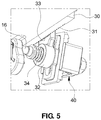
- the second telescopic latch 32 serves to restrict the axial movement of the steering column 20 by being engaged with and fastened to the first telescopic latch 30, second gear teeth 33, which mesh with the first gear teeth 31, are provided at one vertical side of the second telescopic latch 32 (e.g., one vertical end portion of the second telescopic latch 32), and the other vertical side of the second telescopic latch 32 (e.g., the other vertical end portion of the second telescopic latch 32) is fitted with and supported by the telescopic bolt 16.
- the telescopic lever 14 and a fixing nut 17 are coupled to both end portions of the telescopic bolt 16, respectively, in a state in which the telescopic bolt 16 penetrates the column bracket 10, and simultaneously, the telescopic bolt 16 penetrates a lower portion of the outer housing 26 that surrounds the steering column 20, and restricts the axial movement of the outer housing 26.
- the telescopic lever 14, which is coupled to one end portion of the telescopic bolt 16, is provided adjacent to one side of the column bracket 10 with a cam 15 interposed between the telescopic lever 14 and the column bracket 10, and the fixing nut 17, which is coupled to the other end portion of the telescopic bolt 16, is provided adjacent to the other side of the column bracket 10 with a tilt latch device 40 interposed between the fixing nut 17 and the column bracket 10.
- the telescopic bolt 16 has a spring member 34 that provides elastic force to bring the second telescopic latch 32 into close contact with the column bracket 10 (the column bracket 10 and the tilt latch device 40 partially inserted into a hole of the column bracket 10), and the second telescopic latch 32, which is disposed between the spring member 34 and the column bracket 10, is supported by being in close contact with the column bracket 10 by the elastic force of the spring member 34.
- the second telescopic latch 32 is mounted and supported on the column bracket 10 so that the axial movement of the second telescopic latch 32 (in the axial direction of the steering column 20) is restricted.
- the rotation of the second telescopic latch 32 is prevented by the guide hole 28 when the telescopic bolt 16 is linearly moved by the locking operation of the telescopic lever 14, and as a result, the second telescopic latch 32 may normally mesh with the first telescopic latch 30.
- the telescopic lever 14 When the telescopic lever 14 performs the locking operation, the telescopic bolt 16 is linearly moved to one side in a left and right direction by the cam 15, and the second telescopic latch 32 is fastened to the first telescopic latch 30 through the meshing structure, and when the telescopic lever 14 performs the unlocking operation, the telescopic bolt 16 is linearly moved to the other side in the left and right direction by the cam 15, and the second telescopic latch 32 is separated from the first telescopic latch 30.
- the first telescopic latch 30 has the plate-shaped curling plate 36 which is fixedly attached to the outside circumferential surface of the steering column 20 (the outside circumferential surface of the shaft housing), and restricted integrally with the shaft housing 22.
- the curling plate 36 is formed in a plate shape that has a slightly larger length than the first telescopic latch 30, and disposed to be seated on the central portion (which is the part having a space with the outside circumferential surface of the shaft housing 22) of the first telescopic latch 30 based on a radial direction of the shaft housing 22.
- the curling plate 36 is integrally and fixedly attached to the outside circumferential surface of the shaft housing 22 in a state in which one end portion in a longitudinal direction of the curling plate 36 is bent and then inserted into the space between the first telescopic latch 30 and the shaft housing 22.
- the curling plate 36 is restricted as one end portion thereof, which is bent, is integrally attached to the shaft housing 22, and in this case, one end portion of the curling plate 36, which is bent to be caught by an end of the central portion of the first telescopic latch 30, is defined in consideration of a direction of a collision load to be applied at the time of a vehicle collision.
- the curling plate 36 passes through the space between the shaft housing 22 and the first telescopic latch 30 entirely from one end portion of the curling plate 36 (a portion attached to the shaft housing 22) to the other end portion thereof (a portion stacked on the central portion of the first telescopic latch 30).
- the telescopic lever 14 when the telescopic lever 14 is rotated back to the locked state after the position of the axial movement of the steering column 20 is adjusted to the posture of the driver, the telescopic bolt 16 is linearly moved in a direction in which the first telescopic latch 30 and the second telescopic latch 32 mesh with each other, and as a result, the first and second telescopic latches 30 and 32 are fastened by gear meshing, such that the axial movement of the steering column 20 is restricted again.
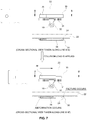
- the molding pin 24 disposed between the shaft housing 22 of the steering column 20 and the first telescopic latch 30 is fractured because the first telescopic latch 30 is in the state of being restricted by the second telescopic latch 32, and the shaft housing 22 is moved in the axial direction toward the vehicle body, as illustrated in FIG. 7 .
- one end portion of the curling plate 36 is integrally moved while being restricted by the shaft housing 22, and as a result, the other end portion of the curling plate 36 is deformed to be bent to pass through the space between the shaft housing 22 and the first telescopic latch 30.
- the amount of absorbed collision load is increased because of the fracture of the molding pin 24 and the deformation of the curling plate 36 during the initial period of the collapse of the steering column 20, and as a result, it is possible to increase the collision load during the initial period of the collapse to a level equal to the collision loads during the middle and late periods after the initial period of the collapse, and in the instant case, it is possible to increase supporting force of the steering column 20 during the initial period of the collapse without increasing a user's operating effort for operating the telescopic lever 14.
- the initial collision load (collapse load) is increased because of fracture force of the molding pin 24 and deforming force of the curling plate 36 as well as the supporting force of the column bracket 10, and as a result, it is possible to absorb collision energy through the supporting force which is maintained at the same level within the entire section where the collapse occurs, and in the instant case, since the effort for operating the telescopic lever 14 is not increased, it is possible to prevent the user from inconvenience by the increase in the operating effort.
- the amount of collision energy initially absorbed at the time of a vehicle collision is increased by increasing the supporting force against the shaft housing 22, which moves in the axial direction, when implementing the telescopic function of the steering column 20. Further, since the amount of absorbed collision energy is increased from the initial period of the collision, the collision energy is relatively uniformly absorbed while the steering column collapses in comparison with the existing case (where the telescopic latch is not applied), uniformly dispersing the collision load.
Landscapes
- Engineering & Computer Science (AREA)
- Chemical & Material Sciences (AREA)
- Combustion & Propulsion (AREA)
- Transportation (AREA)
- Mechanical Engineering (AREA)
- Steering Controls (AREA)
Applications Claiming Priority (1)
| Application Number | Priority Date | Filing Date | Title |
|---|---|---|---|
| KR1020160107528A KR20180022289A (ko) | 2016-08-24 | 2016-08-24 | 자동차 스티어링 컬럼의 텔레스코픽 래치 장치 |
Publications (1)
| Publication Number | Publication Date |
|---|---|
| EP3287340A1 true EP3287340A1 (fr) | 2018-02-28 |
Family
ID=57539170
Family Applications (1)
| Application Number | Title | Priority Date | Filing Date |
|---|---|---|---|
| EP16203262.7A Withdrawn EP3287340A1 (fr) | 2016-08-24 | 2016-12-09 | Appareil de verrouillage télescopique de colonne de direction pour véhicule |
Country Status (4)
| Country | Link |
|---|---|
| US (1) | US10160474B2 (fr) |
| EP (1) | EP3287340A1 (fr) |
| KR (1) | KR20180022289A (fr) |
| CN (1) | CN107776649B (fr) |
Cited By (1)
| Publication number | Priority date | Publication date | Assignee | Title |
|---|---|---|---|---|
| EP3865373A1 (fr) * | 2020-02-14 | 2021-08-18 | Jtekt Corporation | Dispositif de colonne de direction |
Families Citing this family (8)
| Publication number | Priority date | Publication date | Assignee | Title |
|---|---|---|---|---|
| US10654512B2 (en) * | 2017-03-06 | 2020-05-19 | Yamada Manufacturing Co., Ltd. | Steering device |
| KR102541566B1 (ko) * | 2018-04-24 | 2023-06-09 | 에이치엘만도 주식회사 | 자동차 조향컬럼 |
| CN108909822B (zh) * | 2018-06-12 | 2020-05-19 | 吉利汽车研究院(宁波)有限公司 | 一种转向管柱组件的锁止装置、转向管柱组件以及车辆 |
| CN108825763A (zh) * | 2018-06-26 | 2018-11-16 | 吉安汽车配件(苏州)有限公司 | 一种齿轮外壳及其生产方法 |
| KR102728273B1 (ko) * | 2018-12-14 | 2024-11-11 | 에이치엘만도 주식회사 | 자동차의 조향컬럼 |
| KR102517943B1 (ko) * | 2019-09-10 | 2023-04-04 | 에이치엘만도 주식회사 | 자동차 조향컬럼 |
| JP7334644B2 (ja) * | 2020-02-14 | 2023-08-29 | 株式会社ジェイテクト | ステアリングコラム装置 |
| JP7334645B2 (ja) * | 2020-02-14 | 2023-08-29 | 株式会社ジェイテクト | ステアリングコラム装置 |
Citations (5)
| Publication number | Priority date | Publication date | Assignee | Title |
|---|---|---|---|---|
| US20120266716A1 (en) * | 2009-12-16 | 2012-10-25 | Sulser Hansjoerg | Steering column for a motor vehicle |
| WO2015167234A1 (fr) * | 2014-04-28 | 2015-11-05 | 남양공업주식회사 | Colonne de direction |
| WO2016142482A1 (fr) * | 2015-03-12 | 2016-09-15 | Thyssenkrupp Presta Ag | Colonne de direction pour un véhicule automobile |
| WO2017045916A1 (fr) * | 2015-09-16 | 2017-03-23 | Thyssenkrupp Presta Ag | Colonne de direction de véhicule automobile munie d'un dispositif d'absorption de l'énergie de collision |
| WO2018029076A1 (fr) * | 2016-08-09 | 2018-02-15 | Thyssenkrupp Presta Ag | Colonne de direction pour un véhicule automobile |
Family Cites Families (14)
| Publication number | Priority date | Publication date | Assignee | Title |
|---|---|---|---|---|
| JP3517453B2 (ja) | 1994-09-30 | 2004-04-12 | 富士機工株式会社 | 車両用ステアリングコラム |
| US6419269B1 (en) * | 1999-09-20 | 2002-07-16 | Delphi Technologies | Locking system for adjustable position steering column |
| WO2004000627A1 (fr) * | 2002-06-19 | 2003-12-31 | Nsk Ltd. | Unite de colonne de direction amortissant les chocs pour vehicule |
| KR100530030B1 (ko) * | 2003-06-16 | 2005-11-21 | 현대모비스 주식회사 | 자동차용 틸트 스티어링 장치 |
| KR101026119B1 (ko) | 2004-11-13 | 2011-04-05 | 주식회사 만도 | 스티어링 칼럼의 틸팅장치 |
| US20080023952A1 (en) * | 2006-07-31 | 2008-01-31 | Manwaring Marvin V | Adjustable energy absorbing device for a collapsible steering column |
| US7735868B2 (en) * | 2007-02-09 | 2010-06-15 | Gm Global Technology Operations, Inc. | Adjustable steering column assembly for a vehicle |
| KR101028318B1 (ko) | 2008-09-11 | 2011-04-12 | 현대자동차주식회사 | 텔레스코픽 스티어링 칼럼의 장착구조 |
| KR20110096827A (ko) | 2010-02-23 | 2011-08-31 | 남양공업주식회사 | 조정 가능한 스티어링 칼럼을 위한 래치 장치 |
| KR101412191B1 (ko) | 2010-09-08 | 2014-06-25 | 한국델파이주식회사 | 스티어링 칼럼의 텔레스코픽 록킹 구조 |
| KR102053708B1 (ko) * | 2014-02-10 | 2019-12-09 | 남양넥스모 주식회사 | 스티어링 컬럼의 틸팅장치 |
| KR101559821B1 (ko) | 2014-04-28 | 2015-10-15 | 남양공업주식회사 | 스티어링 컬럼 |
| KR101593592B1 (ko) | 2014-10-27 | 2016-02-12 | 남양공업주식회사 | 스티어링 컬럼의 틸팅장치 |
| FR3029489B1 (fr) * | 2014-12-09 | 2018-06-15 | Zf Systemes De Direction Nacam S.A.S. | Mecanisme de colonne de direction ajustable en profondeur a butee escamotable |
-
2016
- 2016-08-24 KR KR1020160107528A patent/KR20180022289A/ko not_active Ceased
- 2016-12-09 EP EP16203262.7A patent/EP3287340A1/fr not_active Withdrawn
- 2016-12-15 CN CN201611163725.8A patent/CN107776649B/zh not_active Expired - Fee Related
-
2017
- 2017-02-01 US US15/421,959 patent/US10160474B2/en active Active
Patent Citations (6)
| Publication number | Priority date | Publication date | Assignee | Title |
|---|---|---|---|---|
| US20120266716A1 (en) * | 2009-12-16 | 2012-10-25 | Sulser Hansjoerg | Steering column for a motor vehicle |
| WO2015167234A1 (fr) * | 2014-04-28 | 2015-11-05 | 남양공업주식회사 | Colonne de direction |
| US20170043802A1 (en) * | 2014-04-28 | 2017-02-16 | Namyang Ind. Co., Ltd | Steering column |
| WO2016142482A1 (fr) * | 2015-03-12 | 2016-09-15 | Thyssenkrupp Presta Ag | Colonne de direction pour un véhicule automobile |
| WO2017045916A1 (fr) * | 2015-09-16 | 2017-03-23 | Thyssenkrupp Presta Ag | Colonne de direction de véhicule automobile munie d'un dispositif d'absorption de l'énergie de collision |
| WO2018029076A1 (fr) * | 2016-08-09 | 2018-02-15 | Thyssenkrupp Presta Ag | Colonne de direction pour un véhicule automobile |
Cited By (2)
| Publication number | Priority date | Publication date | Assignee | Title |
|---|---|---|---|---|
| EP3865373A1 (fr) * | 2020-02-14 | 2021-08-18 | Jtekt Corporation | Dispositif de colonne de direction |
| US11325636B2 (en) | 2020-02-14 | 2022-05-10 | Jtekt Corporation | Steering column device |
Also Published As
| Publication number | Publication date |
|---|---|
| US10160474B2 (en) | 2018-12-25 |
| CN107776649A (zh) | 2018-03-09 |
| KR20180022289A (ko) | 2018-03-06 |
| CN107776649B (zh) | 2021-07-09 |
| US20180057036A1 (en) | 2018-03-01 |
Similar Documents
| Publication | Publication Date | Title |
|---|---|---|
| US10160474B2 (en) | Telescopic latch apparatus of steering column for vehicle | |
| CN108688713B (zh) | 用于车辆的电机驱动转向柱装置 | |
| US9428214B2 (en) | Steering column for vehicle | |
| EP2933133B1 (fr) | Dispositif coulissant pour siège de véhicule | |
| US20160272235A1 (en) | Steering apparatus | |
| US10913483B2 (en) | Damper assembly for steering column | |
| US9446795B2 (en) | Structure for reinforcing front vehicle body | |
| KR20160106236A (ko) | 자동차의 조향컬럼 | |
| US20200189422A1 (en) | Seat track mechanism for vehicle | |
| US8613341B2 (en) | Protective device of automobile driver | |
| US10703346B2 (en) | Brake pedal apparatus for vehicle | |
| US20180208232A1 (en) | Steering column | |
| KR102267717B1 (ko) | 조향컬럼용 틸트 구조체 | |
| US9256242B2 (en) | Driver's injury prevention type pedal | |
| US10239488B2 (en) | Column housing for vehicle steering system | |
| EP2228282B1 (fr) | Structure de chemise de colonne de direction | |
| US9352672B2 (en) | Inertial latch system for a vehicle seat | |
| US20180015953A1 (en) | Vehicle front portion structure | |
| CN220410371U (zh) | 头枕总成和座椅 | |
| JP6006882B2 (ja) | アシストグリップ | |
| JP2010173631A (ja) | 積載空間カバー、及び自動車 | |
| KR20190036170A (ko) | 스티어링 컬럼의 충격흡수 구조 | |
| EP4017782A1 (fr) | Verrou à enclenchement télescopique de colonne de direction et dispositif de libération | |
| US12312002B1 (en) | Bi-directional lock mechanism for steering column | |
| CN116494850B (zh) | 头枕总成和座椅 |
Legal Events
| Date | Code | Title | Description |
|---|---|---|---|
| PUAI | Public reference made under article 153(3) epc to a published international application that has entered the european phase |
Free format text: ORIGINAL CODE: 0009012 |
|
| AK | Designated contracting states |
Kind code of ref document: A1 Designated state(s): AL AT BE BG CH CY CZ DE DK EE ES FI FR GB GR HR HU IE IS IT LI LT LU LV MC MK MT NL NO PL PT RO RS SE SI SK SM TR |
|
| AX | Request for extension of the european patent |
Extension state: BA ME |
|
| 17P | Request for examination filed |
Effective date: 20180828 |
|
| RBV | Designated contracting states (corrected) |
Designated state(s): AL AT BE BG CH CY CZ DE DK EE ES FI FR GB GR HR HU IE IS IT LI LT LU LV MC MK MT NL NO PL PT RO RS SE SI SK SM TR |
|
| 17Q | First examination report despatched |
Effective date: 20181114 |
|
| STAA | Information on the status of an ep patent application or granted ep patent |
Free format text: STATUS: THE APPLICATION IS DEEMED TO BE WITHDRAWN |
|
| 18D | Application deemed to be withdrawn |
Effective date: 20190326 |