EP3287343B1 - Lenksteuerungsvorrichtung - Google Patents
Lenksteuerungsvorrichtung Download PDFInfo
- Publication number
- EP3287343B1 EP3287343B1 EP17186504.1A EP17186504A EP3287343B1 EP 3287343 B1 EP3287343 B1 EP 3287343B1 EP 17186504 A EP17186504 A EP 17186504A EP 3287343 B1 EP3287343 B1 EP 3287343B1
- Authority
- EP
- European Patent Office
- Prior art keywords
- current
- value
- processing portion
- magnitude
- command value
- Prior art date
- Legal status (The legal status is an assumption and is not a legal conclusion. Google has not performed a legal analysis and makes no representation as to the accuracy of the status listed.)
- Active
Links
Images



Classifications
-
- B—PERFORMING OPERATIONS; TRANSPORTING
- B62—LAND VEHICLES FOR TRAVELLING OTHERWISE THAN ON RAILS
- B62D—MOTOR VEHICLES; TRAILERS
- B62D5/00—Power-assisted or power-driven steering
- B62D5/04—Power-assisted or power-driven steering electrical, e.g. using an electric servo-motor connected to, or forming part of, the steering gear
- B62D5/0457—Power-assisted or power-driven steering electrical, e.g. using an electric servo-motor connected to, or forming part of, the steering gear characterised by control features of the drive means as such
- B62D5/046—Controlling the motor
-
- B—PERFORMING OPERATIONS; TRANSPORTING
- B62—LAND VEHICLES FOR TRAVELLING OTHERWISE THAN ON RAILS
- B62D—MOTOR VEHICLES; TRAILERS
- B62D5/00—Power-assisted or power-driven steering
- B62D5/04—Power-assisted or power-driven steering electrical, e.g. using an electric servo-motor connected to, or forming part of, the steering gear
- B62D5/0457—Power-assisted or power-driven steering electrical, e.g. using an electric servo-motor connected to, or forming part of, the steering gear characterised by control features of the drive means as such
- B62D5/046—Controlling the motor
- B62D5/0469—End-of-stroke control
-
- B—PERFORMING OPERATIONS; TRANSPORTING
- B62—LAND VEHICLES FOR TRAVELLING OTHERWISE THAN ON RAILS
- B62D—MOTOR VEHICLES; TRAILERS
- B62D3/00—Steering gears
- B62D3/02—Steering gears mechanical
- B62D3/12—Steering gears mechanical of rack-and-pinion type
-
- B—PERFORMING OPERATIONS; TRANSPORTING
- B62—LAND VEHICLES FOR TRAVELLING OTHERWISE THAN ON RAILS
- B62D—MOTOR VEHICLES; TRAILERS
- B62D5/00—Power-assisted or power-driven steering
- B62D5/04—Power-assisted or power-driven steering electrical, e.g. using an electric servo-motor connected to, or forming part of, the steering gear
- B62D5/0457—Power-assisted or power-driven steering electrical, e.g. using an electric servo-motor connected to, or forming part of, the steering gear characterised by control features of the drive means as such
- B62D5/046—Controlling the motor
- B62D5/0463—Controlling the motor calculating assisting torque from the motor based on driver input
Definitions
- An aspect of the invention relates to a steering control device configured to control a steering system including a turning actuator that turns steered wheels of a vehicle.
- the steering system assists turning of the steered wheels in accordance with steering of a steering wheel.
- the turning actuator includes a motor.
- the steering control device includes a feedback processing portion configured to control through feedback a current flowing through the motor to a current command value; an end determination processing portion configured to determine whether a turning angle of steered wheels has reached a limit angle determined by a structure of the steering system; and an end-time limit processing portion configured to limit a magnitude of the current command value for the motor to a magnitude of a limited current value or smaller, when the end determination processing portion determines that the turning angle has reached the limit angle.
- the magnitude of the required steering torque is small. Accordingly, the magnitude of the steering torque is less likely to be significantly increased.
- the magnitude of the steering torque tends to be abruptly increased as compared to the magnitude of the steering torque before the turning angle reaches the limit angle.
- the current immediately before the turning angle reaches the limit angle is estimated on the basis of the detected value and so on at the time when the tentative determination processing portion determines that the turning angle has reached the limit angle.
- the current immediately before the turning angle reaches the limit angle can be accurately estimated.
- the end-time limit processing portion executes the processing of limiting the magnitude of the current command value to the magnitude of the current estimated by the estimation processing portion or smaller, when the main determination processing portion determines that the turning angle has reached the limit angle.
- the gain of the integral element is increased when the processing of limiting the magnitude of the current command value for the motor to the magnitude of the limited current value or smaller is executed, that is, when the magnitude of the induced voltage is abruptly decreased.
- the control of decreasing the magnitude of the voltage is delayed with respect to the decrease in the magnitude of the induced voltage.
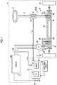
- the first rack and pinion mechanism 20 includes a rack shaft 30 and the pinion shaft 22 that are arranged at a specified crossing angle, and first rack teeth 32a formed on the rack shaft 30 mesh with pinion teeth 22a formed on the pinion shaft 22. Note that steered wheels 34 are respectively coupled to both ends of the rack shaft 30 via tie rods.
- the second rack and pinion mechanism 40 includes the rack shaft 30 and a pinion shaft 42 that are arranged at a specified crossing angle, and second rack teeth 34a formed on the rack shaft 30 mesh with pinion teeth 42a formed on the pinion shaft 42.
- a current command value setting processing portion M12 sets a current command value iq0* of a q-axis on the basis of the assist command value Trqa*.
- the current command value setting processing portion M12 sets a magnitude (an absolute value) of the current command value iq0* to a larger value as the magnitude of the assist command value Trqa* is increased.
- a sign of the current command value iq0* is a positive sign when the current command value iq0* has a value on the right turn side.
- An upper limit guard processing portion M14 performs upper limit guard processing such that the absolute value of the current command value iq0* of the q-axis becomes equal to or lower than an upper limit guard value Ith.
- the upper limit guard value Ith is set to a smaller value than that when the magnitude of the rotational speed ⁇ is small.
- a three-phase conversion processing portion M28 converts the voltage command values vd*, vq* of the d, q-axes to voltage command values vu*, vv*, vw* in a three-phase fixed coordinate system.
- An operation signal generation processing portion M30 generates and outputs an operation signal MS for the inverter 60 such that an output line voltage of the inverter 60 coincides with an interphase voltage determined by the voltage command values vu*, vv*, vw*.
- a rotational speed computation processing portion M32 computes the rotational speed ⁇ of the rotational shaft 52 of the motor 50 on the basis of the rotational angle ⁇ .
- An acceleration computation processing portion M34 computes a changing rate (angular acceleration d ⁇ ) of the rotational speed ⁇ on the basis of the rotational speed ⁇ .
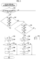
- the CPU 72 first obtains the current iq of the q-axis, the current command value iq1*, the rotational speed ⁇ , and the latest value d ⁇ (n) of the angular acceleration d ⁇ (S10).
- the angular acceleration d ⁇ is described as "d ⁇ (n)" to indicate that it is the latest value.
- the latest values of the current iq of the q-axis, the current command value iq1*, and the rotational speed ⁇ are also obtained.
- a condition (a1) is a condition that the angular acceleration d ⁇ (n - 1) obtained in the processing of step S10 in the last control period before the series of the processing shown in FIG. 3 is equal to or higher than a tentative determination acceleration threshold d ⁇ th1.
- the tentative determination acceleration threshold d ⁇ th1 is set to a negative value that is a value at the time when the magnitude of the rotational speed ⁇ is decreased.
- a condition (b1) is a condition that the angular acceleration d ⁇ (n) obtained in the processing of step S10 is lower than the tentative determination acceleration threshold d ⁇ th1.
- an absolute value of "Kie ⁇ d ⁇ (n)" is an estimated value of an increase amount by which an absolute value of the current iq of the q-axis is increased by the end abutment. That is, due to the end abutment, the magnitude of the rotational speed ⁇ is abruptly decreased, and a magnitude of an induced voltage of the motor 50 is abruptly decreased.
- resistance R, an inductance L, an induced voltage constant ⁇ , and a differential operator p of the motor 50 are used, a relationship expressed by the following expression (c1) is established between the current iq of the q-axis and a voltage vq of the q-axis.
- vq R ⁇ iq + ⁇ ⁇ L ⁇ id + p ⁇ Lq ⁇ iq + ⁇ ⁇ ⁇
- the constant Kie is set to a small value with a margin such that a magnitude of "iq + Kie ⁇ d ⁇ (n)" does not become smaller than the magnitude of the current iq of the q-axis immediately before the end abutment.
- a condition (c2) is a condition that the rotational speed ⁇ is lower than "(-1) ⁇ ⁇ th1".
- the conditions (a2), (b2), (c2) respectively correspond to the above conditions (a1), (b1), (c1).
- the CPU 72 When determining that the value of the right turning counter Cp is equal to or larger than the threshold Cth (S38: YES), the CPU 72 initializes the right turning counter Cp (S40) and sets the end abutment determination flag F to "1" (S42). When determining that the logical conjunction of the above conditions (d1), (e1), (f1), (g1) is false (S32: NO), the CPU 72 determines whether logical conjunction of the following conditions (d2), (e2), (f2), (g2) is true (S46). This processing is executed to determine whether the end abutment has occurred by turning the steering wheel 12 to the left turn side.
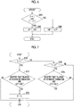
- FIG. 6 shows a procedure of processing executed by the switching processing portion M16 shown in FIG. 2 .
- the processing shown in FIG. 6 is repeatedly executed at specified intervals, for example.
- the CPU 72 executes the processing.
- the CPU 72 determines whether the end abutment determination flag F is "1" (S70). When determining that the end abutment determination flag F is "1" (S70: YES), the CPU 72 determines whether logical conjunction of a condition that specified time T elapses after the end abutment main determination (i.e., after the main determination that the end abutment has occurred is made) and a condition that the current command value iq1* output by the upper limit guard processing portion M14 is equal to or smaller than the end-time current command value iqth is true (S72).
- the condition that the current command value iq1* is equal to or larger than the end-time current command value iqth is a condition that the absolute value of the current command value iq1* is equal to or smaller than the absolute value of the end-time current command value iqth. Then, when determining that the logical conjunction is true (S78: YES), the CPU 72 sets the end abutment determination flag F to "0" (S74).
- a feedback gain of the q-axis feedback processing portion M22 is set to be variable based on whether the end abutment has occurred.
- FIG. 9 shows a procedure of variable setting processing for the feedback gain.
- the processing shown in FIG. 9 is realized as processing executed by the q-axis feedback processing portion M22 when the CPU 72 executes the program stored in the memory 74. Note that the processing shown in FIG. 9 is repeatedly executed at specified intervals, for example.
- the current control is not limited to the control that sets the voltage command value vq* of the q-axis as a feedback manipulative variable of the q-axis.
- the voltage command value vq* of the q-axis may be set as a sum of the feedback manipulative variable of the q-axis and an open-loop manipulative variable " ⁇ ⁇ L ⁇ id" in the decoupling control.
- the voltage command value vq* of the q-axis may be set as a sum of the feedback manipulative variable of the q-axis, the open-loop manipulative variable in the decoupling control, and an open-loop manipulative variable " ⁇ ⁇ ⁇ " corresponding to the induced voltage.
- the steering system is not limited to the steering system in which the rotational angle (the steering angle) of the steering wheel 12 corresponds to the turning angle of the steered wheels 34 on one-to-one basis.
- the steering system may include a steering angle ratio variable actuator, and may be configured such that the steering angle ratio can be changed by electronic control, the steering angle ratio being a ratio between the steering angle and the turning angle.
Landscapes
- Engineering & Computer Science (AREA)
- Chemical & Material Sciences (AREA)
- Combustion & Propulsion (AREA)
- Transportation (AREA)
- Mechanical Engineering (AREA)
- Steering Control In Accordance With Driving Conditions (AREA)
- Power Steering Mechanism (AREA)
Claims (6)
- Lenksteuerungsvorrichtung (70), die konfiguriert ist, um ein Lenksystem (10) zu steuern, das ein Drehstellglied (PSA) umfasst, das gelenkte Räder (34) eines Fahrzeugs dreht, wobei das Lenksystem (10) ein Drehen der gelenkten Räder (34) in Übereinstimmung mit einem Lenken eines Lenkrads (12) unterstützt, wobei das Drehstellglied (PSA) einen Motor (50) umfasst, wobei die Lenksteuerungsvorrichtung (70) aufweist:einen Rückkopplungs-Verarbeitungsabschnitt (M22), der konfiguriert ist, um durch Rückkopplung einen Strom (iq), der durch den Motor (50) fließt, zu einem Strombefehlswert (iq*) zu steuern;einen Endbestimmungs-Verarbeitungsabschnitt (72), der konfiguriert ist, um zu bestimmen, ob ein Drehwinkel von gelenkten Rädern (34) einen durch eine Struktur des Lenksystems (10) bestimmten Grenzwinkel erreicht hat; undeinen Endzeitbegrenzungs-Verarbeitungsabschnitt (72), der konfiguriert ist, um eine Größe des Strombefehlswerts (iq*) für den Motor (50) auf eine Größe eines begrenzten Stromwerts oder kleiner zu begrenzen (S62), wenn der Endbestimmungs-Verarbeitungsabschnitt (72) bestimmt, dass der Drehwinkel den Grenzwinkel erreicht hat, dadurch gekennzeichnet, dassder begrenzte Stromwert ein Wert ist, der durch Ausführen einer Korrektur erhalten wird, um eine Größe eines erfassten Werts des Stroms (iq), der durch den Motor (50) fließt, zu einem Zeitpunkt zu verringern, wenn der Endbestimmungs-Verarbeitungsabschnitt (72) bestimmt, dass der Drehwinkel den Grenzwinkel erreicht hat, basierend auf einem Grad einer Verringerung einer Größe einer Drehzahl (ω) des Motors (50).
- Lenksteuerungsvorrichtung (70) nach Anspruch 1, wobei:die Lenksteuerungsvorrichtung (70) ferner einen Befehlswert-Einstellverarbeitungsabschnitt (M10, M12, M14) umfasst, der konfiguriert ist, um den Strombefehlswert (iq*) basierend auf einem erfassten Wert des Lenkmoments (Trq) einzustellen;der Befehlswert-Einstellverarbeitungsabschnitt konfiguriert ist, um die Größe des Strombefehlswerts (iq*) derart einzustellen, dass die Größe des Strombefehlswerts (iq*) zu einem Zeitpunkt, wenn eine Größe des erfassten Wertes des Lenkmoments (Trq) groß ist, größer ist als die Größe des Strombefehlswerts (iq*) zu einem Zeitpunkt, wenn die Größe des erfassten Wertes des Lenkmoments (Trq) klein ist;die Lenksteuerungsvorrichtung (70) ferner einen Schätzverarbeitungsabschnitt (72) umfasst, der konfiguriert ist, um unmittelbar bevor der Drehwinkel den Grenzwinkel erreicht den durch den Motor (50) fließenden Strom derart zu schätzen, dass der geschätzte Strom (iqth) einer von dem Strombefehlswert (iq1*), der durch den Befehlswert-Einstellverarbeitungsabschnitt (M10, M12, M14) eingestellt wird, und dem begrenzten Stromwert ist, wenn der Endbestimmungs-Verarbeitungsabschnitt (72) bestimmt, dass der Drehwinkel den Grenzwinkel erreicht hat, wobei die Größe der einen von dem Strombefehlswert (iq1*) und dem begrenzten Stromwert kleiner ist als die des anderen; undder Endzeitbegrenzungs-Verarbeitungsabschnitt (72) konfiguriert ist, um den Strombefehlswert (iq*) auf einen Wert zu setzen (S62), der gleich oder kleiner als eine Größe des Stroms (iqth) ist, der durch den Schätzverarbeitungsabschnitt (72) geschätzt wird.
- Lenksteuerungsvorrichtung (70) nach Anspruch 2, wobei
der Befehlswert-Einstellverarbeitungsabschnitt (M10, M12, M14) einen Obergrenzenschutz-Verarbeitungsabschnitt (M14) umfasst, der konfiguriert ist, um eine Obergrenzenschutzverarbeitung an der Größe des Strombefehlswerts (iq*) auszuführen;
der Obergrenzenschutz-Verarbeitungsabschnitt (M14) konfiguriert ist, um einen Obergrenzenschutzwert (Ith) des Strombefehlswerts (iq*) derart einzustellen, dass der Obergrenzenschutzwert (Ith) zu einem Zeitpunkt, wenn die Größe der Drehzahl (ω) des Motors (50) groß ist, kleiner ist als der Oberengrenzschutzwert (Ith) zu einem Zeitpunkt, wenn die Größe der Drehzahl (ω) des Motors (50) klein ist; und
der Schätzverarbeitungsabschnitt (72) konfiguriert ist, um unmittelbar bevor der Drehwinkel den Grenzwinkel erreicht den durch den Motor (50) fließenden Strom derart zu schätzen, dass der geschätzte Strom (iqth) einer von dem Strombefehlswert (iq1*), der der Obergrenzenschutzverarbeitung unterworfen ist, und dem begrenzten Stromwert ist, wobei die Größe des einen des Strombefehlswerts (iq1*) und des begrenzten Stromwerts kleiner als die des anderen ist. - Lenksteuerungsvorrichtung (70) nach Anspruch 2 oder 3, wobei:der Endbestimmungs-Verarbeitungsabschnitt (72) einen vorläufigen BestimmungsVerarbeitungsabschnitt (72), der konfiguriert ist, um eine vorläufige Bestimmung vorzunehmen, dass der Drehwinkel den Grenzwinkel erreicht hat, und einen Hauptbestimmungs-Verarbeitungsabschnitt (72) umfasst, der konfiguriert ist, um eine Hauptbestimmung auszuführen, dass der Drehwinkel den Grenzwinkel erreicht hat;eine Bedingung, basierend auf der der Hauptbestimmungs-Verarbeitungsabschnitt (72) bestimmt, dass der Drehwinkel den Grenzwinkel erreicht hat, eine strengere Bedingung als eine Bedingung ist, basierend auf der der vorläufige Bestimmungsverarbeitungsabschnitt bestimmt, dass der Drehwinkel den Grenzwinkel erreicht hat;der Schätzverarbeitungsabschnitt (72) konfiguriert ist, um unmittelbar bevor der Drehwinkel den Grenzwinkel erreicht den durch den Motor (50) fließenden Strom derart zu schätzen, dass der geschätzte Strom (iqth) einer von dem begrenzten Stromwert und dem Strombefehlswert (iq1*) zu einem Zeitpunkt ist, wenn der vorläufige Bestimmungsverarbeitungsabschnitt bestimmt, dass der Drehwinkel den Grenzwinkel erreicht hat, wobei die Größe des einen des begrenzten Stromwerts und des Strombefehlswerts (iq1*) kleiner als die des anderen ist, und der begrenzte Stromwert ein Wert ist, der durch Ausführen einer Korrektur erhalten wird, um die Größe des erfassten Werts des Stroms (iq), der durch den Motor (50) fließt, zu dem Zeitpunkt zu verringern, wenn der vorläufige Bestimmungsverarbeitungsabschnitt bestimmt, dass der Drehwinkel den Grenzwinkel erreicht hat, basierend auf dem Grad der Verringerung der Größe der Drehzahl (ω) des Motors (50); undder Endzeitbegrenzungs-Verarbeitungsabschnitt (72) konfiguriert ist, um die Größe des Strombefehlswerts (iq*) für den Motor (50) auf die Größe des Stroms (iqth), der durch den Schätzverarbeitungsabschnitt (72) geschätzt wird, oder kleiner zu begrenzen, wenn der Hauptbestimmungs-Verarbeitungsabschnitt (72) bestimmt, dass der Drehwinkel den Grenzwinkel erreicht hat.
- Lenksteuerungsvorrichtung (70) nach einem der Ansprüche 2 bis 4, wobei
der Rückkopplungs-Verarbeitungsabschnitt (M22) konfiguriert ist, um eine Spannung (vq*), die an den Motor (50) angelegt wird, basierend auf einem Ausgangswert eines integralen Elements zu steuern, das unter Verwendung einer Differenz zwischen dem durch den Motor (50) fließenden Strom (iq) und dem Strombefehlswert (iq*) als ein Eingang erhalten wird; und
der Endzeitbegrenzungs-Verarbeitungsabschnitt (72) konfiguriert ist, um den Strombefehlswert (iq*) auf einen Wert einzustellen (S62), der durch Ausführen einer Korrektur erhalten wird, um die Größe des durch den Schätzverarbeitungsabschnitt (72) geschätzten Stroms (iqth) zu verringern, basierend auf dem Grad der Verringerung der Größe der Drehzahl (ω) des Motors (50). - Lenksteuerungsvorrichtung (70) nach einem der Ansprüche 1 bis 5, wobei
der Rückkopplungs-Verarbeitungsabschnitt (M22) konfiguriert ist, um eine Spannung (vq*), die an den Motor (50) angelegt wird, basierend auf einem Ausgangswert eines integralen Elements zu steuern, das unter Verwendung einer Differenz zwischen dem durch den Motor (50) fließenden Strom (iq) und dem Strombefehlswert (iq*) als ein Eingang erhalten wird; und
wenn der Endzeitbegrenzungs-Verarbeitungsabschnitt (72) eine Verarbeitung zum Begrenzen der Größe des Strombefehlswerts (iq*) für den Motor (50) auf die Größe des begrenzten Stromwerts oder kleiner ausführt, der Rückkopplungs-Verarbeitungsabschnitt (M22) eine Verstärkung (Ki) des integralen Elements größer als die (Ki0) macht, wenn der Endzeitbegrenzungs-Verarbeitungsabschnitt (72) die Verarbeitung nicht ausführt.
Applications Claiming Priority (1)
| Application Number | Priority Date | Filing Date | Title |
|---|---|---|---|
| JP2016165884A JP6701032B2 (ja) | 2016-08-26 | 2016-08-26 | 操舵制御装置 |
Publications (3)
| Publication Number | Publication Date |
|---|---|
| EP3287343A2 EP3287343A2 (de) | 2018-02-28 |
| EP3287343A3 EP3287343A3 (de) | 2018-10-10 |
| EP3287343B1 true EP3287343B1 (de) | 2019-09-25 |
Family
ID=59649545
Family Applications (1)
| Application Number | Title | Priority Date | Filing Date |
|---|---|---|---|
| EP17186504.1A Active EP3287343B1 (de) | 2016-08-26 | 2017-08-16 | Lenksteuerungsvorrichtung |
Country Status (4)
| Country | Link |
|---|---|
| US (1) | US20180057043A1 (de) |
| EP (1) | EP3287343B1 (de) |
| JP (1) | JP6701032B2 (de) |
| CN (1) | CN107776657B (de) |
Families Citing this family (9)
| Publication number | Priority date | Publication date | Assignee | Title |
|---|---|---|---|---|
| JP7014029B2 (ja) * | 2018-04-20 | 2022-02-15 | 株式会社デンソー | ステアリング制御装置 |
| CN111086553B (zh) * | 2018-10-24 | 2022-03-11 | 蜂巢智能转向系统(江苏)有限公司 | 齿条末端保护方法、装置及电动助力转向系统 |
| JP7280099B2 (ja) * | 2019-04-19 | 2023-05-23 | 株式会社ジェイテクト | モータの制御システム、およびモータの制御装置 |
| JP7376290B2 (ja) | 2019-09-10 | 2023-11-08 | 株式会社ジェイテクト | 操舵制御装置 |
| JP7290529B2 (ja) * | 2019-09-26 | 2023-06-13 | 株式会社ジェイテクト | 操舵制御装置 |
| US11724732B2 (en) * | 2019-09-26 | 2023-08-15 | Jtekt Corporation | Steering control device |
| JP7339104B2 (ja) * | 2019-09-26 | 2023-09-05 | 株式会社ジェイテクト | 操舵制御装置 |
| CN110626423B (zh) * | 2019-09-27 | 2021-09-14 | 成都坦途智行科技有限公司 | 一种无人车线控转向系统及其工作方法 |
| DE102022107761A1 (de) * | 2022-04-01 | 2023-10-05 | Hamm Ag | Verfahren zum Betreiben einer Bodenbearbeitungsmaschine |
Family Cites Families (14)
| Publication number | Priority date | Publication date | Assignee | Title |
|---|---|---|---|---|
| JP4319112B2 (ja) * | 2004-08-27 | 2009-08-26 | 三菱電機株式会社 | 電動パワーステアリング装置 |
| JP4289458B2 (ja) * | 2004-09-07 | 2009-07-01 | 三菱電機株式会社 | 電動パワーステアリング制御装置 |
| JP4682836B2 (ja) * | 2005-10-20 | 2011-05-11 | トヨタ自動車株式会社 | 車両の操舵装置 |
| JP4449918B2 (ja) * | 2006-02-15 | 2010-04-14 | トヨタ自動車株式会社 | 電動パワーステアリング装置 |
| JP2008137486A (ja) * | 2006-12-01 | 2008-06-19 | Jtekt Corp | 電動パワーステアリング装置 |
| JP2008143200A (ja) * | 2006-12-06 | 2008-06-26 | Nsk Ltd | 電動パワーステアリング装置 |
| JP2009143312A (ja) | 2007-12-12 | 2009-07-02 | Toyota Motor Corp | 電動パワーステアリング装置 |
| JP5292995B2 (ja) * | 2008-08-22 | 2013-09-18 | 株式会社ジェイテクト | モータ制御装置及び電動パワーステアリング装置 |
| CN103987614B (zh) * | 2011-12-22 | 2016-04-13 | 日产自动车株式会社 | 车辆的转向控制装置和转向控制方法 |
| CN103863392B (zh) * | 2012-12-12 | 2017-06-06 | 上海汽车集团股份有限公司 | 一种抑制汽车侧翻的控制方法和电动助力转向装置 |
| CN105339240B (zh) * | 2013-10-01 | 2017-02-22 | 日本精工株式会社 | 电动助力转向装置 |
| JP2015085729A (ja) * | 2013-10-28 | 2015-05-07 | 株式会社ショーワ | 電動パワーステアリング装置 |
| CN104354760B (zh) * | 2014-11-04 | 2017-12-22 | 广西柳工机械股份有限公司 | 非接触式转向限位的比例控制系统及比例控制方法 |
| JP6004141B1 (ja) * | 2014-12-25 | 2016-10-05 | 日本精工株式会社 | 電動パワーステアリング装置 |
-
2016
- 2016-08-26 JP JP2016165884A patent/JP6701032B2/ja not_active Expired - Fee Related
-
2017
- 2017-08-11 US US15/674,834 patent/US20180057043A1/en not_active Abandoned
- 2017-08-15 CN CN201710697718.4A patent/CN107776657B/zh active Active
- 2017-08-16 EP EP17186504.1A patent/EP3287343B1/de active Active
Non-Patent Citations (1)
| Title |
|---|
| None * |
Also Published As
| Publication number | Publication date |
|---|---|
| JP2018030532A (ja) | 2018-03-01 |
| EP3287343A3 (de) | 2018-10-10 |
| JP6701032B2 (ja) | 2020-05-27 |
| EP3287343A2 (de) | 2018-02-28 |
| US20180057043A1 (en) | 2018-03-01 |
| CN107776657B (zh) | 2021-05-11 |
| CN107776657A (zh) | 2018-03-09 |
Similar Documents
| Publication | Publication Date | Title |
|---|---|---|
| EP3287343A2 (de) | Lenksteuerungsvorrichtung | |
| US7663330B2 (en) | Electric power steering device, and control method thereof | |
| US8874316B2 (en) | Vehicle steering system | |
| JP5453714B2 (ja) | モータ制御装置および電動パワーステアリング装置 | |
| CN105229917B (zh) | 永磁体型同步电动机的磁极位置检测装置 | |
| EP3287342B1 (de) | Lenksteuerungsvorrichtung | |
| US9199665B2 (en) | Electric power steering system | |
| WO2011077589A1 (ja) | 電動パワーステアリング装置 | |
| JP5262931B2 (ja) | 電動パワーステアリング装置 | |
| JP2008189225A (ja) | 電動パワーステアリング装置の制御装置 | |
| EP2015443A1 (de) | Motorsteuervorrichtung | |
| JP2004042691A (ja) | 電動パワーステアリング装置 | |
| EP3159242A2 (de) | Lenksteuerungsvorrichtung | |
| JP2010029030A (ja) | モータ制御装置 | |
| JP2012166776A (ja) | 電動パワーステアリング装置 | |
| JP5252190B2 (ja) | モータ制御装置 | |
| US10965234B2 (en) | Motor controller and electric power steering device having same | |
| JP2009254112A (ja) | 回転機の角度推定装置 | |
| JP5392530B2 (ja) | モータ制御装置 | |
| JP2011218878A (ja) | 電動パワーステアリング装置 | |
| JP5257374B2 (ja) | 電動パワーステアリング装置 | |
| EP3495235A1 (de) | Lenksteuerungseinheit | |
| JP6394885B2 (ja) | 電動パワーステアリング装置 | |
| CN111267944B (zh) | 转向控制器和转向控制方法 | |
| JP4736116B2 (ja) | 電動パワーステアリング制御装置、および方法 |
Legal Events
| Date | Code | Title | Description |
|---|---|---|---|
| PUAI | Public reference made under article 153(3) epc to a published international application that has entered the european phase |
Free format text: ORIGINAL CODE: 0009012 |
|
| STAA | Information on the status of an ep patent application or granted ep patent |
Free format text: STATUS: THE APPLICATION HAS BEEN PUBLISHED |
|
| AK | Designated contracting states |
Kind code of ref document: A2 Designated state(s): AL AT BE BG CH CY CZ DE DK EE ES FI FR GB GR HR HU IE IS IT LI LT LU LV MC MK MT NL NO PL PT RO RS SE SI SK SM TR |
|
| AX | Request for extension of the european patent |
Extension state: BA ME |
|
| PUAL | Search report despatched |
Free format text: ORIGINAL CODE: 0009013 |
|
| AK | Designated contracting states |
Kind code of ref document: A3 Designated state(s): AL AT BE BG CH CY CZ DE DK EE ES FI FR GB GR HR HU IE IS IT LI LT LU LV MC MK MT NL NO PL PT RO RS SE SI SK SM TR |
|
| AX | Request for extension of the european patent |
Extension state: BA ME |
|
| RIC1 | Information provided on ipc code assigned before grant |
Ipc: B62D 5/04 20060101AFI20180901BHEP |
|
| STAA | Information on the status of an ep patent application or granted ep patent |
Free format text: STATUS: REQUEST FOR EXAMINATION WAS MADE |
|
| 17P | Request for examination filed |
Effective date: 20190319 |
|
| RBV | Designated contracting states (corrected) |
Designated state(s): AL AT BE BG CH CY CZ DE DK EE ES FI FR GB GR HR HU IE IS IT LI LT LU LV MC MK MT NL NO PL PT RO RS SE SI SK SM TR |
|
| GRAP | Despatch of communication of intention to grant a patent |
Free format text: ORIGINAL CODE: EPIDOSNIGR1 |
|
| STAA | Information on the status of an ep patent application or granted ep patent |
Free format text: STATUS: GRANT OF PATENT IS INTENDED |
|
| INTG | Intention to grant announced |
Effective date: 20190506 |
|
| GRAS | Grant fee paid |
Free format text: ORIGINAL CODE: EPIDOSNIGR3 |
|
| GRAA | (expected) grant |
Free format text: ORIGINAL CODE: 0009210 |
|
| STAA | Information on the status of an ep patent application or granted ep patent |
Free format text: STATUS: THE PATENT HAS BEEN GRANTED |
|
| AK | Designated contracting states |
Kind code of ref document: B1 Designated state(s): AL AT BE BG CH CY CZ DE DK EE ES FI FR GB GR HR HU IE IS IT LI LT LU LV MC MK MT NL NO PL PT RO RS SE SI SK SM TR |
|
| REG | Reference to a national code |
Ref country code: GB Ref legal event code: FG4D |
|
| REG | Reference to a national code |
Ref country code: CH Ref legal event code: EP |
|
| REG | Reference to a national code |
Ref country code: AT Ref legal event code: REF Ref document number: 1183553 Country of ref document: AT Kind code of ref document: T Effective date: 20191015 |
|
| REG | Reference to a national code |
Ref country code: IE Ref legal event code: FG4D |
|
| REG | Reference to a national code |
Ref country code: DE Ref legal event code: R096 Ref document number: 602017007266 Country of ref document: DE |
|
| REG | Reference to a national code |
Ref country code: NL Ref legal event code: MP Effective date: 20190925 |
|
| PG25 | Lapsed in a contracting state [announced via postgrant information from national office to epo] |
Ref country code: SE Free format text: LAPSE BECAUSE OF FAILURE TO SUBMIT A TRANSLATION OF THE DESCRIPTION OR TO PAY THE FEE WITHIN THE PRESCRIBED TIME-LIMIT Effective date: 20190925 Ref country code: BG Free format text: LAPSE BECAUSE OF FAILURE TO SUBMIT A TRANSLATION OF THE DESCRIPTION OR TO PAY THE FEE WITHIN THE PRESCRIBED TIME-LIMIT Effective date: 20191225 Ref country code: NO Free format text: LAPSE BECAUSE OF FAILURE TO SUBMIT A TRANSLATION OF THE DESCRIPTION OR TO PAY THE FEE WITHIN THE PRESCRIBED TIME-LIMIT Effective date: 20191225 Ref country code: LT Free format text: LAPSE BECAUSE OF FAILURE TO SUBMIT A TRANSLATION OF THE DESCRIPTION OR TO PAY THE FEE WITHIN THE PRESCRIBED TIME-LIMIT Effective date: 20190925 Ref country code: HR Free format text: LAPSE BECAUSE OF FAILURE TO SUBMIT A TRANSLATION OF THE DESCRIPTION OR TO PAY THE FEE WITHIN THE PRESCRIBED TIME-LIMIT Effective date: 20190925 Ref country code: FI Free format text: LAPSE BECAUSE OF FAILURE TO SUBMIT A TRANSLATION OF THE DESCRIPTION OR TO PAY THE FEE WITHIN THE PRESCRIBED TIME-LIMIT Effective date: 20190925 |
|
| REG | Reference to a national code |
Ref country code: LT Ref legal event code: MG4D |
|
| PG25 | Lapsed in a contracting state [announced via postgrant information from national office to epo] |
Ref country code: LV Free format text: LAPSE BECAUSE OF FAILURE TO SUBMIT A TRANSLATION OF THE DESCRIPTION OR TO PAY THE FEE WITHIN THE PRESCRIBED TIME-LIMIT Effective date: 20190925 Ref country code: GR Free format text: LAPSE BECAUSE OF FAILURE TO SUBMIT A TRANSLATION OF THE DESCRIPTION OR TO PAY THE FEE WITHIN THE PRESCRIBED TIME-LIMIT Effective date: 20191226 Ref country code: RS Free format text: LAPSE BECAUSE OF FAILURE TO SUBMIT A TRANSLATION OF THE DESCRIPTION OR TO PAY THE FEE WITHIN THE PRESCRIBED TIME-LIMIT Effective date: 20190925 |
|
| REG | Reference to a national code |
Ref country code: AT Ref legal event code: MK05 Ref document number: 1183553 Country of ref document: AT Kind code of ref document: T Effective date: 20190925 |
|
| PG25 | Lapsed in a contracting state [announced via postgrant information from national office to epo] |
Ref country code: AL Free format text: LAPSE BECAUSE OF FAILURE TO SUBMIT A TRANSLATION OF THE DESCRIPTION OR TO PAY THE FEE WITHIN THE PRESCRIBED TIME-LIMIT Effective date: 20190925 Ref country code: AT Free format text: LAPSE BECAUSE OF FAILURE TO SUBMIT A TRANSLATION OF THE DESCRIPTION OR TO PAY THE FEE WITHIN THE PRESCRIBED TIME-LIMIT Effective date: 20190925 Ref country code: PL Free format text: LAPSE BECAUSE OF FAILURE TO SUBMIT A TRANSLATION OF THE DESCRIPTION OR TO PAY THE FEE WITHIN THE PRESCRIBED TIME-LIMIT Effective date: 20190925 Ref country code: NL Free format text: LAPSE BECAUSE OF FAILURE TO SUBMIT A TRANSLATION OF THE DESCRIPTION OR TO PAY THE FEE WITHIN THE PRESCRIBED TIME-LIMIT Effective date: 20190925 Ref country code: RO Free format text: LAPSE BECAUSE OF FAILURE TO SUBMIT A TRANSLATION OF THE DESCRIPTION OR TO PAY THE FEE WITHIN THE PRESCRIBED TIME-LIMIT Effective date: 20190925 Ref country code: PT Free format text: LAPSE BECAUSE OF FAILURE TO SUBMIT A TRANSLATION OF THE DESCRIPTION OR TO PAY THE FEE WITHIN THE PRESCRIBED TIME-LIMIT Effective date: 20200127 Ref country code: ES Free format text: LAPSE BECAUSE OF FAILURE TO SUBMIT A TRANSLATION OF THE DESCRIPTION OR TO PAY THE FEE WITHIN THE PRESCRIBED TIME-LIMIT Effective date: 20190925 Ref country code: EE Free format text: LAPSE BECAUSE OF FAILURE TO SUBMIT A TRANSLATION OF THE DESCRIPTION OR TO PAY THE FEE WITHIN THE PRESCRIBED TIME-LIMIT Effective date: 20190925 Ref country code: IT Free format text: LAPSE BECAUSE OF FAILURE TO SUBMIT A TRANSLATION OF THE DESCRIPTION OR TO PAY THE FEE WITHIN THE PRESCRIBED TIME-LIMIT Effective date: 20190925 |
|
| PG25 | Lapsed in a contracting state [announced via postgrant information from national office to epo] |
Ref country code: SM Free format text: LAPSE BECAUSE OF FAILURE TO SUBMIT A TRANSLATION OF THE DESCRIPTION OR TO PAY THE FEE WITHIN THE PRESCRIBED TIME-LIMIT Effective date: 20190925 Ref country code: SK Free format text: LAPSE BECAUSE OF FAILURE TO SUBMIT A TRANSLATION OF THE DESCRIPTION OR TO PAY THE FEE WITHIN THE PRESCRIBED TIME-LIMIT Effective date: 20190925 Ref country code: CZ Free format text: LAPSE BECAUSE OF FAILURE TO SUBMIT A TRANSLATION OF THE DESCRIPTION OR TO PAY THE FEE WITHIN THE PRESCRIBED TIME-LIMIT Effective date: 20190925 Ref country code: IS Free format text: LAPSE BECAUSE OF FAILURE TO SUBMIT A TRANSLATION OF THE DESCRIPTION OR TO PAY THE FEE WITHIN THE PRESCRIBED TIME-LIMIT Effective date: 20200224 |
|
| REG | Reference to a national code |
Ref country code: DE Ref legal event code: R097 Ref document number: 602017007266 Country of ref document: DE |
|
| PG2D | Information on lapse in contracting state deleted |
Ref country code: IS |
|
| PG25 | Lapsed in a contracting state [announced via postgrant information from national office to epo] |
Ref country code: DK Free format text: LAPSE BECAUSE OF FAILURE TO SUBMIT A TRANSLATION OF THE DESCRIPTION OR TO PAY THE FEE WITHIN THE PRESCRIBED TIME-LIMIT Effective date: 20190925 Ref country code: IS Free format text: LAPSE BECAUSE OF FAILURE TO SUBMIT A TRANSLATION OF THE DESCRIPTION OR TO PAY THE FEE WITHIN THE PRESCRIBED TIME-LIMIT Effective date: 20200126 |
|
| PLBE | No opposition filed within time limit |
Free format text: ORIGINAL CODE: 0009261 |
|
| STAA | Information on the status of an ep patent application or granted ep patent |
Free format text: STATUS: NO OPPOSITION FILED WITHIN TIME LIMIT |
|
| 26N | No opposition filed |
Effective date: 20200626 |
|
| PG25 | Lapsed in a contracting state [announced via postgrant information from national office to epo] |
Ref country code: SI Free format text: LAPSE BECAUSE OF FAILURE TO SUBMIT A TRANSLATION OF THE DESCRIPTION OR TO PAY THE FEE WITHIN THE PRESCRIBED TIME-LIMIT Effective date: 20190925 |
|
| PG25 | Lapsed in a contracting state [announced via postgrant information from national office to epo] |
Ref country code: MC Free format text: LAPSE BECAUSE OF FAILURE TO SUBMIT A TRANSLATION OF THE DESCRIPTION OR TO PAY THE FEE WITHIN THE PRESCRIBED TIME-LIMIT Effective date: 20190925 |
|
| REG | Reference to a national code |
Ref country code: CH Ref legal event code: PL |
|
| PG25 | Lapsed in a contracting state [announced via postgrant information from national office to epo] |
Ref country code: CH Free format text: LAPSE BECAUSE OF NON-PAYMENT OF DUE FEES Effective date: 20200831 Ref country code: LU Free format text: LAPSE BECAUSE OF NON-PAYMENT OF DUE FEES Effective date: 20200816 Ref country code: LI Free format text: LAPSE BECAUSE OF NON-PAYMENT OF DUE FEES Effective date: 20200831 |
|
| REG | Reference to a national code |
Ref country code: BE Ref legal event code: MM Effective date: 20200831 |
|
| PG25 | Lapsed in a contracting state [announced via postgrant information from national office to epo] |
Ref country code: BE Free format text: LAPSE BECAUSE OF NON-PAYMENT OF DUE FEES Effective date: 20200831 Ref country code: IE Free format text: LAPSE BECAUSE OF NON-PAYMENT OF DUE FEES Effective date: 20200816 |
|
| GBPC | Gb: european patent ceased through non-payment of renewal fee |
Effective date: 20210816 |
|
| PG25 | Lapsed in a contracting state [announced via postgrant information from national office to epo] |
Ref country code: TR Free format text: LAPSE BECAUSE OF FAILURE TO SUBMIT A TRANSLATION OF THE DESCRIPTION OR TO PAY THE FEE WITHIN THE PRESCRIBED TIME-LIMIT Effective date: 20190925 Ref country code: MT Free format text: LAPSE BECAUSE OF FAILURE TO SUBMIT A TRANSLATION OF THE DESCRIPTION OR TO PAY THE FEE WITHIN THE PRESCRIBED TIME-LIMIT Effective date: 20190925 Ref country code: CY Free format text: LAPSE BECAUSE OF FAILURE TO SUBMIT A TRANSLATION OF THE DESCRIPTION OR TO PAY THE FEE WITHIN THE PRESCRIBED TIME-LIMIT Effective date: 20190925 |
|
| PG25 | Lapsed in a contracting state [announced via postgrant information from national office to epo] |
Ref country code: MK Free format text: LAPSE BECAUSE OF FAILURE TO SUBMIT A TRANSLATION OF THE DESCRIPTION OR TO PAY THE FEE WITHIN THE PRESCRIBED TIME-LIMIT Effective date: 20190925 |
|
| PG25 | Lapsed in a contracting state [announced via postgrant information from national office to epo] |
Ref country code: GB Free format text: LAPSE BECAUSE OF NON-PAYMENT OF DUE FEES Effective date: 20210816 |
|
| PGFP | Annual fee paid to national office [announced via postgrant information from national office to epo] |
Ref country code: DE Payment date: 20250702 Year of fee payment: 9 |
|
| PGFP | Annual fee paid to national office [announced via postgrant information from national office to epo] |
Ref country code: FR Payment date: 20250703 Year of fee payment: 9 |