EP3287345B1 - Ersatzradhohlraum - Google Patents
Ersatzradhohlraum Download PDFInfo
- Publication number
- EP3287345B1 EP3287345B1 EP16185078.9A EP16185078A EP3287345B1 EP 3287345 B1 EP3287345 B1 EP 3287345B1 EP 16185078 A EP16185078 A EP 16185078A EP 3287345 B1 EP3287345 B1 EP 3287345B1
- Authority
- EP
- European Patent Office
- Prior art keywords
- spare wheel
- wheel cavity
- carrier plate
- collision
- bottom wall
- Prior art date
- Legal status (The legal status is an assumption and is not a legal conclusion. Google has not performed a legal analysis and makes no representation as to the accuracy of the status listed.)
- Active
Links
Images




Classifications
-
- B—PERFORMING OPERATIONS; TRANSPORTING
- B62—LAND VEHICLES FOR TRAVELLING OTHERWISE THAN ON RAILS
- B62D—MOTOR VEHICLES; TRAILERS
- B62D25/00—Superstructure or monocoque structure sub-units; Parts or details thereof not otherwise provided for
- B62D25/20—Floors or bottom sub-units
- B62D25/2072—Floor protection, e.g. from corrosion or scratching
-
- B—PERFORMING OPERATIONS; TRANSPORTING
- B62—LAND VEHICLES FOR TRAVELLING OTHERWISE THAN ON RAILS
- B62D—MOTOR VEHICLES; TRAILERS
- B62D43/00—Spare wheel stowing, holding, or mounting arrangements
- B62D43/06—Spare wheel stowing, holding, or mounting arrangements within the vehicle body
-
- B—PERFORMING OPERATIONS; TRANSPORTING
- B62—LAND VEHICLES FOR TRAVELLING OTHERWISE THAN ON RAILS
- B62D—MOTOR VEHICLES; TRAILERS
- B62D21/00—Understructures, i.e. chassis frame on which a vehicle body may be mounted
- B62D21/15—Understructures, i.e. chassis frame on which a vehicle body may be mounted having impact absorbing means, e.g. a frame designed to permanently or temporarily change shape or dimension upon impact with another body
- B62D21/152—Front or rear frames
-
- B—PERFORMING OPERATIONS; TRANSPORTING
- B62—LAND VEHICLES FOR TRAVELLING OTHERWISE THAN ON RAILS
- B62D—MOTOR VEHICLES; TRAILERS
- B62D43/00—Spare wheel stowing, holding, or mounting arrangements
- B62D43/06—Spare wheel stowing, holding, or mounting arrangements within the vehicle body
- B62D43/10—Spare wheel stowing, holding, or mounting arrangements within the vehicle body and arranged substantially horizontally
-
- B—PERFORMING OPERATIONS; TRANSPORTING
- B62—LAND VEHICLES FOR TRAVELLING OTHERWISE THAN ON RAILS
- B62D—MOTOR VEHICLES; TRAILERS
- B62D25/00—Superstructure or monocoque structure sub-units; Parts or details thereof not otherwise provided for
- B62D25/20—Floors or bottom sub-units
Definitions
- the present disclosure relates to a spare wheel cavity for a vehicle.
- the disclosure further relates to an arrangement comprising the spare wheel cavity, as well as a collision-sensitive object and/or a spare wheel.
- the disclosure also relates to a method of reducing a risk of a stack-up problem in case of a rear collision.
- a vehicle such as a car, is often provided with a spare wheel cavity configured to house a spare wheel.
- the spare wheel cavity may also be utilized for storing other objects than the spare wheel.
- Document JP2006256464A discloses a vehicle body rear structure which allows a control of the movement of a spare wheel upon a vehicle body collision.
- a controller predicts a collision with another vehicle on the basis of data input from a radar, etc.
- the controller causes a shifter to jump the vehicle body front side of the spare wheel upward against the vehicle body, at which an extension of the shaft of a spare wheel cramp extends.
- the spare wheel is pushed to move it from a retreat position toward the vehicle body front, and a vulnerable part of the shaft of the spare wheel cramp comes to break.
- the spare wheel passes over the structural element of the vehicle, such as the rear cross member, thereby reducing or avoiding a risk of a stack-up.
- Document DE9320701 U1 discloses a vehicle with a battery arranged in a wheel rim of the spare wheel.
- the battery has a shape adapted to the cavity in the wheel rim, e.g. having a cylindrical shape.
- DE9320701 U1 does not describe what happens if the vehicle is involved in a rear collision.
- Document DE 195 36 511 C1 relates according to its abstract to an arrangement of a component in the rim trough of a spare wheel.
- the spare wheel is pressed in the axial direction against the car bodywork.
- the component is housed inside the rim cavity and is enclosed by a cover fixed at its edge to the bodywork. Fixing elements protrude from the bottom of the cover, to which it is fixed. Further fixing elements secure the cover to the bodywork.
- Document DE 198 34134 A1 relates according to its abstract to a container arrangement comprising an equipment container that fits inside an existing spare wheel trough for a motor vehicle.
- the equipment container can be fixed inside the spare wheel trough instead of the spare wheel and occupies approximately the entire volume of the trough.
- the object of the present disclosure is to overcome or ameliorate at least one of the disadvantages of the prior art, or to provide a useful alternative.
- the spare wheel cavity as disclosed herein is configured to store a collision-sensitive object and comprises a bottom wall and a side wall.
- the spare wheel cavity further comprises a carrier plate directly or indirectly attached to the bottom wall and a reinforcement structure located in or at the bottom wall in front of the carrier plate and/or below a front portion of the carrier plate.
- the carrier plate is configured to carry the collision-sensitive object on an object carrying portion of the carrier plate.
- the spare wheel cavity is configured to be able to receive and store a spare wheel, often in a horizontal orientation.
- the spare wheel cavity is located at a rear portion of the vehicle.
- the spare wheel cavity has a shape and a size, which are large enough for the spare wheel to fit into the spare wheel cavity.
- the spare wheel cavity is further configured to store a collision-sensitive object, e.g. a battery, such as a lithium-ion battery.
- the collision-sensitive object may be stored inside a wheel rim of the spare wheel, or it may be stored in the spare wheel cavity without a spare wheel. It would also be possible to only have the spare wheel and no collision-sensitive object in the spare wheel cavity.
- the spare wheel cavity is often covered by a trunk floor panel to provide a flat floor.
- the spare wheel cavity as disclosed herein is highly versatile and would work with or without the collision-sensitive object, as well as, with or without the spare wheel. Hence the same kind of configuration of the spare wheel cavity may be used for vehicles being equipped in different ways.
- the spare wheel cavity comprises a bottom wall and a side wall.
- the side wall surrounds the bottom wall.
- the bottom wall often extends substantially horizontally and the side wall extends substantially vertically, which is suitable for a spare wheel having a horizontal orientation.
- the bottom wall may be angled in relation to a horizontal plane, e.g. angled slightly obliquely upwards or slightly obliquely downwards.
- the angle of the bottom wall in relation to the horizontal plane may be in the range of +/- 30 degrees, such as in the range of +/- 15 degrees.
- the side wall forms an angle with the bottom wall, typically being above 60 degrees, usually being about 90 degrees.
- the collision-sensitive object may have a substantially rectangular shape, thereby substantially forming a three-dimensional shape of a rectangular parallelepiped.
- a substantially rectangular shape thereby substantially forming a three-dimensional shape of a rectangular parallelepiped.
- other shapes e.g. cylindrical.
- the collision-sensitive object is carried by the carrier plate.
- the collision-sensitive object is attached to the carrier plate, e.g. by means of a housing enclosing the collision-sensitive object.
- the housing is further described below.
- the carrier plate is attached to the bottom wall, either directly or indirectly via another component, such as via a bottom reinforcement plate, as described below.
- the components are configured such that the collision-sensitive object moves together with the carrier plate in case of a rear collision.
- the reinforcement structure may form an integral part of the bottom wall or it may be a structural component attached to the bottom wall.
- the reinforcement structure is located at the bottom wall, i.e. not located at the side wall.
- the reinforcement structure is located in front of the carrier plate and/or below a front portion of the carrier plate.
- the reinforcement structure is configured to stop a forward translational displacement of the carrier plate, the forward displacement being in a horizontal plane. It thus, at least initially, prevents the carrier plate from sliding straight forwards.
- the reinforcement structure may further be configured to initiate an obliquely upward movement of the carrier plate and thereby also an obliquely upward movement of the collision-sensitive object during a rear collision scenario.
- the carrier plate may e.g. be tilted upwards at its forward end by means of the reinforcement structure, which may be in a deformed state.
- the tilting of the carrier plate may be within in the range of from 30 to 90 degrees as seen in relation to its original orientation, which may be horizontal.
- the reinforcement structure may be configured to initiate an obliquely downwards movement of the carrier plate and thereby also an obliquely downwards movement of the collision-sensitive object during a rear collision scenario.
- the bottom wall of the spare wheel cavity may be obliquely downwards oriented, such that the bottom wall, and hence the optional spare wheel, is obliquely downwards inclined in a forward direction.
- the bottom wall may be configured to form a first shear plane and the carrier plate may be configured to form a second shear plane, which is displaceable in a forward direction in relation to the first shear plane in case the spare wheel cavity is subjected to a forward-directed force from behind.
- the second shear plane is located vertically above the first shear plane, in order to allow relative shear displacement between the two shear planes.
- a minimum vertical difference is that the carrier plate is on top of the bottom wall as seen in a vertical direction.
- a practical upper limit for the vertical difference is set by the desire to have a flat trunk floor and/or to have an as high trunk volume as possible. The practical upper limit may be in the order of 100 millimetres.
- forward-directed force is used herein to denote a force directed in a forward direction of the vehicle or in a substantially forward direction of the vehicle, such that its forward component is larger than any vertical or transverse component. Such a forward-directed force may arise in case of a rear collision involving the vehicle.
- the spare wheel cavity may be configured such that the carrier plate is stopped by the reinforcement structure if the forward-directed force is less than a preselectable level, and the carrier plate is tilted and passes above the reinforcement structure if the forward-directed force is equal to or greater than the preselectable level, in case the spare wheel cavity is subjected to a forward-directed force from behind.
- the preselectable level of the forward-directed force is related to collision forces occurring in a high-speed collision.
- a high-speed collision is a collision, in which the vehicle gets so damaged that it will normally not be repaired and used again.
- a low-speed collision is a collision in which the vehicle obtains damages of the type that normally will be repaired, such that the vehicle can be used again.
- low-speed collisions may be for speeds up to 25 mph, corresponding to 40 km/h, while high-speed collisions may be above 25 mph.
- the preselectable level is influenced by the configuration of the spare wheel cavity, in particular by the configuration of the reinforcement structure.
- the collision-sensitive object moves together with the carrier plate.
- the tilting of the carrier plate e.g. by tilting upwards at its forward end, initiates the obliquely upward movement of the carrier plate and thereby also an obliquely upward movement of the collision-sensitive object.
- a structural component of the subframe or bodywork such as a rear cross member.
- the bottom wall and the optional bottom reinforcement plate may be subjected to deformation inter alia against the structural component, while the collision-sensitive object relatively unaffected passes the structural component.
- the reinforcement structure may be formed as one or more shape elements in the bottom wall, e.g. a groove, a protrusion or a step, thus being an integral part of the bottom wall.
- a reinforcement structure forming a separate component may be mounted to the bottom wall or mounted to the side wall but in such a way that the reinforcement structure is located at the bottom wall.
- the one or more shape elements are located in front of the carrier plate and/or below a front portion of the carrier plate.
- the rear end of the shape element may form a bending line for the bottom wall.
- they may end at corresponding locations as seen in the longitudinal direction of the vehicle, e.g. at a front end of the carrier plate, such that the rear ends together form a bend line of the bottom wall.
- a depth of the groove or grooves may be in the range of 2-7 millimetres, preferably in the range of 3-6 mm.
- the one or more shape elements may constitute less than 30% of the surface of the bottom wall in front of the carrier plate, preferably less than 20%. Hence, a main portion of the bottom wall in front of the carrier plate may have a substantially flat surface. This may make welding of other components to the bottom wall in front of the carrier plate easier.
- the shape element may have its main extension in a longitudinal direction of the spare wheel cavity. Then the extension in the longitudinal direction is larger than in a transverse direction, e.g. at least three times larger or at least five times larger.
- the spare wheel cavity may further comprise a bottom reinforcement plate configured to reinforce the bottom wall.
- the bottom reinforcement plate may e.g. be attached to the bottom wall by welding.
- the bottom reinforcement plate may be used for attachment of the spare wheel and/or the collision-sensitive object. If there is a bottom reinforcement plate, the carrier plate is preferably attached to the bottom reinforcement plate, which in turn is attached to the bottom wall.
- the bottom reinforcement plate may comprise a main surface, which is located vertically above the reinforcement structure in or at the bottom wall, preferably with an interspace between the main surface of the bottom reinforcement plate and the bottom wall.
- the interspace may be used to provide space for a spare wheel attachment means, which is partly located below the bottom reinforcement plate and passes through an opening in the bottom reinforcement plate, thereby connecting the spare wheel to the bottom reinforcement plate.
- the interspace makes the collision-sensitive object be located vertically above the bottom wall.
- the interspace may have a height being in the range of from 3 to 15 millimetres, preferably in the range of from 5 to 10 millimetres.
- the bottom reinforcement plate may comprise a step shape creating the interspace between the main surface of the bottom reinforcement plate and the bottom wall.
- the step shape may form a border a long at least a portion of a circumference of said bottom reinforcement plate, e.g. along substantially the whole circumference.
- the bottom reinforcement plate may comprise a rear portion, which protrudes in a direction towards a rear end of the vehicle, such that the rear portion extends to, or substantially extends to, a rear edge of the spare wheel cavity. Such a rear portion may help to ascertain the attachment of the collision-sensitive object.
- the carrier plate may comprise a first force receiver adapted to receive a forward-directed force, the first force receiver protruding in a rearward direction from the object carrying portion of the carrier plate.
- the first force receiver is configured to transfer load in case of a rear collision scenario by providing a direct load path from behind.
- the spare wheel cavity may comprise a housing configured to at least partly enclose the collision-sensitive object in order to protect it.
- the housing is sized such that the collision-sensitive object fits in it.
- the housing may have a substantially square or rectangular shape with rounded-off corners, thereby substantially forming a three-dimensional shape of a rectangular parallelepiped, which is suitable for a collision-sensitive object of this shape.
- other shapes of the housing and/or the collision-sensitive object e.g. cylindrical.
- the housing may be large enough to fit a lithium-ion battery suitable for a hybrid vehicle.
- the spare wheel cavity may further comprise a second force receiver adapted to receive a forward-directed force, the second force receiver protruding in a rearward direction from the housing, preferably protruding from an upper portion or more preferably from an upper edge of the housing.
- the second force receiver is configured to transfer load in case of a rear collision scenario.
- the second force receiver is particularly useful for the case, when there is no spare wheel present in the spare wheel cavity but only the collision-sensitive object.
- the second force receiver may then help to prevent too much tilting of the collision-sensitive object during at least an initial phase of a rear collision, e.g. to prevent tilting above 90 degrees.
- the second force receiver may be used to protect the housing and/or the collision-sensitive object from being damaged by a lock of a trunk door during a rear collision.
- the second force receiver may comprise a support connecting the second force receiver with a rear side wall of the housing.
- the support may be a supporting plate or a strut.
- the support is adapted to support the second force receiver especially in a situation wherein the housing is tilted upwards at its front end.
- Disclosed herein is also an arrangement comprising the spare wheel cavity as described herein and the collision-sensitive object, wherein the collision-sensitive object is a battery, e.g. a lithium-ion battery.
- the battery may be stored in the housing attached to the carrier plate.
- Disclosed herein is also an arrangement comprising the spare wheel cavity as described herein and a spare wheel configured to be stored in the spare wheel cavity, wherein the spare wheel comprises a wheel rim configured to encompass a housing enclosing the collision-sensitive object.
- the shape of the wheel rim may then be specially selected to provide appropriate space for the housing.
- Disclosed herein is also a vehicle comprising the spare wheel cavity or the arrangement described herein.
- Disclosed herein is also a method of reducing a risk of a stack-up problem in case of a rear collision involving a vehicle, comprising the spare wheel cavity as disclosed herein and a structural component in front of the spare wheel cavity.
- the method comprises:
- the carrier plate may be stopped by the reinforcement structure as long as the forward-directed force resulting from the rear collision is less than the preselectable level.
- the carrier plate When the forward-directed force reaches the preselectable level, the carrier plate is tilted upwards at its forward end and passes above the reinforcement structure. Thereafter the carrier plate and the spare wheel are displaced forwards in the vehicle, however above the structural component, e.g. a rear cross member.
- the collision-sensitive object moves together with the carrier plate and optionally with the spare wheel, and thereby also passes over the structural component. Consequently, the problem of stack-up against the structural component is reduced or preferably avoided.
- the bottom wall may thereby form a first shear plane and the carrier plate may form a second shear plane.
- the bottom wall and the optional bottom reinforcement plate may be subjected to deformation inter alia against the structural component, while the collision-sensitive object relatively unaffected passes the structural component.
- Figures 1 and 2 illustrate a rear end portion of a vehicle 1 with a trunk door and a trunk floor panel removed for better visibility.
- the rear end portion of the vehicle 1 comprises a spare wheel cavity 3, which is configured to receive and store a spare wheel 5 in a horizontal orientation.
- the spare wheel cavity 3 is utilized to store a collision-sensitive object 7, e.g. a battery, such as a lithium-ion battery.
- the collision-sensitive object 7 may be enclosed in a protective housing 8, as is illustrated.
- the collision-sensitive object 7 may be stored inside a wheel rim 9 of the spare wheel 5, as in Figure 2 , or it may be stored without a spare wheel, as in Figure 1 . It would also be possible to only store the spare wheel 5 and no collision-sensitive object in the spare wheel cavity 3.
- the spare wheel cavity 3 is covered by the trunk floor panel to provide the trunk with a flat floor.
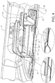
- Figure 3 is a perspective view and Figure 4 is a perspective cross-sectional view.
- the spare wheel cavity 3 comprises a bottom wall 11 and a side wall 13.
- the side wall 13 surrounds the bottom wall 11.
- the housing 8 is sized such that the collision-sensitive object 7 fits in it.
- the housing 8 has a substantially square or rectangular shape with rounded-off corners, thereby substantially forming a three-dimensional shape of a rectangular parallelepiped.
- the collision-sensitive object 7 has a substantially rectangular shape, thereby substantially forming a three-dimensional shape of a rectangular parallelepiped.
- the housing 8 may be large enough to fit a lithium-ion battery 7 suitable for a hybrid vehicle.
- the bottom reinforcement plate 15 may e.g. be attached to the bottom wall 11 by welding.
- the bottom reinforcement plate 15 comprises a step shape 17, which creates an interspace 18 between a main surface 19 of the bottom reinforcement plate 15 and the bottom wall 11.
- the interspace 18 may be used to provide space for a spare wheel attachment means, which is partly located below the bottom reinforcement plate 15 and passes through an opening in the bottom reinforcement plate 15, thereby connecting the spare wheel 5 to the bottom reinforcement plate 15.
- the interspace 18 makes the collision-sensitive object 7 be located vertically above the bottom wall 11.
- the bottom reinforcement plate 15 comprises, as an option, a rear portion 20, which protrudes in a direction towards a rear end of the vehicle 1, such that the rear portion 20 extends to, or substantially extends to, a rear edge 21 of the spare wheel cavity 3.
- a rear portion 20 may help to ascertain the attachment of the collision-sensitive object 7 in case of a low-speed collision from behind.
- the spare wheel cavity 3 further comprises a carrier plate 23 configured to carry the collision-sensitive object 7 on an object carrying portion 25 of the carrier plate 23.
- the carrier plate 23 is attached to the bottom reinforcement plate 15 by attachment means, e.g. screws located at a respective corner of the carrier plate 23.
- the attachment means are preferably configured such that the carrier plate 23 is connected to the bottom reinforcement plate 15 at least during an initial phase of a rear collision scenario, as is further described below, and preferably during the whole rear collision scenario.
- the carrier plate 23 comprises a first force receiver 29, adapted to receive a forward-directed force from behind.
- the first force receiver 29 protrudes in a rearward direction from the object carrying portion 25 of the carrier plate 23.
- forward-directed force is used herein to denote a force directed in a forward direction of the vehicle 1 or in a substantially forward direction of the vehicle 1, such that its forward component is larger than any vertical or transverse component. Such a forward-directed force may arise in case of a rear collision involving the vehicle 1.
- the housing 8 encloses and protects the collision-sensitive object 7, illustrated as the lithium-ion battery.
- the housing 8 is attached to the object carrying portion 25 of the carrier plate 23 by attachment means, e.g. screws.
- the attachment means of the housing 8 are configured such that the housing 8 will remain attached to the carrier plate 23 during a rear collision scenario.
- a second force receiver 33 adapted to receive a forward-directed force from behind, protrudes in a rearward direction from the housing 8, i.e. parallel to the first force receiver 29.
- the second force receiver 33 protrudes from an upper portion 35 of the housing 8, preferably from an upper edge 37 of the housing 8 as is illustrated, and is further connected to a rear side wall of the housing 8 by means of support plates 38 extending vertically.
- the second force receiver 33 may help to prevent too much tilting, e.g. above 90 degrees, of the collision-sensitive object 7 during at least an initial phase of a rear collision, as is further described below in conjunction with Figures 5a-d , illustrating the case with no spare wheel present.
- a reinforcement structure 39 is located in the bottom wall 11 in front of the carrier plate 23.
- the reinforcement structure 39 is configured to at least initially stop a straight forward translational displacement of the carrier plate 23 and to initiate an obliquely upward movement of the carrier plate 23 and thereby also an obliquely upward movement of the collision-sensitive object 7 enclosed in the housing 8 in case of a rear collision scenario.
- the reinforcement structure 39 is formed as a shape element in the bottom wall 11, illustrated as two grooves 41 in the bottom wall 11.
- the grooves 41 extend in a longitudinal direction of the spare wheel cavity 3 and hence in a longitudinal direction of the vehicle 1.
- the grooves 41 constitute less than 20% of the surface portion of the bottom wall 11 being located in front of the carrier plate 23.
- the grooves 41 end at corresponding locations as seen in the longitudinal direction of the vehicle 1, here at a front end of the carrier plate 23, such that the rear ends of the grooves 41 together form a bend line of the bottom wall 11.
- a reinforcement structure forming a separate component may be mounted at the bottom wall 11 or in mounted at the side wall 13 but in such a way that it is located at the bottom wall 11.
- the spare wheel cavity 3 is configured such that, in case the spare wheel cavity 3 is subjected to a forward-directed force from behind, the carrier plate 23 is stopped by the reinforcement structure 39 if the forward-directed force is less than a preselectable level However, if the forward-directed force is equal to or greater than the preselectable level, the reinforcement structure 39 initiates an obliquely upward movement of the carrier plate 23, which rises to pass over the reinforcement structure 39, by tilting the carrier plate 23 at its forward end.
- the preselectable level is related to collision forces occurring in a high-speed collision.
- the carrier plate 23 thereafter also passes over a structural component of the vehicle 1, illustrated as a rear cross member 43 extending in a transverse direction of the vehicle 1 in front of the spare wheel cavity 3.
- the rear cross member 43 is a structural component comprised in a subframe or bodywork of the vehicle 1.
- the housing 8 with its enclosed collision-sensitive object 7 moves together with the carrier plate 23 and thereby also passes over the rear cross member 43 of the vehicle 1.
- the bottom wall 11 forms a first shear plane and the carrier plate 23 forms a second shear plane, which is displaceable in a forward direction in relation to the first shear plane.
- Figures 5a-d and Figures 6a-d illustrate two different scenarios for a rear collision involving the vehicle 1, both being high-speed collisions.
- the housing 8 encloses the collision-sensitive object 7, illustrated as the lithium-ion battery.
- the spare wheel 5 is present in the scenario of Figures 6a-d . It would also be possible, however not illustrated, to have a scenario with only the spare wheel 5 present, and no housing 8 or collision-sensitive object 7.
- Figure 5a illustrates a simplified cross-section of Figure 1 taken along a longitudinal centre-line of the spare wheel cavity 3.
- the carrier plate 23 is stopped by the reinforcement structure 39 as long as the forward-directed force is less than a preselectable level.
- the carrier plate 23 rises by being tilted upwards at its forward end. See Figure 5b .
- the carrier plate 23 is displaced forwards in the vehicle 1 above the reinforcement structure 39, see Figure 5c , and above the rear cross member 43, see Figure 5d .
- the tilting of the carrier plate 23 may be within in the range of from 30 to 90 degrees as seen in relation to its original orientation.
- the housing 8 with its enclosed collision-sensitive object 7 moves together with the carrier plate 23 and thereby also passes over the rear cross member 43. Thereby the problem of stack-up is reduced or preferably avoided.
- the bottom wall 11 forms a first shear plane and the carrier plate 23 forms a second shear plane.
- the bottom wall 11 and the bottom reinforcement plate 15, in particular at the step shape 17, are subjected to deformation inter alia against the rear cross member 43, while the housing 8, the collision-sensitive object 7 and the carrier plate 23 relatively unaffected pass over the rear cross member 43.
- the forward-directed load from the rear collision is taken up by load paths via the first force receiver 29 and the second force receiver 33, which help to guide the displacement of the collision-sensitive object 7. Further, the second force receiver 33 prevents the collision-sensitive object 7 from too much tilting, e.g. above 90 degrees, during the rear collision scenario. In addition or as a complement, the second force receiver 33 may be used to protect the housing 8 and thus the collision-sensitive object 7 from being damaged by a lock of the trunk door.
- Figures 6a-d illustrate the corresponding scenario in case the spare wheel 5 is present.
- Figure 6a illustrates a simplified cross-section of Figure 2 taken along a longitudinal centre-line of the spare wheel cavity 3.
- the wheel rim 9 has a shape configured to fit the housing 8 inside. Thereby the spare wheel 5 will help to protect the collision-sensitive object 7 in case of a rear collision.
- the forward-directed load from the rear collision is initially taken by the spare wheel 5, which transfers it to the carrier plate 23 via the first force receiver 29. Similar as for the scenario of Figures 5a-d , the carrier plate 23 is stopped by the reinforcement structure 39 as long as the forward-directed force is less than the preselectable level. When the forward-directed force reaches the preselectable level, the carrier plate 23 rises by being tilted upwards at its forward end together with the spare wheel 5. See Figure 6b . Thereafter the carrier plate 23 and the spare wheel 5 are displaced forwards in the vehicle 1 above the reinforcement structure 39, see Figure 6c , and above the rear cross member 43, see Figure 6d .
- the housing 8 with its enclosed collision-sensitive object 7 moves together with the carrier plate 23 and the spare wheel 5, and thereby also passes over the rear cross member 43. Consequently, the problem of stack-up is reduced or preferably avoided.
- the bottom wall 11 forms a first shear plane and the carrier plate 23 forms a second shear plane.
- the bottom wall 11 and the bottom reinforcement plate 15, in particular at the step shape 17, are subjected to deformation inter alia against the rear cross member 43, while the housing 8, the collision-sensitive object 7, the spare wheel 5 and the carrier plate 23 relatively unaffected pass over the rear cross member 43.
- the spare wheel cavity as disclosed herein is highly versatile and would work with or without the collision-sensitive object, as well as, with or without the spare wheel.
- the same kind of configuration of the spare wheel cavity may be used for vehicles being equipped in different ways.
- the illustrated embodiments disclose a lithium-ion battery. This kind of battery may be more sensitive to mechanical damage than a conventional lead acid battery and would thus highly benefit from the spare wheel cavity as described herein, in case the vehicle would be subjected to a rear collision.
Landscapes
- Engineering & Computer Science (AREA)
- Chemical & Material Sciences (AREA)
- Combustion & Propulsion (AREA)
- Transportation (AREA)
- Mechanical Engineering (AREA)
- Body Structure For Vehicles (AREA)
- Arrangement Or Mounting Of Propulsion Units For Vehicles (AREA)
Claims (15)
- Reserveradmulde (3) für ein Fahrzeug (1), wobei die Reserveradmulde (3) dazu ausgelegt ist, einen kollisionsempfindlichen Gegenstand (7) zu lagern, wobei die Reserveradmulde (3) eine Bodenwand (11) und eine Seitenwand (13) umfasst,
dadurch gekennzeichnet, dass
die Reserveradmulde (3) ferner Folgendes umfasst:- eine Trägerplatte (23), die direkt oder indirekt an der Bodenwand (11) angebracht ist, wobei die Trägerplatte (23) dazu ausgelegt ist, den kollisionsempfindlichen Gegenstand (7) auf einem den Gegenstand tragenden Abschnitt (25) der Trägerplatte (23) zu tragen, und- eine Verstärkungsstruktur (39), die in oder an der Bodenwand (11) vor der Trägerplatte (23) festgelegt ist. - Reserveradmulde (3) nach Anspruch 1, wobei die Bodenwand (11) dazu ausgelegt ist, eine erste Scherebene zu bilden, und die Trägerplatte (23) dazu ausgelegt ist, eine zweite Scherebene zu bilden, die in einer Vorwärtsrichtung in Bezug auf die erste Scherebene verlagerbar ist, falls die Reserveradmulde (3) einer von hinten nach vorne gerichteten Kraft ausgesetzt ist.
- Reserveradmulde (3) nach einem der vorhergehenden Ansprüche, wobei die Reserveradmulde (3), falls die Reserveradmulde (3) einer von hinten nach vorne gerichteten Kraft ausgesetzt ist, auf eine solche Weise ausgelegt ist, dass- die Verstärkungsstruktur (39) geeignet ist, die Trägerplatte (23) zu stoppen, wenn die nach vorne gerichtete Kraft geringer als ein vorwählbarer Wert ist, und- die Verstärkungsstruktur (39) geeignet ist, die Trägerplatte (23) zu neigen und die Trägerplatte (23) über die Verstärkungsstruktur (39) zu führen, wenn die nach vorne gerichtete Kraft größer oder gleich dem vorwählbaren Wert ist.
- Reserveradmulde (3) nach einem der vorhergehenden Ansprüche, wobei die Verstärkungsstruktur (39) als ein oder mehrere Formelemente in der Bodenwand (11) ausgebildet ist, z.B. eine Rille (41), ein Vorsprung oder eine Stufe.
- Reserveradmulde (3) nach Anspruch 4, wobei das eine oder die mehreren Formelemente (41) weniger als 30% der Fläche der Bodenwand vor der Trägerplatte, vorzugsweise weniger als 20%, ausmacht bzw. ausmachen.
- Reserveradmulde (3) nach Anspruch 4 oder 5, wobei das Formelement (41) seine Haupterstreckung in einer Längsrichtung der Reserveradmulde (3) aufweist.
- Reserveradmulde (3) nach einem der vorhergehenden Ansprüche, wobei die Reserveradmulde (3) ferner eine Bodenverstärkungsplatte (15) umfasst, die dazu ausgelegt ist, die Bodenwand (11) zu verstärken.
- Reserveradmulde (3) nach Anspruch 7, wobei die Bodenverstärkungsplatte (15) eine Hauptfläche (19) umfasst, die vertikal über der Verstärkungsstruktur (39) in oder an der Bodenwand (11), vorzugsweise mit einem Zwischenraum (18) zwischen der Hauptfläche (19) der Bodenverstärkungsplatte (15) und der Bodenwand (11), festgelegt ist.
- Reserveradmulde (3) nach Anspruch 8, wobei die Bodenverstärkungsplatte (15) eine Stufenform (17) umfasst, die einen Zwischenraum (18) zwischen der Hauptfläche (19) der Bodenverstärkungsplatte (15) und der Bodenwand (11) schafft.
- Reserveradmulde (3) nach einem der vorhergehenden Ansprüche, wobei die Trägerplatte (23) eine erste Kraftaufnahme (29) umfasst, die geeignet ist, eine nach vorne gerichtete Kraft aufzunehmen, wobei die erste Kraftaufnahme (29) in einer nach hinten verlaufenden Richtung von dem den Gegenstand tragenden Abschnitt (25) der Trägerplatte (23) vorsteht.
- Reserveradmulde (3) nach einem der vorhergehenden Ansprüche, ferner umfassend ein Gehäuse (8), das dazu ausgelegt ist, den kollisionsempfindlichen Gegenstand (7) wenigstens zum Teil zu umschließen.
- Reserveradmulde (3) nach Anspruch 11, ferner umfassend eine zweite Kraftaufnahme (33), die geeignet ist, eine nach vorne gerichtete Kraft aufzunehmen, wobei die zweite Kraftaufnahme (33) in einer nach hinten verlaufenden Richtung von dem Gehäuse (8) vorsteht, vorzugsweise von einem oberen Abschnitt (35) oder insbesondere von einem oberen Rand (37) des Gehäuses (8) vorsteht.
- Anordnung, umfassend die Reserveradmulde (3) nach einem der vorhergehenden Ansprüche und den kollisionsempfindlichen Gegenstand (7), wobei es sich bei dem kollisionsempfindlichen Gegenstand (7) um eine Batterie, z.B. einen Lithium-Ionen-Akkumulator, handelt.
- Anordnung, umfassend die Reserveradmulde (3) nach einem der Ansprüche 1 bis 12 und ein Reserverad (5), das dazu ausgelegt ist, in der Reserveradmulde (3) gelagert zu werden, wobei das Reserverad (5) eine Radfelge (9) umfasst, die dazu ausgelegt ist, das den kollisionsempfindlichen Gegenstand (7) umschließende Gehäuse (8) zu umgreifen.
- Verfahren zum Verringern des Risikos eines Stauungsproblems im Falle eines Heckaufpralls, in den ein Fahrzeug (1) verwickelt ist, das die Reserveradmulde (3) nach einem der Ansprüche 1 bis 12 und ein Bauteil (43), das vor der Reserveradmulde (3) festgelegt ist, umfasst, wobei das Verfahren Folgendes umfasst:- Neigen der Trägerplatte (23) nach oben an ihrem vorderen Ende und- Verlagern der Trägerplatte (23) nach vorne in dem Fahrzeug (1) über dem Bauteil (43).
Priority Applications (3)
| Application Number | Priority Date | Filing Date | Title |
|---|---|---|---|
| EP16185078.9A EP3287345B1 (de) | 2016-08-22 | 2016-08-22 | Ersatzradhohlraum |
| US15/637,278 US10266211B2 (en) | 2016-08-22 | 2017-06-29 | Spare wheel cavity |
| CN201710695891.0A CN107757735B (zh) | 2016-08-22 | 2017-08-15 | 备用车轮腔 |
Applications Claiming Priority (1)
| Application Number | Priority Date | Filing Date | Title |
|---|---|---|---|
| EP16185078.9A EP3287345B1 (de) | 2016-08-22 | 2016-08-22 | Ersatzradhohlraum |
Publications (2)
| Publication Number | Publication Date |
|---|---|
| EP3287345A1 EP3287345A1 (de) | 2018-02-28 |
| EP3287345B1 true EP3287345B1 (de) | 2019-10-16 |
Family
ID=56740955
Family Applications (1)
| Application Number | Title | Priority Date | Filing Date |
|---|---|---|---|
| EP16185078.9A Active EP3287345B1 (de) | 2016-08-22 | 2016-08-22 | Ersatzradhohlraum |
Country Status (3)
| Country | Link |
|---|---|
| US (1) | US10266211B2 (de) |
| EP (1) | EP3287345B1 (de) |
| CN (1) | CN107757735B (de) |
Families Citing this family (10)
| Publication number | Priority date | Publication date | Assignee | Title |
|---|---|---|---|---|
| US10202028B1 (en) * | 2017-08-09 | 2019-02-12 | Ford Global Technologies, Llc | Vehicle Traction Battery Sub-Frame Assembly |
| JP7047564B2 (ja) * | 2018-04-18 | 2022-04-05 | トヨタ自動車株式会社 | 蓄電装置の固定構造 |
| CN108407898B (zh) * | 2018-05-08 | 2023-08-11 | 广州汽车集团股份有限公司 | 一种前地板笼式梁架结构 |
| JP6831812B2 (ja) * | 2018-07-30 | 2021-02-17 | ダイハツ工業株式会社 | 車両後部構造 |
| FR3086260B1 (fr) * | 2018-09-21 | 2021-01-22 | Renault Sas | Vehicule automobile comprenant une barriere de protection d’un reservoir a carburant |
| EP3822395A1 (de) * | 2019-11-13 | 2021-05-19 | Fundación Imdea Materiales | Nanodrahtnetzwerk |
| CN112373281A (zh) * | 2020-11-30 | 2021-02-19 | 重庆长安汽车股份有限公司 | 一种动力电池安装结构及车辆 |
| JP7528966B2 (ja) * | 2022-02-15 | 2024-08-06 | トヨタ自動車株式会社 | 車体構造 |
| JP2023128523A (ja) | 2022-03-03 | 2023-09-14 | 本田技研工業株式会社 | 車体後部構造 |
| CN117985128A (zh) * | 2022-10-27 | 2024-05-07 | 本田技研工业株式会社 | 车体后部结构 |
Family Cites Families (13)
| Publication number | Priority date | Publication date | Assignee | Title |
|---|---|---|---|---|
| DE9320701U1 (de) | 1993-11-12 | 1995-01-19 | Adam Opel AG, 65428 Rüsselsheim | Kraftfahrzeug mit einer Batterie |
| DE19536511C1 (de) * | 1995-09-29 | 1996-11-21 | Bayerische Motoren Werke Ag | Anordnung eines Bauteils in der Felgenmulde eines Reserverads |
| DE19834134C2 (de) * | 1998-07-29 | 2000-07-06 | Daimler Chrysler Ag | Reserveradmulde eines Kraftfahrzeuges |
| DE10002458C2 (de) * | 2000-01-21 | 2001-01-04 | Audi Ag | Vorrichtung zur Fixierung einer Batterie |
| US6854543B2 (en) * | 2002-11-12 | 2005-02-15 | Daimlerchrysler Corporation | Semicircular battery for a vehicle |
| JP4346928B2 (ja) * | 2003-03-04 | 2009-10-21 | 富士重工業株式会社 | バッテリの取付構造 |
| JP2006256464A (ja) | 2005-03-16 | 2006-09-28 | Toyota Motor Corp | 後部車体構造 |
| DE102006050750A1 (de) * | 2006-10-27 | 2008-04-30 | Daimler Ag | Kraftfahrzeug |
| JP5435350B2 (ja) * | 2009-12-24 | 2014-03-05 | スズキ株式会社 | 車体後部の下部構造 |
| JP5581083B2 (ja) * | 2010-03-19 | 2014-08-27 | 本田技研工業株式会社 | 車体後部構造体 |
| US9007021B2 (en) * | 2010-05-26 | 2015-04-14 | Suzuki Motor Corporation | Installation structure for charging equipment in rear vehicle body |
| EP3064388B1 (de) * | 2013-10-28 | 2019-02-20 | Nissan Motor Co., Ltd | Batterieschutzstruktur |
| CN105270152A (zh) * | 2015-10-30 | 2016-01-27 | 重庆长安汽车股份有限公司 | 混动汽车电池安装结构 |
-
2016
- 2016-08-22 EP EP16185078.9A patent/EP3287345B1/de active Active
-
2017
- 2017-06-29 US US15/637,278 patent/US10266211B2/en active Active
- 2017-08-15 CN CN201710695891.0A patent/CN107757735B/zh active Active
Non-Patent Citations (1)
| Title |
|---|
| None * |
Also Published As
| Publication number | Publication date |
|---|---|
| US10266211B2 (en) | 2019-04-23 |
| CN107757735B (zh) | 2021-03-09 |
| US20180050734A1 (en) | 2018-02-22 |
| EP3287345A1 (de) | 2018-02-28 |
| CN107757735A (zh) | 2018-03-06 |
Similar Documents
| Publication | Publication Date | Title |
|---|---|---|
| US10266211B2 (en) | Spare wheel cavity | |
| CN110239627B (zh) | 车辆后部构造 | |
| EP1902928B1 (de) | Vorderbau eines Kraftfahrzeugs | |
| EP3461692B1 (de) | Sensorschutz und fahrzeug damit | |
| US8881853B2 (en) | Battery pack mounting structure for electric car | |
| EP3064388B1 (de) | Batterieschutzstruktur | |
| CN110239624A (zh) | 车辆下部构造 | |
| US20170088178A1 (en) | Impact load reduction structure | |
| US20230406414A1 (en) | Front vehicle module, and vehicle comprising a front vehicle module | |
| JP6018247B2 (ja) | 自動車後部 | |
| CN106143094A (zh) | 混合动力车辆的行李舱安装结构 | |
| KR102384154B1 (ko) | 차량 | |
| US20150166123A1 (en) | Front vehicle body reinforcing structure | |
| JP5499991B2 (ja) | 車両のボディ構造 | |
| JP6874362B2 (ja) | バッテリパックの保護構造 | |
| JP6156356B2 (ja) | 車両後部構造 | |
| US20220344757A1 (en) | Vehicle battery case | |
| CN120096690A (zh) | 车身前部结构 | |
| CN103386942B (zh) | 车辆中的保险杠装置 | |
| JP2017177931A (ja) | 車両の配線類保護構造 | |
| JP2014180933A (ja) | 車体フロア及び車体フロアに搭載されたバッテリユニットの保護方法 | |
| WO2020170578A1 (ja) | 車載部品支持構造 | |
| US9352784B2 (en) | Adapter for crush rail and torque box | |
| WO2020137102A1 (ja) | 車両の前部構造 | |
| JP5092728B2 (ja) | 車体前部構造 |
Legal Events
| Date | Code | Title | Description |
|---|---|---|---|
| PUAI | Public reference made under article 153(3) epc to a published international application that has entered the european phase |
Free format text: ORIGINAL CODE: 0009012 |
|
| STAA | Information on the status of an ep patent application or granted ep patent |
Free format text: STATUS: THE APPLICATION HAS BEEN PUBLISHED |
|
| AK | Designated contracting states |
Kind code of ref document: A1 Designated state(s): AL AT BE BG CH CY CZ DE DK EE ES FI FR GB GR HR HU IE IS IT LI LT LU LV MC MK MT NL NO PL PT RO RS SE SI SK SM TR |
|
| AX | Request for extension of the european patent |
Extension state: BA ME |
|
| STAA | Information on the status of an ep patent application or granted ep patent |
Free format text: STATUS: REQUEST FOR EXAMINATION WAS MADE |
|
| 17P | Request for examination filed |
Effective date: 20180828 |
|
| RBV | Designated contracting states (corrected) |
Designated state(s): AL AT BE BG CH CY CZ DE DK EE ES FI FR GB GR HR HU IE IS IT LI LT LU LV MC MK MT NL NO PL PT RO RS SE SI SK SM TR |
|
| GRAP | Despatch of communication of intention to grant a patent |
Free format text: ORIGINAL CODE: EPIDOSNIGR1 |
|
| STAA | Information on the status of an ep patent application or granted ep patent |
Free format text: STATUS: GRANT OF PATENT IS INTENDED |
|
| INTG | Intention to grant announced |
Effective date: 20190527 |
|
| GRAS | Grant fee paid |
Free format text: ORIGINAL CODE: EPIDOSNIGR3 |
|
| GRAA | (expected) grant |
Free format text: ORIGINAL CODE: 0009210 |
|
| STAA | Information on the status of an ep patent application or granted ep patent |
Free format text: STATUS: THE PATENT HAS BEEN GRANTED |
|
| AK | Designated contracting states |
Kind code of ref document: B1 Designated state(s): AL AT BE BG CH CY CZ DE DK EE ES FI FR GB GR HR HU IE IS IT LI LT LU LV MC MK MT NL NO PL PT RO RS SE SI SK SM TR |
|
| REG | Reference to a national code |
Ref country code: GB Ref legal event code: FG4D |
|
| REG | Reference to a national code |
Ref country code: CH Ref legal event code: EP |
|
| REG | Reference to a national code |
Ref country code: DE Ref legal event code: R096 Ref document number: 602016022472 Country of ref document: DE |
|
| REG | Reference to a national code |
Ref country code: IE Ref legal event code: FG4D |
|
| REG | Reference to a national code |
Ref country code: AT Ref legal event code: REF Ref document number: 1190994 Country of ref document: AT Kind code of ref document: T Effective date: 20191115 |
|
| REG | Reference to a national code |
Ref country code: NL Ref legal event code: MP Effective date: 20191016 |
|
| REG | Reference to a national code |
Ref country code: LT Ref legal event code: MG4D |
|
| REG | Reference to a national code |
Ref country code: AT Ref legal event code: MK05 Ref document number: 1190994 Country of ref document: AT Kind code of ref document: T Effective date: 20191016 |
|
| PG25 | Lapsed in a contracting state [announced via postgrant information from national office to epo] |
Ref country code: NL Free format text: LAPSE BECAUSE OF FAILURE TO SUBMIT A TRANSLATION OF THE DESCRIPTION OR TO PAY THE FEE WITHIN THE PRESCRIBED TIME-LIMIT Effective date: 20191016 Ref country code: LT Free format text: LAPSE BECAUSE OF FAILURE TO SUBMIT A TRANSLATION OF THE DESCRIPTION OR TO PAY THE FEE WITHIN THE PRESCRIBED TIME-LIMIT Effective date: 20191016 Ref country code: PL Free format text: LAPSE BECAUSE OF FAILURE TO SUBMIT A TRANSLATION OF THE DESCRIPTION OR TO PAY THE FEE WITHIN THE PRESCRIBED TIME-LIMIT Effective date: 20191016 Ref country code: AT Free format text: LAPSE BECAUSE OF FAILURE TO SUBMIT A TRANSLATION OF THE DESCRIPTION OR TO PAY THE FEE WITHIN THE PRESCRIBED TIME-LIMIT Effective date: 20191016 Ref country code: GR Free format text: LAPSE BECAUSE OF FAILURE TO SUBMIT A TRANSLATION OF THE DESCRIPTION OR TO PAY THE FEE WITHIN THE PRESCRIBED TIME-LIMIT Effective date: 20200117 Ref country code: PT Free format text: LAPSE BECAUSE OF FAILURE TO SUBMIT A TRANSLATION OF THE DESCRIPTION OR TO PAY THE FEE WITHIN THE PRESCRIBED TIME-LIMIT Effective date: 20200217 Ref country code: FI Free format text: LAPSE BECAUSE OF FAILURE TO SUBMIT A TRANSLATION OF THE DESCRIPTION OR TO PAY THE FEE WITHIN THE PRESCRIBED TIME-LIMIT Effective date: 20191016 Ref country code: BG Free format text: LAPSE BECAUSE OF FAILURE TO SUBMIT A TRANSLATION OF THE DESCRIPTION OR TO PAY THE FEE WITHIN THE PRESCRIBED TIME-LIMIT Effective date: 20200116 Ref country code: NO Free format text: LAPSE BECAUSE OF FAILURE TO SUBMIT A TRANSLATION OF THE DESCRIPTION OR TO PAY THE FEE WITHIN THE PRESCRIBED TIME-LIMIT Effective date: 20200116 Ref country code: LV Free format text: LAPSE BECAUSE OF FAILURE TO SUBMIT A TRANSLATION OF THE DESCRIPTION OR TO PAY THE FEE WITHIN THE PRESCRIBED TIME-LIMIT Effective date: 20191016 Ref country code: SE Free format text: LAPSE BECAUSE OF FAILURE TO SUBMIT A TRANSLATION OF THE DESCRIPTION OR TO PAY THE FEE WITHIN THE PRESCRIBED TIME-LIMIT Effective date: 20191016 |
|
| PG25 | Lapsed in a contracting state [announced via postgrant information from national office to epo] |
Ref country code: HR Free format text: LAPSE BECAUSE OF FAILURE TO SUBMIT A TRANSLATION OF THE DESCRIPTION OR TO PAY THE FEE WITHIN THE PRESCRIBED TIME-LIMIT Effective date: 20191016 Ref country code: IS Free format text: LAPSE BECAUSE OF FAILURE TO SUBMIT A TRANSLATION OF THE DESCRIPTION OR TO PAY THE FEE WITHIN THE PRESCRIBED TIME-LIMIT Effective date: 20200224 Ref country code: RS Free format text: LAPSE BECAUSE OF FAILURE TO SUBMIT A TRANSLATION OF THE DESCRIPTION OR TO PAY THE FEE WITHIN THE PRESCRIBED TIME-LIMIT Effective date: 20191016 |
|
| PG25 | Lapsed in a contracting state [announced via postgrant information from national office to epo] |
Ref country code: AL Free format text: LAPSE BECAUSE OF FAILURE TO SUBMIT A TRANSLATION OF THE DESCRIPTION OR TO PAY THE FEE WITHIN THE PRESCRIBED TIME-LIMIT Effective date: 20191016 |
|
| REG | Reference to a national code |
Ref country code: DE Ref legal event code: R097 Ref document number: 602016022472 Country of ref document: DE |
|
| PG2D | Information on lapse in contracting state deleted |
Ref country code: IS |
|
| PG25 | Lapsed in a contracting state [announced via postgrant information from national office to epo] |
Ref country code: CZ Free format text: LAPSE BECAUSE OF FAILURE TO SUBMIT A TRANSLATION OF THE DESCRIPTION OR TO PAY THE FEE WITHIN THE PRESCRIBED TIME-LIMIT Effective date: 20191016 Ref country code: ES Free format text: LAPSE BECAUSE OF FAILURE TO SUBMIT A TRANSLATION OF THE DESCRIPTION OR TO PAY THE FEE WITHIN THE PRESCRIBED TIME-LIMIT Effective date: 20191016 Ref country code: DK Free format text: LAPSE BECAUSE OF FAILURE TO SUBMIT A TRANSLATION OF THE DESCRIPTION OR TO PAY THE FEE WITHIN THE PRESCRIBED TIME-LIMIT Effective date: 20191016 Ref country code: RO Free format text: LAPSE BECAUSE OF FAILURE TO SUBMIT A TRANSLATION OF THE DESCRIPTION OR TO PAY THE FEE WITHIN THE PRESCRIBED TIME-LIMIT Effective date: 20191016 Ref country code: EE Free format text: LAPSE BECAUSE OF FAILURE TO SUBMIT A TRANSLATION OF THE DESCRIPTION OR TO PAY THE FEE WITHIN THE PRESCRIBED TIME-LIMIT Effective date: 20191016 Ref country code: IS Free format text: LAPSE BECAUSE OF FAILURE TO SUBMIT A TRANSLATION OF THE DESCRIPTION OR TO PAY THE FEE WITHIN THE PRESCRIBED TIME-LIMIT Effective date: 20200216 |
|
| PLBE | No opposition filed within time limit |
Free format text: ORIGINAL CODE: 0009261 |
|
| STAA | Information on the status of an ep patent application or granted ep patent |
Free format text: STATUS: NO OPPOSITION FILED WITHIN TIME LIMIT |
|
| PG25 | Lapsed in a contracting state [announced via postgrant information from national office to epo] |
Ref country code: SK Free format text: LAPSE BECAUSE OF FAILURE TO SUBMIT A TRANSLATION OF THE DESCRIPTION OR TO PAY THE FEE WITHIN THE PRESCRIBED TIME-LIMIT Effective date: 20191016 Ref country code: SM Free format text: LAPSE BECAUSE OF FAILURE TO SUBMIT A TRANSLATION OF THE DESCRIPTION OR TO PAY THE FEE WITHIN THE PRESCRIBED TIME-LIMIT Effective date: 20191016 |
|
| 26N | No opposition filed |
Effective date: 20200717 |
|
| PG25 | Lapsed in a contracting state [announced via postgrant information from national office to epo] |
Ref country code: SI Free format text: LAPSE BECAUSE OF FAILURE TO SUBMIT A TRANSLATION OF THE DESCRIPTION OR TO PAY THE FEE WITHIN THE PRESCRIBED TIME-LIMIT Effective date: 20191016 |
|
| PG25 | Lapsed in a contracting state [announced via postgrant information from national office to epo] |
Ref country code: MC Free format text: LAPSE BECAUSE OF FAILURE TO SUBMIT A TRANSLATION OF THE DESCRIPTION OR TO PAY THE FEE WITHIN THE PRESCRIBED TIME-LIMIT Effective date: 20191016 |
|
| REG | Reference to a national code |
Ref country code: CH Ref legal event code: PL |
|
| GBPC | Gb: european patent ceased through non-payment of renewal fee |
Effective date: 20200822 |
|
| PG25 | Lapsed in a contracting state [announced via postgrant information from national office to epo] |
Ref country code: LI Free format text: LAPSE BECAUSE OF NON-PAYMENT OF DUE FEES Effective date: 20200831 Ref country code: LU Free format text: LAPSE BECAUSE OF NON-PAYMENT OF DUE FEES Effective date: 20200822 Ref country code: CH Free format text: LAPSE BECAUSE OF NON-PAYMENT OF DUE FEES Effective date: 20200831 |
|
| REG | Reference to a national code |
Ref country code: BE Ref legal event code: MM Effective date: 20200831 |
|
| PG25 | Lapsed in a contracting state [announced via postgrant information from national office to epo] |
Ref country code: GB Free format text: LAPSE BECAUSE OF NON-PAYMENT OF DUE FEES Effective date: 20200822 Ref country code: IE Free format text: LAPSE BECAUSE OF NON-PAYMENT OF DUE FEES Effective date: 20200822 Ref country code: BE Free format text: LAPSE BECAUSE OF NON-PAYMENT OF DUE FEES Effective date: 20200831 |
|
| PG25 | Lapsed in a contracting state [announced via postgrant information from national office to epo] |
Ref country code: TR Free format text: LAPSE BECAUSE OF FAILURE TO SUBMIT A TRANSLATION OF THE DESCRIPTION OR TO PAY THE FEE WITHIN THE PRESCRIBED TIME-LIMIT Effective date: 20191016 Ref country code: MT Free format text: LAPSE BECAUSE OF FAILURE TO SUBMIT A TRANSLATION OF THE DESCRIPTION OR TO PAY THE FEE WITHIN THE PRESCRIBED TIME-LIMIT Effective date: 20191016 Ref country code: CY Free format text: LAPSE BECAUSE OF FAILURE TO SUBMIT A TRANSLATION OF THE DESCRIPTION OR TO PAY THE FEE WITHIN THE PRESCRIBED TIME-LIMIT Effective date: 20191016 |
|
| PG25 | Lapsed in a contracting state [announced via postgrant information from national office to epo] |
Ref country code: MK Free format text: LAPSE BECAUSE OF FAILURE TO SUBMIT A TRANSLATION OF THE DESCRIPTION OR TO PAY THE FEE WITHIN THE PRESCRIBED TIME-LIMIT Effective date: 20191016 |
|
| P01 | Opt-out of the competence of the unified patent court (upc) registered |
Effective date: 20231212 |
|
| PGFP | Annual fee paid to national office [announced via postgrant information from national office to epo] |
Ref country code: IT Payment date: 20240723 Year of fee payment: 9 |
|
| PGFP | Annual fee paid to national office [announced via postgrant information from national office to epo] |
Ref country code: DE Payment date: 20250724 Year of fee payment: 10 |
|
| PGFP | Annual fee paid to national office [announced via postgrant information from national office to epo] |
Ref country code: FR Payment date: 20250723 Year of fee payment: 10 |