EP3287356A1 - Hélice en composite ultra-légère pour moteur hors-bord - Google Patents
Hélice en composite ultra-légère pour moteur hors-bord Download PDFInfo
- Publication number
- EP3287356A1 EP3287356A1 EP17784153.3A EP17784153A EP3287356A1 EP 3287356 A1 EP3287356 A1 EP 3287356A1 EP 17784153 A EP17784153 A EP 17784153A EP 3287356 A1 EP3287356 A1 EP 3287356A1
- Authority
- EP
- European Patent Office
- Prior art keywords
- hub
- fitting
- blade
- propeller
- core
- Prior art date
- Legal status (The legal status is an assumption and is not a legal conclusion. Google has not performed a legal analysis and makes no representation as to the accuracy of the status listed.)
- Withdrawn
Links
- 239000002131 composite material Substances 0.000 title claims abstract description 16
- 238000005452 bending Methods 0.000 claims description 13
- 230000008878 coupling Effects 0.000 claims description 5
- 238000010168 coupling process Methods 0.000 claims description 5
- 238000005859 coupling reaction Methods 0.000 claims description 5
- 230000007423 decrease Effects 0.000 claims description 4
- 229910052782 aluminium Inorganic materials 0.000 claims description 2
- XAGFODPZIPBFFR-UHFFFAOYSA-N aluminium Chemical compound [Al] XAGFODPZIPBFFR-UHFFFAOYSA-N 0.000 claims description 2
- 239000000446 fuel Substances 0.000 abstract description 5
- 238000004519 manufacturing process Methods 0.000 description 5
- 230000008439 repair process Effects 0.000 description 4
- XLYOFNOQVPJJNP-UHFFFAOYSA-N water Substances O XLYOFNOQVPJJNP-UHFFFAOYSA-N 0.000 description 3
- 229910052755 nonmetal Inorganic materials 0.000 description 2
- 230000008901 benefit Effects 0.000 description 1
- 238000002485 combustion reaction Methods 0.000 description 1
- 230000002950 deficient Effects 0.000 description 1
- 230000000694 effects Effects 0.000 description 1
- 238000005516 engineering process Methods 0.000 description 1
- 238000007667 floating Methods 0.000 description 1
- 238000001746 injection moulding Methods 0.000 description 1
- 238000012423 maintenance Methods 0.000 description 1
- 238000000034 method Methods 0.000 description 1
- 150000002843 nonmetals Chemical class 0.000 description 1
- 230000008569 process Effects 0.000 description 1
- 230000000717 retained effect Effects 0.000 description 1
- 230000035939 shock Effects 0.000 description 1
- 238000003466 welding Methods 0.000 description 1
Images


Classifications
-
- B—PERFORMING OPERATIONS; TRANSPORTING
- B63—SHIPS OR OTHER WATERBORNE VESSELS; RELATED EQUIPMENT
- B63H—MARINE PROPULSION OR STEERING
- B63H1/00—Propulsive elements directly acting on water
- B63H1/02—Propulsive elements directly acting on water of rotary type
- B63H1/12—Propulsive elements directly acting on water of rotary type with rotation axis substantially in propulsive direction
- B63H1/14—Propellers
- B63H1/26—Blades
-
- B—PERFORMING OPERATIONS; TRANSPORTING
- B63—SHIPS OR OTHER WATERBORNE VESSELS; RELATED EQUIPMENT
- B63H—MARINE PROPULSION OR STEERING
- B63H1/00—Propulsive elements directly acting on water
- B63H1/02—Propulsive elements directly acting on water of rotary type
- B63H1/12—Propulsive elements directly acting on water of rotary type with rotation axis substantially in propulsive direction
- B63H1/14—Propellers
- B63H1/20—Hubs; Blade connections
-
- F—MECHANICAL ENGINEERING; LIGHTING; HEATING; WEAPONS; BLASTING
- F01—MACHINES OR ENGINES IN GENERAL; ENGINE PLANTS IN GENERAL; STEAM ENGINES
- F01D—NON-POSITIVE DISPLACEMENT MACHINES OR ENGINES, e.g. STEAM TURBINES
- F01D5/00—Blades; Blade-carrying members; Heating, heat-insulating, cooling or antivibration means on the blades or the members
- F01D5/12—Blades
- F01D5/28—Selecting particular materials; Particular measures relating thereto; Measures against erosion or corrosion
- F01D5/282—Selecting composite materials, e.g. blades with reinforcing filaments
-
- B—PERFORMING OPERATIONS; TRANSPORTING
- B63—SHIPS OR OTHER WATERBORNE VESSELS; RELATED EQUIPMENT
- B63B—SHIPS OR OTHER WATERBORNE VESSELS; EQUIPMENT FOR SHIPPING
- B63B2231/00—Material used for some parts or elements, or for particular purposes
- B63B2231/02—Metallic materials
- B63B2231/10—Aluminium or aluminium alloys
-
- B—PERFORMING OPERATIONS; TRANSPORTING
- B63—SHIPS OR OTHER WATERBORNE VESSELS; RELATED EQUIPMENT
- B63B—SHIPS OR OTHER WATERBORNE VESSELS; EQUIPMENT FOR SHIPPING
- B63B2231/00—Material used for some parts or elements, or for particular purposes
- B63B2231/40—Synthetic materials
-
- B—PERFORMING OPERATIONS; TRANSPORTING
- B63—SHIPS OR OTHER WATERBORNE VESSELS; RELATED EQUIPMENT
- B63H—MARINE PROPULSION OR STEERING
- B63H23/00—Transmitting power from propulsion power plant to propulsive elements
- B63H23/32—Other parts
- B63H23/34—Propeller shafts; Paddle-wheel shafts; Attachment of propellers on shafts
-
- B—PERFORMING OPERATIONS; TRANSPORTING
- B63—SHIPS OR OTHER WATERBORNE VESSELS; RELATED EQUIPMENT
- B63H—MARINE PROPULSION OR STEERING
- B63H5/00—Arrangements on vessels of propulsion elements directly acting on water
- B63H5/07—Arrangements on vessels of propulsion elements directly acting on water of propellers
-
- F—MECHANICAL ENGINEERING; LIGHTING; HEATING; WEAPONS; BLASTING
- F04—POSITIVE - DISPLACEMENT MACHINES FOR LIQUIDS; PUMPS FOR LIQUIDS OR ELASTIC FLUIDS
- F04D—NON-POSITIVE-DISPLACEMENT PUMPS
- F04D29/00—Details, component parts, or accessories
- F04D29/26—Rotors specially for elastic fluids
- F04D29/32—Rotors specially for elastic fluids for axial flow pumps
- F04D29/34—Blade mountings
Definitions
- the present invention relates to a lightweight composite propeller for an outboard motor.
- An outboard motor is a propulsion system that is mounted at the rear of a vessel such as a small boat and vessels can be propelled by the outboard motor.
- Outboard motors are usually mounted at the stern of vessels, but are mounted on small boats other than rubber boats.
- outboard motors are manufactured separately from vessels. That is, an outboard motor uses an internal combustion engine, but is very different in structure and strokes from those of vehicle or motorcycles, so the manufacturer of outboard motors may be different from the manufactures of vessels.
- the propellers for outboard motors are also imported, and expensive non-metals are used for the propellers of outboard motors to maximize anticorrosion and strength, so the propellers are heavy and difficult to manufacture in large quantities through precision casing. Further, if the propellers are damaged, their power is reduced, vibration is generated, and welding is required for repair thereof, so repair is expensive and time-consuming. Further, if the propellers are severely damaged, the entire propeller should be replaced, which is costly.
- the present invention has been made in an effort to solve the problems and an object of the present invention is to provide a lightweight composite propeller for an outboard motor, wherein the propeller has a separate hub and blades that can be easily repaired when damaged, improves fuel efficiency because a lightweight composite material is used therefor, and is easily manufactured in large quantities.
- a lightweight composite propeller for an outboard motor includes: a hub having a cylindrical body and having an axial hole at a center; blade cores disposed on an outer side of the hub; a rubber bushing disposed in the hole of the hub; and a circular ring-shaped cap disposed at a front end of the hub to prevent the blade cores from being pulled out forward from the hub, in which the blade cores are each an assembly of a blade and a core, and the core is formed by integrally coupling in advance a portion of a body which forms the outer side of the hub to a lower end of the blade, and has a structure for combining and separating the hub and the blade core.
- the hub, the blades, and the rubber bushing can be easily replaced, whereby repair cost and time can be reduced. Further, the weight of the product is reduced by using a composite material, so it is possible to improve fuel efficiency and manufacture the product in large quantities.
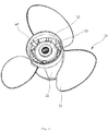
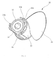
- FIGS. 1 and 2 are an assembly view and an exploded view of the present invention, respectively.
- the hub 10 is coupled to a shaft (not shown) and the blades 21 are combined with the hub 10.
- the hub 10 coupled to the shaft is rotated.
- the blades 21 combined with the hub 10 are rotated, thereby generating thrust.
- the hub 10 and the blades 21 are integrally formed in common propellers, so it is difficult to separate later the blades 21 from the hub 10.
- the blades 21 and the hub 10 are seperably formed in the present invention.
- the assembly of a blade 21 and the hub 10 can be seen from FIG. 3
- the hub 10 and blade 21 separated from each other can be seen from FIGS. 4 and 5 , respectively.
- the separable structure of the blades 21 and the hub 10 is described in detail hereafter.
- a specific separable structure called a 'blade core' 20 ( FIG. 5 ) is employed to separate and combine the hub 10 and the blades 21 in the present invention.
- the blade core 20 is an assembly of a blade 21 and a core 22.
- the core 22 is formed by integrally coupling in advance a portion of a body which forms the outer side of the hub 10 to the lower end of a blade 21, so the blade 21 can be combined with and separated from the hub 10 by the core 22.
- the core 22 of the blade core 20 covers the outer side of the hub 10 in close contact with the outer side, so this assembly substantially functions as the hub 10 in terms of the external shape ( FIGS. 1 and 3 ).
- the core 22 has fitting grooves 22a to be coupled to the hub 10 ( FIGS. 3 and 5 ).
- the fitting grooves 22a have a U-shaped cross-section and are formed axially straight.
- the hub 10 has fitting projections 10a formed with regular intervals around the outer side of the cylindrical body ( FIGS. 3 and 4 ) .
- the fitting projections 10a have a T-shaped cross-section and are formed axially straight.
- the blade core 20 is combined with the hub 10 by pushing backward the blade core 20 with the fitting projections 10a partially fitted in the rear ends of the fitting grooves 22a ( FIG. 2 ).
- the blade core 20 is pulled forward in this state, the blade core 20 is pulled off and separated from the hub 10 (FIG. 20).
- the fitting grooves 22a and the fitting projections 10a are both formed axially straight, it is possible to simply fit and pull the blade core 20 onto and out of the hub 10 only by straightly pushing or pulling the blade core 20.
- the width of the fitting grooves 22a gradually decreases as it goes to the center of the shaft ( FIGS. 3 and 5 ), and the width of the fitting projections 10a gradually decreases as it goes to the center of the shaft ( FIGS. 3 and 4 ). Accordingly, one the blade core 20 is fitted on the hub 10, the blade core 20 cannot be circumferentially separated ( FIG. 3 ). Therefore, even if a large force (centrifugal force) is circumferentially applied to the blade core 20 when the propeller is rotated, the blade core 20 can remain combined with the hub 10 against the force.
- a bending portion 22a-1 is formed at a first side of each of the fitting grooves 22a by bending both ends of the core 22 toward the center of the shaft and a fitting portion 22a-2 extending toward the center of the shaft is formed at a second side of each of the fitting grooves 22a to face the bending portion 22a-1 with the fitting grooves 22a therebetween ( FIG. 5 ).
- the fitting projections 10a each have flanges 10a-1 at both sides on the top and a recession 10a-2 formed between the flanges 10a-1 at both sides ( FIG. 4 ).
- fitting groove 22a and the fitting projection 10a When the fitting groove 22a and the fitting projection 10a are fitted, the bending portion 22a-1 is fitted in the left or right half of the recession 10a-2 and the fitting portion 22a-2 is fitted on any one of the flanges 10a-1 to cover the flange 10a-1 ( FIG. 3 ). Accordingly, fitting groove 22a is supported at two positions of the left and right sides on the flange 10a-1, which has the following important technical meaning. Referring to FIG. 1 , three blade cores 20 are fitted on the hub 10 to form one complete propeller. The propeller is repeatedly rotated clockwise (forward movement) and counterclockwise (backward movement) while a vessel is sailing, so clockwise or counterclockwise force is also repeatedly applied to the blade cores 20.
- the fitting grooves 22a at both ends of the cores 22 of three blade cores 20 are fitted on the fitting projections 10a to assembly a propeller, in which two bending portions 22a-1 are fitted in contact with each other in the left and right halves of the recession 10a-2 of each of the fitting projections 10a.
- the flanges 10a-1 hold the blade cores 20 such that the blade cores 20 are not biased to one side when the propeller is rotated clockwise or counterclockwise.
- the fitting groove 22a is covered with the bending portion 22a-1, the fitting portion 22a-2, and the core 22 at the first side, the second side, and the top, respectively, the fitting projections 10a are hidden not to be exposed to the outer side by the cores 22 when the propeller is assembled. Therefore, according to the present invention, it is possible to prevent damage to the fitting projections 10a, that is, the hub 10 in a broad sense. That is, the propeller frequently hits against objects under water while a vessel is sailed, so if an object directly hits against a fitting projection 10a and the fitting projection 10a is damaged or broken, the entire hub 10 should be replaced. Obviously, repairing is difficult and costs a lot of money in this case.
- the fitting projections 10a are not exposed to the outside and the parts that may hit against floating object in water are limited not to the fitting projections 10a or the hub 10, but only to the blade cores 20. Accordingly, if a blade core 20 is damaged or broken by hitting against an object under water, it is possible to simply repair the propeller by replacing only the blade core 20. As described above, the present invention has a considerable advantage even in terms of maintenance.
- a stopper step 11 is formed at the rear end of the hub 10 ( FIGS. 3 and 4 ).
- the stopping flange 11 protrudes around the hub 10 and prevents the blade cores 20 fitted on the hub 10 from being pulled out backward from the hub 10 ( FIG. 2 ).
- a circular ring-shaped cap 40 is fitted on the front end of the hub 10 after the blade cores 20 are fitted on the hub 10 ( FIGS. 1 and 2 ). Accordingly, the blade cores 20 are prevented from being pulled out forward from the hub 10.
- the cap 40 may be fixed to the hub 10 by bolts. According to the present invention, as described above, it is possible to very firmly combine the blade cores 20 and the hub 10 and increase the durability of the product through the coupling structure of the fitting grooves 22a and the fitting projections 10a, the stopping flange 11, and the cap 40. In order to disassemble the propeller of the present invention, a worker has only to separate the cap 40 first.
- the hub 10 is made of aluminum and, the blade cores 20 and the cap 40 are made of a composite material in the present invention, thereby securing anticorrosion and strength of the product and reducing the weight.
- the blade cores 20 and the cap 40 are manufactured by injection-molding a composite material so that the product can be manufactured in large quantities and the manufacturing cost can be reduced.
- An axial hole 12 is formed through the center of the hub 10 and a rubber bushing 30 is disposed in the hole 12 ( FIGS. 2 and 4 ).
- the rubber bushing 30 is fitted on the shaft inside the hub 10 to attenuate a shock that is applied to the shaft, but the rubber bushing 30 may burst when excessive external force is applied. In this case, the rubber bushing 30 should be replaced with new one.
- the rubber bushing 30 is too tightly fitted in the hub 10 not to be easily pulled out, if the rubber bushing 30 bursts while the vessel is in use, it is impossible to manually replace the rubber bushing 30, which causes a difficult situation.
- the rubber bushing 30 in the present invention is designed to have an appropriate size so that it can be easily replaced by a person, that is, the diameter of the rubber bushing 30 may be designed to be 5 to 10mm smaller than the diameter of the hole 12.
- the rubber bushing 30 is made of rubber, it is sufficiently possible for a person to reduce the diameter of the rubber bushing 30 by 5 to 10mm when pushing the rubber bushing 30 into the hole 12.
- the rubber bushing 30 inserted in the hole 12 is close contact with the hole 12 due to the elasticity of rubber, so it is tightly fitted in the hub 10.
- the hub 10 when the propeller for an outboard motor is damaged, the hub 10, the blades 21, and the rubber bushing 30 can be easily replaced, so repairing requires less cost and time. Further, the weight of the product is reduced by using a composite material, so it is possible to improve fuel efficiency and manufacture the product in large quantities.
- the present invention repairing takes less cost and time when the propeller for an outboard is damaged, fuel efficiency can be improved by using a composite material, and the propeller can be manufactured in large quantities. Therefore, the present invention can achieve practical and economic values through wide use in shipbuilding and marine engineering fields.
Landscapes
- Engineering & Computer Science (AREA)
- Chemical & Material Sciences (AREA)
- Mechanical Engineering (AREA)
- Combustion & Propulsion (AREA)
- Ocean & Marine Engineering (AREA)
- Materials Engineering (AREA)
- Composite Materials (AREA)
- General Engineering & Computer Science (AREA)
- Structures Of Non-Positive Displacement Pumps (AREA)
Applications Claiming Priority (2)
| Application Number | Priority Date | Filing Date | Title |
|---|---|---|---|
| KR2020160002722U KR200484377Y1 (ko) | 2016-05-18 | 2016-05-18 | 선외기용 초경량 복합재료 프로펠러 |
| PCT/KR2017/005045 WO2017200256A1 (fr) | 2016-05-18 | 2017-05-16 | Hélice en composite ultra-légère pour moteur hors-bord |
Publications (2)
| Publication Number | Publication Date |
|---|---|
| EP3287356A1 true EP3287356A1 (fr) | 2018-02-28 |
| EP3287356A4 EP3287356A4 (fr) | 2018-12-12 |
Family
ID=60326361
Family Applications (1)
| Application Number | Title | Priority Date | Filing Date |
|---|---|---|---|
| EP17784153.3A Withdrawn EP3287356A4 (fr) | 2016-05-18 | 2017-05-16 | Hélice en composite ultra-légère pour moteur hors-bord |
Country Status (6)
| Country | Link |
|---|---|
| US (1) | US10926851B2 (fr) |
| EP (1) | EP3287356A4 (fr) |
| JP (1) | JP3221317U (fr) |
| KR (1) | KR200484377Y1 (fr) |
| CN (1) | CN208741940U (fr) |
| WO (1) | WO2017200256A1 (fr) |
Cited By (2)
| Publication number | Priority date | Publication date | Assignee | Title |
|---|---|---|---|---|
| WO2020225049A1 (fr) * | 2019-05-03 | 2020-11-12 | Invent Umwelt- Und Verfahrenstechnik Ag | Hélice et agitateur pour la circulation des eaux usées dans un clarificateur |
| WO2022129676A1 (fr) * | 2020-12-18 | 2022-06-23 | Aker Arctic Technology Oy | Hélice marine |
Families Citing this family (6)
| Publication number | Priority date | Publication date | Assignee | Title |
|---|---|---|---|---|
| US12030606B2 (en) | 2016-05-27 | 2024-07-09 | Sharrow Engineering Llc | Propeller |
| USD987545S1 (en) * | 2017-05-25 | 2023-05-30 | Sharrow Engineering Llc | Propeller |
| US10875615B1 (en) * | 2018-08-20 | 2020-12-29 | Brunswick Corporation | Systems and methods for reducing porosity in propellers |
| USD894055S1 (en) * | 2018-09-11 | 2020-08-25 | Brunswick Corporation | Shock absorbing hub assembly for supporting a propeller on a marine propulsion apparatus |
| JP7375328B2 (ja) * | 2019-04-15 | 2023-11-08 | スズキ株式会社 | 船舶推進装置用プロペラ |
| CN115924042B (zh) * | 2022-11-14 | 2026-01-02 | 本特力船舶科技(苏州)有限公司 | 一种轻便组装式船用舵桨装置 |
Family Cites Families (16)
| Publication number | Priority date | Publication date | Assignee | Title |
|---|---|---|---|---|
| US3246699A (en) * | 1964-06-10 | 1966-04-19 | Outboard Marine Corp | Propeller |
| US4930987A (en) * | 1989-05-24 | 1990-06-05 | Brad Stahl | Marine propeller and hub assembly of plastic |
| US5180286A (en) * | 1990-09-25 | 1993-01-19 | Dean Peter E | Propeller assembly |
| US5354177A (en) * | 1993-11-30 | 1994-10-11 | Chang Song H | Fan |
| US6471481B2 (en) * | 2001-01-02 | 2002-10-29 | Turning Point Propellers, Inc. | Hub assembly for marine propeller |
| US7056092B2 (en) * | 2004-04-09 | 2006-06-06 | Stahl Bradford C | Modular propeller |
| WO2006130899A1 (fr) * | 2005-06-09 | 2006-12-14 | Aimbridge Pty Ltd | Helice pour systeme de propulsion marine |
| US20100189563A1 (en) * | 2009-01-27 | 2010-07-29 | Gonzalez Abal Pablo Alfonso | Propeller for vessels |
| KR100927698B1 (ko) * | 2009-03-10 | 2009-11-18 | 에이원마린테크 주식회사 | 프로펠러보스 결합구조 |
| KR101211358B1 (ko) * | 2010-06-03 | 2012-12-13 | 한국기계연구원 | 유연 프로펠러 및 이의 제조방법 |
| TR201009193A1 (tr) * | 2010-11-05 | 2012-05-21 | Nevres Ülgen Mehmet | Denizcilikte kullanılan bir pervane. |
| KR101312972B1 (ko) | 2012-02-13 | 2013-10-01 | 재단법인 중소조선연구원 | 안벽 고정식 선외기 프로펠러 추력 및 토크 계측장치 |
| TWM441048U (en) * | 2012-06-18 | 2012-11-11 | qing-huang Wang | Fan blade |
| US9550555B2 (en) * | 2013-11-15 | 2017-01-24 | Mehmet Nevres ULGEN | Propeller arrangement for marine vehicles |
| KR20150080852A (ko) * | 2014-01-02 | 2015-07-10 | 대우조선해양 주식회사 | 블레이드의 결합이 용이한 선박용 프로펠러 |
| US9944372B1 (en) * | 2015-09-16 | 2018-04-17 | Bradford C. Stahl | Efficient reverse thrusting modular propeller |
-
2016
- 2016-05-18 KR KR2020160002722U patent/KR200484377Y1/ko active Active
-
2017
- 2017-05-16 US US16/079,981 patent/US10926851B2/en not_active Expired - Fee Related
- 2017-05-16 WO PCT/KR2017/005045 patent/WO2017200256A1/fr not_active Ceased
- 2017-05-16 CN CN201790000227.3U patent/CN208741940U/zh not_active Expired - Fee Related
- 2017-05-16 EP EP17784153.3A patent/EP3287356A4/fr not_active Withdrawn
- 2017-05-16 JP JP2018600113U patent/JP3221317U/ja not_active Expired - Fee Related
Cited By (3)
| Publication number | Priority date | Publication date | Assignee | Title |
|---|---|---|---|---|
| WO2020225049A1 (fr) * | 2019-05-03 | 2020-11-12 | Invent Umwelt- Und Verfahrenstechnik Ag | Hélice et agitateur pour la circulation des eaux usées dans un clarificateur |
| US12017193B2 (en) | 2019-05-03 | 2024-06-25 | Invent Umwelt-Und Verfahrenstechnik Ag | Propeller and stirrer for circulating wastewater in a clarifier |
| WO2022129676A1 (fr) * | 2020-12-18 | 2022-06-23 | Aker Arctic Technology Oy | Hélice marine |
Also Published As
| Publication number | Publication date |
|---|---|
| KR200484377Y1 (ko) | 2017-08-30 |
| JP3221317U (ja) | 2019-05-23 |
| US20190061892A1 (en) | 2019-02-28 |
| WO2017200256A1 (fr) | 2017-11-23 |
| EP3287356A4 (fr) | 2018-12-12 |
| CN208741940U (zh) | 2019-04-16 |
| US10926851B2 (en) | 2021-02-23 |
Similar Documents
| Publication | Publication Date | Title |
|---|---|---|
| US10926851B2 (en) | Lightweight composite propellers for outboard motor | |
| US7056092B2 (en) | Modular propeller | |
| US4930987A (en) | Marine propeller and hub assembly of plastic | |
| US9868498B2 (en) | Modular azimuth thruster | |
| US10494070B2 (en) | Propeller assembly | |
| US9308978B2 (en) | Marine propeller having demountable blades | |
| EP2484583A1 (fr) | Dispositif de propulsion de bateaux | |
| US20150139801A1 (en) | Propeller Arrangement for Marine Vehicles | |
| US9011100B2 (en) | Demountable propeller | |
| JP2009029268A (ja) | 舶用プロペラ | |
| US20120269639A1 (en) | Propeller for outboard motor | |
| WO2018075216A1 (fr) | Appareil et système de retenue arrière de pale d'hélice | |
| JP6112649B2 (ja) | 船舶用プロペラ | |
| KR101291176B1 (ko) | 선박용 러더 | |
| US9499245B2 (en) | Boat propeller nut | |
| KR20150078877A (ko) | 걸쇠형 결합부를 갖는 선박용 프로펠러 | |
| WO2018075214A1 (fr) | Appareil et système de retenue avant de pale d'hélice | |
| KR101533681B1 (ko) | 블레이드의 탈부착이 용이한 선박용 프로펠러 조립체 | |
| EP3088295B1 (fr) | Buse d'unité de propulsion modulaire | |
| KR102120292B1 (ko) | 선박용 프로펠러 | |
| US20160107737A1 (en) | Apparatus for propelling watercraft | |
| KR101955413B1 (ko) | 선박 연료 절감형 다이버젠트 프로펠러 커버캡 | |
| KR101457910B1 (ko) | 후류고정날개를 구비한 선박 | |
| JPH08258791A (ja) | 船舶のステータ付プロペラ装置 | |
| KR101447867B1 (ko) | 후류 고정날개를 구비한 선박 |
Legal Events
| Date | Code | Title | Description |
|---|---|---|---|
| STAA | Information on the status of an ep patent application or granted ep patent |
Free format text: STATUS: UNKNOWN |
|
| STAA | Information on the status of an ep patent application or granted ep patent |
Free format text: STATUS: THE INTERNATIONAL PUBLICATION HAS BEEN MADE |
|
| PUAI | Public reference made under article 153(3) epc to a published international application that has entered the european phase |
Free format text: ORIGINAL CODE: 0009012 |
|
| STAA | Information on the status of an ep patent application or granted ep patent |
Free format text: STATUS: REQUEST FOR EXAMINATION WAS MADE |
|
| 17P | Request for examination filed |
Effective date: 20171025 |
|
| AK | Designated contracting states |
Kind code of ref document: A1 Designated state(s): AL AT BE BG CH CY CZ DE DK EE ES FI FR GB GR HR HU IE IS IT LI LT LU LV MC MK MT NL NO PL PT RO RS SE SI SK SM TR |
|
| AX | Request for extension of the european patent |
Extension state: BA ME |
|
| A4 | Supplementary search report drawn up and despatched |
Effective date: 20181112 |
|
| RIC1 | Information provided on ipc code assigned before grant |
Ipc: B63H 1/20 20060101ALI20181106BHEP Ipc: B63H 5/07 20060101ALI20181106BHEP Ipc: B63H 1/14 20060101AFI20181106BHEP |
|
| GRAP | Despatch of communication of intention to grant a patent |
Free format text: ORIGINAL CODE: EPIDOSNIGR1 |
|
| STAA | Information on the status of an ep patent application or granted ep patent |
Free format text: STATUS: GRANT OF PATENT IS INTENDED |
|
| DAV | Request for validation of the european patent (deleted) | ||
| DAX | Request for extension of the european patent (deleted) | ||
| INTG | Intention to grant announced |
Effective date: 20190625 |
|
| STAA | Information on the status of an ep patent application or granted ep patent |
Free format text: STATUS: THE APPLICATION IS DEEMED TO BE WITHDRAWN |
|
| 18D | Application deemed to be withdrawn |
Effective date: 20191106 |