EP3287609B1 - System und verfahren zur erkennung des bruchs einer turbofan-welle - Google Patents
System und verfahren zur erkennung des bruchs einer turbofan-welle Download PDFInfo
- Publication number
- EP3287609B1 EP3287609B1 EP17184140.6A EP17184140A EP3287609B1 EP 3287609 B1 EP3287609 B1 EP 3287609B1 EP 17184140 A EP17184140 A EP 17184140A EP 3287609 B1 EP3287609 B1 EP 3287609B1
- Authority
- EP
- European Patent Office
- Prior art keywords
- change
- rotational speed
- rate
- filtered
- squared
- Prior art date
- Legal status (The legal status is an assumption and is not a legal conclusion. Google has not performed a legal analysis and makes no representation as to the accuracy of the status listed.)
- Active
Links
Images



Classifications
-
- F—MECHANICAL ENGINEERING; LIGHTING; HEATING; WEAPONS; BLASTING
- F01—MACHINES OR ENGINES IN GENERAL; ENGINE PLANTS IN GENERAL; STEAM ENGINES
- F01D—NON-POSITIVE DISPLACEMENT MACHINES OR ENGINES, e.g. STEAM TURBINES
- F01D21/00—Shutting-down of machines or engines, e.g. in emergency; Regulating, controlling, or safety means not otherwise provided for
- F01D21/02—Shutting-down responsive to overspeed
-
- F—MECHANICAL ENGINEERING; LIGHTING; HEATING; WEAPONS; BLASTING
- F01—MACHINES OR ENGINES IN GENERAL; ENGINE PLANTS IN GENERAL; STEAM ENGINES
- F01D—NON-POSITIVE DISPLACEMENT MACHINES OR ENGINES, e.g. STEAM TURBINES
- F01D21/00—Shutting-down of machines or engines, e.g. in emergency; Regulating, controlling, or safety means not otherwise provided for
- F01D21/003—Arrangements for testing or measuring
-
- F—MECHANICAL ENGINEERING; LIGHTING; HEATING; WEAPONS; BLASTING
- F01—MACHINES OR ENGINES IN GENERAL; ENGINE PLANTS IN GENERAL; STEAM ENGINES
- F01D—NON-POSITIVE DISPLACEMENT MACHINES OR ENGINES, e.g. STEAM TURBINES
- F01D5/00—Blades; Blade-carrying members; Heating, heat-insulating, cooling or antivibration means on the blades or the members
- F01D5/02—Blade-carrying members, e.g. rotors
-
- F—MECHANICAL ENGINEERING; LIGHTING; HEATING; WEAPONS; BLASTING
- F04—POSITIVE - DISPLACEMENT MACHINES FOR LIQUIDS; PUMPS FOR LIQUIDS OR ELASTIC FLUIDS
- F04D—NON-POSITIVE-DISPLACEMENT PUMPS
- F04D19/00—Axial-flow pumps
- F04D19/002—Axial flow fans
-
- G—PHYSICS
- G01—MEASURING; TESTING
- G01M—TESTING STATIC OR DYNAMIC BALANCE OF MACHINES OR STRUCTURES; TESTING OF STRUCTURES OR APPARATUS, NOT OTHERWISE PROVIDED FOR
- G01M15/00—Testing of engines
- G01M15/14—Testing gas-turbine engines or jet-propulsion engines
-
- F—MECHANICAL ENGINEERING; LIGHTING; HEATING; WEAPONS; BLASTING
- F01—MACHINES OR ENGINES IN GENERAL; ENGINE PLANTS IN GENERAL; STEAM ENGINES
- F01D—NON-POSITIVE DISPLACEMENT MACHINES OR ENGINES, e.g. STEAM TURBINES
- F01D17/00—Regulating or controlling by varying flow
- F01D17/02—Arrangement of sensing elements
- F01D17/06—Arrangement of sensing elements responsive to speed
-
- F—MECHANICAL ENGINEERING; LIGHTING; HEATING; WEAPONS; BLASTING
- F02—COMBUSTION ENGINES; HOT-GAS OR COMBUSTION-PRODUCT ENGINE PLANTS
- F02K—JET-PROPULSION PLANTS
- F02K3/00—Plants including a gas turbine driving a compressor or a ducted fan
- F02K3/02—Plants including a gas turbine driving a compressor or a ducted fan in which part of the working fluid by-passes the turbine and combustion chamber
- F02K3/04—Plants including a gas turbine driving a compressor or a ducted fan in which part of the working fluid by-passes the turbine and combustion chamber the plant including ducted fans, i.e. fans with high volume, low pressure outputs, for augmenting the jet thrust, e.g. of double-flow type
- F02K3/06—Plants including a gas turbine driving a compressor or a ducted fan in which part of the working fluid by-passes the turbine and combustion chamber the plant including ducted fans, i.e. fans with high volume, low pressure outputs, for augmenting the jet thrust, e.g. of double-flow type with front fan
-
- F—MECHANICAL ENGINEERING; LIGHTING; HEATING; WEAPONS; BLASTING
- F05—INDEXING SCHEMES RELATING TO ENGINES OR PUMPS IN VARIOUS SUBCLASSES OF CLASSES F01-F04
- F05D—INDEXING SCHEME FOR ASPECTS RELATING TO NON-POSITIVE-DISPLACEMENT MACHINES OR ENGINES, GAS-TURBINES OR JET-PROPULSION PLANTS
- F05D2200/00—Mathematical features
- F05D2200/10—Basic functions
- F05D2200/12—Subtraction
-
- F—MECHANICAL ENGINEERING; LIGHTING; HEATING; WEAPONS; BLASTING
- F05—INDEXING SCHEMES RELATING TO ENGINES OR PUMPS IN VARIOUS SUBCLASSES OF CLASSES F01-F04
- F05D—INDEXING SCHEME FOR ASPECTS RELATING TO NON-POSITIVE-DISPLACEMENT MACHINES OR ENGINES, GAS-TURBINES OR JET-PROPULSION PLANTS
- F05D2200/00—Mathematical features
- F05D2200/20—Special functions
- F05D2200/22—Power
- F05D2200/221—Square power
-
- F—MECHANICAL ENGINEERING; LIGHTING; HEATING; WEAPONS; BLASTING
- F05—INDEXING SCHEMES RELATING TO ENGINES OR PUMPS IN VARIOUS SUBCLASSES OF CLASSES F01-F04
- F05D—INDEXING SCHEME FOR ASPECTS RELATING TO NON-POSITIVE-DISPLACEMENT MACHINES OR ENGINES, GAS-TURBINES OR JET-PROPULSION PLANTS
- F05D2240/00—Components
- F05D2240/60—Shafts
-
- F—MECHANICAL ENGINEERING; LIGHTING; HEATING; WEAPONS; BLASTING
- F05—INDEXING SCHEMES RELATING TO ENGINES OR PUMPS IN VARIOUS SUBCLASSES OF CLASSES F01-F04
- F05D—INDEXING SCHEME FOR ASPECTS RELATING TO NON-POSITIVE-DISPLACEMENT MACHINES OR ENGINES, GAS-TURBINES OR JET-PROPULSION PLANTS
- F05D2260/00—Function
- F05D2260/80—Diagnostics
-
- F—MECHANICAL ENGINEERING; LIGHTING; HEATING; WEAPONS; BLASTING
- F05—INDEXING SCHEMES RELATING TO ENGINES OR PUMPS IN VARIOUS SUBCLASSES OF CLASSES F01-F04
- F05D—INDEXING SCHEME FOR ASPECTS RELATING TO NON-POSITIVE-DISPLACEMENT MACHINES OR ENGINES, GAS-TURBINES OR JET-PROPULSION PLANTS
- F05D2270/00—Control
- F05D2270/01—Purpose of the control system
- F05D2270/09—Purpose of the control system to cope with emergencies
-
- F—MECHANICAL ENGINEERING; LIGHTING; HEATING; WEAPONS; BLASTING
- F05—INDEXING SCHEMES RELATING TO ENGINES OR PUMPS IN VARIOUS SUBCLASSES OF CLASSES F01-F04
- F05D—INDEXING SCHEME FOR ASPECTS RELATING TO NON-POSITIVE-DISPLACEMENT MACHINES OR ENGINES, GAS-TURBINES OR JET-PROPULSION PLANTS
- F05D2270/00—Control
- F05D2270/30—Control parameters, e.g. input parameters
- F05D2270/304—Spool rotational speed
-
- F—MECHANICAL ENGINEERING; LIGHTING; HEATING; WEAPONS; BLASTING
- F05—INDEXING SCHEMES RELATING TO ENGINES OR PUMPS IN VARIOUS SUBCLASSES OF CLASSES F01-F04
- F05D—INDEXING SCHEME FOR ASPECTS RELATING TO NON-POSITIVE-DISPLACEMENT MACHINES OR ENGINES, GAS-TURBINES OR JET-PROPULSION PLANTS
- F05D2270/00—Control
- F05D2270/50—Control logic embodiments
- F05D2270/52—Control logic embodiments by electrical means, e.g. relays or switches
Definitions
- the present invention generally relates to gas turbine engines, and more particularly relates to systems and methods for detecting a shaft break in a turbofan gas turbine engine.
- US 2013/319092 A1 discloses: a shaft break detection system and a method of detecting shaft break for a gas turbine engine.
- a first indication is calculated from measured rotational speed of a shaft.
- a second indication is calculated from the rotational speed.
- a shaft break signal is generated if both indications are true.
- a method for detecting a shaft break in a turbofan gas turbine engine that includes at least a fan and a turbine, includes the steps of sensing fan rotational speed and sensing turbine rotational speed.
- a rate of change of rotational speed difference between the sensed fan rotational speed and the sensed turbine rotational speed is determined in a processor, and a determination that a shaft break has occurred is made in the processor based at least in part on the rate of change of the rotational speed difference.
- a turbofan gas turbine engine shaft break detection system for a turbofan engine includes a fan rotational speed sensor, a turbine engine rotational speed sensor, and a processor.
- the fan rotational speed sensor is configured to sense fan rotational speed and supply a fan rotational speed signal representative thereof.
- the turbine engine rotational speed sensor is configured to sense turbine rotational speed and supply a turbine engine rotational speed signal representative thereof.
- the processor is coupled to receive the fan rotational speed signal and the turbine engine rotational speed signal and is configured, upon receipt thereof, to: determine a rate of change of rotational speed difference between the sensed fan rotational speed and the sensed turbine engine rotational speed, and determine that a shaft break has occurred based at least in part on the rate of change of the rotational speed difference.
- FIG. 1 a functional block diagram of an exemplary gas turbine engine control system is depicted.
- the depicted system is for a multi-spool turbofan gas turbine engine 100, which includes an intake section 102, a compressor section 104, a combustion section 106, a turbine section 108, and an exhaust section 112.
- the intake section 102 includes a fan 114, which is mounted in a fan case 116.
- the fan 114 draws air into the intake section 102 and accelerates it.
- a fraction of the accelerated air exhausted from the fan 114 is directed through a bypass section 118 disposed between the fan case 116 and an engine cowl 122, and provides a forward thrust.
- the remaining fraction of air exhausted from the fan 114 is directed into the compressor section 104.
- the compressor section 104 may include one or more compressors 124, which raise the pressure of the air directed into it from the fan 114, and directs the compressed air into the combustion section 106. In the depicted embodiment, only a single compressor 124 is shown, though it will be appreciated that one or more additional compressors could be used.
- the combustion section 106 which includes a combustor assembly 126, the compressed air is mixed with fuel that is controllably supplied to the combustor assembly 126 from a non-illustrated fuel source via a fuel metering valve 127. The fuel and air mixture is combusted, and the high energy combusted air mixture is then directed into the turbine section 108.
- the turbine section 108 includes one or more turbines.
- the turbine section 108 includes two turbines, a high pressure turbine 128, and a low pressure turbine 132.
- the engine 100 could be configured with more or less than this number of turbines.
- the combusted air mixture from the combustion section 106 expands through each turbine 128, 132, causing it to rotate.
- the combusted air mixture is then exhausted through an exhaust nozzle 134 disposed in the exhaust section 112, providing additional forward thrust.
- each drives equipment in the engine 100 via concentrically disposed shafts or spools.
- the high pressure turbine 128 drives the compressor 124 via a high pressure spool 136
- the low pressure turbine 132 drives the fan 114 via a low pressure spool 138.
- the depicted engine 100 additionally includes a plurality of sensors 142 and an engine control 144.
- the sensors 142 which are configured to supply data representative of various parameters associated with turbofan gas turbine engine operability, may vary in type and number.
- the sensors include at least a fan rotational speed sensor 142-1 and a turbine engine rotational engine speed sensor 142-2.
- the fan rotational speed sensor 142-1 is configured to sense fan rotational speed (N1), and more specifically low pressure spool rotational speed, and supply a fan rotational speed signal 146 representative thereof to the engine control 144.
- the turbine engine rotational engine speed sensor 142-2 is configured to sense turbine rotational speed (N2), and more specifically high pressure spool rotational speed, and supply a turbine engine rotational speed signal 148 representative thereof to the engine control 144.
- N2 turbine rotational speed
- the engine 100 likely includes additional sensors. Some non-limiting examples of these additional sensors include fuel flow, fuel metering valve data, and various engine temperatures and pressures, just to name a few. These additional sensors are not needed to enable the claimed invention and are therefore not depicted or further described. It will additionally be appreciated that more speed sensors may be used in engines that include more spools (e.g., a three-spool configuration).
- the engine control 144 which may be implemented using, for example, one or more processors 146, is coupled to receive signals from various ones of the sensors 142 and data from various other non-depicted data sources.
- the engine control 144 is configured, upon receipt of these signals and data, to control the operation of the turbofan gas turbine engine 100.
- the control of engine thrust is realized through control of the engine fan speed (N1).
- the fan speed set point (N1_DMD) is scheduled based on the aircraft throttle command data and various engine or avionics parameters such as, for example, Mach number, altitude, and ambient temperature.
- the engine control 144 in response to these inputs, controls the actual fan speed (N1) to match the fan speed set point (N1_DMD) by adjusting the fuel flow via, for example, the fuel metering valve 127.
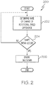
- the engine control 144 is further configured to determine if a shaft break has occurred. More specifically, the engine control 144 is configured, upon receipt of the fan rotational speed signal 146 and the turbine engine rotational speed signal 148, to determine if a shaft break has occurred. The manner in which the engine control 144 determines that a shaft break has occurred may also vary. One particular process is depicted in flowchart form in FIG. 2 , and with reference thereto will now be described.
- the engine control 144 upon initiation of the process 200, processes the fan rotational speed signal 146 and the turbine engine rotational speed signal 148 to determine the rate of change of the rotational speed difference between the sensed fan rotational speed and the sensed turbine engine rotational speed (202). The determined rate of change of the rotational speed difference is then used to determine whether a shaft break has occurred (204). If it is determined that a shaft break has occurred, then the engine 100 is shutdown and an alert may also be generated (206). If not, then the process 200 repeats. The manner in which the rate of change of the rotational speed difference is determined may vary, as may the manner in which the determination is made as to whether a shaft break has occurred. Some examples of how these determinations are made are described further below.
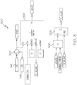
- FIG. 2 may be variously implemented. It will additionally be appreciated that the processor 146 in the engine control 144 may be configured to implement numerous and varied functional logic for carrying out the various implementations of the generalized process 200. Some example embodiments of the functional logic that the processor 146 may implement are depicted in FIGS. 3-8 , and will now be described, beginning with FIG. 3 .
- the functional logic 300 depicted in FIG. 3 includes a difference function 302, a derivative function 304, and a comparator 306.
- the difference function 302 subtracts the sensed turbine engine rotational speed (n2) 148 from the sensed fan rotational speed (n1) 146 to determine a rotational speed difference (n1mn2).
- the rotational speed difference (n1mn2) is supplied to the derivative function 304, which is implemented using a first order high-pass filter, to output the rate of change of the input. In this case, the rate of change of the rotational speed difference (n1mn2d).
- the derivative function 304 also smooths the rate of change for robust detection.
- the derivative function 304 implements a time-constant (Tau) that may be set to a predetermined value (C.N1MN2_TAU). Although this value may vary, in one particular embodiment, a value of 0.01 seconds is used. It will be appreciated that this value may be varied as needed or desired.
- Tau time-constant
- the rate of change of the rotational speed difference (n1mn2d) that is output by the derivative function 304 is supplied to the comparator 306, which compares this value to a pre-determined threshold value (C.N1MN2D_THRESH). If rate of change of the rotational speed difference (n1mn2d) is less than or equal to the predetermined threshold value (C.N1MN2D_THRESH), then it is determined that a broken shaft has occurred. As a result, a logical-1 is supplied to the S-input of a SET-RESET logic function 308, which in turn outputs a logical-1 to indicate that the engine 100 should be shutdown.
- the threshold value (C.N1MN2D_THRESH) may vary, and may be set to a desired value. In one particular embodiment a value of -150%/second is used. It will be appreciated that this value may also be varied as needed or desired.
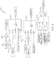
- This functional logic 400 includes the same functions as the previously described functional logic 300, but additionally includes a squaring function 402 a first-order lag filter 404, a second comparator 406, and AND-logic 408.
- the rate of change of rotational speed difference (n1mn2d) is supplied to the squaring function 402, which calculates the square of the rate of change of rotational speed difference, and supplies this value to the first-order lag filter 404.
- the second first-order lag filter 404 filters the square of the rate of change of rotational speed difference to provide a squared and filtered rate of change (n1mn2d_pwf).
- the first-order lag filter 404 also smooths the squared rate of change for robust detection, and also implements a time-constant (Tau) that may be set to a predetermined value (C.N1MN2TAU1).
- Tau time-constant
- this value may vary, in one particular embodiment, a value of 0.01 seconds is used. It will be appreciated that this value may be varied as needed or desired.
- the value (n1mn2d_pwf) output by the first-order lag filter 404 is compared, by the comparator 306, to a predetermined threshold value (C.N1MN2D_PWF_THRESH). If the squared and filtered rate of change (n1mn2d_pwf) is greater than or equal to the predetermined threshold value (C.N1MN2D_PWF_THRESH), and the rate of change of the rotational speed difference (n1mn2d) is negative (e.g., less than a predetermined negative threshold value (C.N1MN2D_DET), then it is determined that a shaft break has occurred.
- a predetermined threshold value C.N1MN2D_PWF_THRESH
- a logical-1 is supplied to the S-input of the SET-RESET logic function 308, which in turn outputs a logical-1 to indicate that the engine 100 should be shutdown.
- the predetermined threshold value (C.N1MN2D_PWF_THRESH) and the predetermined negative threshold value (C.N1MN2D_DET) may vary, and may be set to desired values. In one particular embodiment a value of 20,000% 2 /second 2 is used for the predetermined threshold value (C.N1MN2D_PWF_THRESH) and a value of -20%/second is used for the predetermined negative threshold value (C.N1MN2D_DET). It will be appreciated that these values may also be varied as needed or desired.
- FIG. 5 Another embodiment of the functional logic that the processor 146 may implement is depicted in FIG. 5 .
- This functional logic 500 includes the same functions as the previously described functional logic 400; however, instead of first calculating the square of the rate of change of rotational speed difference (n1mn2d) and then filtering this value, the rate of change of rotational speed difference (n1mn2d) is first filtered by the first-order lag filter 404 to provide a filtered rate of change. This value is then supplied to the squaring function 402, which calculates a square of the filtered rate of change to provide a filtered and squared rate of change (n1mn2d_fpw).
- the value (n1mn2d_fpw) output by the squaring function 402 is compared, by the comparator 306, to a predetermined threshold value (C.N1MN2D_FPW_THRESH). If the filtered and squared rate of change (n1mn2d_fpw) is greater than or equal to the predetermined threshold value (C.N1MN2D_FPW_THRESH), and the rate of change of the rotational speed difference (n1mn2d) is negative (e.g., less than the predetermined negative threshold value (C.N1MN2D_DET), then it is determined that a shaft break has occurred.
- a logical-1 is supplied to the S-input of the SET-RESET logic function 308, which in turn outputs a logical-1 to indicate that the engine 100 should be shutdown.
- the predetermined threshold value (C.N1MN2D_FPW_THRESH) and the predetermined negative threshold value (C.N1MN2D_DET) may vary, and may be set to desired values. In one particular embodiment a value of 15,000% 2 /second 2 is used for the predetermined threshold value (C.N1MN2D_FPW_THRESH) and a value of -20%/second is used for the predetermined negative threshold value (C.N1MN2D_DET). It will be appreciated that these values may also be varied as needed or desired.
- the functional logic 600 depicted in FIG. 6 implements a combination of the functional logics 400, 500 depicted in FIGS. 4 and 5 , and thus includes first and second squaring functions 402-1, 402-2, first and second first-order lag filters 404-1, 404-2, and a second difference function 602.
- the square of the rate of change of rotational speed difference (n1mn2d) is calculated using the first squaring function 402-1, and is then filtered through the first first-order lag filter 404-1 to provide the squared and filtered rate of change (n1mn2d_pwf).
- the rate of change of rotational speed difference (n1mn2d) is filtered by the second first-order lag filter 404-2 to provide a filtered rate of change.
- This value is then supplied to the second squaring function 402-2, which calculates the square of the filtered rate of change to provide the filtered and squared rate of change (n1mn2d_fpw).
- the squared and filtered rate of change (n1mn2d_pwf) and the filtered and squared rate of change (n1mn2d_fpw) are both supplied to the second difference function 602.
- the second difference function 602 subtracts the filtered and squared rate of change (n1mn2d_fpw) from the squared and filtered rate of change (n1mn2d_pwf) to provide what is referred to herein as a variance value (n1mn2dvar).
- the variance value (n1mn2dvar) is compared, by the comparator 306, to a predetermined threshold value (C.N1MN2DVAR_THRESH).
- n1mn2dvar the variance value (n1mn2dvar) is greater than or equal to the predetermined threshold value (C.N1MN2DVAR_THRESH), and the rate of change of the rotational speed difference (n1mn2d) is negative (e.g., less than the predetermined negative threshold value (C.N1MN2D_DET), then it is determined that a shaft break has occurred. As a result, a logical-1 is supplied to the S-input of the SET-RESET logic function 308, which in turn outputs a logical-1 to indicate that the engine 100 should be shutdown.
- the predetermined threshold value (C.N1MN2DVAR_THRESH) and the predetermined negative threshold value (C.N1MN2D_DET) may vary, and may be set to desired values. In one particular embodiment a value of 2,000% 2 /second 2 is used used for the predetermined threshold value (C.N1MN2DVAR_THRESH) and a value of - 20%/second is used for the predetermined negative threshold value (C.N1MN2D_DET). It will be appreciated that these values may also be varied as needed or desired.
- the functional logics 300-500 depicted in FIGS. 3-5 and described above are all configured to first determine the difference between the sensed fan rotational speed 146 and the sensed turbine engine rotational speed 148, and then determine the rate of change of the rotational speed difference. It will be appreciated, however, that the rate of change of the rotational speed difference may instead be determined by first determining the rate of change of the sensed fan rotational speed and rate of change of the sensed turbine rotational speed, and then determining the difference between the rate of change of the sensed fan rotational speed and the rate of change of the sensed turbine engine rotational speed. An example of this configuration is depicted in FIG. 7 , and with reference thereto will now be described.
- the functional logic 700 depicted in FIG. 7 includes the difference function 302, first and second derivative functions 304-1, 304-2, and the comparator 306. With this functional logic 700, however, the fan rotational speed is supplied to the first derivative function 304-1, and the turbine engine rotational speed is supplied to the second derivative function 304-2.
- the first derivative function 304-1 determines the fan rotational speed rate of change (n1dot)
- the second derivative function 304-2 determines the turbine engine rotational speed rate of change (n2dot).
- the first and second derivative functions 304-1, 304-2 also smooth the rate of changes for robust detection, and each implements a time-constant (Tau) that may be set to predetermined values (C.N1MN2_TAU). Although this value may vary, in one particular embodiment, a value of 0.01 seconds is used. It will be appreciated that this value may be varied as needed or desired.
- the difference function 302 then subtracts the turbine engine rotational speed rate of change (n2dot) from the fan rotational speed rate of change (n1dot) to determine the rate of change of the rotational speed difference (n1mn2d).
- the rate of change of the rotational speed difference (n1mn2d) is supplied to the comparator 306, which compares this value to a pre-determined threshold value (C.N1MN2D_THRESH). If rate of change of the rotational speed difference (n1mn2d) is less than or equal to the predetermined threshold value (C.N1MN2D_THRESH), then it is determined that a broken shaft has occurred.
- a logical-1 is supplied to the S-input of a SET-RESET logic function 308, which in turn outputs a logical-1 to indicate that the engine 100 should be shutdown.
- the threshold value (C.N1MN2D_THRESH) may vary, and may be set to a desired value. In one particular embodiment a value of -150%/second is used. It will be appreciated that this value may also be varied as needed or desired.
- the fan rotational speed rate of change (n1dot) and the turbine engine rotational speed rate of change (n2dot) are each corrected for ambient conditions, such temperature and/or pressure. This is accomplished by applying what are generally referred to as the theta correction ( ⁇ -correction) and/or the delta correction ( ⁇ -correction).
- the ⁇ -correction is an ambient temperature correction factor (which is equal to [(Total Air Temperature/Tref] 1/2 ) where common values for Tref may include 518.7°R amongst others, and the ⁇ -correction is an ambient pressure correction factor (which is equal to (Total Air Pressure/Pref), where common values for Pref may include 14.696 psia amongst others.
- the depicted functional logic 800 is identical to the functional logic 700 depicted in FIG.
- any of the functional logics 300-600 may be modified to implement ⁇ -correction and/or ⁇ -correction.
- the functional logics 300-600 depicted in FIGS. 3-6 can be modified to correct (either ⁇ -correction and/or ⁇ -correction) the sensed fan rotational speed (n1) and the sensed turbine rotational speed (n2) before the difference function 302 determines the rotational speed difference (n1mn2).
- the rate of change of the rotational speed difference (n1mn2d), the squared and filtered rate of change (n1mn2d_pwf), and/or the filtered and squared rate of change (n1mn2d_fpw) can be corrected (0-correction and/or ⁇ -correction).
- total air temperature is supplied from one or more temperature sensors 152 (only one depicted), and total air pressure is supplied from one or more pressure sensors 154 (only one depicted).
- the functional logics 300-800 depicted in FIGS. 3-8 and described above have been verified using previously acquired and stored severed shaft test data.
- the functional logics 300-800 have been verified using normal engine operation data associated with start, steady-state, acceleration, deceleration, and various maneuvers, and using various abnormal engine operating data.
- a relatively fast software sampling rate e.g., 2-6 millisecond
- a broken shaft can be detected in less than 0.04 seconds, which allows for proper engine shutdown.
- the turbofan gas turbine engine shaft break detections system and method uses existing fan speed (N1) and turbine speed (N2) sensors and does not rely on additional hardware.
- the system and method implements a relatively short sample rate detection loop, which eliminates the unreliability associated with currently known sensors.
- the system and method also provide various other advantages, such as, for example, reducing engine recurring costs associated with presently known detector assemblies, mounting hardware, and associated wiring; reducing engine weight; reducing maintenance costs; simplifying engine control system design (fault detection, signal selection and accommodation); and improving overall system reliability.
- Skilled artisans may implement the described functionality in varying ways for each particular application, but such implementation decisions should not be interpreted as causing a departure from the scope of the present invention.
- an embodiment of a system or a component may employ various integrated circuit components, e.g., memory elements, digital signal processing elements, logic elements, look-up tables, or the like, which may carry out a variety of functions under the control of one or more microprocessors or other control devices.
- integrated circuit components e.g., memory elements, digital signal processing elements, logic elements, look-up tables, or the like, which may carry out a variety of functions under the control of one or more microprocessors or other control devices.
- DSP digital signal processor
- ASIC application specific integrated circuit
- FPGA field programmable gate array
- a general-purpose processor may be a microprocessor, but in the alternative, the processor may be any conventional processor, controller, microcontroller, or state machine.
- a processor may also be implemented as a combination of computing devices, e.g., a combination of a DSP and a microprocessor, a plurality of microprocessors, one or more microprocessors in conjunction with a DSP core, or any other such configuration.
- a software module may reside in RAM memory, flash memory, ROM memory, EPROM memory, EEPROM memory, registers, hard disk, a removable disk, a CD-ROM, or any other form of storage medium known in the art.
- An exemplary storage medium is coupled to the processor such that the processor can read information from, and write information to, the storage medium.
- the storage medium may be integral to the processor.
- the processor and the storage medium may reside in an ASIC.
Landscapes
- Engineering & Computer Science (AREA)
- Mechanical Engineering (AREA)
- General Engineering & Computer Science (AREA)
- Chemical & Material Sciences (AREA)
- Combustion & Propulsion (AREA)
- Physics & Mathematics (AREA)
- General Physics & Mathematics (AREA)
- Control Of Positive-Displacement Air Blowers (AREA)
Claims (15)
- Wellenbrucherkennungssystem für Turbofan-Gasturbinentriebwerke für ein Turbofan-Triebwerk, das mindestens einen Bläser und eine Turbine umfasst, wobei das System Folgendes umfasst:einen Bläserdrehzahlsensor (142-1), der konfiguriert ist, um die Bläserdrehzahl zu erfassen und ein dafür repräsentatives Bläserdrehzahlsignal (146) zu liefern;einen Turbinentriebwerksdrehzahlsensor (142-2), der konfiguriert ist, um die Turbinendrehzahl zu erfassen und ein dafür repräsentatives Turbinentriebwerksdrehzahlsignal (148) zu liefern;einen Prozessor (144), der gekoppelt ist, um das Bläserdrehzahlsignal und das Turbinentriebwerksdrehzahlsignal zu empfangen, und dadurch gekennzeichnet ist, dass der Prozessor beim Empfang des Bläserdrehzahlsignals und des Turbinenantriebsdrehzahlsignals konfiguriert ist zum:Bestimmen einer Änderungsrate der Drehzahldifferenz zwischen der erfassten Bläserdrehzahl und der erfassten Turbinenantriebsdrehzahl; undBestimmen, dass ein Wellenbruch aufgetreten ist, zumindest teilweise basierend auf der Änderungsrate der Drehzahldifferenz.
- System nach Anspruch 1, wobei der Prozessor konfiguriert ist, um die Änderungsrate der Drehzahldifferenz zu bestimmen durch:Subtrahieren der erfassten Turbinenantriebsdrehzahl von der erfassten Bläserdrehzahl im Prozessor, um eine Drehzahldifferenz zu bestimmen; undBestimmen der Änderungsrate der Drehzahldifferenz im Prozessor.
- System nach Anspruch 2, wobei der Prozessor konfiguriert ist, um zu bestimmen, dass ein Wellenbruch aufgetreten ist, durch:Vergleichen der Änderungsrate der Drehzahldifferenz mit einem vorbestimmten Schwellenwert; undBestimmen, dass der Wellenbruch aufgetreten ist, wenn die Änderungsrate der Drehzahldifferenz kleiner oder gleich dem vorbestimmten Schwellenwert ist.
- System nach Anspruch 2, wobei der Prozessor konfiguriert ist, um die Änderungsrate der Drehzahldifferenz durch Filtern der Drehzahldifferenz durch einen Hochpassfilter erster Ordnung zu bestimmen.
- System nach Anspruch 1, wobei der Prozessor konfiguriert ist, um zu bestimmen, dass ein Wellenbruch aufgetreten ist durch:Berechnen eines Quadrats der Änderungsrate der Drehzahldifferenz;Filtern des Quadrats der Änderungsrate der Drehzahldifferenz durch einen Verzögerungsfilter erster Ordnung, um eine quadratische und gefilterte Änderungsrate bereitzustellen;Vergleichen der quadratischen und gefilterten Änderungsrate mit einem vorbestimmten Schwellenwert; undBestimmen, dass der Wellenbruch aufgetreten ist, wenn die quadratische und gefilterte Änderungsrate größer oder gleich dem vorbestimmten Schwellenwert ist.
- System nach Anspruch 1, wobei der Prozessor konfiguriert ist, um zu bestimmen, dass ein Wellenbruch aufgetreten ist durch:Filtern der Änderungsrate der Drehzahldifferenz durch einen Verzögerungsfilter erster Ordnung, um eine gefilterte Änderungsrate bereitzustellen;Berechnen eines Quadrats der gefilterten Änderungsrate, um eine gefilterte und quadratische Änderungsrate bereitzustellen;Vergleichen der gefilterten und der quadratischen Änderungsrate mit einem vorbestimmten Schwellenwert; undBestimmen, dass der Wellenbruch aufgetreten ist, wenn die gefilterte und quadratische Änderungsrate größer oder gleich dem vorbestimmten Schwellenwert ist.
- System nach Anspruch 1, wobei der Prozessor konfiguriert ist, um zu bestimmen, dass ein Wellenbruch aufgetreten ist durch:Berechnen eines Quadrats der Änderungsrate der Drehzahldifferenz;Filtern des Quadrats der Änderungsrate der Drehzahldifferenz durch einen ersten Verzögerungsfilter erster Ordnung, um eine quadratische und gefilterte Änderungsrate bereitzustellen;Filtern der Änderungsrate der Drehzahldifferenz durch einen zweiten Verzögerungsfilter erster Ordnung, um eine gefilterte Änderungsrate bereitzustellen;Berechnen eines Quadrats der gefilterten Änderungsrate, um eine gefilterte und quadratische Änderungsrate bereitzustellen;Subtrahieren der gefilterten und quadratischen Änderungsrate von der quadratischen und gefilterten Änderungsrate, um einen Varianzwert bereitzustellen;Vergleichen des Varianzwertes mit einem vorbestimmten Schwellenwert; undBestimmen, dass der Wellenbruch aufgetreten ist, wenn der Varianzwert größer oder gleich dem vorbestimmten Schwellenwert ist.
- System nach Anspruch 1, wobei der Prozessor ferner konfiguriert ist, um die erfasste Bläserdrehzahl und die erfasste Turbinenantriebsdrehzahl für mindestens eines von Temperatur und Druck zu korrigieren.
- System nach Anspruch 1, wobei der Prozessor konfiguriert ist, um die Änderungsrate der Drehzahldifferenz zu bestimmen durch:Bestimmen der Änderungsrate der Bläserdrehzahl im Prozessor;Bestimmen der Änderungsrate der Turbinenantriebsdrehzahl im Prozessor; undSubtrahieren der Änderungsrate der Turbinenantriebsdrehzahl von der Änderungsrate der Bläserdrehzahl im Prozessor.
- System nach Anspruch 9, wobei der Prozessor ferner konfiguriert ist, um die Änderungsrate der Bläserdrehzahl und die Änderungsrate der Turbinenantriebsdrehzahl für mindestens eines von Temperatur und Druck zu korrigieren.
- Verfahren (200) zum Erkennen eines Wellenbruchs in einem Turbofan-Gasturbinentriebwerk (100), wobei das Turbofan-Triebwerk mindestens einen Bläser und eine Turbine einschließt, wobei das Verfahren die folgenden Schritte umfasst:Erfassen der Bläserdrehzahl;Erfassen der Turbinendrehzahl; wobei das Verfahren dadurch gekennzeichnet ist, dass (202) in einem Prozessor (144) eine Änderungsrate der Drehzahldifferenz zwischen der erfassten Bläserdrehzahl und der erfassten Turbinendrehzahl bestimmt wird; undBestimmen (204) im Prozessor, dass ein Wellenbruch aufgetreten ist, zumindest teilweise basierend auf der Änderungsrate der Drehzahldifferenz.
- Verfahren nach Anspruch 11, wobei der Schritt des Bestimmens, dass ein Wellenbruch aufgetreten ist, Folgendes umfasst:Berechnen eines Quadrats der Änderungsrate der Drehzahldifferenz;Filtern des Quadrats der Änderungsrate der Drehzahldifferenz durch einen Verzögerungsfilter erster Ordnung, um eine quadratische und gefilterte Änderungsrate bereitzustellen;Vergleichen der quadratischen und gefilterten Änderungsrate mit einem vorbestimmten Schwellenwert; undBestimmen, dass der Wellenbruch aufgetreten ist, wenn die quadratische und gefilterte Änderungsrate größer oder gleich dem vorbestimmten Schwellenwert ist.
- Verfahren nach Anspruch 11, wobei der Schritt des Bestimmens, dass ein Wellenbruch aufgetreten ist, Folgendes umfasst:Filtern der Änderungsrate der Drehzahldifferenz durch einen Verzögerungsfilter erster Ordnung, um eine gefilterte Änderungsrate bereitzustellen;Berechnen eines Quadrats der gefilterten Änderungsrate, um eine gefilterte und quadratische Änderungsrate bereitzustellen;Vergleichen der gefilterten und der quadratischen Änderungsrate mit einem vorbestimmten Schwellenwert; undBestimmen, dass der Wellenbruch aufgetreten ist, wenn die gefilterte und quadratische Änderungsrate größer oder gleich dem vorbestimmten Schwellenwert ist.
- Verfahren nach Anspruch 11, wobei der Schritt des Bestimmens, dass ein Wellenbruch aufgetreten ist, Folgendes umfasst:Berechnen eines Quadrats der Änderungsrate der Drehzahldifferenz;Filtern des Quadrats der Änderungsrate der Drehzahldifferenz durch einen ersten Verzögerungsfilter erster Ordnung, um eine quadratische und gefilterte Änderungsrate bereitzustellen;Filtern der Änderungsrate der Drehzahldifferenz durch einen zweiten Verzögerungsfilter erster Ordnung, um eine gefilterte Änderungsrate bereitzustellen;Berechnen eines Quadrats der gefilterten Änderungsrate, um eine gefilterte und quadratische Änderungsrate bereitzustellen;Subtrahieren der gefilterten und quadratischen Änderungsrate von der quadratischen und gefilterten Änderungsrate, um einen Varianzwert bereitzustellen;Vergleichen des Varianzwertes mit einem vorbestimmten Schwellenwert; undBestimmen, dass der Wellenbruch aufgetreten ist, wenn der Varianzwert größer oder gleich dem vorbestimmten Schwellenwert ist.
- Verfahren nach Anspruch 11, welches weiter Folgendes aufweist:
Korrigieren der erfassten Bläserdrehzahl und der erfassten Turbinendrehzahl für mindestens eines von Temperatur und Druck.
Applications Claiming Priority (1)
| Application Number | Priority Date | Filing Date | Title |
|---|---|---|---|
| US15/237,834 US10989063B2 (en) | 2016-08-16 | 2016-08-16 | Turbofan gas turbine engine shaft break detection system and method |
Publications (2)
| Publication Number | Publication Date |
|---|---|
| EP3287609A1 EP3287609A1 (de) | 2018-02-28 |
| EP3287609B1 true EP3287609B1 (de) | 2020-04-08 |
Family
ID=59506131
Family Applications (1)
| Application Number | Title | Priority Date | Filing Date |
|---|---|---|---|
| EP17184140.6A Active EP3287609B1 (de) | 2016-08-16 | 2017-07-31 | System und verfahren zur erkennung des bruchs einer turbofan-welle |
Country Status (2)
| Country | Link |
|---|---|
| US (1) | US10989063B2 (de) |
| EP (1) | EP3287609B1 (de) |
Families Citing this family (11)
| Publication number | Priority date | Publication date | Assignee | Title |
|---|---|---|---|---|
| US20190292936A1 (en) * | 2018-03-26 | 2019-09-26 | Pratt & Whitney Canada Corp. | Method and system for detecting shear of a rotating shaft |
| WO2019217635A1 (en) | 2018-05-09 | 2019-11-14 | Abb Schweiz Ag | Turbine speed detection and use |
| US11168621B2 (en) | 2019-03-05 | 2021-11-09 | Pratt & Whitney Canada Corp. | Method and system for operating an engine in a multi-engine aircraft |
| CN113008567B (zh) * | 2019-12-04 | 2023-03-21 | 中国航发商用航空发动机有限责任公司 | 发动机高压轴断裂检测方法与装置、发动机系统 |
| GB202001602D0 (en) | 2020-02-06 | 2020-03-25 | Rolls Royce Plc | Detecting damage to a gas turbine engine |
| US12297782B2 (en) * | 2020-04-27 | 2025-05-13 | Hamilton Sundstrand Corporation | Detecting condition of a shaft of a gas turbofan aircraft engine |
| FR3111668B1 (fr) * | 2020-06-17 | 2023-04-07 | Airbus Helicopters | Procédé pour arrêter un moteur en survitesse, système et giravion associés |
| CN114608833B (zh) * | 2020-11-23 | 2024-02-02 | 中国航发商用航空发动机有限责任公司 | 涡扇发动机低压轴断裂检测方法及系统、涡扇发动机 |
| IT202000028520A1 (it) * | 2020-11-26 | 2022-05-26 | Ge Avio Srl | Sistema e metodo per la mitigazione di velocita' eccessiva di rotore |
| FR3134148B1 (fr) * | 2022-03-29 | 2024-05-24 | Safran Aircraft Engines | Turbopropulseur, aéronef et procédé de détection de défaillance associés |
| CN117848709B (zh) * | 2024-03-08 | 2024-05-14 | 成都晨发泰达航空科技股份有限公司 | 一种超高转数航空发动机涡轮转子超转测试装置及方法 |
Family Cites Families (18)
| Publication number | Priority date | Publication date | Assignee | Title |
|---|---|---|---|---|
| US4454754A (en) | 1982-05-26 | 1984-06-19 | Chandler Evans, Inc. | Engine failure detector |
| JPS5993905A (ja) | 1982-11-22 | 1984-05-30 | Hitachi Ltd | 回転機の主油ポンプ軸切損時の緊急停止装置 |
| GB8706905D0 (en) | 1987-03-24 | 1987-04-29 | Schlumberger Electronics Uk | Shaft monitoring system |
| GB9111906D0 (en) | 1991-06-04 | 1991-07-24 | Lucas Ind Plc | Shaft breakage detection system |
| US5303545A (en) * | 1992-10-05 | 1994-04-19 | United Technologies Corporation | Pressure based close loop thrust control in a turbofan engine |
| US5363317A (en) | 1992-10-29 | 1994-11-08 | United Technologies Corporation | Engine failure monitor for a multi-engine aircraft having partial engine failure and driveshaft failure detection |
| US5622045A (en) | 1995-06-07 | 1997-04-22 | Allison Engine Company, Inc. | System for detecting and accommodating gas turbine engine fan damage |
| US6176074B1 (en) | 1998-06-05 | 2001-01-23 | Pratt & Whitney Canada Corp. | Shaft decouple logic for gas turbine |
| DE19857552A1 (de) * | 1998-12-14 | 2000-06-15 | Rolls Royce Deutschland | Verfahren zum Erkennen eines Wellenbruches in einer Strömungskraftmaschine |
| US6607349B2 (en) | 2001-11-14 | 2003-08-19 | Honeywell International, Inc. | Gas turbine engine broken shaft detection system |
| FR2846379B1 (fr) | 2002-10-23 | 2005-01-21 | Snecma Moteurs | Systeme de decouplage par charge explosive d'une soufflante d'un turboreacteur |
| DE102004047892A1 (de) | 2004-10-01 | 2006-04-06 | Mtu Aero Engines Gmbh | Gasturbine und Verfahren zum Abschalten einer Gasturbine bei Identifikation eines Wellenbruchs |
| FR2923540B1 (fr) | 2007-11-13 | 2010-01-29 | Snecma | Dispositif de detection de rupture d'un arbre de turbomachine |
| US8954228B2 (en) | 2008-12-30 | 2015-02-10 | Rolls-Royce Corporation | Gas turbine engine failure detection |
| GB2488805A (en) * | 2011-03-09 | 2012-09-12 | Rolls Royce Plc | Shaft break detection |
| GB201121639D0 (en) | 2011-12-16 | 2012-01-25 | Rolls Royce Plc | Shaft break detection |
| US8825342B2 (en) | 2012-11-02 | 2014-09-02 | Bell Helicopter Textron Inc. | System and method of protecting an engine and other aircraft components from damage that may otherwise occur from a fuel control unit failure |
| FR2998058B1 (fr) | 2012-11-13 | 2016-02-05 | Microturbo | Dispositif et procede de protection d'un calculateur de turbo-machine d'aeronef contre les erreurs de mesure de vitesse |
-
2016
- 2016-08-16 US US15/237,834 patent/US10989063B2/en active Active
-
2017
- 2017-07-31 EP EP17184140.6A patent/EP3287609B1/de active Active
Non-Patent Citations (1)
| Title |
|---|
| None * |
Also Published As
| Publication number | Publication date |
|---|---|
| EP3287609A1 (de) | 2018-02-28 |
| US10989063B2 (en) | 2021-04-27 |
| US20180051585A1 (en) | 2018-02-22 |
Similar Documents
| Publication | Publication Date | Title |
|---|---|---|
| EP3287609B1 (de) | System und verfahren zur erkennung des bruchs einer turbofan-welle | |
| US4622808A (en) | Surge/stall cessation detection system | |
| EP3039270B1 (de) | Nachweis von flammendurchschlag bei einer gasturbine | |
| EP0418189B1 (de) | Feststellung und Zurückführung von Abreissgebiet/Pumpen einer Gasturbine | |
| US10184348B2 (en) | System and method for turbine blade clearance control | |
| EP3173890B1 (de) | Fehlerdetektionsverfahren und -systeme | |
| EP3147483B1 (de) | System und verfahren zur detektion von unkontrolliertem hohem schub in einem gasturbinenmotor | |
| EP3399155B1 (de) | Verfahren und system zum ausgleichen eines drehmomentsignal-verlusts | |
| EP3712737B1 (de) | Signalantwortüberwachung für turbinenmotoren | |
| US9695752B2 (en) | Engine-induced aircraft cabin resonance reduction system and method | |
| EP2993311B1 (de) | System und verfahren zur reduzierung von triebwerksinduzierter flugzeugkabinenresonanz | |
| EP3098510B1 (de) | System und verfahren zur berücksichtugung eines unkontrollierten hohen schubs in einem gasturbinenmotor | |
| EP3409926B1 (de) | Verfahren und system zur detektion eines hochtemperaturzustands einer gasturbine | |
| EP3904660B1 (de) | System und verfahren zur erkennung eines wellenereignisses an einem gasturbinen-triebwerk | |
| EP3106649B1 (de) | Steuerung einer flugzeuggasturbine ohne totaltemperatursensoren des flugzeugs | |
| EP3287625B1 (de) | Steuerungssystem und -verfahren zur vermeidung von verdichterpumpem eines gasturbinenmotors | |
| CN110887668A (zh) | 用于检测和适应扭矩信号的损失的方法和系统 |
Legal Events
| Date | Code | Title | Description |
|---|---|---|---|
| PUAI | Public reference made under article 153(3) epc to a published international application that has entered the european phase |
Free format text: ORIGINAL CODE: 0009012 |
|
| STAA | Information on the status of an ep patent application or granted ep patent |
Free format text: STATUS: REQUEST FOR EXAMINATION WAS MADE |
|
| 17P | Request for examination filed |
Effective date: 20170731 |
|
| AK | Designated contracting states |
Kind code of ref document: A1 Designated state(s): AL AT BE BG CH CY CZ DE DK EE ES FI FR GB GR HR HU IE IS IT LI LT LU LV MC MK MT NL NO PL PT RO RS SE SI SK SM TR |
|
| AX | Request for extension of the european patent |
Extension state: BA ME |
|
| GRAP | Despatch of communication of intention to grant a patent |
Free format text: ORIGINAL CODE: EPIDOSNIGR1 |
|
| STAA | Information on the status of an ep patent application or granted ep patent |
Free format text: STATUS: GRANT OF PATENT IS INTENDED |
|
| INTG | Intention to grant announced |
Effective date: 20191112 |
|
| GRAS | Grant fee paid |
Free format text: ORIGINAL CODE: EPIDOSNIGR3 |
|
| GRAA | (expected) grant |
Free format text: ORIGINAL CODE: 0009210 |
|
| STAA | Information on the status of an ep patent application or granted ep patent |
Free format text: STATUS: THE PATENT HAS BEEN GRANTED |
|
| AK | Designated contracting states |
Kind code of ref document: B1 Designated state(s): AL AT BE BG CH CY CZ DE DK EE ES FI FR GB GR HR HU IE IS IT LI LT LU LV MC MK MT NL NO PL PT RO RS SE SI SK SM TR |
|
| REG | Reference to a national code |
Ref country code: CH Ref legal event code: EP Ref country code: AT Ref legal event code: REF Ref document number: 1254660 Country of ref document: AT Kind code of ref document: T Effective date: 20200415 |
|
| REG | Reference to a national code |
Ref country code: DE Ref legal event code: R096 Ref document number: 602017014255 Country of ref document: DE |
|
| REG | Reference to a national code |
Ref country code: IE Ref legal event code: FG4D |
|
| REG | Reference to a national code |
Ref country code: NL Ref legal event code: MP Effective date: 20200408 |
|
| REG | Reference to a national code |
Ref country code: LT Ref legal event code: MG4D |
|
| PG25 | Lapsed in a contracting state [announced via postgrant information from national office to epo] |
Ref country code: IS Free format text: LAPSE BECAUSE OF FAILURE TO SUBMIT A TRANSLATION OF THE DESCRIPTION OR TO PAY THE FEE WITHIN THE PRESCRIBED TIME-LIMIT Effective date: 20200808 Ref country code: SE Free format text: LAPSE BECAUSE OF FAILURE TO SUBMIT A TRANSLATION OF THE DESCRIPTION OR TO PAY THE FEE WITHIN THE PRESCRIBED TIME-LIMIT Effective date: 20200408 Ref country code: FI Free format text: LAPSE BECAUSE OF FAILURE TO SUBMIT A TRANSLATION OF THE DESCRIPTION OR TO PAY THE FEE WITHIN THE PRESCRIBED TIME-LIMIT Effective date: 20200408 Ref country code: NO Free format text: LAPSE BECAUSE OF FAILURE TO SUBMIT A TRANSLATION OF THE DESCRIPTION OR TO PAY THE FEE WITHIN THE PRESCRIBED TIME-LIMIT Effective date: 20200708 Ref country code: PT Free format text: LAPSE BECAUSE OF FAILURE TO SUBMIT A TRANSLATION OF THE DESCRIPTION OR TO PAY THE FEE WITHIN THE PRESCRIBED TIME-LIMIT Effective date: 20200817 Ref country code: GR Free format text: LAPSE BECAUSE OF FAILURE TO SUBMIT A TRANSLATION OF THE DESCRIPTION OR TO PAY THE FEE WITHIN THE PRESCRIBED TIME-LIMIT Effective date: 20200709 Ref country code: NL Free format text: LAPSE BECAUSE OF FAILURE TO SUBMIT A TRANSLATION OF THE DESCRIPTION OR TO PAY THE FEE WITHIN THE PRESCRIBED TIME-LIMIT Effective date: 20200408 Ref country code: LT Free format text: LAPSE BECAUSE OF FAILURE TO SUBMIT A TRANSLATION OF THE DESCRIPTION OR TO PAY THE FEE WITHIN THE PRESCRIBED TIME-LIMIT Effective date: 20200408 |
|
| REG | Reference to a national code |
Ref country code: AT Ref legal event code: MK05 Ref document number: 1254660 Country of ref document: AT Kind code of ref document: T Effective date: 20200408 |
|
| PG25 | Lapsed in a contracting state [announced via postgrant information from national office to epo] |
Ref country code: BG Free format text: LAPSE BECAUSE OF FAILURE TO SUBMIT A TRANSLATION OF THE DESCRIPTION OR TO PAY THE FEE WITHIN THE PRESCRIBED TIME-LIMIT Effective date: 20200708 Ref country code: LV Free format text: LAPSE BECAUSE OF FAILURE TO SUBMIT A TRANSLATION OF THE DESCRIPTION OR TO PAY THE FEE WITHIN THE PRESCRIBED TIME-LIMIT Effective date: 20200408 Ref country code: RS Free format text: LAPSE BECAUSE OF FAILURE TO SUBMIT A TRANSLATION OF THE DESCRIPTION OR TO PAY THE FEE WITHIN THE PRESCRIBED TIME-LIMIT Effective date: 20200408 Ref country code: HR Free format text: LAPSE BECAUSE OF FAILURE TO SUBMIT A TRANSLATION OF THE DESCRIPTION OR TO PAY THE FEE WITHIN THE PRESCRIBED TIME-LIMIT Effective date: 20200408 |
|
| PG25 | Lapsed in a contracting state [announced via postgrant information from national office to epo] |
Ref country code: AL Free format text: LAPSE BECAUSE OF FAILURE TO SUBMIT A TRANSLATION OF THE DESCRIPTION OR TO PAY THE FEE WITHIN THE PRESCRIBED TIME-LIMIT Effective date: 20200408 |
|
| REG | Reference to a national code |
Ref country code: DE Ref legal event code: R097 Ref document number: 602017014255 Country of ref document: DE |
|
| PG25 | Lapsed in a contracting state [announced via postgrant information from national office to epo] |
Ref country code: SM Free format text: LAPSE BECAUSE OF FAILURE TO SUBMIT A TRANSLATION OF THE DESCRIPTION OR TO PAY THE FEE WITHIN THE PRESCRIBED TIME-LIMIT Effective date: 20200408 Ref country code: EE Free format text: LAPSE BECAUSE OF FAILURE TO SUBMIT A TRANSLATION OF THE DESCRIPTION OR TO PAY THE FEE WITHIN THE PRESCRIBED TIME-LIMIT Effective date: 20200408 Ref country code: AT Free format text: LAPSE BECAUSE OF FAILURE TO SUBMIT A TRANSLATION OF THE DESCRIPTION OR TO PAY THE FEE WITHIN THE PRESCRIBED TIME-LIMIT Effective date: 20200408 Ref country code: DK Free format text: LAPSE BECAUSE OF FAILURE TO SUBMIT A TRANSLATION OF THE DESCRIPTION OR TO PAY THE FEE WITHIN THE PRESCRIBED TIME-LIMIT Effective date: 20200408 Ref country code: IT Free format text: LAPSE BECAUSE OF FAILURE TO SUBMIT A TRANSLATION OF THE DESCRIPTION OR TO PAY THE FEE WITHIN THE PRESCRIBED TIME-LIMIT Effective date: 20200408 Ref country code: CZ Free format text: LAPSE BECAUSE OF FAILURE TO SUBMIT A TRANSLATION OF THE DESCRIPTION OR TO PAY THE FEE WITHIN THE PRESCRIBED TIME-LIMIT Effective date: 20200408 Ref country code: RO Free format text: LAPSE BECAUSE OF FAILURE TO SUBMIT A TRANSLATION OF THE DESCRIPTION OR TO PAY THE FEE WITHIN THE PRESCRIBED TIME-LIMIT Effective date: 20200408 Ref country code: ES Free format text: LAPSE BECAUSE OF FAILURE TO SUBMIT A TRANSLATION OF THE DESCRIPTION OR TO PAY THE FEE WITHIN THE PRESCRIBED TIME-LIMIT Effective date: 20200408 |
|
| PLBE | No opposition filed within time limit |
Free format text: ORIGINAL CODE: 0009261 |
|
| STAA | Information on the status of an ep patent application or granted ep patent |
Free format text: STATUS: NO OPPOSITION FILED WITHIN TIME LIMIT |
|
| PG25 | Lapsed in a contracting state [announced via postgrant information from national office to epo] |
Ref country code: SK Free format text: LAPSE BECAUSE OF FAILURE TO SUBMIT A TRANSLATION OF THE DESCRIPTION OR TO PAY THE FEE WITHIN THE PRESCRIBED TIME-LIMIT Effective date: 20200408 Ref country code: PL Free format text: LAPSE BECAUSE OF FAILURE TO SUBMIT A TRANSLATION OF THE DESCRIPTION OR TO PAY THE FEE WITHIN THE PRESCRIBED TIME-LIMIT Effective date: 20200408 Ref country code: MC Free format text: LAPSE BECAUSE OF FAILURE TO SUBMIT A TRANSLATION OF THE DESCRIPTION OR TO PAY THE FEE WITHIN THE PRESCRIBED TIME-LIMIT Effective date: 20200408 |
|
| REG | Reference to a national code |
Ref country code: CH Ref legal event code: PL |
|
| 26N | No opposition filed |
Effective date: 20210112 |
|
| REG | Reference to a national code |
Ref country code: BE Ref legal event code: MM Effective date: 20200731 |
|
| PG25 | Lapsed in a contracting state [announced via postgrant information from national office to epo] |
Ref country code: FR Free format text: LAPSE BECAUSE OF NON-PAYMENT OF DUE FEES Effective date: 20200731 Ref country code: CH Free format text: LAPSE BECAUSE OF NON-PAYMENT OF DUE FEES Effective date: 20200731 Ref country code: LI Free format text: LAPSE BECAUSE OF NON-PAYMENT OF DUE FEES Effective date: 20200731 Ref country code: LU Free format text: LAPSE BECAUSE OF NON-PAYMENT OF DUE FEES Effective date: 20200731 |
|
| PG25 | Lapsed in a contracting state [announced via postgrant information from national office to epo] |
Ref country code: BE Free format text: LAPSE BECAUSE OF NON-PAYMENT OF DUE FEES Effective date: 20200731 Ref country code: SI Free format text: LAPSE BECAUSE OF FAILURE TO SUBMIT A TRANSLATION OF THE DESCRIPTION OR TO PAY THE FEE WITHIN THE PRESCRIBED TIME-LIMIT Effective date: 20200408 |
|
| PG25 | Lapsed in a contracting state [announced via postgrant information from national office to epo] |
Ref country code: IE Free format text: LAPSE BECAUSE OF NON-PAYMENT OF DUE FEES Effective date: 20200731 |
|
| GBPC | Gb: european patent ceased through non-payment of renewal fee |
Effective date: 20210731 |
|
| PG25 | Lapsed in a contracting state [announced via postgrant information from national office to epo] |
Ref country code: GB Free format text: LAPSE BECAUSE OF NON-PAYMENT OF DUE FEES Effective date: 20210731 |
|
| PG25 | Lapsed in a contracting state [announced via postgrant information from national office to epo] |
Ref country code: TR Free format text: LAPSE BECAUSE OF FAILURE TO SUBMIT A TRANSLATION OF THE DESCRIPTION OR TO PAY THE FEE WITHIN THE PRESCRIBED TIME-LIMIT Effective date: 20200408 Ref country code: MT Free format text: LAPSE BECAUSE OF FAILURE TO SUBMIT A TRANSLATION OF THE DESCRIPTION OR TO PAY THE FEE WITHIN THE PRESCRIBED TIME-LIMIT Effective date: 20200408 Ref country code: CY Free format text: LAPSE BECAUSE OF FAILURE TO SUBMIT A TRANSLATION OF THE DESCRIPTION OR TO PAY THE FEE WITHIN THE PRESCRIBED TIME-LIMIT Effective date: 20200408 |
|
| PG25 | Lapsed in a contracting state [announced via postgrant information from national office to epo] |
Ref country code: MK Free format text: LAPSE BECAUSE OF FAILURE TO SUBMIT A TRANSLATION OF THE DESCRIPTION OR TO PAY THE FEE WITHIN THE PRESCRIBED TIME-LIMIT Effective date: 20200408 |
|
| P01 | Opt-out of the competence of the unified patent court (upc) registered |
Effective date: 20230525 |
|
| PGFP | Annual fee paid to national office [announced via postgrant information from national office to epo] |
Ref country code: DE Payment date: 20250728 Year of fee payment: 9 |