EP3287619A1 - Variabler düsenmechanismus und turbolader mit variabler geometrie - Google Patents
Variabler düsenmechanismus und turbolader mit variabler geometrie Download PDFInfo
- Publication number
- EP3287619A1 EP3287619A1 EP15911429.7A EP15911429A EP3287619A1 EP 3287619 A1 EP3287619 A1 EP 3287619A1 EP 15911429 A EP15911429 A EP 15911429A EP 3287619 A1 EP3287619 A1 EP 3287619A1
- Authority
- EP
- European Patent Office
- Prior art keywords
- turbine rotor
- annular member
- exhaust gas
- nozzle mechanism
- flow passage
- Prior art date
- Legal status (The legal status is an assumption and is not a legal conclusion. Google has not performed a legal analysis and makes no representation as to the accuracy of the status listed.)
- Granted
Links
- 230000007246 mechanism Effects 0.000 title claims description 48
- 230000002093 peripheral effect Effects 0.000 claims abstract description 54
- 230000035882 stress Effects 0.000 description 39
- 238000010586 diagram Methods 0.000 description 26
- 230000008646 thermal stress Effects 0.000 description 19
- 230000007704 transition Effects 0.000 description 14
- 238000001816 cooling Methods 0.000 description 10
- 230000008859 change Effects 0.000 description 7
- 239000012141 concentrate Substances 0.000 description 6
- 230000015572 biosynthetic process Effects 0.000 description 5
- 238000005266 casting Methods 0.000 description 5
- 238000003754 machining Methods 0.000 description 5
- 230000000694 effects Effects 0.000 description 4
- 238000010438 heat treatment Methods 0.000 description 4
- PXHVJJICTQNCMI-UHFFFAOYSA-N Nickel Chemical compound [Ni] PXHVJJICTQNCMI-UHFFFAOYSA-N 0.000 description 3
- 239000002184 metal Substances 0.000 description 3
- 229910052751 metal Inorganic materials 0.000 description 3
- 238000005192 partition Methods 0.000 description 3
- 230000035515 penetration Effects 0.000 description 3
- 230000002123 temporal effect Effects 0.000 description 3
- 229910045601 alloy Inorganic materials 0.000 description 2
- 239000000956 alloy Substances 0.000 description 2
- 230000000149 penetrating effect Effects 0.000 description 2
- 230000006835 compression Effects 0.000 description 1
- 238000007906 compression Methods 0.000 description 1
- 230000009429 distress Effects 0.000 description 1
- 238000012423 maintenance Methods 0.000 description 1
- 239000000463 material Substances 0.000 description 1
- 238000012986 modification Methods 0.000 description 1
- 230000004048 modification Effects 0.000 description 1
- 229910052759 nickel Inorganic materials 0.000 description 1
- 230000008439 repair process Effects 0.000 description 1
- 230000003252 repetitive effect Effects 0.000 description 1
- 238000000638 solvent extraction Methods 0.000 description 1
- 239000010935 stainless steel Substances 0.000 description 1
- 229910001220 stainless steel Inorganic materials 0.000 description 1
Images










Classifications
-
- F—MECHANICAL ENGINEERING; LIGHTING; HEATING; WEAPONS; BLASTING
- F02—COMBUSTION ENGINES; HOT-GAS OR COMBUSTION-PRODUCT ENGINE PLANTS
- F02B—INTERNAL-COMBUSTION PISTON ENGINES; COMBUSTION ENGINES IN GENERAL
- F02B37/00—Engines characterised by provision of pumps driven at least for part of the time by exhaust
- F02B37/12—Control of the pumps
- F02B37/24—Control of the pumps by using pumps or turbines with adjustable guide vanes
-
- F—MECHANICAL ENGINEERING; LIGHTING; HEATING; WEAPONS; BLASTING
- F01—MACHINES OR ENGINES IN GENERAL; ENGINE PLANTS IN GENERAL; STEAM ENGINES
- F01D—NON-POSITIVE DISPLACEMENT MACHINES OR ENGINES, e.g. STEAM TURBINES
- F01D17/00—Regulating or controlling by varying flow
- F01D17/10—Final actuators
- F01D17/12—Final actuators arranged in stator parts
- F01D17/14—Final actuators arranged in stator parts varying effective cross-sectional area of nozzles or guide conduits
- F01D17/16—Final actuators arranged in stator parts varying effective cross-sectional area of nozzles or guide conduits by means of nozzle vanes
- F01D17/165—Final actuators arranged in stator parts varying effective cross-sectional area of nozzles or guide conduits by means of nozzle vanes for radial flow, i.e. the vanes turning around axes which are essentially parallel to the rotor centre line
-
- F—MECHANICAL ENGINEERING; LIGHTING; HEATING; WEAPONS; BLASTING
- F05—INDEXING SCHEMES RELATING TO ENGINES OR PUMPS IN VARIOUS SUBCLASSES OF CLASSES F01-F04
- F05D—INDEXING SCHEME FOR ASPECTS RELATING TO NON-POSITIVE-DISPLACEMENT MACHINES OR ENGINES, GAS-TURBINES OR JET-PROPULSION PLANTS
- F05D2220/00—Application
- F05D2220/40—Application in turbochargers
-
- Y—GENERAL TAGGING OF NEW TECHNOLOGICAL DEVELOPMENTS; GENERAL TAGGING OF CROSS-SECTIONAL TECHNOLOGIES SPANNING OVER SEVERAL SECTIONS OF THE IPC; TECHNICAL SUBJECTS COVERED BY FORMER USPC CROSS-REFERENCE ART COLLECTIONS [XRACs] AND DIGESTS
- Y02—TECHNOLOGIES OR APPLICATIONS FOR MITIGATION OR ADAPTATION AGAINST CLIMATE CHANGE
- Y02T—CLIMATE CHANGE MITIGATION TECHNOLOGIES RELATED TO TRANSPORTATION
- Y02T10/00—Road transport of goods or passengers
- Y02T10/10—Internal combustion engine [ICE] based vehicles
- Y02T10/12—Improving ICE efficiencies
Definitions
- the present disclosure relates to a variable nozzle mechanism and a variable geometry turbocharger.
- variable nozzle mechanism of the variable geometry turbocharger is for adjusting the flow passage area of exhaust gas inside a turbine casing to change the flow velocity and the pressure of exhaust gas to turbine blades, so as to enhance the effect of supercharging.
- variable nozzle mechanism normally includes: a first annular member 012; a second annular member 14 disposed so as to face the first annular member and forming an annular exhaust gas flow passage 24 for guiding exhaust gas from a scroll flow passage 10 formed on the radially outer side of a turbine rotor 2 of the turbocharger to the turbine rotor between the first annular member and the second annular member; and a plurality of nozzle vanes 16 disposed between the first annular member and the second annular member so as to be rotatable and capable of adjusting the flow passage area of the exhaust gas flow passage.
- Patent Document 1 discloses a turbocharger comprising a variable nozzle mechanism, wherein an annular partition wall member for partitioning a scroll flow passage and a link chamber is disposed around a nozzle ring (corresponding to the above first annular member).
- the annular partition wall member is formed of a member separate from a turbine housing, for preventing cracks formed on the partition wall member from reaching the turbine housing.
- Patent Document 1 JP2015-34470A
- the first annular member 012 of the variable nozzle mechanism is exposed to high-temperature exhaust gas flowing through the exhaust gas flow passage 24, and thus the temperature distribution and the thermal stress distribution of the first annular member 012 change due to the change in the temperature and the flow rate of exhaust gas flowing through the exhaust gas flow passage 24 that accompanies output variation of the engine.
- the present inventors analyzed variation of the metal temperature and the stress of an inner peripheral edge 026 of the first annular member 012 in a period from heating transition to cooling transition of the first annular member 012.
- FIGs. 20 and 21 show the analysis result.
- FIG. 20 is a diagram showing an example of stress distribution of the inner peripheral edge 026 of the first annular member 012 at the time of cooling transition of the first annular member 012.
- FIG. 21 is a diagram showing an example of variation of the metal temperature and the stress, at location Q, of the inner peripheral edge 026 in FIG. 20 .
- a penetration crack Cr may be formed as shown in FIG. 22 , penetrating through the first annular member 012 from the inner peripheral edge 026 to a support hole 30. Such a penetration crack Cr may affect the rotational movement of the nozzle vanes 16 and the gas flow of the exhaust gas flow passage 24.
- the exhaust gas temperature of a turbocharger for a gasoline engine rises higher than that of a diesel engine, and thus thermal stress is more likely to increase, and thermal fatigue cracks are more likely to occur.
- first annular member 012 of nickel-based alloy having a high-temperature fatigue strength to restrict generation of thermal fatigue cracks may increase the costs and reduce the price competitiveness of the product.
- Patent Document 1 does not disclose any configuration for suppressing generation of fatigue damage in the vicinity of the inner peripheral edge of the first annular member, and does not even disclose the problem of generation of fatigue damage in the vicinity of the inner peripheral edge.
- the present invention was made in view of the above described typical problem, and an object is to provide a variable nozzle mechanism capable of suppressing generation of fatigue cracks that penetrate from an inner peripheral edge to a support hole, for a first annular member forming an exhaust gas flow passage in a variable nozzle mechanism, and a variable geometry turbocharger having the same.
- variable geometry turbocharger described in the above (11)
- generation of such a fatigue crack that penetrates through from the inner peripheral edge to a support hole is suppressed, and thus it is possible to reduce efforts and time required to perform maintenance such as repair and replacement of the first annular member.
- variable nozzle mechanism capable of suppressing generation of fatigue cracks that penetrate from an inner peripheral edge to a support hole, for a first annular member forming an exhaust gas flow passage in a variable nozzle mechanism, and a variable geometry turbocharger having the same.
- an expression of relative or absolute arrangement such as “in a direction”, “along a direction”, “parallel”, “orthogonal”, “centered”, “concentric” and “coaxial” shall not be construed as indicating only the arrangement in a strict literal sense, but also includes a state where the arrangement is relatively displaced by a tolerance, or by an angle or a distance whereby it is possible to achieve the same function.
- an expression of an equal state such as “same” “equal” and “uniform” shall not be construed as indicating only the state in which the feature is strictly equal, but also includes a state in which there is a tolerance or a difference that can still achieve the same function.
- an expression of a shape such as a rectangular shape or a cylindrical shape shall not be construed as only the geometrically strict shape, but also includes a shape with unevenness or chamfered corners within the range in which the same effect can be achieved.
- FIG. 1 is a partial schematic diagram of a cross section, taken along a rotational axis O, of a variable geometry turbocharger 100 according to an embodiment of the present invention.
- the variable geometry turbocharger 100 includes a turbine rotor 2 disposed coaxially with a non-depicted compressor, a turbine casing 4 that houses the turbine rotor 2, a bearing casing 6 that houses a non-depicted bearing supporting the turbine rotor 2 rotatably, and a variable nozzle mechanism 8 disposed between the turbine casing 4 and the bearing casing 6.
- the turbine casing 4 has a scroll flow passage 10 formed on the radially outer side of the turbine rotor 2, and exhaust gas from a non-depicted engine is supplied to the turbine rotor 2 via the variable nozzle mechanism 8 after passing through the scroll flow passage 10.
- the variable nozzle mechanism 8 includes a first annular member 12 (nozzle mount), a second annular member 14 (nozzle plate), a plurality of nozzle vanes 16, a plurality of lever plates 18, a drive ring 20, a plurality of nozzle supports 22, and a back plate 23.
- the first annular member 12 is an annular plate disposed on the radially outer side of the turbine rotor 2, and is configured to support the plurality of nozzle vanes 16 rotatably.
- the first annular member 12 has a plurality of support holes 30 (through holes) for supporting respective shaft portions 16a of the plurality of nozzle vanes 16 rotatably.
- the plurality of support holes 30 are disposed at intervals in the circumferential direction of the turbine rotor 2.
- the second annular member 14 is an annular plate disposed so as to face the first annular member 12, and is configured to form an exhaust gas flow passage 24 having an annular shape between the first annular member 12 and the second annular member 14, for guiding exhaust gas from the scroll flow passage 10 to the turbine rotor 2.
- the first annular member 12 constitutes a hub-side wall 32 of the exhaust gas flow passage 24, while the second annular member 14 constitutes a shroud-side wall 34 of the exhaust gas flow passage 24.
- the first end side of the nozzle support 22 is inserted through a through hole 36 formed on the first annular member 12.
- the second end side of the nozzle support 22 is inserted through a through hole 38 formed on the second annular member 14.
- the first annular member 12 and the second annular member 14 are coupled by the plurality of nozzle supports 22.
- the inner peripheral edge 26 of the first annular member 12 has, on the side of the exhaust gas flow passage 24, an annular protruding portion 42 protruding inward in the radial direction of the turbine rotor 2.
- a back plate 23 is disposed between the back face of the turbine rotor 2 and the bearing casing 6, so that exhaust gas flowing from the exhaust gas flow passage 24 to the turbine rotor 2 does not leak toward the back side of the first annular member 12 (opposite to the exhaust gas flow passage 24) through the radially inner side of the first annular member 12.
- the back plate 23 is in contact with the annular protruding portion 42 at one end side in the axial direction, and is in contact with the bearing casing 6 at the other end side in the axial direction.
- the plurality of nozzle vanes 16 are disposed between the first annular member 12 and the second annular member 14, and supported rotatably in the support holes 30 of the first annular member 12.
- the variable nozzle mechanism 8 is configured to adjust the flow passage area of the exhaust gas flow passage 24 by changing the vane angle of the plurality of nozzle vanes 16.
- the drive ring 20 is rotary driven by a driving force transmitted from a non-depicted actuator.
- the lever plates 18 being in engagement with the drive ring 20 rotate the shaft portions 16a of the nozzle vanes 16, and as a result, the nozzle vanes 16 rotate to change the vane angle of the nozzle vanes 16.
- FIG. 2 is a diagram of the first annular member 12 (12A) according to an embodiment, as seen in the axial direction of the turbine rotor 2 from the side of the exhaust gas flow passage 24.
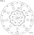
- FIG. 3 is a diagram of the first annular member 12 (12A) according to an embodiment, as seen in the axial direction of the turbine rotor 2 from the side of the exhaust gas flow passage 24.
- FIG. 4 is a partial enlarged view of the first annular member 12 (12A).
- FIG. 5 is a partial perspective view of the first annular member 12 (12A).
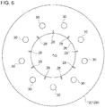
- FIG. 6 is a diagram of the first annular member 12 (12B) according to an embodiment, as seen in the axial direction of the turbine rotor 2 from the side of the exhaust gas flow passage 24.
- FIG. 1 is a diagram of the first annular member 12 (12A) according to an embodiment, as seen in the axial direction of the turbine rotor 2 from the side of the exhaust gas flow passage 24.
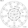
- FIG. 7 is a diagram of the first annular member 12 (12B) according to an embodiment, as seen in the axial direction of the turbine rotor 2 from the side of the exhaust gas flow passage 24.
- FIG. 8 is a partial enlarged view of the first annular member 12 (12A).
- FIG. 9 is a partial perspective view of the first annular member 12 (12B).
- the above through holes 36, 38 are not shown for the sake of convenience.
- the inner peripheral edge 26 of the first annular member 12 (12A, 12B) comprises a plurality of first inner edge portions 26a belonging to the angular range A in which the support holes 30 exist in the circumferential direction of the turbine rotor 2, and a plurality of second inner edge portions 26b belonging to the angular range B in which the support holes 30 do not exist in the circumferential direction of the turbine rotor 2.
- At least one second inner edge portion 26b (each of the plurality of second inner edge portions 26b in the exemplary embodiment shown in the drawings) among the plurality of second inner edge portions 26b has a recess portion 28 recessed outward in the radial direction of the turbine rotor 2.
- the recess portion 28 is disposed next to the exhaust gas flow passage 24, and extends in the axial direction of the turbine rotor 2 from the side of the exhaust gas flow passage 24.
- turbocharger 100 is a turbocharger for a gasoline engine, it is possible to suppress generation of such a fatigue crack that penetrates from the inner peripheral edge 26 to a support hole 30, even if the first annular member 12 is not made of Ni-based alloy but of stainless steel.
- each of the recess portions 28 is formed into an arc shape as seen in the axial direction of the turbine rotor 2. With such a configuration, stress is generated in a relatively uniform manner inside the recess portion 28 having an arc shape, and thus it is possible to suppress generation of a crack from the recess portion 28.
- each of the recess portions 28 is formed into a linear shape (rectangular shape) as seen in the axial direction of the turbine rotor 2.
- the recess portions 28 can be formed easily by machining, for instance.
- each of the recess portions 28 is formed at the center position P of the angular range B in which the support holes 30 do not exist in the circumferential direction of the turbine rotor 2. That is, each of the recess portions 28 is formed at such a position that the angular range C in which the recess portions 28 exist in the circumferential direction of the turbine rotor 2 includes the center position of the angular range B in the circumferential direction of the turbine rotor 2.
- the recess portions 28 where the stress concentrates are formed at positions away from the support holes 30, and thus it is possible to reduce thermal stress effectively at the first inner edge portions 26a belonging to the angular range A in which the support holes 30 exist.
- each of the recess portions 28 is formed on an annular protruding portion 42.
- the thickness of the annular protruding portion 42 in the axial direction of the turbine rotor 2 is likely to be thin. Also in this case, with the recess portions 28 disposed on the annular protruding portion 42, it is possible to suppress generation of such a fatigue crack that penetrates from the annular protruding portion 42 of the inner peripheral edge 26 to a support hole 30.
- each of the recess portions 28 is formed so as to penetrate the annular protruding portion 42 of the first annular member 12 in the axial direction of the turbine rotor 2. With such a configuration, it is possible to suppress generation of such a fatigue crack that penetrates from the inner peripheral edge 26 to a support hole 30 with a simple configuration.
- FIG. 10 is a stress distribution diagram showing an example of thermal stress generated in the first annular member 12 (12A) on cooling transition of the first annular member 12 (12A) (e.g. when the exhaust gas temperature and the exhaust gas flow rate of the exhaust gas flow passage 24 decrease due to a decrease in the engine output).
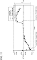
- FIG. 11 is a stress history chart showing the temporal change of stress generated at the same location Q (see FIGs. 10 and 21 ) of a first inner edge portion 26a, for a typical example shown in FIGs. 21 and the like and the embodiment (the first annular member 12 (12A) with the recess portion 28).
- FIG. 11 shows the temporal change of the above stress in a period from heating transition (e.g. when the exhaust gas temperature and the exhaust gas flow rate of the exhaust gas flow passage increase due to an increase in the engine output) to cooling transition (e.g. when the exhaust gas temperature and the exhaust gas flow rate of the exhaust gas flow passage decrease due to a decrease in the engine output).
- a negative stress is generated in the inner peripheral edge 26 (i.e., a compression stress is generated in the first inner edge portion 26a), and at the time of cooling transition, a positive stress is generated (a tension stress is generated in the first inner edge portion 26a).
- a tension stress is generated in the first inner edge portion 26a.
- it is possible to narrow the stress range S which is a difference between the maximum and the minimum of stress at the same location Q belonging to the first inner edge portion 26a, as compared to a typical case. Accordingly, it is possible to extend the fatigue lifetime of the first inner edge portion 26a, and to suppress generation of such a fatigue crack that penetrates from the inner peripheral edge 26 to a support hole 30.
- FIG. 12 is a stress distribution diagram showing an example of thermal stress generated in the first annular member 12 (12B) on cooling transition of the first annular member 12 (12B) (e.g. when the exhaust gas temperature and the exhaust gas flow rate of the exhaust gas flow passage 24 decrease due to a decrease in the engine output).
- the present inventors calculated the stress range S, which is a difference between the maximum and the minimum of stress at the same location Q belonging to the first inner edge portion 26a, and the fatigue lifetime X, for four cases in which the length L of the recess portion 28 in the radial direction of the turbine rotor 2 and the depth D of the recess portion in the axial direction of the turbine rotor 2 are different.
- Chart 1 shows the stress range S and the fatigue lifetime X calculated in Cases 1 to 4.
- Chart 1 Stress range S Fatigue lifetime X Typical example 1.0 1.0 Case 1 0.9 1.3 Case 2 0.8 2.0 Case 3 0.9 1.4 Case 4 0.7 3.2
- the present invention is not limited to the embodiments described above, and may include various modifications of the above embodiments and combinations of the same.
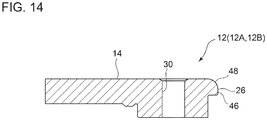
- connection portion 48 between a surface 40 of the first annular member 12 (12A, 12B) facing the second annular member 14 and an inner peripheral surface 46 of the first annular member 12 may have an R shape in the angular range D (see FIG. 15 ) in which the recess portions 28 do not exist in the circumferential direction of the turbine rotor 2.
- a recess portion 28 is formed on each of the second inner edge portions 26b.
- the present invention is not limited to this embodiment, and the recess portions 28 may be formed only on particular second inner edge portions 26b of the plurality of second inner edge portions 26b.
- the inner peripheral edge 26 may have only one recess portion 28.
- first annular member 12 (12A, 12B) only one recess portion 28 is formed on each of the second inner edge portions 26b. That is, the number of the second inner edge portions (number of support holes 30) is equal to the number of the recess portions 28.
- the present invention is not limited to this, and the number of the recess portions 28 formed on each of the second inner edge portions 26b may be two as shown in FIGs. 17A and 17B for instance, or three or more.
- each of the recess portions 28 having an arc shape is formed to penetrate through the first annular member 12 (12A) in the axial direction of the turbine rotor 2.
- each of the recess portions 28 having an arc shape may not necessarily penetrate through the first annular member 12 in the axial direction of the turbine rotor 2.
- each of the recess portions 28 is formed over the range of not less than 60% of the thickness of the annular protruding portion 42 in the axial direction of the turbine rotor 2.
- each of the recess portions 28 having a linear shape is formed not to penetrate through the first annular member 12 (12A) in the axial direction of the turbine rotor 2.
- each of the recess portions 28 having a linear shape may penetrate through the first annular member 12 (12B) in the axial direction of the turbine rotor 2.
- the first annular member 12 may have a configuration like that of the first annular member 12 (12E) shown in FIG. 18 , for instance.
- the inner peripheral edge 26 includes recess portions 28 curved so as to be recessed outward in the radial direction of the turbine rotor 2, and protruding portions 44 connecting smoothly to the recess portions 28 and curved so as to protrude inward in the radial direction of the turbine rotor 2.
- the recess portions 28 and the protruding portions 44 are formed alternately.
- one recess portion 28 is formed on each of the plurality of second inner edge portions 26b.
- the recess portions 28 curved so as to be recessed outward in the radial direction and the protruding portions 44 curved so as to protrude inward in the radial direction are connected smoothly, the connection between the recess portions 28 and parts other than the recess portions 28 is not structurally weak, but has a high durability.
- the first annular member 12 (12E) having such a shape can be easily produced by casting, for instance.
Landscapes
- Engineering & Computer Science (AREA)
- Mechanical Engineering (AREA)
- General Engineering & Computer Science (AREA)
- Chemical & Material Sciences (AREA)
- Combustion & Propulsion (AREA)
- Supercharger (AREA)
- Control Of Turbines (AREA)
Applications Claiming Priority (1)
| Application Number | Priority Date | Filing Date | Title |
|---|---|---|---|
| PCT/JP2015/086421 WO2017109995A1 (ja) | 2015-12-25 | 2015-12-25 | 可変ノズル機構および可変容量型ターボチャージャ |
Publications (3)
| Publication Number | Publication Date |
|---|---|
| EP3287619A1 true EP3287619A1 (de) | 2018-02-28 |
| EP3287619A4 EP3287619A4 (de) | 2018-05-09 |
| EP3287619B1 EP3287619B1 (de) | 2019-07-03 |
Family
ID=59089917
Family Applications (1)
| Application Number | Title | Priority Date | Filing Date |
|---|---|---|---|
| EP15911429.7A Active EP3287619B1 (de) | 2015-12-25 | 2015-12-25 | Variabler düsenmechanismus und turbolader mit variabler geometrie |
Country Status (5)
| Country | Link |
|---|---|
| US (1) | US10539069B2 (de) |
| EP (1) | EP3287619B1 (de) |
| JP (1) | JP6368057B2 (de) |
| CN (1) | CN107614847B (de) |
| WO (1) | WO2017109995A1 (de) |
Families Citing this family (7)
| Publication number | Priority date | Publication date | Assignee | Title |
|---|---|---|---|---|
| EP3628477B1 (de) | 2018-09-28 | 2021-03-31 | Siemens Gamesa Renewable Energy A/S | Verfahren zur reparatur eines fusses eines rotorblattes einer windturbine |
| CN114729596B (zh) | 2019-12-26 | 2023-10-13 | 三菱重工发动机和增压器株式会社 | 可变容量型涡轮增压器 |
| DE112020005428B4 (de) * | 2020-02-17 | 2025-12-04 | Mitsubishi Heavy Industries Engine & Turbocharger, Ltd. | Variable Düsenvorrichtung, Turbine und Turbolader |
| JP7444799B2 (ja) * | 2021-01-21 | 2024-03-06 | 三菱重工エンジン&ターボチャージャ株式会社 | 可変容量タービンおよび過給機 |
| CN119053772A (zh) * | 2022-05-25 | 2024-11-29 | 株式会社Ihi | 涡轮机以及增压器 |
| US20250347228A1 (en) * | 2022-07-06 | 2025-11-13 | Mitsubishi Heavy Industries Engine & Turbocharger, Ltd. | Turbine and turbocharger |
| CN120712400A (zh) * | 2023-03-31 | 2025-09-26 | 三菱重工发动机和增压器株式会社 | 可变喷嘴装置及可变容量型排气涡轮增压器 |
Family Cites Families (10)
| Publication number | Priority date | Publication date | Assignee | Title |
|---|---|---|---|---|
| US7771160B2 (en) * | 2006-08-10 | 2010-08-10 | United Technologies Corporation | Ceramic shroud assembly |
| US7559199B2 (en) * | 2006-09-22 | 2009-07-14 | Honeywell International Inc. | Variable-nozzle cartridge for a turbocharger |
| JP4807271B2 (ja) * | 2007-01-30 | 2011-11-02 | 株式会社Ihi | 可変容量型過給機 |
| JP4875602B2 (ja) | 2007-12-14 | 2012-02-15 | 三菱重工業株式会社 | 可変ノズル機構 |
| US8915704B2 (en) * | 2011-06-15 | 2014-12-23 | Honeywell International Inc. | Turbocharger variable-nozzle assembly with vane sealing ring |
| JP2013104412A (ja) * | 2011-11-16 | 2013-05-30 | Toyota Motor Corp | 可変ノズル機構 |
| JP6110741B2 (ja) * | 2013-06-27 | 2017-04-05 | 大同特殊鋼株式会社 | 摺動部材付きのユニソンリング及び摺動部材付きのユニソンリングの製造方法 |
| CN203547921U (zh) * | 2013-08-05 | 2014-04-16 | 天津机辆轨道交通装备有限责任公司 | 适用于焦炉煤气内燃机用燃机涡轮增压器 |
| JP6255786B2 (ja) | 2013-08-07 | 2018-01-10 | 株式会社Ihi | 可変容量型過給機 |
| JP5991296B2 (ja) * | 2013-09-25 | 2016-09-14 | トヨタ自動車株式会社 | 排気ターボチャージャ |
-
2015
- 2015-12-25 CN CN201580080192.4A patent/CN107614847B/zh active Active
- 2015-12-25 EP EP15911429.7A patent/EP3287619B1/de active Active
- 2015-12-25 WO PCT/JP2015/086421 patent/WO2017109995A1/ja not_active Ceased
- 2015-12-25 US US15/576,951 patent/US10539069B2/en active Active
- 2015-12-25 JP JP2017557664A patent/JP6368057B2/ja not_active Expired - Fee Related
Also Published As
| Publication number | Publication date |
|---|---|
| CN107614847A (zh) | 2018-01-19 |
| US20180149078A1 (en) | 2018-05-31 |
| CN107614847B (zh) | 2019-11-19 |
| EP3287619A4 (de) | 2018-05-09 |
| JP6368057B2 (ja) | 2018-08-01 |
| EP3287619B1 (de) | 2019-07-03 |
| WO2017109995A1 (ja) | 2017-06-29 |
| JPWO2017109995A1 (ja) | 2018-02-15 |
| US10539069B2 (en) | 2020-01-21 |
Similar Documents
| Publication | Publication Date | Title |
|---|---|---|
| EP3287619B1 (de) | Variabler düsenmechanismus und turbolader mit variabler geometrie | |
| KR101994511B1 (ko) | 노즐 링 | |
| US9347460B2 (en) | Rotary machine | |
| EP2998508B1 (de) | Verstellbare leitschaufeln und verfahren zur minimierung von endwandleckagen | |
| CN106536867B (zh) | 静叶、燃气轮机、分割环、静叶的改造方法以及分割环的改造方法 | |
| JP2016108956A (ja) | コンプレッサ、これを備えた過給機、ならびにコンプレッサのスロート通路幅調整方法 | |
| EP3141698A1 (de) | Anordnung für eine gasturbine | |
| US10287989B2 (en) | Seal support of titanium aluminide for a turbomachine | |
| CA2941356A1 (en) | Ceramic matrix composite ring shroud retention methods-wiggle strip spring seal | |
| EP2904241B1 (de) | Fehlhandlungssichere brennkammerdichtung für einen gasturbinenmotor | |
| JP2013002466A (ja) | スラスト軸受構造及び過給機 | |
| US10267171B2 (en) | Seal assembly for a turbomachine | |
| EP2803821A1 (de) | Schaufelvorrichtung, Schaufelsystem und zugehöriges Herstellungsverfahren eines Schaufelsystems | |
| US10443605B2 (en) | Impeller, rotary machine, and impeller manufacturing method | |
| US9951654B2 (en) | Stator blade sector for an axial turbomachine with a dual means of fixing | |
| US9644491B2 (en) | Single bolting flange arrangement for variable guide vane connection | |
| EP3173599B1 (de) | Mechanismus für variable düse und turbolader mit variabler verdrängung | |
| JPWO2018147162A1 (ja) | 軸流機械の翼 | |
| US10443417B2 (en) | Ceramic matrix composite ring shroud retention methods-finger seals with stepped shroud interface | |
| US11339680B2 (en) | Radial inflow turbine and turbocharger | |
| US11092068B2 (en) | Variable geometry turbocharger | |
| US10047621B2 (en) | Sealing plate with fuse function | |
| US20200200033A1 (en) | Turbo machine |
Legal Events
| Date | Code | Title | Description |
|---|---|---|---|
| STAA | Information on the status of an ep patent application or granted ep patent |
Free format text: STATUS: THE INTERNATIONAL PUBLICATION HAS BEEN MADE |
|
| PUAI | Public reference made under article 153(3) epc to a published international application that has entered the european phase |
Free format text: ORIGINAL CODE: 0009012 |
|
| STAA | Information on the status of an ep patent application or granted ep patent |
Free format text: STATUS: REQUEST FOR EXAMINATION WAS MADE |
|
| 17P | Request for examination filed |
Effective date: 20171123 |
|
| AK | Designated contracting states |
Kind code of ref document: A1 Designated state(s): AL AT BE BG CH CY CZ DE DK EE ES FI FR GB GR HR HU IE IS IT LI LT LU LV MC MK MT NL NO PL PT RO RS SE SI SK SM TR |
|
| AX | Request for extension of the european patent |
Extension state: BA ME |
|
| A4 | Supplementary search report drawn up and despatched |
Effective date: 20180410 |
|
| RIC1 | Information provided on ipc code assigned before grant |
Ipc: F01D 17/16 20060101ALI20180404BHEP Ipc: F02B 37/24 20060101AFI20180404BHEP |
|
| RAP1 | Party data changed (applicant data changed or rights of an application transferred) |
Owner name: MITSUBISHI HEAVY INDUSTRIES ENGINE & TURBOCHARGER, |
|
| GRAP | Despatch of communication of intention to grant a patent |
Free format text: ORIGINAL CODE: EPIDOSNIGR1 |
|
| STAA | Information on the status of an ep patent application or granted ep patent |
Free format text: STATUS: GRANT OF PATENT IS INTENDED |
|
| INTG | Intention to grant announced |
Effective date: 20190204 |
|
| DAV | Request for validation of the european patent (deleted) | ||
| DAX | Request for extension of the european patent (deleted) | ||
| GRAS | Grant fee paid |
Free format text: ORIGINAL CODE: EPIDOSNIGR3 |
|
| GRAA | (expected) grant |
Free format text: ORIGINAL CODE: 0009210 |
|
| STAA | Information on the status of an ep patent application or granted ep patent |
Free format text: STATUS: THE PATENT HAS BEEN GRANTED |
|
| AK | Designated contracting states |
Kind code of ref document: B1 Designated state(s): AL AT BE BG CH CY CZ DE DK EE ES FI FR GB GR HR HU IE IS IT LI LT LU LV MC MK MT NL NO PL PT RO RS SE SI SK SM TR |
|
| REG | Reference to a national code |
Ref country code: GB Ref legal event code: FG4D |
|
| REG | Reference to a national code |
Ref country code: CH Ref legal event code: EP Ref country code: AT Ref legal event code: REF Ref document number: 1151275 Country of ref document: AT Kind code of ref document: T Effective date: 20190715 |
|
| REG | Reference to a national code |
Ref country code: IE Ref legal event code: FG4D |
|
| REG | Reference to a national code |
Ref country code: DE Ref legal event code: R096 Ref document number: 602015033369 Country of ref document: DE |
|
| REG | Reference to a national code |
Ref country code: NL Ref legal event code: MP Effective date: 20190703 |
|
| REG | Reference to a national code |
Ref country code: LT Ref legal event code: MG4D |
|
| REG | Reference to a national code |
Ref country code: AT Ref legal event code: MK05 Ref document number: 1151275 Country of ref document: AT Kind code of ref document: T Effective date: 20190703 |
|
| PG25 | Lapsed in a contracting state [announced via postgrant information from national office to epo] |
Ref country code: PT Free format text: LAPSE BECAUSE OF FAILURE TO SUBMIT A TRANSLATION OF THE DESCRIPTION OR TO PAY THE FEE WITHIN THE PRESCRIBED TIME-LIMIT Effective date: 20191104 Ref country code: AT Free format text: LAPSE BECAUSE OF FAILURE TO SUBMIT A TRANSLATION OF THE DESCRIPTION OR TO PAY THE FEE WITHIN THE PRESCRIBED TIME-LIMIT Effective date: 20190703 Ref country code: HR Free format text: LAPSE BECAUSE OF FAILURE TO SUBMIT A TRANSLATION OF THE DESCRIPTION OR TO PAY THE FEE WITHIN THE PRESCRIBED TIME-LIMIT Effective date: 20190703 Ref country code: LT Free format text: LAPSE BECAUSE OF FAILURE TO SUBMIT A TRANSLATION OF THE DESCRIPTION OR TO PAY THE FEE WITHIN THE PRESCRIBED TIME-LIMIT Effective date: 20190703 Ref country code: SE Free format text: LAPSE BECAUSE OF FAILURE TO SUBMIT A TRANSLATION OF THE DESCRIPTION OR TO PAY THE FEE WITHIN THE PRESCRIBED TIME-LIMIT Effective date: 20190703 Ref country code: NL Free format text: LAPSE BECAUSE OF FAILURE TO SUBMIT A TRANSLATION OF THE DESCRIPTION OR TO PAY THE FEE WITHIN THE PRESCRIBED TIME-LIMIT Effective date: 20190703 Ref country code: BG Free format text: LAPSE BECAUSE OF FAILURE TO SUBMIT A TRANSLATION OF THE DESCRIPTION OR TO PAY THE FEE WITHIN THE PRESCRIBED TIME-LIMIT Effective date: 20191003 Ref country code: FI Free format text: LAPSE BECAUSE OF FAILURE TO SUBMIT A TRANSLATION OF THE DESCRIPTION OR TO PAY THE FEE WITHIN THE PRESCRIBED TIME-LIMIT Effective date: 20190703 Ref country code: NO Free format text: LAPSE BECAUSE OF FAILURE TO SUBMIT A TRANSLATION OF THE DESCRIPTION OR TO PAY THE FEE WITHIN THE PRESCRIBED TIME-LIMIT Effective date: 20191003 Ref country code: CZ Free format text: LAPSE BECAUSE OF FAILURE TO SUBMIT A TRANSLATION OF THE DESCRIPTION OR TO PAY THE FEE WITHIN THE PRESCRIBED TIME-LIMIT Effective date: 20190703 |
|
| PG25 | Lapsed in a contracting state [announced via postgrant information from national office to epo] |
Ref country code: RS Free format text: LAPSE BECAUSE OF FAILURE TO SUBMIT A TRANSLATION OF THE DESCRIPTION OR TO PAY THE FEE WITHIN THE PRESCRIBED TIME-LIMIT Effective date: 20190703 Ref country code: LV Free format text: LAPSE BECAUSE OF FAILURE TO SUBMIT A TRANSLATION OF THE DESCRIPTION OR TO PAY THE FEE WITHIN THE PRESCRIBED TIME-LIMIT Effective date: 20190703 Ref country code: IS Free format text: LAPSE BECAUSE OF FAILURE TO SUBMIT A TRANSLATION OF THE DESCRIPTION OR TO PAY THE FEE WITHIN THE PRESCRIBED TIME-LIMIT Effective date: 20191103 Ref country code: AL Free format text: LAPSE BECAUSE OF FAILURE TO SUBMIT A TRANSLATION OF THE DESCRIPTION OR TO PAY THE FEE WITHIN THE PRESCRIBED TIME-LIMIT Effective date: 20190703 Ref country code: GR Free format text: LAPSE BECAUSE OF FAILURE TO SUBMIT A TRANSLATION OF THE DESCRIPTION OR TO PAY THE FEE WITHIN THE PRESCRIBED TIME-LIMIT Effective date: 20191004 Ref country code: ES Free format text: LAPSE BECAUSE OF FAILURE TO SUBMIT A TRANSLATION OF THE DESCRIPTION OR TO PAY THE FEE WITHIN THE PRESCRIBED TIME-LIMIT Effective date: 20190703 |
|
| PG25 | Lapsed in a contracting state [announced via postgrant information from national office to epo] |
Ref country code: TR Free format text: LAPSE BECAUSE OF FAILURE TO SUBMIT A TRANSLATION OF THE DESCRIPTION OR TO PAY THE FEE WITHIN THE PRESCRIBED TIME-LIMIT Effective date: 20190703 |
|
| PG25 | Lapsed in a contracting state [announced via postgrant information from national office to epo] |
Ref country code: DK Free format text: LAPSE BECAUSE OF FAILURE TO SUBMIT A TRANSLATION OF THE DESCRIPTION OR TO PAY THE FEE WITHIN THE PRESCRIBED TIME-LIMIT Effective date: 20190703 Ref country code: PL Free format text: LAPSE BECAUSE OF FAILURE TO SUBMIT A TRANSLATION OF THE DESCRIPTION OR TO PAY THE FEE WITHIN THE PRESCRIBED TIME-LIMIT Effective date: 20190703 Ref country code: RO Free format text: LAPSE BECAUSE OF FAILURE TO SUBMIT A TRANSLATION OF THE DESCRIPTION OR TO PAY THE FEE WITHIN THE PRESCRIBED TIME-LIMIT Effective date: 20190703 Ref country code: IT Free format text: LAPSE BECAUSE OF FAILURE TO SUBMIT A TRANSLATION OF THE DESCRIPTION OR TO PAY THE FEE WITHIN THE PRESCRIBED TIME-LIMIT Effective date: 20190703 Ref country code: EE Free format text: LAPSE BECAUSE OF FAILURE TO SUBMIT A TRANSLATION OF THE DESCRIPTION OR TO PAY THE FEE WITHIN THE PRESCRIBED TIME-LIMIT Effective date: 20190703 |
|
| PG25 | Lapsed in a contracting state [announced via postgrant information from national office to epo] |
Ref country code: SM Free format text: LAPSE BECAUSE OF FAILURE TO SUBMIT A TRANSLATION OF THE DESCRIPTION OR TO PAY THE FEE WITHIN THE PRESCRIBED TIME-LIMIT Effective date: 20190703 Ref country code: IS Free format text: LAPSE BECAUSE OF FAILURE TO SUBMIT A TRANSLATION OF THE DESCRIPTION OR TO PAY THE FEE WITHIN THE PRESCRIBED TIME-LIMIT Effective date: 20200224 Ref country code: SK Free format text: LAPSE BECAUSE OF FAILURE TO SUBMIT A TRANSLATION OF THE DESCRIPTION OR TO PAY THE FEE WITHIN THE PRESCRIBED TIME-LIMIT Effective date: 20190703 |
|
| REG | Reference to a national code |
Ref country code: DE Ref legal event code: R097 Ref document number: 602015033369 Country of ref document: DE |
|
| PLBE | No opposition filed within time limit |
Free format text: ORIGINAL CODE: 0009261 |
|
| STAA | Information on the status of an ep patent application or granted ep patent |
Free format text: STATUS: NO OPPOSITION FILED WITHIN TIME LIMIT |
|
| PG2D | Information on lapse in contracting state deleted |
Ref country code: IS |
|
| REG | Reference to a national code |
Ref country code: CH Ref legal event code: PL |
|
| 26N | No opposition filed |
Effective date: 20200603 |
|
| REG | Reference to a national code |
Ref country code: BE Ref legal event code: MM Effective date: 20191231 |
|
| PG25 | Lapsed in a contracting state [announced via postgrant information from national office to epo] |
Ref country code: MC Free format text: LAPSE BECAUSE OF FAILURE TO SUBMIT A TRANSLATION OF THE DESCRIPTION OR TO PAY THE FEE WITHIN THE PRESCRIBED TIME-LIMIT Effective date: 20190703 Ref country code: SI Free format text: LAPSE BECAUSE OF FAILURE TO SUBMIT A TRANSLATION OF THE DESCRIPTION OR TO PAY THE FEE WITHIN THE PRESCRIBED TIME-LIMIT Effective date: 20190703 |
|
| GBPC | Gb: european patent ceased through non-payment of renewal fee |
Effective date: 20191225 |
|
| PG25 | Lapsed in a contracting state [announced via postgrant information from national office to epo] |
Ref country code: FR Free format text: LAPSE BECAUSE OF NON-PAYMENT OF DUE FEES Effective date: 20191231 Ref country code: IE Free format text: LAPSE BECAUSE OF NON-PAYMENT OF DUE FEES Effective date: 20191225 Ref country code: GB Free format text: LAPSE BECAUSE OF NON-PAYMENT OF DUE FEES Effective date: 20191225 Ref country code: LU Free format text: LAPSE BECAUSE OF NON-PAYMENT OF DUE FEES Effective date: 20191225 |
|
| PG25 | Lapsed in a contracting state [announced via postgrant information from national office to epo] |
Ref country code: LI Free format text: LAPSE BECAUSE OF NON-PAYMENT OF DUE FEES Effective date: 20191231 Ref country code: CH Free format text: LAPSE BECAUSE OF NON-PAYMENT OF DUE FEES Effective date: 20191231 Ref country code: BE Free format text: LAPSE BECAUSE OF NON-PAYMENT OF DUE FEES Effective date: 20191231 |
|
| PG25 | Lapsed in a contracting state [announced via postgrant information from national office to epo] |
Ref country code: CY Free format text: LAPSE BECAUSE OF FAILURE TO SUBMIT A TRANSLATION OF THE DESCRIPTION OR TO PAY THE FEE WITHIN THE PRESCRIBED TIME-LIMIT Effective date: 20190703 |
|
| PG25 | Lapsed in a contracting state [announced via postgrant information from national office to epo] |
Ref country code: HU Free format text: LAPSE BECAUSE OF FAILURE TO SUBMIT A TRANSLATION OF THE DESCRIPTION OR TO PAY THE FEE WITHIN THE PRESCRIBED TIME-LIMIT; INVALID AB INITIO Effective date: 20151225 Ref country code: MT Free format text: LAPSE BECAUSE OF FAILURE TO SUBMIT A TRANSLATION OF THE DESCRIPTION OR TO PAY THE FEE WITHIN THE PRESCRIBED TIME-LIMIT Effective date: 20190703 |
|
| PG25 | Lapsed in a contracting state [announced via postgrant information from national office to epo] |
Ref country code: MK Free format text: LAPSE BECAUSE OF FAILURE TO SUBMIT A TRANSLATION OF THE DESCRIPTION OR TO PAY THE FEE WITHIN THE PRESCRIBED TIME-LIMIT Effective date: 20190703 |
|
| PGFP | Annual fee paid to national office [announced via postgrant information from national office to epo] |
Ref country code: DE Payment date: 20241029 Year of fee payment: 10 |