EP3287681B1 - Rechtwinkliges ventil - Google Patents
Rechtwinkliges ventil Download PDFInfo
- Publication number
- EP3287681B1 EP3287681B1 EP16186011.9A EP16186011A EP3287681B1 EP 3287681 B1 EP3287681 B1 EP 3287681B1 EP 16186011 A EP16186011 A EP 16186011A EP 3287681 B1 EP3287681 B1 EP 3287681B1
- Authority
- EP
- European Patent Office
- Prior art keywords
- pipe
- right angle
- cover
- piston
- disc spring
- Prior art date
- Legal status (The legal status is an assumption and is not a legal conclusion. Google has not performed a legal analysis and makes no representation as to the accuracy of the status listed.)
- Active
Links
Images



Classifications
-
- F—MECHANICAL ENGINEERING; LIGHTING; HEATING; WEAPONS; BLASTING
- F16—ENGINEERING ELEMENTS AND UNITS; GENERAL MEASURES FOR PRODUCING AND MAINTAINING EFFECTIVE FUNCTIONING OF MACHINES OR INSTALLATIONS; THERMAL INSULATION IN GENERAL
- F16K—VALVES; TAPS; COCKS; ACTUATING-FLOATS; DEVICES FOR VENTING OR AERATING
- F16K49/00—Means in or on valves for heating or cooling
- F16K49/002—Electric heating means
-
- F—MECHANICAL ENGINEERING; LIGHTING; HEATING; WEAPONS; BLASTING
- F16—ENGINEERING ELEMENTS AND UNITS; GENERAL MEASURES FOR PRODUCING AND MAINTAINING EFFECTIVE FUNCTIONING OF MACHINES OR INSTALLATIONS; THERMAL INSULATION IN GENERAL
- F16K—VALVES; TAPS; COCKS; ACTUATING-FLOATS; DEVICES FOR VENTING OR AERATING
- F16K1/00—Lift valves or globe valves, i.e. cut-off apparatus with closure members having at least a component of their opening and closing motion perpendicular to the closing faces
- F16K1/32—Details
- F16K1/34—Cutting-off parts, e.g. valve members, seats
- F16K1/36—Valve members
-
- F—MECHANICAL ENGINEERING; LIGHTING; HEATING; WEAPONS; BLASTING
- F16—ENGINEERING ELEMENTS AND UNITS; GENERAL MEASURES FOR PRODUCING AND MAINTAINING EFFECTIVE FUNCTIONING OF MACHINES OR INSTALLATIONS; THERMAL INSULATION IN GENERAL
- F16K—VALVES; TAPS; COCKS; ACTUATING-FLOATS; DEVICES FOR VENTING OR AERATING
- F16K51/00—Other details not peculiar to particular types of valves or cut-off apparatus
- F16K51/02—Other details not peculiar to particular types of valves or cut-off apparatus specially adapted for high-vacuum installations
Definitions
- the present invention relates to right angle valves, and more particularly, to a right angle valve capable of covering the disc spring in order to prevent the disc spring from being stuck by other objects and facilitate the position recovering operation thereof.
- the known right angle valve is used to adjusting or block the air flowing in a vacuum system.
- the known right angle valve often includes a three way pipe 1, a piston 2, a controlling shaft 3, and a valve plate 4.
- the piston 2 is movably disposed on one end of the three way pipe 1.
- One end of the controlling shaft 3 is connected to the piston 2, with the other end thereof connected to the valve plate 4 for controlling the valve plate 4 to open or close the three way pipe 1.
- a disc spring 5 is disposed between the valve plate 4 and the controlling shaft 3, so as to provide a position recovering force to the piston 2.
- the piston 2 When the piston 2 is driven due to an air pressure, the piston 2 forces the controlling shaft 3 to move, thereby triggering the valve plate 4 to allow the connection in the three way pipe 1; at the meantime, the disc spring 5 is compressed. When the air pressure is removed, with the resilient force provided by the disc spring 5, the piston 2 moves to make the valve plate 4 block the connection in the three way pipe 1. With such operation, the air inflow and outflow are achieved. However, during the air inflow and outflow, the air might contain a certain amount of impurities, foreign matter, or dust, such objects are easily stuck on or attached to the disc spring 5. As a result, the movement of the disc spring 5 is kept from being facilitate, failing to accomplish a compete position recovering operation.
- a right angle valve provided with a flexible bellows is disclosed in US2008/173842 , US2012/126159 , EP0780615 and WO2009/126578 , respectively.
- the disc spring is covered in the bellows and not being exposed.
- the present invention discloses a right angle valve, which applies a covering measure to cover the disc spring when the air inflow is permitted, so as to prevent the disc spring from being stuck by foreign objects and facilitate the operation thereof, in accordance to claim 1.
- a right angle valve comprising:
- the covering measure includes a sleeve provided with a fixing end and a free end.
- the fixing end is fixedly combined with the fixing member, and the free end surrounds the combining end of fixing member and the disc spring.
- the covering measure includes a sleeve that is fixedly combined with the sealing member and surrounds the disc spring.
- the cover is provided with an inner space
- the piston member has a piston body slidingly disposed in the inner space.
- an air inflow portion is disposed at the cover adjacent to the valve body, and the air inflow portion is connected with the inner space.
- the piston body is connected with a controlling shaft.
- the controlling shaft passes through the fixing member and is connected with the sealing member.
- the piston body is concavely provided with a spring recess; the cover is provided with a sealed end; a spring is disposed between the spring recess and the sealed end.
- a positioning member is inserted in the spring.
- the sealed end of the cover is provided with a silencing member, wherein the inner end of the silencing member contacts the inner space.
- a heating device is further provided for heating the valve body.
- a heat insulating plate is further provided and disposed between the valve body and the cover.
- the heating device is used to heat the valve body, such that when the first pipe is opened, the micro-size foreign matters or objects are burned by the high temperature heat. Therefore, the foreign objects are unable to be accumulated in the pipe.
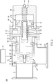
- the right angle valve 100 provided by an embodiment of the present invention comprises a valve body 10, a fixing member 20, a disc spring 30, a cover 40, and a piston member 50.
- the valve body 10 is a three way pipe, comprising a cavity 11 and a first pipe 12 and a second pipe 13 that are connected with the cavity 11.
- the first pipe 12 and the cavity 11 are arranged in an axial alignment.
- the first pipe 12 and the second pipe 13 form a right angle arrangement.
- the fixing member 20 is formed in a barrel shape structure and fixed on one end of the valve body 10 away from the first pipe 12.
- the fixing member 20 is provided with a combining end 21 inserted into the cavity 11.
- the disc spring 30 has one end thereof combined with a combining end 21 of the fixing member 20, while the other end thereof is connected with a sealing member 31 for sealing the inner end of the first pipe 12, so as to optionally open or close to allow or block the connection between the first pipe 12 and the cavity 11.
- the cover 40 is fixed on one end of the valve body 10 away from the first pipe 12 and arranged on the outer side of the fixing member 20.
- the cover 40 includes an inner space 41.
- An air inflow portion 42 is disposed on the cover 40 adjacent to the valve body 10.
- the air inflow portion 42 comprises an air inlet 421 which is connected with the inner space 41 for contacting an outer air source, such that the air is input into the inner space 41.
- one end of the cover 40 away from the air inflow portion 42 is provided with a sealed end 43.
- the sealed end 43 includes a silencing member 44, wherein the inner end of the silencing member 44 is connected with the inner space 41 for balancing the inner pressure and the outer pressure of the cover 40.
- the sealed end 43 of the cover 40 is provided with a positioning recess 45 which is connected with the inner space 41 and the inner end of the silencing member 44.
- the piston member 50 is slidingly disposed inside the cover 40.
- the piston member 50 includes a piston body 51 which is slidingly disposed in the inner space 41.
- the piston body 51 is combined with a controlling shaft 52.
- the controlling shaft 52 pass through the air inflow portion 42 and the fixing member 20, wherein one end of the controlling shaft 52 is combined with the sealing member 31.
- the sealing member 31 optionally opens or closes the first pipe 12.
- the piston body 51 is axially and concavely provided with a spring recess 53 which receives a spring 54, such that the spring 54 is disposed between the spring recess 53 and the positioning recess 45 of the sealed end 43, thereby providing the recovering function of the piston member 50.
- a positioning member 55 is disposed in the spring recess 53, and the positioning member 55 is formed in a T shape, so as to be inserted into the spring 54 in order to position the spring 54.
- An embodiment of the present invention further comprises a covering measure.
- the covering measure includes a sleeve 60, which comprises a fixing end 61 and a free end 62.
- the sleeve 60 is mounted around the fixing member 20, such that the fixing end 61 is fastened with the fixing member 20 by use of screws or bolts, and the free end 62 surrounds the combining end 21 of the fixing member 20 and the disc spring 30.
- the outer diameter of the free end 62 of the sleeve 60 is substantially equal to the outer diameter of the sealing member 31.
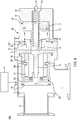
- an embodiment of the present invention includes a heating device 70, which heats the valve body 10 by in a contact or non-contact manner.
- a heating device 70 which heats the valve body 10 by in a contact or non-contact manner.
- a heat insulating plate 71 is disposed between the valve body 10 and the cover 40.
- the heating device 70 heats the valve body 10
- the heat is transmitted to the cover 40, so as to prevent the adverse effects due to the operation of the piston member 50 and the air leakage from happening.
- the piston member 50 moves to open the first pipe 12.
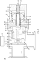
- Fig. 3 by inputting a high pressure air from the outside, when the piston member 50 pushes the piston body 51 to move toward the sealed end 43 of the cover 40, the piston body 51, by use of the controlling shaft 52, drives the sealing member 31 to gradually move away from the inner end of the first pipe 12, whereby the connection between the first pipe 12 and the second pipe 13 is established.
- the disc spring 30 bears a force to be compressed.
- Fig. 3 by inputting a high pressure air from the outside, when the piston member 50 pushes the piston body 51 to move toward the sealed end 43 of the cover 40, the piston body 51, by use of the controlling shaft 52, drives the sealing member 31 to gradually move away from the inner end of the first pipe 12, whereby the connection between the first pipe 12 and the second pipe 13 is established.
- the disc spring 30 bears a force to be compressed.
- the covering measure includes a sleeve 80 which is fixedly combined with the sealing member 31 and surrounds the disc spring 30.
- the sleeve 80 is allowed to be integrally formed with the sealing member 31.
- the combining end 21 of the fixing member 20 is provided with a held portion 22.
- the disc spring 30 is covered in the sleeve 60 or sleeve 80, such that the disc spring 30 is prevented from being stuck or attached by foreign objects in the flowing air, assuring the normal operation of the disc spring 30.
- the heating device 70 heating the valve body 10, when the first pipe 12 is opened, the foreign matters or objects in the valve body 10 are burned by the high temperature heat, preventing the foreign objects from sticking or accumulating in the pipe.
Landscapes
- Engineering & Computer Science (AREA)
- General Engineering & Computer Science (AREA)
- Mechanical Engineering (AREA)
- Details Of Valves (AREA)
Claims (9)
- Rechtwinkliges Ventil (100), welches umfasst:einen Ventilkörper (10), der einen Hohlraum (11) und ein erstes Rohr (12) und ein zweites Rohr (13) umfasst, die mit dem Hohlraum (11) verbunden sind;ein Befestigungselement (20), das mit dem Ventilkörper (10) befestigt ist, worin das Befestigungselement (20) mit einem in den Hohlraum (11) eingesetzten Verbindungsende (21) versehen ist;eine Tellerfeder (30), die mit einem Ende mit dem Verbindungsende (21) verbunden und dem anderen Ende zum Abdichten eines inneren Endes des ersten Rohres (12) mit einem Dichtungsteil (31) verbunden ist;eine Abdeckung (40), die an einem Ende des Ventilkörpers (10) von dem ersten Rohr (12) weg befestigt ist;ein Kolbenelement (50), das in der Abdeckung (40) gleitend angeordnet ist, worin ein Ende des Kolbenelements (50) mit dem Dichtungsteil (31) verbunden ist; undein Abdeckungsmittel, das eine Hülse (60) umfasst, worin das Abdeckungsmittel die Tellerfeder (30) bedeckt, wenn das Kolbenelement (50) das Dichtungsteil (31) antreibt, sich von dem inneren Ende des ersten Rohres (12) weg zu bewegen, um einen Lufteinstrom derart zu ermöglichen, dass verhindert wird, dass die Tellerfeder (30) der strömenden Luft ausgesetzt wird,
dadurch gekennzeichnet, dassdie Hülse (60) ein Befestigungsende (61) und ein freies Ende (62) umfasst, das Befestigungsende (61) mit dem Befestigungselement fest verbunden ist, das freie Ende (62) das Verbindungsende (21) des Befestigungselements (20) und die Tellerfeder (30) umgibt, worin das Dichtungsteil (31) gegen das freie Ende (62) aufliegt, wenn sich das Dichtungsteil (31) von dem inneren Ende des ersten Rohres (12) zu der größten Entfernung weg bewegt. - Rechtwinkliges Ventil (100) nach Anspruch 1, worin das Befestigungsende (61) mit dem Befestigungselement (20) befestigt ist.
- Rechtwinkliges Ventil (100) nach Anspruch 1, worin die Abdeckung (40) mit einem inneren Raum (41) versehen ist, worin das Kolbenelement (50) einen gleitend in dem inneren Raum (41) angeordneten Kolbenkörper (51) umfasst, und worin ein mit dem inneren Raum (41) verbundener Lufteinstrombereich (42) an der Abdeckung (40) benachbart zu dem Ventilkörper (10) angeordnet ist.
- Rechtwinkliges Ventil (100) nach Anspruch 3, worin der Kolbenkörper (51) mit einem Steuerschaft (52) verbunden ist, worin der Steuerschaft (52) durch das Befestigungselement (20) geht und mit dem Dichtungsteil (31) verbunden ist.
- Rechtwinkliges Ventil (100) nach Anspruch 3, worin der Kolbenkörper (51) mit einer Federaussparung (53) ausgehöhlt vorgesehen ist, die Abdeckung (40) mit einem dichten Ende (43) versehen ist, und eine Feder (54) zwischen der Federaussparung (53) und dem dichten Ende (43) angeordnet ist.
- Rechtwinkliges Ventil (100) nach Anspruch 5, worin ein Anordnungselement (55) in der Federaussparung (53) angeordnet ist, um in die Feder (54) eingesetzt zu werden.
- Rechtwinkliges Ventil (100) nach Anspruch 5, worin das dichte Ende (43) der Abdeckung (40) mit einem Schalldämpfungselement (44) versehen ist, worin ein inneres Ende des Schalldämpfungselementes (44) mit dem inneren Raum (41) in Kontakt steht.
- Rechtwinkliges Ventil (100) nach Anspruch 1, welches weiter eine Heizeinrichtung (70) zum Heizen des Ventilkörpers (10) umfasst.
- Rechtwinkliges Ventil (100) nach Anspruch 8, welches weiter eine Wärmeisolationsplatte (71) umfasst, die zwischen dem Ventilkörper (10) und der Abdeckung (40) angeordnet ist.
Priority Applications (1)
| Application Number | Priority Date | Filing Date | Title |
|---|---|---|---|
| EP16186011.9A EP3287681B1 (de) | 2016-08-26 | 2016-08-26 | Rechtwinkliges ventil |
Applications Claiming Priority (1)
| Application Number | Priority Date | Filing Date | Title |
|---|---|---|---|
| EP16186011.9A EP3287681B1 (de) | 2016-08-26 | 2016-08-26 | Rechtwinkliges ventil |
Publications (2)
| Publication Number | Publication Date |
|---|---|
| EP3287681A1 EP3287681A1 (de) | 2018-02-28 |
| EP3287681B1 true EP3287681B1 (de) | 2020-02-19 |
Family
ID=56852098
Family Applications (1)
| Application Number | Title | Priority Date | Filing Date |
|---|---|---|---|
| EP16186011.9A Active EP3287681B1 (de) | 2016-08-26 | 2016-08-26 | Rechtwinkliges ventil |
Country Status (1)
| Country | Link |
|---|---|
| EP (1) | EP3287681B1 (de) |
Families Citing this family (3)
| Publication number | Priority date | Publication date | Assignee | Title |
|---|---|---|---|---|
| FR3103530B1 (fr) * | 2019-11-26 | 2021-11-05 | Asco Sas | Vanne cryogénique avec réduction du transfert thermique |
| DE102021102284A1 (de) * | 2021-02-01 | 2022-08-04 | Vat Holding Ag | Ventilplatte für eine Verschlusseinrichtung zum vakuumdichten Verschließen einer Öffnung in einer Wand |
| DE102021102283A1 (de) * | 2021-02-01 | 2022-08-04 | Vat Holding Ag | Verschlussvorrichtung zum vakuumdichten Verschließen einer Öffnung in einer Wand |
Family Cites Families (5)
| Publication number | Priority date | Publication date | Assignee | Title |
|---|---|---|---|---|
| US5678595A (en) * | 1995-12-21 | 1997-10-21 | Benkan Corporation | Vacuum exhaust valve |
| JP3778866B2 (ja) * | 2002-03-20 | 2006-05-24 | Smc株式会社 | ヒーター付き真空バルブ |
| JP5066724B2 (ja) * | 2007-01-17 | 2012-11-07 | Smc株式会社 | 高真空バルブ |
| US8196893B2 (en) * | 2008-04-09 | 2012-06-12 | Mks Instruments, Inc. | Isolation valve with corrosion protected and heat transfer enhanced valve actuator and closure apparatus and method |
| KR101013137B1 (ko) * | 2010-11-19 | 2011-02-10 | 이동민 | 진공 공정용 밸브 |
-
2016
- 2016-08-26 EP EP16186011.9A patent/EP3287681B1/de active Active
Non-Patent Citations (1)
| Title |
|---|
| None * |
Also Published As
| Publication number | Publication date |
|---|---|
| EP3287681A1 (de) | 2018-02-28 |
Similar Documents
| Publication | Publication Date | Title |
|---|---|---|
| US9395006B2 (en) | Check valve | |
| JP5435439B2 (ja) | 二方弁 | |
| EP3287681B1 (de) | Rechtwinkliges ventil | |
| KR20180029714A (ko) | 직각 밸브 | |
| EP3108167B1 (de) | Aktuator mit integriertem jochrohr | |
| US20180051820A1 (en) | Right angle valve | |
| CN112628455B (zh) | 用于动力阀的膜 | |
| WO2017156831A1 (zh) | 燃气比例阀 | |
| US20150300508A1 (en) | Valve Seat for Floating Ball Valve | |
| RU2614651C2 (ru) | Термостатический клапан, в частности радиаторный клапан | |
| JP2012233579A (ja) | バルブ | |
| JP6002933B2 (ja) | 逆止弁およびそれを備えた給湯機 | |
| JP2018534499A (ja) | 圧力制限弁 | |
| JPWO2019026814A1 (ja) | バルブ | |
| WO2017085130A3 (de) | Kupplungsmuffe für eine hydraulikkupplung | |
| JP6257717B1 (ja) | 直角弁 | |
| JP6021702B2 (ja) | 漏洩防止シール、原子炉冷却材ポンプ | |
| WO2016015620A1 (zh) | 调节器的执行器及流体调节器 | |
| KR20160137204A (ko) | 형상기억합금을 이용한 체크밸브 | |
| US20150377371A1 (en) | Intelligent Pressure Relief Device For A Double Isolation Valve | |
| TWI792686B (zh) | 磁控流體遮斷器 | |
| JP6220273B2 (ja) | 逃し弁 | |
| CN105090574B (zh) | 一种适应于高温气体的压力感应开关 | |
| JP6033119B2 (ja) | 調節弁 | |
| RU2459128C1 (ru) | Затвор пневмоклапана |
Legal Events
| Date | Code | Title | Description |
|---|---|---|---|
| PUAI | Public reference made under article 153(3) epc to a published international application that has entered the european phase |
Free format text: ORIGINAL CODE: 0009012 |
|
| STAA | Information on the status of an ep patent application or granted ep patent |
Free format text: STATUS: THE APPLICATION HAS BEEN PUBLISHED |
|
| AK | Designated contracting states |
Kind code of ref document: A1 Designated state(s): AL AT BE BG CH CY CZ DE DK EE ES FI FR GB GR HR HU IE IS IT LI LT LU LV MC MK MT NL NO PL PT RO RS SE SI SK SM TR |
|
| AX | Request for extension of the european patent |
Extension state: BA ME |
|
| STAA | Information on the status of an ep patent application or granted ep patent |
Free format text: STATUS: REQUEST FOR EXAMINATION WAS MADE |
|
| 17P | Request for examination filed |
Effective date: 20180828 |
|
| RBV | Designated contracting states (corrected) |
Designated state(s): AL AT BE BG CH CY CZ DE DK EE ES FI FR GB GR HR HU IE IS IT LI LT LU LV MC MK MT NL NO PL PT RO RS SE SI SK SM TR |
|
| GRAP | Despatch of communication of intention to grant a patent |
Free format text: ORIGINAL CODE: EPIDOSNIGR1 |
|
| STAA | Information on the status of an ep patent application or granted ep patent |
Free format text: STATUS: GRANT OF PATENT IS INTENDED |
|
| RIC1 | Information provided on ipc code assigned before grant |
Ipc: F16K 49/00 20060101AFI20190820BHEP Ipc: F16K 1/36 20060101ALI20190820BHEP Ipc: F16K 51/02 20060101ALI20190820BHEP |
|
| INTG | Intention to grant announced |
Effective date: 20190916 |
|
| GRAS | Grant fee paid |
Free format text: ORIGINAL CODE: EPIDOSNIGR3 |
|
| GRAA | (expected) grant |
Free format text: ORIGINAL CODE: 0009210 |
|
| STAA | Information on the status of an ep patent application or granted ep patent |
Free format text: STATUS: THE PATENT HAS BEEN GRANTED |
|
| AK | Designated contracting states |
Kind code of ref document: B1 Designated state(s): AL AT BE BG CH CY CZ DE DK EE ES FI FR GB GR HR HU IE IS IT LI LT LU LV MC MK MT NL NO PL PT RO RS SE SI SK SM TR |
|
| REG | Reference to a national code |
Ref country code: CH Ref legal event code: EP |
|
| REG | Reference to a national code |
Ref country code: DE Ref legal event code: R096 Ref document number: 602016029948 Country of ref document: DE |
|
| REG | Reference to a national code |
Ref country code: AT Ref legal event code: REF Ref document number: 1235360 Country of ref document: AT Kind code of ref document: T Effective date: 20200315 |
|
| REG | Reference to a national code |
Ref country code: IE Ref legal event code: FG4D |
|
| REG | Reference to a national code |
Ref country code: NL Ref legal event code: MP Effective date: 20200219 |
|
| PG25 | Lapsed in a contracting state [announced via postgrant information from national office to epo] |
Ref country code: RS Free format text: LAPSE BECAUSE OF FAILURE TO SUBMIT A TRANSLATION OF THE DESCRIPTION OR TO PAY THE FEE WITHIN THE PRESCRIBED TIME-LIMIT Effective date: 20200219 Ref country code: FI Free format text: LAPSE BECAUSE OF FAILURE TO SUBMIT A TRANSLATION OF THE DESCRIPTION OR TO PAY THE FEE WITHIN THE PRESCRIBED TIME-LIMIT Effective date: 20200219 Ref country code: NO Free format text: LAPSE BECAUSE OF FAILURE TO SUBMIT A TRANSLATION OF THE DESCRIPTION OR TO PAY THE FEE WITHIN THE PRESCRIBED TIME-LIMIT Effective date: 20200519 |
|
| REG | Reference to a national code |
Ref country code: LT Ref legal event code: MG4D |
|
| PG25 | Lapsed in a contracting state [announced via postgrant information from national office to epo] |
Ref country code: GR Free format text: LAPSE BECAUSE OF FAILURE TO SUBMIT A TRANSLATION OF THE DESCRIPTION OR TO PAY THE FEE WITHIN THE PRESCRIBED TIME-LIMIT Effective date: 20200520 Ref country code: BG Free format text: LAPSE BECAUSE OF FAILURE TO SUBMIT A TRANSLATION OF THE DESCRIPTION OR TO PAY THE FEE WITHIN THE PRESCRIBED TIME-LIMIT Effective date: 20200519 Ref country code: HR Free format text: LAPSE BECAUSE OF FAILURE TO SUBMIT A TRANSLATION OF THE DESCRIPTION OR TO PAY THE FEE WITHIN THE PRESCRIBED TIME-LIMIT Effective date: 20200219 Ref country code: SE Free format text: LAPSE BECAUSE OF FAILURE TO SUBMIT A TRANSLATION OF THE DESCRIPTION OR TO PAY THE FEE WITHIN THE PRESCRIBED TIME-LIMIT Effective date: 20200219 Ref country code: IS Free format text: LAPSE BECAUSE OF FAILURE TO SUBMIT A TRANSLATION OF THE DESCRIPTION OR TO PAY THE FEE WITHIN THE PRESCRIBED TIME-LIMIT Effective date: 20200619 Ref country code: LV Free format text: LAPSE BECAUSE OF FAILURE TO SUBMIT A TRANSLATION OF THE DESCRIPTION OR TO PAY THE FEE WITHIN THE PRESCRIBED TIME-LIMIT Effective date: 20200219 |
|
| PG25 | Lapsed in a contracting state [announced via postgrant information from national office to epo] |
Ref country code: NL Free format text: LAPSE BECAUSE OF FAILURE TO SUBMIT A TRANSLATION OF THE DESCRIPTION OR TO PAY THE FEE WITHIN THE PRESCRIBED TIME-LIMIT Effective date: 20200219 |
|
| PG25 | Lapsed in a contracting state [announced via postgrant information from national office to epo] |
Ref country code: PT Free format text: LAPSE BECAUSE OF FAILURE TO SUBMIT A TRANSLATION OF THE DESCRIPTION OR TO PAY THE FEE WITHIN THE PRESCRIBED TIME-LIMIT Effective date: 20200712 Ref country code: RO Free format text: LAPSE BECAUSE OF FAILURE TO SUBMIT A TRANSLATION OF THE DESCRIPTION OR TO PAY THE FEE WITHIN THE PRESCRIBED TIME-LIMIT Effective date: 20200219 Ref country code: SK Free format text: LAPSE BECAUSE OF FAILURE TO SUBMIT A TRANSLATION OF THE DESCRIPTION OR TO PAY THE FEE WITHIN THE PRESCRIBED TIME-LIMIT Effective date: 20200219 Ref country code: DK Free format text: LAPSE BECAUSE OF FAILURE TO SUBMIT A TRANSLATION OF THE DESCRIPTION OR TO PAY THE FEE WITHIN THE PRESCRIBED TIME-LIMIT Effective date: 20200219 Ref country code: EE Free format text: LAPSE BECAUSE OF FAILURE TO SUBMIT A TRANSLATION OF THE DESCRIPTION OR TO PAY THE FEE WITHIN THE PRESCRIBED TIME-LIMIT Effective date: 20200219 Ref country code: SM Free format text: LAPSE BECAUSE OF FAILURE TO SUBMIT A TRANSLATION OF THE DESCRIPTION OR TO PAY THE FEE WITHIN THE PRESCRIBED TIME-LIMIT Effective date: 20200219 Ref country code: ES Free format text: LAPSE BECAUSE OF FAILURE TO SUBMIT A TRANSLATION OF THE DESCRIPTION OR TO PAY THE FEE WITHIN THE PRESCRIBED TIME-LIMIT Effective date: 20200219 Ref country code: CZ Free format text: LAPSE BECAUSE OF FAILURE TO SUBMIT A TRANSLATION OF THE DESCRIPTION OR TO PAY THE FEE WITHIN THE PRESCRIBED TIME-LIMIT Effective date: 20200219 Ref country code: LT Free format text: LAPSE BECAUSE OF FAILURE TO SUBMIT A TRANSLATION OF THE DESCRIPTION OR TO PAY THE FEE WITHIN THE PRESCRIBED TIME-LIMIT Effective date: 20200219 |
|
| REG | Reference to a national code |
Ref country code: AT Ref legal event code: MK05 Ref document number: 1235360 Country of ref document: AT Kind code of ref document: T Effective date: 20200219 |
|
| REG | Reference to a national code |
Ref country code: DE Ref legal event code: R097 Ref document number: 602016029948 Country of ref document: DE |
|
| PLBE | No opposition filed within time limit |
Free format text: ORIGINAL CODE: 0009261 |
|
| STAA | Information on the status of an ep patent application or granted ep patent |
Free format text: STATUS: NO OPPOSITION FILED WITHIN TIME LIMIT |
|
| 26N | No opposition filed |
Effective date: 20201120 |
|
| PG25 | Lapsed in a contracting state [announced via postgrant information from national office to epo] |
Ref country code: IT Free format text: LAPSE BECAUSE OF FAILURE TO SUBMIT A TRANSLATION OF THE DESCRIPTION OR TO PAY THE FEE WITHIN THE PRESCRIBED TIME-LIMIT Effective date: 20200219 Ref country code: AT Free format text: LAPSE BECAUSE OF FAILURE TO SUBMIT A TRANSLATION OF THE DESCRIPTION OR TO PAY THE FEE WITHIN THE PRESCRIBED TIME-LIMIT Effective date: 20200219 |
|
| PG25 | Lapsed in a contracting state [announced via postgrant information from national office to epo] |
Ref country code: SI Free format text: LAPSE BECAUSE OF FAILURE TO SUBMIT A TRANSLATION OF THE DESCRIPTION OR TO PAY THE FEE WITHIN THE PRESCRIBED TIME-LIMIT Effective date: 20200219 Ref country code: PL Free format text: LAPSE BECAUSE OF FAILURE TO SUBMIT A TRANSLATION OF THE DESCRIPTION OR TO PAY THE FEE WITHIN THE PRESCRIBED TIME-LIMIT Effective date: 20200219 |
|
| PG25 | Lapsed in a contracting state [announced via postgrant information from national office to epo] |
Ref country code: MC Free format text: LAPSE BECAUSE OF FAILURE TO SUBMIT A TRANSLATION OF THE DESCRIPTION OR TO PAY THE FEE WITHIN THE PRESCRIBED TIME-LIMIT Effective date: 20200219 |
|
| PG25 | Lapsed in a contracting state [announced via postgrant information from national office to epo] |
Ref country code: LU Free format text: LAPSE BECAUSE OF NON-PAYMENT OF DUE FEES Effective date: 20200826 |
|
| REG | Reference to a national code |
Ref country code: BE Ref legal event code: MM Effective date: 20200831 |
|
| PG25 | Lapsed in a contracting state [announced via postgrant information from national office to epo] |
Ref country code: BE Free format text: LAPSE BECAUSE OF NON-PAYMENT OF DUE FEES Effective date: 20200831 Ref country code: IE Free format text: LAPSE BECAUSE OF NON-PAYMENT OF DUE FEES Effective date: 20200826 |
|
| PG25 | Lapsed in a contracting state [announced via postgrant information from national office to epo] |
Ref country code: TR Free format text: LAPSE BECAUSE OF FAILURE TO SUBMIT A TRANSLATION OF THE DESCRIPTION OR TO PAY THE FEE WITHIN THE PRESCRIBED TIME-LIMIT Effective date: 20200219 Ref country code: MT Free format text: LAPSE BECAUSE OF FAILURE TO SUBMIT A TRANSLATION OF THE DESCRIPTION OR TO PAY THE FEE WITHIN THE PRESCRIBED TIME-LIMIT Effective date: 20200219 Ref country code: CY Free format text: LAPSE BECAUSE OF FAILURE TO SUBMIT A TRANSLATION OF THE DESCRIPTION OR TO PAY THE FEE WITHIN THE PRESCRIBED TIME-LIMIT Effective date: 20200219 |
|
| PG25 | Lapsed in a contracting state [announced via postgrant information from national office to epo] |
Ref country code: MK Free format text: LAPSE BECAUSE OF FAILURE TO SUBMIT A TRANSLATION OF THE DESCRIPTION OR TO PAY THE FEE WITHIN THE PRESCRIBED TIME-LIMIT Effective date: 20200219 Ref country code: AL Free format text: LAPSE BECAUSE OF FAILURE TO SUBMIT A TRANSLATION OF THE DESCRIPTION OR TO PAY THE FEE WITHIN THE PRESCRIBED TIME-LIMIT Effective date: 20200219 |
|
| REG | Reference to a national code |
Ref country code: DE Ref legal event code: R082 Ref document number: 602016029948 Country of ref document: DE Representative=s name: STRAUS, ALEXANDER, DIPL.-CHEM.UNIV. DR.PHIL., DE |
|
| PGFP | Annual fee paid to national office [announced via postgrant information from national office to epo] |
Ref country code: DE Payment date: 20240728 Year of fee payment: 9 |
|
| PGFP | Annual fee paid to national office [announced via postgrant information from national office to epo] |
Ref country code: GB Payment date: 20240822 Year of fee payment: 9 |
|
| PGFP | Annual fee paid to national office [announced via postgrant information from national office to epo] |
Ref country code: FR Payment date: 20240821 Year of fee payment: 9 |
|
| PGFP | Annual fee paid to national office [announced via postgrant information from national office to epo] |
Ref country code: CH Payment date: 20240901 Year of fee payment: 9 |
|
| REG | Reference to a national code |
Ref country code: DE Ref legal event code: R119 Ref document number: 602016029948 Country of ref document: DE |
|
| REG | Reference to a national code |
Ref country code: CH Ref legal event code: H13 Free format text: ST27 STATUS EVENT CODE: U-0-0-H10-H13 (AS PROVIDED BY THE NATIONAL OFFICE) Effective date: 20260324 |
|
| PG25 | Lapsed in a contracting state [announced via postgrant information from national office to epo] |
Ref country code: CH Free format text: LAPSE BECAUSE OF NON-PAYMENT OF DUE FEES Effective date: 20250831 |