EP3287737B1 - Système et méthode de détermination basée sur un parallaxe de dimension relative à un objet - Google Patents
Système et méthode de détermination basée sur un parallaxe de dimension relative à un objet Download PDFInfo
- Publication number
- EP3287737B1 EP3287737B1 EP17187195.7A EP17187195A EP3287737B1 EP 3287737 B1 EP3287737 B1 EP 3287737B1 EP 17187195 A EP17187195 A EP 17187195A EP 3287737 B1 EP3287737 B1 EP 3287737B1
- Authority
- EP
- European Patent Office
- Prior art keywords
- structured light
- light pattern
- reflective surface
- light
- processor
- Prior art date
- Legal status (The legal status is an assumption and is not a legal conclusion. Google has not performed a legal analysis and makes no representation as to the accuracy of the status listed.)
- Active
Links
Images




Classifications
-
- G—PHYSICS
- G01—MEASURING; TESTING
- G01B—MEASURING LENGTH, THICKNESS OR SIMILAR LINEAR DIMENSIONS; MEASURING ANGLES; MEASURING AREAS; MEASURING IRREGULARITIES OF SURFACES OR CONTOURS
- G01B11/00—Measuring arrangements characterised by the use of optical techniques
-
- G—PHYSICS
- G01—MEASURING; TESTING
- G01B—MEASURING LENGTH, THICKNESS OR SIMILAR LINEAR DIMENSIONS; MEASURING ANGLES; MEASURING AREAS; MEASURING IRREGULARITIES OF SURFACES OR CONTOURS
- G01B11/00—Measuring arrangements characterised by the use of optical techniques
- G01B11/02—Measuring arrangements characterised by the use of optical techniques for measuring length, width or thickness
-
- G—PHYSICS
- G01—MEASURING; TESTING
- G01B—MEASURING LENGTH, THICKNESS OR SIMILAR LINEAR DIMENSIONS; MEASURING ANGLES; MEASURING AREAS; MEASURING IRREGULARITIES OF SURFACES OR CONTOURS
- G01B11/00—Measuring arrangements characterised by the use of optical techniques
- G01B11/24—Measuring arrangements characterised by the use of optical techniques for measuring contours or curvatures
-
- G—PHYSICS
- G01—MEASURING; TESTING
- G01B—MEASURING LENGTH, THICKNESS OR SIMILAR LINEAR DIMENSIONS; MEASURING ANGLES; MEASURING AREAS; MEASURING IRREGULARITIES OF SURFACES OR CONTOURS
- G01B11/00—Measuring arrangements characterised by the use of optical techniques
- G01B11/24—Measuring arrangements characterised by the use of optical techniques for measuring contours or curvatures
- G01B11/25—Measuring arrangements characterised by the use of optical techniques for measuring contours or curvatures by projecting a pattern, e.g. one or more lines, moiré fringes on the object
-
- G—PHYSICS
- G01—MEASURING; TESTING
- G01B—MEASURING LENGTH, THICKNESS OR SIMILAR LINEAR DIMENSIONS; MEASURING ANGLES; MEASURING AREAS; MEASURING IRREGULARITIES OF SURFACES OR CONTOURS
- G01B11/00—Measuring arrangements characterised by the use of optical techniques
- G01B11/24—Measuring arrangements characterised by the use of optical techniques for measuring contours or curvatures
- G01B11/25—Measuring arrangements characterised by the use of optical techniques for measuring contours or curvatures by projecting a pattern, e.g. one or more lines, moiré fringes on the object
- G01B11/2513—Measuring arrangements characterised by the use of optical techniques for measuring contours or curvatures by projecting a pattern, e.g. one or more lines, moiré fringes on the object with several lines being projected in more than one direction, e.g. grids, patterns
-
- G—PHYSICS
- G01—MEASURING; TESTING
- G01C—MEASURING DISTANCES, LEVELS OR BEARINGS; SURVEYING; NAVIGATION; GYROSCOPIC INSTRUMENTS; PHOTOGRAMMETRY OR VIDEOGRAMMETRY
- G01C3/00—Measuring distances in line of sight; Optical rangefinders
- G01C3/02—Details
- G01C3/06—Use of electric means to obtain final indication
- G01C3/08—Use of electric radiation detectors
Definitions
- the present disclosure generally relates to optical systems that can determine one or more dimensions associated with an object in an environment.
- depth camera technologies for determining range and/or dimensions of objects in an environment
- optics-based technologies including, for example, time of flight, passive stereo, active stereo, and structured light.
- Such technologies enable, for instance, a depth camera system to determine depth values for a scene.
- each depth value may be representative of a distance or range from the depth camera system to a particular object contained within the environment.
- Systems that perform time of flight techniques rapidly pulse a light source and determine a delay between emission of the light and reception of light reflected from various locations in the scene.
- a system that performs time of flight techniques typically requires a complex, custom imaging sensor.
- Passive stereo cameras typically rely on texture (e.g ., printing) on a surface of the object being scanned. However, in transport and logistics applications there is no guarantee that an object (e.g ., a blank cardboard box) will bear texture.
- Active stereo cameras e.g ., Microsoft Kinect Version 1
- project a light pattern i.e ., structured light
- stereo techniques match corresponding image points respectively seen by plural cameras. Such correspondence detection requires significant processing, particularly when applied to image regions that are homogenous in color or intensity.
- depth camera systems often augment stereo techniques by using a projected light pattern, also known as active stereo. Rectifying the images can simplify processing by allowing the correlation to occur along a linear shift called the epipolar line.
- stereo techniques still include a significant processing time and cost.
- Structured light systems typically include a camera and a projector.
- the projector projects a pattern of light (i.e ., structured light).
- the system compares the locations of certain features of the pattern in a captured image with locations of the features in a reference image to determine disparities. Such disparities can be used to determine depth at each location.
- detection of pattern features can be computationally expensive, similar to stereo techniques.
- Other structured light techniques exist, as well. For example, temporal structured light methods use a sequence of light patterns emitted by a programmable projector to provide accurate range maps. However, temporal techniques typically require the scene to remain stationary.
- Datalogic's DM3610 dimensioner implements a scanned laser Time of Flight method. This approach suffers due to various moving parts, high noise on black objects, and large expensive optics.
- Datalogic's DM3500 dimensioner implements a scanned laser spot triangulation approach. This approach also suffers due to moving parts and large optics. Unlike the DM3610, noise from black objects is less of a problem for the DM3500, however the DM3500 still suffers from noise due to temperature and mechanical sensitivity associated with the parallax angle.
- Chmielewski Jr., et al uses a parallax approach, with a single projected laser line and two-dimensional (2D) imager.
- Other devices employ either a linear or 2D structured light parallax approach.
- the Chmielewski approach is simple, and does not require moving parts or expensive optics.
- systems such as this can suffer from sensitivity to variations in reflectivity on a surface of the scanned objects, for example due to text or other printing, and/or tape or film on an object ( e.g ., cardboard box), which can distort the location of the reflected light pattern.
- the Chmielewski system can suffer from sensitivity to small changes in the parallax angle caused by temperature changes or vibration. Most parallax approaches further suffer from issues with shadowing.
- the object may bear indicia (e.g ., human and/or machine-readable symbols, markings or images). Such indicia vary the reflectance of the object, and thus interfere with the ability of conventional dimensioners to correctly or accurately determine dimensions of an object.
- indicia e.g ., human and/or machine-readable symbols, markings or images.
- An optical system implements a dual "differential" parallax approach, reducing or even eliminating error or noise.
- a linear dimensioner i.e ., not 2D
- This approach realizes the simplicity and low cost typically associated with a linear parallax-based system (e.g ., the Chmielewski system), with the robustness typically associated with an active stereo-based system, to minimize errors caused by varying reflectance ( i.e ., object texture) across a surface of objects to be scanned, and errors due to vibration of the laser relative to the receiving optics ( i.e ., parallax angle error).
- the approach described herein may also advantageously mitigate the effects of up and downstream shadowing.
- the approach described herein advantageously reduces errors experienced by a single laser parallax camera.
- Figure 1 shows an environment 100 that includes a conveyor 102, an object 104 transported by the conveyor 102, and a system 106 that employs a light source (e.g ., laser, LEDs) 108, a light sensor 110, and a pair of angled reflective portions or reflectors 112a, 112b that produce dual "differential" parallax images of a structured light pattern (e.g ., laser line, scan line, line of dots or spots, multiple lines) 114 projected on a surface 116 of the object 104 which are detected by the light sensor 110, and processor-based circuitry ( i.e ., processor subsystem) 118 which determines at least one dimension (e.g ., range R, height H, width W, length L) associated with the object 104, according to at least one illustrated embodiment.
- a light source e.g ., laser, LEDs
- a light sensor 110 e.g a light sensor
- the environment 100 can take the form of any of a variety of spaces.
- a coordinate system 120 with X-axis, Y-axis and Z-axis is illustrated to facilitate description of the operation of the system 106 in the environment 100.
- the conveyor 102 can take any of a variety of forms, including for example, a conveyor belt 102a or roller conveyor, etc.
- the conveyor 102 includes a suitable motor (e.g ., electric motor) 102b coupled to drive the conveyor belt 102a, and hence objects 104 carried by the conveyor 102, past a field of view (represented by broken line box 122) of the light sensor.
- a suitable motor e.g ., electric motor
- the conveyor 102 transports the object 104 in a direction along the X-axis with respect to the field of view 122.
- the conveyor 102 can operate at a relatively high speed, for example approximately 3.5 meters/second.
- a top surface 102c of the conveyor 102 may be positioned at a fixed and/or known distance from the pair of angled reflective portions or reflectors 112a, 112b.
- a conveyor 102 is useful for high speed processing, although a conveyor is not essential, and in some implementations the object 104 may be positioned on a stationary surface.
- the conveyor 102 typically includes a sensor to detect position and/or speed which is communicatively coupled (arrow 105) to provide information representative of position and/or speed to the processor-based circuitry 118.
- the conveyor can include an encoder, tachometer, or other belt speed measurement device 103.
- Information (e.g ., the position of the conveyor each time an image is taken and processed, speed) generated from the sensor 103 is used by the processor-based circuitry 118 to determine the dimensions of the object along the direction of travel 124 of the conveyor 102 ( e.g ., used to determine length of the object 104).
- the object 104 can take any of a large variety of forms. Typically, the object 104 will take the form of a parcel, box, can, or other packaging, although is not limited to such.
- the object 104 may be characterized by a set of dimensions, for example a height H along the Z-axis, a width W along the Y-axis, and a length L along the X-axis. While illustrated as aligned, width and/or length are not necessarily aligned with the X-axis and Y-axis. For example, a long skinny package may be rotated at, for example, 45 degrees to a length of a conveyor belt.
- the height H of the object 104 can be determined as the difference of a distance of the top surface 102c of the conveyor 102 from the pair of angled reflective portions or reflectors 112a, 112b and the range ( i.e ., distance of the surface 116 of the object 104 from the pair of angled reflective portions or reflectors 112a, 112b).
- the object 104 may bear indicia (e.g ., human and/or machine-readable symbols, markings or images) 126.
- indicia 126 typically interfere with the ability of conventional dimensioners to correctly or accurately determine dimensions of an object 104.
- the light source 108 can take any of a variety of forms operable to produce a structure light pattern (e.g ., laser line, scan line, line of dots or spots, multiple lines).
- the light source can take the form of a laser 108 ( e.g ., laser diode) operable to produce a coherent beam of laser light (i.e ., laser beam) 108a.
- a laser 108 e.g ., laser diode
- a coherent beam of laser light i.e ., laser beam
- one or more light emitting diodes may emit one or more light beams.
- the light source 108 e.g ., laser, LEDs
- a light beam e.g ., laser spot
- refractive optics e.g ., Powell lens or cylindrical lens
- diffractive optics e.g. , diffractive lens
- one or more mirrors 128 e.g.
- flat mirrors, polygonal mirrors) or other optics are positioned to reflect the light beam 108a, and are driven to rotate or pivot as indicated by arrow 130 to rotate or pivot the light beam 108a as indicated by arrow 132 to produce the structured light pattern (e.g ., laser line, scan line) 114 which impinges on the surface 116 ( e.g ., top) of the object 104 when the object 104 is in the field of view 122 of the light sensor 110.
- the structured light pattern e.g ., laser line, scan line
- the light sensor 110 may take a variety of forms, but advantageously takes the form of a single two-dimensional (2D) image sensor positioned and oriented to concurrently detect reflections from both a first reflective portion 112a and a second reflective portion 112b, which are angled with respect to one another to create a parallax image on the linear image sensor 110.
- One or more lenses 111 are typically arranged along an input optical axis to focus the returning light on the image sensor 110.
- one or more bandpass filters 113 may optionally be employed along the input optical axis.
- the bandpass filter 113 passes light of the same wavelength (color) as the outgoing light and suppresses other wavelengths of light, to facilitate identification of the structured light pattern in a captured image.
- the light sensor 110 should have a relative high frame rate, for example approximately 500 to approximately 1000 frames/second.
- the processor-based circuitry 118 may take any of a large variety of forms, typically including one or more processors, for example one or more microprocessors (CPUs) 134, microcontrollers, graphical processing units (GPUs) 136, digital signal processors (DSPs) 138, application-specific integrated circuits (ASICs), programmable gate arrays (PGAs), programmable logic controllers (PLCs), and/or other integrated and/or discrete logic hardware.
- processors for example one or more microprocessors (CPUs) 134, microcontrollers, graphical processing units (GPUs) 136, digital signal processors (DSPs) 138, application-specific integrated circuits (ASICs), programmable gate arrays (PGAs), programmable logic controllers (PLCs), and/or other integrated and/or discrete logic hardware.
- CPUs central processing unit
- DSPs digital signal processors
- ASICs application-specific integrated circuits
- PGAs programmable gate arrays
- the processor-based circuitry 118 may include one or more nontransitory computer- or processor-readable media, for example, one or more non-volatile memories, for instance read-only memory (ROM) 140, electronically erasable programmable ROM (EEPROM), flash memory 142, and/or one or more volatile memories, for instance random access memory (RAM) 144.
- the processor-based circuitry 118 may optionally include one or more image buffers 146, coupled to buffer images captured by the light sensor 110 for processing. While not specifically illustrated, the processor-based circuitry 118 may include one or more spinning media drives and storage, for example a magnetic hard disk drive (HDD) and/or optical disk drive (CD-ROM).
- the various components of the processor-based circuitry 118 may be communicatively coupled via one or more communications channels or buses 148, for example a power bus, a communications bus, and instructions bus, etc.
- the processor-based circuitry 118 may determine one or more dimensions associated with the object 104 from the dual "differential" parallax images of a laser line 114 on the object 104 as detected by the light sensor 110. Those dimensions can include any one or more of: distance or range R to the object 104 measured along the Z-axis, height H of the object 104 measured for example along the Z-axis, width W of the object measured for example along the Y-axis, and/or length L of the object 104 measured for example along the X-axis.
- the processor-based circuitry 118 may advantageously accurately determine the dimension(s) even if the object 104 bears printing, indicia, or anything else that would create inconsistency in reflectance over the surface 116 of the object 104.
- Figure 2 shows a relative positioning and orientation of the pair of angled reflective portions or reflectors 112a, 112b, light source 108, and image sensor 110 of the system of Figure 1 , including representative ray traces, according to at least one illustrated embodiment.
- the X-axis extends horizontally across the plane of the drawing sheet
- the Y-axis extends into the plane of the drawing sheet
- the Z-axis extends vertically across the plane of the drawing sheet.
- the first angled reflective portion or reflector 112a and the second reflective portion or reflector 112b are positioned and angled to reflect light to the image sensor 110 from an external environment.
- the second reflective portion or reflector 112b may be oriented at an acute angle with respect to a principal optical axis ( e.g ., perpendicular to a light sensitive surface) of the light sensor 110, for instance an included angle of approximately 47 degrees.
- the first angled reflective portion or reflector 112a and the second reflective portion or reflector 112b are angled with respect to one another, to advantageously provide a parallax effect.
- first and the second reflective portions or reflectors 112a, 112b may have an obtuse included angle therebetween, for instance an included angle of approximately 172 degrees therebetween.
- the first angled reflective portion or reflector 112a and the second reflective portion or reflector 112b may, for example, each have planar reflective faces.
- the first angled reflective portion or reflector 112a and the second reflective portion or reflector 112b may be two separate and distinct reflectors.
- the first angled reflective portion or reflector 112a and the second reflective portion or reflector 112b may be portions of a single, integral single-piece construction reflector or mirror.
- the first angled reflective portion or reflector 112a and the second reflective portion or reflector 112b may include a gap 250 therebetween.
- the light source 108 may be positioned and oriented to transmit the light beam 108a through the gap 250, either via one or more mirrors or other optics, or directly without the aid of mirrors or optics.
- the laser 108 generates a structured light pattern (e.g ., laser scan line or plane) indicated by 208c.
- the first angled reflective portion or reflector 112a directs light from a first region of interest ROI 1 to the light sensor 110.
- the second angled reflective portion or reflector 112b directs light from a second region of interest ROI 2 to the light sensor 110.
- Rays 222a, 222b indicate an extent of the field of view 122 ( Figure 1 ) of the light sensor 110 provided via the first and the second angled reflective portions or reflectors 112a, 112b.
- Rays 208a and 208b are the extents of the field of view of the image sensor 110 for each mirror, which are the opposite field of view extent of rays 222a and 222b.
- Table 1 Design Feature Value Mirror Kink Angle 8 degrees Sensor 5MP CMOS Lens 25 mm F/8 Mirror Dimensions 150 mm wide x 75 mm tall Laser Line Angle Perpendicular to Belt Mounting Height 1500 mm (kink to belt) Camera to Mirror Kink 350 mm ROI Height 200 Rows per ROI Approximate ROI Row Location 180 - 380, 1676 - 1876 Single Ended Parallax Angle 1.45 - 3.05 degrees Differential Parallax Angle 2.90 - 6.10 degrees Max Box Height 930 mm
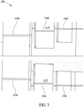
- Figure 3 is an image 300 of three pairs of structure light patterns as lines 314a, 314b; 314c, 314d; 314e, 314f (collectively 314) of light, returned from an object at three respective distances or ranges R, according to at least one illustrated embodiment.
- the lines 314 were captured with a light bandpass filter (e.g ., red filter) removed and exposure time increased to facilitate human perception of the lines.
- a light bandpass filter e.g ., red filter
- a first pair of lines 314a, 314b are produced by reflection from the first and the second angled reflective portions or reflectors 112a, 112b, respectively, and are spaced relatively close together as compared to a second pair of lines 314c, 314d.
- the second pair of lines 314c, 314d are produced by reflection from the first and the second angled reflective portions or reflectors 112a, 112b, respectively, and are spaced relatively close together as compared to a third pair of lines 314e, 314f.
- the third pair of lines 314e, 314f are produced by reflection from the first and the second angled reflective portions or reflectors 112a, 112b, respectively.
- the spacing between the lines 314 in each pair is indicative of a range R of the object from the system (e.g ., distance between a portion or surface of the object and the gap 250 ( Figure 2 ) between the first and the second angled reflective portions or reflectors 112a, 112b).
- the processor-based circuitry 118 may, for example, identify a single point or set of points in a three-dimensional (3D) point cloud.
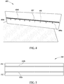
- Figure 4 is an isometric view of a calibration template 400 which can be used to calibrate the system of Figure 1 at each of a plurality of ranges or distances, according to at least one illustrated embodiment.
- the calibration template 400 may, for example, include an elongated line 402 that extends in first direction (e.g ., horizontally in Figure 4 ), with a plurality of shorter lines 404a, 404b, ... 404n (only three called out, collectively 404) that extend laterally ( e.g ., vertically in Figure 4 ) from the elongated line 402 at a defined spacing.
- the calibration template 400 may optionally include a scale (e.g ., set of demarcations with respective values spaced at defined intervals) 406 that extend along the elongated line 402.
- Figure 5 is a calibration image 500 of structured light patterns in the form of lines 552, 554 of light returned from the calibration template 400 of Figure 4 , according to at least one illustrated embodiment.
- each of the lines 552, 554 includes a number of gaps (e.g ., black vertical bar or stripe) 502a, 502b (only two called out) which results from the light (e.g ., laser) beam passing across of the shorter lines 404 ( Figure 4 ) of the calibration target.
- the centers of these gaps 502a, 502b are determined to calibrate for the width W of an object ( i.e., dimension along a Y-axis).
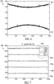
- Figure 6 is a graph 600 of the calibration image 500 ( Figure 5 ) after locating a center of the lines 552, 554, according to at least one illustrated embodiment.
- the graph 600 includes first and second plots 652, 654, corresponding to lines 552, 554, respectively, of the calibration image 500.
- an intensity of each of the lines 552, 554 is plotted for various positions ( e.g ., pixels) along a horizontal axis of the graph 600.
- a curvature in the plots 652, 654 is caused by lens distortion and is not otherwise indicative of a dimension ( e.g ., range R, width W) related to an object (e.g ., calibration template 400).
- the system is calibrated for "Y” and "Z” by finding a centroid of each of lines 552, 554 (e.g ., laser line) imaged using a target (e.g ., calibration template 400 of Figure 4 ) positioned at known ranges.
- a target e.g ., calibration template 400 of Figure 4
- an overdetermined system of equations was solved using a least squares (MATLAB " ⁇ ") approach, to generate the calibration factors for dimensions along both the Z-axis and the Y-axis.
- MATLAB " ⁇ " a least squares
- Figure 7 is a graph 700 of range R calibrations at five distances or ranges R to the calibration template 400, according to at least one illustrated embodiment.
- the graph 700 shows a first calibration fit 756a at a range of 570 mm, a second calibration fit 756b at a range of 803 mm, a third calibration fit 756c at a range of 1035 mm, a fourth calibration fit 756d at a range of 1268 mm, and a fifth calibration fit 756e at a range of 1500 mm.
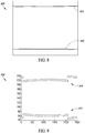
- Figure 8 is an image 800 of two instances of a structured light pattern (e.g., laser line) in the form of lines 852, 854 captured by the light sensor 110 of Figure 1 , after being returned from an object 104 ( Figure 1 ) and reflection by the two angled reflectors 112a, 112b ( Figures 1 , 2 ), according to at least one illustrated embodiment.
- the object 104 is a single wood box with dimensions of 152.2 mm by 457.1 mm by 304.6 mm.
- Figure 9 is a graph 900 showing a result of finding the centroid of the two instances of the structured light pattern in the form of lines 852, 854 of Figure 8 detected by the light sensor 110 ( Figure 1 ), according to at least one illustrated embodiment.
- the graph 900 includes first and second plots 952, 954, corresponding to lines 852, 854, respectively, of the image 800.
- an intensity of each of the lines 552, 554 is plotted for various positions ( e.g ., pixels) along a horizontal axis of the graph 600.
- a slight curvature in the plots 952, 954 is caused by lens distortion and is not otherwise indicative of a dimension ( e.g ., range R, width W) related to an object (e.g ., calibration template 400).
- Figure 10 is a graph 1000 of calibrated results from two instances of a structure light pattern in the form of lines ( e.g ., laser lines) 852, 854 ( Figure 8 ), according to at least one illustrated embodiment.
- lines e.g ., laser lines
- Figure 8 Figure 8
- a set of blue points 1052 and red points 1054 are the calibrated results from a bottom line 852 and a top line 854, respectively.
- a set of green points 1056 are an average of the blue and red points 1052, 1054.
- the object in this instance is a box with actual dimensions of 152 mm tall and 457 mm wide.
- the graph 1000 shows some slight offset between blue points and the red points, which may be the result of a change to the parallax angle in between calibration and run-time when the image of the object ( e.g ., box) was captured.
- Figure 11 is a graph 1100 of showing a result of finding a centroid of the two instances of a structure light pattern in the form of lines ( e.g ., laser scan) 1152, 1154 detected by a light sensor ( e.g ., light sensor 110 of Figure 1 ) returned from a box which has a significant variation in reflectance across a surface thereof, according to at least one illustrated embodiment.
- lines e.g ., laser scan
- a light sensor e.g ., light sensor 110 of Figure 1
- An object for example a box, that has significant variation in reflectance typically results in significant error in finding a laser centroid, and hence results in error in determined dimensions (e.g ., range, distance, height, width).
- the variation in reflectance can be caused by a variety of factors, for example printing ( e.g ., text, graphics), tape or other film, and/or dirt or debris on the surface being scanned.
- the magnitude of the problem is proportional to a width of the laser line or stripe. Relatively more narrow laser lines or stripes are of course more immune to this problem, however it is difficult to implement a narrow stripe over a large working range.
- Figure 12 is a graph 1200 of calibrated results from two instances of a structure light pattern in the form of lines ( e.g ., laser lines) 1152, 1154 ( Figure 11 ), according to at least one illustrated embodiment.
- lines e.g ., laser lines
- a set of blue points 1252 and red points 1254 are the calibrated results from a bottom line 1152 and a top line 1154, respectively.
- a set of green points 1256 are an average of the blue and red points 1252, 1254.
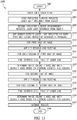
- Figure 13 is a flowchart diagram showing a method 1300 of operating a system to determine dimensions associated with an object, according to at least one illustrated embodiment.
- the method 1300 can be executed by the system generally described herein.
- the method 1300 can include additional acts, may omit some acts, and/or may perform one or more acts in a different order than the order set out in Figure 13 .
- the method 1300 starts for example on starting up or powering of a system or device, or in response to a user input or invocation by a calling routine, program, function call or subprogram.
- a light source e.g ., laser, LEDs
- the light may be emitted as a structured light pattern or may be reflected or diffracted as a structure light pattern.
- a first reflective surface reflects light returned from an object in an environment.
- the second reflective surface oriented at a non-zero angle with respect to the first reflective surface, concurrently reflects light returned from an object in the environment.
- a light sensor e.g ., a linear image sensor detects the light reflected from the object in the environment via both the first and the second reflective surfaces in parallax.
- a first half of an image captured by the light sensor is processed via circuitry, for example a lower half of the image containing the image of one instance of the structured light pattern (e.g ., laser line) reflected by one of the reflective portions or reflectors.
- the structured light pattern e.g ., laser line
- the circuitry applies a threshold and one or more filters to the first half of the image, for example to clean up and isolate the image of the instance of the structured light pattern (e.g ., laser line or stripe) in the first half of the image.
- the circuitry may apply a brightness threshold and/or a moving average filter or low pass filter to the image data.
- each column of pixels is processed, for example successively column by column.
- Each column extends in a direction in the image that is parallel to the X-axis, and columns are successively encountered along a direction in the image that is parallel with the Y-axis.
- the circuitry finds the centroid (e.g ., peak, center along axis of column or thickness of line) of the structured light pattern (e.g ., laser line) at 1318.
- the circuitry determines a range (z) and width distance across the belt (y) based on centroid location and column at 1320.
- the circuitry may look up ( e.g ., in look-up table) the corresponding range R and/or width W or calculate ( e.g ., solve defined equation(s)) range R and/or width W.
- a second half of the image captured by the light sensor is processed via circuitry, for example an upper half of the image containing the image of one instance of the structured light pattern (e.g ., laser line) reflected by one of the reflective portions or reflectors.
- the structured light pattern e.g ., laser line
- the circuitry applies a threshold and one or more filters to the second half of the image, for example to clean up and isolate the image of the instance of the structured light pattern (e.g ., laser line or stripe) in the second half of the image.
- a threshold and one or more filters to the second half of the image, for example to clean up and isolate the image of the instance of the structured light pattern (e.g ., laser line or stripe) in the second half of the image.
- each column of pixels is processed, for example successively column by column.
- the circuitry finds the centroid (e.g ., peak, center along axis of column or thickness of line) of the structured light pattern (e.g. , laser line) at 1328.
- the circuitry determines a range (z) and width distance across the belt (y) based on centroid location and column at 1330. For example, the circuitry may look up the corresponding range R and/or width W or calculate range R and/or width W.
- the circuitry averages the results from the processing of the first and the second halves of the image.
- the method 1300 terminates at 1334, for example until invoked again. Alternatively, the method 1300 may repeat continually, for instance periodically. In some implementations, the method 1300 may be executed as a thread on a multi-threaded processor.
- logic or information can be stored on any computer-readable medium for use by or in connection with any computer and/or processor related system or method.
- a memory is a computer-readable medium that is an electronic, magnetic, optical, or other physical device or means that contains or stores a computer and/or processor program.
- Logic and/or the information can be embodied in any computer-readable medium for use by or in connection with an instruction execution system, apparatus, or device, such as a computer-based system, processor-containing system, or other system that can fetch the instructions from the instruction execution system, apparatus, or device and execute the instructions associated with logic and/or information.
- a "computer-readable medium” can be any means that can store, communicate, propagate, or transport the program associated with logic and/or information for use by or in connection with the instruction execution system, apparatus, and/or device.
- the computer-readable medium can be, for example, but is not limited to, an electronic, magnetic, optical, electromagnetic, infrared, or semiconductor system, apparatus, device, or propagation medium.
- the computer-readable medium would include the following: an electrical connection having one or more wires, a portable computer diskette (magnetic, compact flash card, secure digital, or the like), a random access memory (RAM), a read-only memory (ROM), an erasable programmable read-only memory (EPROM, EEPROM, or Flash memory), an optical fiber, and a portable compact disc read-only memory (CDROM).
- a portable computer diskette magnetic, compact flash card, secure digital, or the like
- RAM random access memory
- ROM read-only memory
- EPROM erasable programmable read-only memory
- CDROM portable compact disc read-only memory
- the computer-readable medium could even be paper or another suitable medium upon which the program associated with logic and/or information is printed, as the program can be electronically captured, via for instance optical scanning of the paper or other medium, then compiled, interpreted or otherwise processed in a suitable manner if necessary, and then stored in memory.
- non-transitory signal bearing media include, but are not limited to, the following: recordable type media such as floppy disks, hard disk drives, CD ROMs, digital tape, and computer memory; and transitory or transmission type media such as digital and analog communication links using TDM or IP based communication links ( e.g ., packet links).
Landscapes
- Physics & Mathematics (AREA)
- General Physics & Mathematics (AREA)
- Engineering & Computer Science (AREA)
- Computer Vision & Pattern Recognition (AREA)
- Electromagnetism (AREA)
- Radar, Positioning & Navigation (AREA)
- Remote Sensing (AREA)
- Length Measuring Devices By Optical Means (AREA)
Claims (14)
- Système, comprenant :une source de lumière (108) configurée pour générer un motif lumineux structuré et opérationnelle pour émettre ce motif lumineux structuré vers l'extérieur dans un environnement ;une première surface réfléchissante (112a) et une deuxième surface réfléchissante (112b), les première et deuxième surfaces réfléchissantes (112a, 112b) positionnées par rapport à la source de lumière (108) pour recevoir simultanément de la lumière renvoyée d'un objet (104) dans l'environnement en guise de motif lumineux structuré (114), la deuxième surface réfléchissante (112b) orientée selon un angle différent de zéro par rapport à la première surface réfléchissante (112a) ;un capteur de lumière (110) positionné pour détecter simultanément, en parallaxe, de la lumière réfléchie par l'objet (104) dans l'environnement via à la fois les première et deuxième surfaces réfléchissantes (112a, 112b), respectivement en tant que première instance du motif lumineux structuré (114) réfléchie par la première surface réfléchissante (112a) et deuxième instance du motif lumineux structuré (114) réfléchie par la deuxième surface réfléchissante (112b) ; etau moins un processeur (134, 136, 138) couplé par communications avec le capteur de lumière (110), et qui est configuré pour corréler une position relative des première et deuxième instances du motif lumineux structuré (114) détectées par le capteur de lumière (110) et est configuré pour déterminer au moins une dimension se rapportant à l'objet (104) sur la base au moins en partie de la corrélation des positions relatives des première et deuxième instances du motif lumineux structuré (114) détectées par le capteur de lumière (110) ;caractérisé en ce quel'angle différent de zéro entre les première et deuxième surfaces réfléchissantes (112a, 112b) est un angle obtus qui est inférieur à 180 degrés.
- Système selon la revendication 1, dans lequel la première surface réfléchissante (112a) est une surface plane qui a un bord interne respectif et la deuxième surface réfléchissante (112b) est une surface plane qui a un bord interne respectif, la deuxième surface réfléchissante (112b) espacée de la première surface réfléchissante (112a) avec un espace (250) entre les bords internes respectifs des première et deuxième surfaces réfléchissantes (112a, 112b), et la lumière passe à travers l'espace (250) vers l'extérieur dans l'environnement.
- Système selon l'une quelconque des revendications précédentes dans lequel le capteur de lumière (110) est un unique capteur de lumière bidimensionnel (110), et comprenant en outre :
au moins un miroir positionné par rapport à la source de lumière (108) et opérationnel pour au moins l'un parmi une rotation ou un pivotement pour produire le motif lumineux structuré (114). - Système selon l'une quelconque des revendications précédentes dans lequel l'au moins une dimension se rapportant à l'objet (104) déterminée par l'au moins un processeur (134, 136, 138) inclut au moins l'une parmi une distance jusqu'à une surface de l'objet (104), une hauteur (H) de l'objet (104), une largeur (W) de l'objet (104) et une longueur (L) de l'objet (104).
- Système selon l'une quelconque des revendications précédentes dans lequel pour corréler une position relative des première et deuxième instances du motif lumineux structuré (114) détectées par le capteur de lumière (110), l'au moins un processeur (134, 136, 138) :pour la première instance du motif lumineux structuré (114), détermine à chacune d'une pluralité de positions le long de la première instance du motif lumineux structuré (114) un centroïde respectif pour la première instance du motif lumineux structuré (114) à la position respective ; etpour la deuxième instance du motif lumineux structuré (114), détermine à chacune d'une pluralité de positions le long de la deuxième instance du motif lumineux structuré (114) un centroïde respectif pour la deuxième instance du motif lumineux structuré (114) à la position respective.
- Système selon la revendication 5 dans lequel pour déterminer au moins une dimension se rapportant à l'objet (104) sur la base au moins en partie de la corrélation des positions relatives des première et deuxième instances du motif lumineux structuré (114), l'au moins un processeur (134, 136, 138) détermine une étendue (R) jusqu'à l'objet (104) sur la base des centroïdes déterminés le long des première et deuxième instances du motif lumineux structuré (114).
- Système selon la revendication 5 ou 6 dans lequel l'au moins un processeur (134, 136, 138) détermine l'étendue (R) jusqu'à l'objet (104) sur la base au moins en partie des centroïdes déterminés pour chacune des positions le long des première et deuxième instances du motif lumineux structuré (114) et sur la base en outre d'un ensemble d'informations d'étalonnage.
- Système selon les revendications 6 ou 7 dans lequel l'au moins un processeur (134, 136, 138) établit la moyenne des résultats de l'étendue déterminée (R) jusqu'à l'objet (104) sur la base des centroïdes déterminés pour chacune des positions le long des première et deuxième instances du motif lumineux structuré (114).
- Système selon l'une quelconque des revendications 6 à 8 dans lequel pour déterminer au moins une dimension se rapportant à l'objet (104) sur la base au moins en partie de la corrélation des positions relatives des première et deuxième instances du motif lumineux structuré (114), l'au moins un processeur (134, 136, 138) détermine une hauteur (H) de l'objet (104) sur la base de l'étendue déterminée (R) et de la distance jusqu'à une surface sur laquelle l'objet (104) est supporté et/ou détermine une largeur (W) de l'objet (104) sur la base des centroïdes déterminés.
- Système selon l'une quelconque des revendications 5 à 9 dans lequel l'au moins un processeur (134, 136, 138) détermine une largeur (W) de l'objet (104) sur la base au moins en partie des centroïdes déterminés pour chacune des positions le long des première et deuxième instances du motif lumineux structuré (114).
- Système selon la revendication 10 dans lequel l'au moins un processeur (134, 136, 138) établit la moyenne des résultats de la largeur déterminée (W) de l'objet (104) sur la base des centroïdes déterminés pour chacune des positions le long des première et deuxième instances du motif lumineux structuré (114).
- Système selon les revendications 10 ou 11 dans lequel l'au moins un processeur (134, 136, 138) détermine la largeur (W) de l'objet (104) sur la base en outre d'un ensemble d'informations d'étalonnage.
- Système selon l'une quelconque des revendications précédentes dans lequel la source de lumière (108) est un laser, la lumière structurée est un motif linéaire de lumière laser, et comprenant en outre :
une lentille et un filtre passe-bande dans un trajet optique du capteur de lumière (110). - Procédé, comprenant :l'émission d'un faisceau de lumière par une source de lumière (108) ;la réflexion de lumière renvoyée d'un objet (104) dans un environnement par une première surface réfléchissante (112a) ;la réflexion simultanée de la lumière renvoyée par l'objet (104) dans l'environnement par une deuxième surface réfléchissante (112b), la deuxième surface réfléchissante (112b) orientée selon un angle différent de zéro par rapport à la première surface réfléchissante (112a) ;la détection par un capteur de lumière (110) de la lumière réfléchie par l'objet (104) dans l'environnement via à la fois les première et deuxième surfaces réfléchissantes (112a, 112b) en parallaxe, respectivement en tant que première instance d'un motif lumineux structuré (114) réfléchie par la première surface réfléchissante (112a) et deuxième instance du motif lumineux structuré (114) réfléchie par la deuxième surface réfléchissante (112b) ; et la détermination par au moins un processeur (134, 136, 138) couplé par communications avec le capteur de lumière (110), d'au moins une dimension se rapportant à l'objet (104) sur la base au moins en partie d'une corrélation d'une position relative des première et deuxième instances du motif lumineux structuré détecté par le capteur de lumière (110) ;caractérisé en ce quel'angle différent de zéro entre les première et deuxième surfaces réfléchissantes (112a, 112b) est un angle obtus qui est inférieur à 180 degrés, dans lequel la première surface réfléchissante (112a) est une surface plane qui a un bord interne respectif et la deuxième surface réfléchissante (112b) est une surface plane qui a un bord interne respectif, la deuxième surface réfléchissante (112b) espacée de la première surface réfléchissante (112a) avec un espace (250) entre les bords internes respectifs des première et deuxième surfaces réfléchissantes (112a, 112b), et la lumière émise est dirigée de telle sorte qu'elle passe à travers l'espace (250) vers l'extérieur dans l'environnement.
Applications Claiming Priority (1)
| Application Number | Priority Date | Filing Date | Title |
|---|---|---|---|
| US15/244,831 US10480928B2 (en) | 2016-08-23 | 2016-08-23 | Parallax-based determination of dimension(s) related to an object |
Publications (2)
| Publication Number | Publication Date |
|---|---|
| EP3287737A1 EP3287737A1 (fr) | 2018-02-28 |
| EP3287737B1 true EP3287737B1 (fr) | 2020-02-05 |
Family
ID=59858482
Family Applications (1)
| Application Number | Title | Priority Date | Filing Date |
|---|---|---|---|
| EP17187195.7A Active EP3287737B1 (fr) | 2016-08-23 | 2017-08-22 | Système et méthode de détermination basée sur un parallaxe de dimension relative à un objet |
Country Status (2)
| Country | Link |
|---|---|
| US (1) | US10480928B2 (fr) |
| EP (1) | EP3287737B1 (fr) |
Families Citing this family (3)
| Publication number | Priority date | Publication date | Assignee | Title |
|---|---|---|---|---|
| KR102144125B1 (ko) * | 2014-01-14 | 2020-08-12 | 한국전자통신연구원 | 우편물 크기 측정 및 우편물 정보 획득 장치 및 방법 |
| KR102520639B1 (ko) | 2018-05-02 | 2023-04-11 | 삼성디스플레이 주식회사 | 입력 감지 장치 및 이를 포함하는 표시 장치 |
| CN111156899B (zh) * | 2020-02-18 | 2022-04-12 | 广东博智林机器人有限公司 | 一种视觉测量装置、方法及机器人 |
Family Cites Families (10)
| Publication number | Priority date | Publication date | Assignee | Title |
|---|---|---|---|---|
| US3796492A (en) | 1971-06-01 | 1974-03-12 | Autech Corp | Laser dimension comparator |
| US3918816A (en) | 1974-04-22 | 1975-11-11 | Autech Corp | Tire inspection apparatus |
| US4737032A (en) * | 1985-08-26 | 1988-04-12 | Cyberware Laboratory, Inc. | Surface mensuration sensor |
| US4929843A (en) | 1989-06-28 | 1990-05-29 | General Electric Company | Apparatus and method for determining a dimension of an object |
| US4949843A (en) | 1989-08-31 | 1990-08-21 | Stokes William T | One-piece multi-pocketed storage device |
| US6028672A (en) | 1996-09-30 | 2000-02-22 | Zheng J. Geng | High speed three dimensional imaging method |
| US6271918B2 (en) | 1999-02-04 | 2001-08-07 | National Research Council Of Canada | Virtual multiple aperture 3-D range sensor |
| US6897966B2 (en) | 2001-05-25 | 2005-05-24 | Poster-Miller, Inc. | Non-contacting mensuration system |
| US6629409B2 (en) * | 2001-06-20 | 2003-10-07 | Ford Global Technologies, Llc | System and method for determining set point location for oxidant-based engine air/fuel control strategy |
| US8483444B2 (en) | 2007-06-15 | 2013-07-09 | Kabushiki Kaisha Toshiba | Apparatus for inspecting and measuring object to be measured |
-
2016
- 2016-08-23 US US15/244,831 patent/US10480928B2/en active Active
-
2017
- 2017-08-22 EP EP17187195.7A patent/EP3287737B1/fr active Active
Non-Patent Citations (1)
| Title |
|---|
| None * |
Also Published As
| Publication number | Publication date |
|---|---|
| US20180058839A1 (en) | 2018-03-01 |
| EP3287737A1 (fr) | 2018-02-28 |
| US10480928B2 (en) | 2019-11-19 |
Similar Documents
| Publication | Publication Date | Title |
|---|---|---|
| US10769806B2 (en) | Dimensional acquisition of packages | |
| US11310479B2 (en) | Non-uniform spatial resource allocation for depth mapping | |
| US10096131B2 (en) | Dimensional acquisition of packages | |
| EP2839238B1 (fr) | Dispositif de balayage 3d utilisant des images partielles fusionnées | |
| US9134117B2 (en) | Distance measuring system and distance measuring method | |
| CN103443001B (zh) | 用于运动中的物体的光学识别的方法 | |
| JP7855017B2 (ja) | 投影パターン内のエピポーラ線距離からの自動較正 | |
| KR102833045B1 (ko) | 능동형 광학 센서 시스템의 측정 데이터를 필터링하는 기법 | |
| CN115461643A (zh) | 用于对象深度测量的照射图案 | |
| EP3287737A1 (fr) | Détermination basée sur la parallaxe de dimension(s) relatives à un objet | |
| CN101939618A (zh) | 光学三角测量 | |
| US20070210240A1 (en) | Multiple axis multipoint non-contact measurement system | |
| US20220196386A1 (en) | Three-dimensional scanner with event camera | |
| US11920918B2 (en) | One shot calibration | |
| US20240418503A1 (en) | Recalibration of a 3d detector based on structured light | |
| US20250218040A1 (en) | Calibration of depth map generating system | |
| US12450761B2 (en) | Imaging arrangement and corresponding methods and systems for depth map generation | |
| KR102927740B1 (ko) | 메타표면을 포함하는 구조화 광 깊이 센서 | |
| Bender et al. | A Hand-held Laser Scanner based on Multi-camera Stereo-matching | |
| CA2536411C (fr) | Systeme de mesure sans contact multipoint a axes multiples | |
| US20240284031A1 (en) | Emitter array with two or more independently driven areas | |
| CN120359437A (zh) | 成像装置及其方法 | |
| Boehnke et al. | Triangulation based 3D laser sensor accuracy and calibration [articol] |
Legal Events
| Date | Code | Title | Description |
|---|---|---|---|
| PUAI | Public reference made under article 153(3) epc to a published international application that has entered the european phase |
Free format text: ORIGINAL CODE: 0009012 |
|
| STAA | Information on the status of an ep patent application or granted ep patent |
Free format text: STATUS: THE APPLICATION HAS BEEN PUBLISHED |
|
| AK | Designated contracting states |
Kind code of ref document: A1 Designated state(s): AL AT BE BG CH CY CZ DE DK EE ES FI FR GB GR HR HU IE IS IT LI LT LU LV MC MK MT NL NO PL PT RO RS SE SI SK SM TR |
|
| AX | Request for extension of the european patent |
Extension state: BA ME |
|
| STAA | Information on the status of an ep patent application or granted ep patent |
Free format text: STATUS: REQUEST FOR EXAMINATION WAS MADE |
|
| 17P | Request for examination filed |
Effective date: 20180823 |
|
| RBV | Designated contracting states (corrected) |
Designated state(s): AL AT BE BG CH CY CZ DE DK EE ES FI FR GB GR HR HU IE IS IT LI LT LU LV MC MK MT NL NO PL PT RO RS SE SI SK SM TR |
|
| REG | Reference to a national code |
Ref country code: DE Ref legal event code: R079 Ref document number: 602017011336 Country of ref document: DE Free format text: PREVIOUS MAIN CLASS: G01B0011240000 Ipc: G01B0011250000 |
|
| GRAP | Despatch of communication of intention to grant a patent |
Free format text: ORIGINAL CODE: EPIDOSNIGR1 |
|
| STAA | Information on the status of an ep patent application or granted ep patent |
Free format text: STATUS: GRANT OF PATENT IS INTENDED |
|
| RIC1 | Information provided on ipc code assigned before grant |
Ipc: G01B 11/25 20060101AFI20190729BHEP |
|
| INTG | Intention to grant announced |
Effective date: 20190816 |
|
| GRAS | Grant fee paid |
Free format text: ORIGINAL CODE: EPIDOSNIGR3 |
|
| GRAA | (expected) grant |
Free format text: ORIGINAL CODE: 0009210 |
|
| STAA | Information on the status of an ep patent application or granted ep patent |
Free format text: STATUS: THE PATENT HAS BEEN GRANTED |
|
| AK | Designated contracting states |
Kind code of ref document: B1 Designated state(s): AL AT BE BG CH CY CZ DE DK EE ES FI FR GB GR HR HU IE IS IT LI LT LU LV MC MK MT NL NO PL PT RO RS SE SI SK SM TR |
|
| REG | Reference to a national code |
Ref country code: GB Ref legal event code: FG4D |
|
| REG | Reference to a national code |
Ref country code: AT Ref legal event code: REF Ref document number: 1230226 Country of ref document: AT Kind code of ref document: T Effective date: 20200215 |
|
| REG | Reference to a national code |
Ref country code: DE Ref legal event code: R096 Ref document number: 602017011336 Country of ref document: DE |
|
| REG | Reference to a national code |
Ref country code: IE Ref legal event code: FG4D |
|
| REG | Reference to a national code |
Ref country code: CH Ref legal event code: EP |
|
| REG | Reference to a national code |
Ref country code: NL Ref legal event code: MP Effective date: 20200205 |
|
| PG25 | Lapsed in a contracting state [announced via postgrant information from national office to epo] |
Ref country code: NO Free format text: LAPSE BECAUSE OF FAILURE TO SUBMIT A TRANSLATION OF THE DESCRIPTION OR TO PAY THE FEE WITHIN THE PRESCRIBED TIME-LIMIT Effective date: 20200505 Ref country code: FI Free format text: LAPSE BECAUSE OF FAILURE TO SUBMIT A TRANSLATION OF THE DESCRIPTION OR TO PAY THE FEE WITHIN THE PRESCRIBED TIME-LIMIT Effective date: 20200205 Ref country code: PT Free format text: LAPSE BECAUSE OF FAILURE TO SUBMIT A TRANSLATION OF THE DESCRIPTION OR TO PAY THE FEE WITHIN THE PRESCRIBED TIME-LIMIT Effective date: 20200628 Ref country code: RS Free format text: LAPSE BECAUSE OF FAILURE TO SUBMIT A TRANSLATION OF THE DESCRIPTION OR TO PAY THE FEE WITHIN THE PRESCRIBED TIME-LIMIT Effective date: 20200205 |
|
| REG | Reference to a national code |
Ref country code: LT Ref legal event code: MG4D |
|
| PG25 | Lapsed in a contracting state [announced via postgrant information from national office to epo] |
Ref country code: IS Free format text: LAPSE BECAUSE OF FAILURE TO SUBMIT A TRANSLATION OF THE DESCRIPTION OR TO PAY THE FEE WITHIN THE PRESCRIBED TIME-LIMIT Effective date: 20200605 Ref country code: BG Free format text: LAPSE BECAUSE OF FAILURE TO SUBMIT A TRANSLATION OF THE DESCRIPTION OR TO PAY THE FEE WITHIN THE PRESCRIBED TIME-LIMIT Effective date: 20200505 Ref country code: HR Free format text: LAPSE BECAUSE OF FAILURE TO SUBMIT A TRANSLATION OF THE DESCRIPTION OR TO PAY THE FEE WITHIN THE PRESCRIBED TIME-LIMIT Effective date: 20200205 Ref country code: GR Free format text: LAPSE BECAUSE OF FAILURE TO SUBMIT A TRANSLATION OF THE DESCRIPTION OR TO PAY THE FEE WITHIN THE PRESCRIBED TIME-LIMIT Effective date: 20200506 Ref country code: SE Free format text: LAPSE BECAUSE OF FAILURE TO SUBMIT A TRANSLATION OF THE DESCRIPTION OR TO PAY THE FEE WITHIN THE PRESCRIBED TIME-LIMIT Effective date: 20200205 Ref country code: LV Free format text: LAPSE BECAUSE OF FAILURE TO SUBMIT A TRANSLATION OF THE DESCRIPTION OR TO PAY THE FEE WITHIN THE PRESCRIBED TIME-LIMIT Effective date: 20200205 |
|
| PG25 | Lapsed in a contracting state [announced via postgrant information from national office to epo] |
Ref country code: NL Free format text: LAPSE BECAUSE OF FAILURE TO SUBMIT A TRANSLATION OF THE DESCRIPTION OR TO PAY THE FEE WITHIN THE PRESCRIBED TIME-LIMIT Effective date: 20200205 |
|
| PG25 | Lapsed in a contracting state [announced via postgrant information from national office to epo] |
Ref country code: LT Free format text: LAPSE BECAUSE OF FAILURE TO SUBMIT A TRANSLATION OF THE DESCRIPTION OR TO PAY THE FEE WITHIN THE PRESCRIBED TIME-LIMIT Effective date: 20200205 Ref country code: ES Free format text: LAPSE BECAUSE OF FAILURE TO SUBMIT A TRANSLATION OF THE DESCRIPTION OR TO PAY THE FEE WITHIN THE PRESCRIBED TIME-LIMIT Effective date: 20200205 Ref country code: RO Free format text: LAPSE BECAUSE OF FAILURE TO SUBMIT A TRANSLATION OF THE DESCRIPTION OR TO PAY THE FEE WITHIN THE PRESCRIBED TIME-LIMIT Effective date: 20200205 Ref country code: CZ Free format text: LAPSE BECAUSE OF FAILURE TO SUBMIT A TRANSLATION OF THE DESCRIPTION OR TO PAY THE FEE WITHIN THE PRESCRIBED TIME-LIMIT Effective date: 20200205 Ref country code: SK Free format text: LAPSE BECAUSE OF FAILURE TO SUBMIT A TRANSLATION OF THE DESCRIPTION OR TO PAY THE FEE WITHIN THE PRESCRIBED TIME-LIMIT Effective date: 20200205 Ref country code: EE Free format text: LAPSE BECAUSE OF FAILURE TO SUBMIT A TRANSLATION OF THE DESCRIPTION OR TO PAY THE FEE WITHIN THE PRESCRIBED TIME-LIMIT Effective date: 20200205 Ref country code: SM Free format text: LAPSE BECAUSE OF FAILURE TO SUBMIT A TRANSLATION OF THE DESCRIPTION OR TO PAY THE FEE WITHIN THE PRESCRIBED TIME-LIMIT Effective date: 20200205 Ref country code: DK Free format text: LAPSE BECAUSE OF FAILURE TO SUBMIT A TRANSLATION OF THE DESCRIPTION OR TO PAY THE FEE WITHIN THE PRESCRIBED TIME-LIMIT Effective date: 20200205 |
|
| REG | Reference to a national code |
Ref country code: DE Ref legal event code: R097 Ref document number: 602017011336 Country of ref document: DE |
|
| REG | Reference to a national code |
Ref country code: AT Ref legal event code: MK05 Ref document number: 1230226 Country of ref document: AT Kind code of ref document: T Effective date: 20200205 |
|
| PLBE | No opposition filed within time limit |
Free format text: ORIGINAL CODE: 0009261 |
|
| STAA | Information on the status of an ep patent application or granted ep patent |
Free format text: STATUS: NO OPPOSITION FILED WITHIN TIME LIMIT |
|
| 26N | No opposition filed |
Effective date: 20201106 |
|
| PG25 | Lapsed in a contracting state [announced via postgrant information from national office to epo] |
Ref country code: AT Free format text: LAPSE BECAUSE OF FAILURE TO SUBMIT A TRANSLATION OF THE DESCRIPTION OR TO PAY THE FEE WITHIN THE PRESCRIBED TIME-LIMIT Effective date: 20200205 Ref country code: IT Free format text: LAPSE BECAUSE OF FAILURE TO SUBMIT A TRANSLATION OF THE DESCRIPTION OR TO PAY THE FEE WITHIN THE PRESCRIBED TIME-LIMIT Effective date: 20200205 |
|
| PG25 | Lapsed in a contracting state [announced via postgrant information from national office to epo] |
Ref country code: SI Free format text: LAPSE BECAUSE OF FAILURE TO SUBMIT A TRANSLATION OF THE DESCRIPTION OR TO PAY THE FEE WITHIN THE PRESCRIBED TIME-LIMIT Effective date: 20200205 Ref country code: PL Free format text: LAPSE BECAUSE OF FAILURE TO SUBMIT A TRANSLATION OF THE DESCRIPTION OR TO PAY THE FEE WITHIN THE PRESCRIBED TIME-LIMIT Effective date: 20200205 |
|
| PG25 | Lapsed in a contracting state [announced via postgrant information from national office to epo] |
Ref country code: MC Free format text: LAPSE BECAUSE OF FAILURE TO SUBMIT A TRANSLATION OF THE DESCRIPTION OR TO PAY THE FEE WITHIN THE PRESCRIBED TIME-LIMIT Effective date: 20200205 |
|
| REG | Reference to a national code |
Ref country code: CH Ref legal event code: PL |
|
| PG25 | Lapsed in a contracting state [announced via postgrant information from national office to epo] |
Ref country code: CH Free format text: LAPSE BECAUSE OF NON-PAYMENT OF DUE FEES Effective date: 20200831 Ref country code: LI Free format text: LAPSE BECAUSE OF NON-PAYMENT OF DUE FEES Effective date: 20200831 Ref country code: LU Free format text: LAPSE BECAUSE OF NON-PAYMENT OF DUE FEES Effective date: 20200822 |
|
| REG | Reference to a national code |
Ref country code: BE Ref legal event code: MM Effective date: 20200831 |
|
| PG25 | Lapsed in a contracting state [announced via postgrant information from national office to epo] |
Ref country code: FR Free format text: LAPSE BECAUSE OF NON-PAYMENT OF DUE FEES Effective date: 20200831 |
|
| PG25 | Lapsed in a contracting state [announced via postgrant information from national office to epo] |
Ref country code: IE Free format text: LAPSE BECAUSE OF NON-PAYMENT OF DUE FEES Effective date: 20200822 Ref country code: BE Free format text: LAPSE BECAUSE OF NON-PAYMENT OF DUE FEES Effective date: 20200831 |
|
| GBPC | Gb: european patent ceased through non-payment of renewal fee |
Effective date: 20210822 |
|
| PG25 | Lapsed in a contracting state [announced via postgrant information from national office to epo] |
Ref country code: TR Free format text: LAPSE BECAUSE OF FAILURE TO SUBMIT A TRANSLATION OF THE DESCRIPTION OR TO PAY THE FEE WITHIN THE PRESCRIBED TIME-LIMIT Effective date: 20200205 Ref country code: MT Free format text: LAPSE BECAUSE OF FAILURE TO SUBMIT A TRANSLATION OF THE DESCRIPTION OR TO PAY THE FEE WITHIN THE PRESCRIBED TIME-LIMIT Effective date: 20200205 Ref country code: CY Free format text: LAPSE BECAUSE OF FAILURE TO SUBMIT A TRANSLATION OF THE DESCRIPTION OR TO PAY THE FEE WITHIN THE PRESCRIBED TIME-LIMIT Effective date: 20200205 |
|
| PG25 | Lapsed in a contracting state [announced via postgrant information from national office to epo] |
Ref country code: MK Free format text: LAPSE BECAUSE OF FAILURE TO SUBMIT A TRANSLATION OF THE DESCRIPTION OR TO PAY THE FEE WITHIN THE PRESCRIBED TIME-LIMIT Effective date: 20200205 Ref country code: AL Free format text: LAPSE BECAUSE OF FAILURE TO SUBMIT A TRANSLATION OF THE DESCRIPTION OR TO PAY THE FEE WITHIN THE PRESCRIBED TIME-LIMIT Effective date: 20200205 |
|
| PG25 | Lapsed in a contracting state [announced via postgrant information from national office to epo] |
Ref country code: GB Free format text: LAPSE BECAUSE OF NON-PAYMENT OF DUE FEES Effective date: 20210822 |
|
| P01 | Opt-out of the competence of the unified patent court (upc) registered |
Effective date: 20230528 |
|
| PGFP | Annual fee paid to national office [announced via postgrant information from national office to epo] |
Ref country code: DE Payment date: 20250820 Year of fee payment: 9 |