EP3287753B1 - Systeme und verfahren zur bestimmung einer kraftstoffffüllstandsmessung eines kraftstofftanks mit optischen sensoren - Google Patents
Systeme und verfahren zur bestimmung einer kraftstoffffüllstandsmessung eines kraftstofftanks mit optischen sensoren Download PDFInfo
- Publication number
- EP3287753B1 EP3287753B1 EP17182425.3A EP17182425A EP3287753B1 EP 3287753 B1 EP3287753 B1 EP 3287753B1 EP 17182425 A EP17182425 A EP 17182425A EP 3287753 B1 EP3287753 B1 EP 3287753B1
- Authority
- EP
- European Patent Office
- Prior art keywords
- fuel tank
- fuel
- optical sensors
- optical
- sensors
- Prior art date
- Legal status (The legal status is an assumption and is not a legal conclusion. Google has not performed a legal analysis and makes no representation as to the accuracy of the status listed.)
- Active
Links
Images


Classifications
-
- G—PHYSICS
- G01—MEASURING; TESTING
- G01F—MEASURING VOLUME, VOLUME FLOW, MASS FLOW OR LIQUID LEVEL; METERING BY VOLUME
- G01F23/00—Indicating or measuring liquid level or level of fluent solid material, e.g. indicating in terms of volume or indicating by means of an alarm
- G01F23/14—Indicating or measuring liquid level or level of fluent solid material, e.g. indicating in terms of volume or indicating by means of an alarm by measurement of pressure
-
- G—PHYSICS
- G01—MEASURING; TESTING
- G01F—MEASURING VOLUME, VOLUME FLOW, MASS FLOW OR LIQUID LEVEL; METERING BY VOLUME
- G01F23/00—Indicating or measuring liquid level or level of fluent solid material, e.g. indicating in terms of volume or indicating by means of an alarm
- G01F23/22—Indicating or measuring liquid level or level of fluent solid material, e.g. indicating in terms of volume or indicating by means of an alarm by measuring physical variables, other than linear dimensions, pressure or weight, dependent on the level to be measured, e.g. by difference of heat transfer of steam or water
- G01F23/28—Indicating or measuring liquid level or level of fluent solid material, e.g. indicating in terms of volume or indicating by means of an alarm by measuring physical variables, other than linear dimensions, pressure or weight, dependent on the level to be measured, e.g. by difference of heat transfer of steam or water by measuring the variations of parameters of electromagnetic or acoustic waves applied directly to the liquid or fluent solid material
- G01F23/284—Electromagnetic waves
- G01F23/292—Light, e.g. infrared or ultraviolet
-
- B—PERFORMING OPERATIONS; TRANSPORTING
- B64—AIRCRAFT; AVIATION; COSMONAUTICS
- B64D—EQUIPMENT FOR FITTING IN OR TO AIRCRAFT; FLIGHT SUITS; PARACHUTES; ARRANGEMENT OR MOUNTING OF POWER PLANTS OR PROPULSION TRANSMISSIONS IN AIRCRAFT
- B64D37/00—Arrangements in connection with fuel supply for power plant
-
- B—PERFORMING OPERATIONS; TRANSPORTING
- B64—AIRCRAFT; AVIATION; COSMONAUTICS
- B64D—EQUIPMENT FOR FITTING IN OR TO AIRCRAFT; FLIGHT SUITS; PARACHUTES; ARRANGEMENT OR MOUNTING OF POWER PLANTS OR PROPULSION TRANSMISSIONS IN AIRCRAFT
- B64D37/00—Arrangements in connection with fuel supply for power plant
- B64D37/005—Accessories not provided for in the groups B64D37/02 - B64D37/28
-
- B—PERFORMING OPERATIONS; TRANSPORTING
- B64—AIRCRAFT; AVIATION; COSMONAUTICS
- B64D—EQUIPMENT FOR FITTING IN OR TO AIRCRAFT; FLIGHT SUITS; PARACHUTES; ARRANGEMENT OR MOUNTING OF POWER PLANTS OR PROPULSION TRANSMISSIONS IN AIRCRAFT
- B64D37/00—Arrangements in connection with fuel supply for power plant
- B64D37/02—Tanks
-
- G—PHYSICS
- G01—MEASURING; TESTING
- G01F—MEASURING VOLUME, VOLUME FLOW, MASS FLOW OR LIQUID LEVEL; METERING BY VOLUME
- G01F23/00—Indicating or measuring liquid level or level of fluent solid material, e.g. indicating in terms of volume or indicating by means of an alarm
- G01F23/14—Indicating or measuring liquid level or level of fluent solid material, e.g. indicating in terms of volume or indicating by means of an alarm by measurement of pressure
- G01F23/18—Indicating, recording or alarm devices actuated electrically
Definitions
- the present disclosure relates generally to systems and methods for determining a fuel level measurement of a fuel tank, and more particularly to, determining a fuel level measurement of the fuel tank based on the outputs of optical sensors mounted inside the fuel tank.
- fuel probes include two concentric tubes that act as capacitors.
- Metal wires for the probes are inserted into a fuel tank, and redundant supports are provided for the wiring, which increases an overall weight of the system, and increases a manufacturing time of the system.
- US 5026984 discloses temperature, pressure and liquid level parameters which are sensed by a variable ratio fiber optic coupler sensor wherein the optical coupling ratio varies in accordance with stress applied to a coupler encapsulant resulting from application of the parameter being sensed.
- a coupler sensor is useful in fuel tanks, which are subject to spark hazard.
- US 2015/100253 discloses a fuel level measurement system for an aircraft, having a plurality of optical pressure sensors configured to provide signals indicative of sensed pressures, such that fluid height is calculated from difference in sensed pressures between optical pressure sensors.
- EMI electromagnetic interference
- the invention relates to a system that includes a fuel tank, and a plurality of optical sensors mounted inside the fuel tank.
- the plurality of optical sensors each include a sensor chip and a diaphragm that deflects when ambient pressure differs from a reference pressure of the sensor chip.
- the system also includes an optical fiber bundle having an optical fiber connected to each of the plurality of optical sensors for guiding light to each of the plurality of optical sensors, and one or more processors connected to the optical fiber bundle for receiving outputs of the plurality of optical sensors indicative of respective pressures, and for determining a fuel level measurement of the fuel tank based on the outputs of the plurality of optical sensors.
- the invention also relates to an aircraft that includes a fuel tank positioned in one or more of a wing and a fuselage of the aircraft, and a plurality of optical sensors mounted inside the fuel tank.
- the plurality of optical sensors each include a sensor chip and a diaphragm that deflects when ambient pressure differs from a reference pressure of the sensor chip.
- the aircraft also includes an optical fiber bundle having an optical fiber connected to each of the plurality of optical sensors for guiding light to each of the plurality of optical sensors, and one or more processors connected to the optical fiber bundle for receiving outputs of the plurality of optical sensors indicative of respective pressures, and for determining a fuel level measurement of the fuel tank based on the outputs of the plurality of optical sensors and accounting for any deflections of the wing and flight dynamics.
- the invention also relates to a method for determining a fuel level measurement of a fuel tank is described.
- the method includes receiving, from a plurality of optical sensors mounted inside a fuel tank, outputs indicative of respective pressures, and the plurality of optical sensors each include a sensor chip and a diaphragm that deflects when ambient pressure differs from a reference pressure of the sensor chip.
- the method also includes determining, by one or more processors, a fuel level measurement of the fuel tank based on the outputs of the plurality of optical sensors.
- a fuel quantity indicating system includes a fuel tank, optical sensors mounted inside the fuel tank that each include a sensor chip and a diaphragm that deflects when ambient pressure differs from a reference pressure of the sensor chip, an optical fiber bundle that has an optical fiber connected to each of the optical sensors for guiding light to each of the optical sensors, and a processor connected to the optical fiber bundle for receiving outputs of the optical sensors indicative of respective pressures, and for determining a fuel level measurement of the fuel tank based on the outputs of the optical sensors.
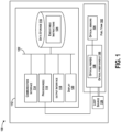
- the system 100 includes a fuel tank 102, a plurality of optical sensors 104 mounted inside the fuel tank 102, an optical fiber bundle 106 that has optical fibers 108 connected to each of the optical sensors 104 for guiding light to each of the optical sensors 104, and one or more processor(s) 110 connected to the optical fiber bundle 106 for receiving outputs of the optical sensors 104 indicative of respective pressures, and for determining a fuel level measurement of the fuel tank 102 based on the outputs of the optical sensors 104.
- the fuel tank 102 can be a single fuel tank with a single section, a single fuel tank with multiple sections, or multiple fuel tanks as well.
- the optical sensors 104 each include a sensor chip 140 and a diaphragm 142 that deflects when ambient pressure differs from a reference pressure of the sensor chip, as described in more detail with reference to Figure 4 below.
- the optical sensors 104 include dynamic photonic crystal optical pressure sensors.
- the optical fiber bundle 106 includes the optical fibers 108 that are used to carry light.
- the optical fibers 108 may be individually coated with plastic layers and contained in a protective tube. Different types of cable can be used, and arranged together within the optical fiber bundle 106.
- the optical fiber bundle 106 is arranged to enter the fuel tank 102 at one location and is positioned inside the fuel tank 102 and terminates with respective optical fibers 108 at respective positions of the optical sensors 104. Although Figure 1 shows the entire optical fiber bundle 106 positioned inside the fuel tank 102, a portion of the optical fiber bundle 106 may be positioned outside the fuel tank 102 to connect to the processor(s)110.
- the system 100 is also shown to preferably include a computing device 112 that has the processor(s) 110, and also a communication interface 114, data storage 116, an output interface 118, and a display 120 each connected to a communication bus 122.
- the computing device 112 may also include hardware to enable communication within the computing device 112 and between the computing device 112 and other devices (not shown).
- the hardware may include transmitters, receivers, and antennas, for example.
- the communication interface 114 may be a wireless interface and/or one or more wireline interfaces that allow for both short-range communication and long-range communication to one or more networks or to one or more remote devices.
- Such wireless interfaces may provide for communication under one or more wireless communication protocols, such as Very High Frequency (VHF) Data link (VDL), VDL Mode 2, Aircraft Communications Addressing and Reporting System (ACARS) digital communications over VHF radio and satellite communications (SATCOM), Bluetooth, WiFi (e.g., an institute of electrical and electronic engineers (IEEE) 802.11 protocol), Long-Term Evolution (LTE), cellular communications, near-field communication (NFC), and/or other wireless communication protocols.
- VHF Very High Frequency
- VDL Very High Frequency Data link
- ACARS Aircraft Communications Addressing and Reporting System
- SATCOM Aircraft Communications Addressing and Reporting System
- WiFi e.g., an institute of electrical and electronic engineers (IEEE) 802.11 protocol
- LTE Long-Term Evolution
- NFC near-field communication
- Such wireline interfaces may include aircraft data buses such as Aeronautical Radio, Incorporated (ARINC) 429, 629, or 664 based interfaces, Ethernet interface, a Universal Serial Bus (USB) interface, or similar interface to communicate via a wire, a twisted pair of wires, a coaxial cable, an optical link, a fiber-optic link, or other physical connection to a wireline network.
- ARINC Aeronautical Radio, Incorporated
- USB Universal Serial Bus
- the communication interface 114 may be configured to receive input data from one or more devices, and may also be configured to send output data to other devices.
- the processor(s) 110 may be a general-purpose processor or a special purpose processor (e.g., digital signal processors, application specific integrated circuits, etc.).
- the processor(s) 110 may receive inputs from the optical fiber bundle 106, and process the inputs to generate outputs that are stored in the data storage 116 and output to the display 120.
- the processor(s) 110 can be configured to execute the executable instructions 124 (e.g., computer-readable program instructions) that are stored in the data storage 116 and are executable to provide the functionality of the system 100 described herein.
- the output interface 118 outputs information to the display 120 or to other components as well.
- the output interface 118 may be similar to the communication interface 114 and can be a wireless interface (e.g., transmitter) or a wired interface as well.
- the system 100 may also include a light source 126 coupled or connected to the optical fiber bundle 106 for generating the light that is carried by the optical fiber(s) 108.
- the light source 126 can include a single light emitting diode (LED), or multiple LEDs, for example.
- the light source 126 can be connected to the optical fiber bundle 106 outside of the fuel tank 102.
- the system 100 may be included within a number of different vehicles, including aircraft, automobiles, or boats, for example.
- FIG 2 is a block diagram of an aircraft 130, according to the present invention.
- the aircraft 130 may include the system 100, although only a portion of the system 100 is shown in Figure 2 for simplicity.
- the aircraft 130 includes the fuel tank 102 positioned in one or more of a wing 132 and a fuselage 134 of the aircraft 130.
- the fuel tank 102 can be positioned entirely within the wing 132, or . can be positioned entirely within the fuselage 134.
- the fuel tank 102 can be positioned to have a portion within the wing 132 and a portion within the fuselage 134.
- FIG 3 illustrates an example of the wing 132 including the fuel tank 102.
- the fuel tank 102 is shown to be positioned in the wing 132 and to extend to a tip of the wing 132.
- the fuel tank 102 is also shown to be divided into multiple sections. Each section may include at least one optical sensor 104, for example. Alternatively the fuel tank 102 may not include multiple sections.
- components of the system 100 such as the light source 126 and the processor(s) 110 may be positioned elsewhere in the aircraft 130, or adjacent to the fuel tank 102 as well
- the processor(s) 110 can execute the executable instructions 124 stored in the data storage 116 to perform functions in real-time during flight of the aircraft 130. Such function can then occur with no or little delay to process additional data received from other sources or through manual input.
- the real time processing means that the processor(s) 110 perform the actions during flight of the aircraft 130.
- the real time processing may continually process information received from the optical sensors 104.
- the real time aspect includes the processor(s) 110 determining the fuel level measurement substantially immediately upon receiving new or updated outputs from the optical sensors 104.
- the reflected light is therefore a measure of a reflector separation, which is a measure of the ambient pressure. Intensity of the reflected light and a phase between the different reflections can provide a pressure measurement. Lookup tables can be provided with reference to the pressure that corresponds to the reflected light.
- the optical fiber bundle 106 and the optical sensors 104 can be positioned entirely into the fuel tank 102, and can be attached to an interior surface of the fuel tank 102 with an adhesive.
- a volume of the fuel is calculated and density of fuel utilized.
- a height of fuel in the fuel tank is first determined.
- Outputs of the optical sensors 104a-b can be used to determine the height.
- the diaphragm 142 of the optical sensors 104a-b deflects when ambient pressure differs from a reference pressure of the sensor chip 140, and this will occur when the fuel is at or above a level of the optical sensors 104a-b so as to contact the diaphragm 142.
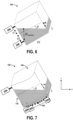
- the respective positions of the optical sensors 104a-b inside the fuel tank 102 may be represented by the height (H) above the bottom 162 of the fuel tank 102, and the processor(s) 110 determines the height (H) of fuel in the fuel tank 102 based on a ratio of a difference of pressures indicated by a first optical sensor 104a and a second optical sensor 104b and a specific gravity of fuel included in the fuel tank 102 when the tank is level.
- the processor(s) 110 determine the specific gravity of fuel included in the fuel tank 102 based on a temperature inside the fuel tank 102 and reference to a density/temperature empirical lookup table. Fuel density is not constant, and is based on a function of temperature.
- a type of fuel in the fuel tank 102 is known, and the type of fuel will have a known density at a specific temperature.
- Temperature sensors can be included in the fuel tank 102 and connected to the processor(s) 110, and then an emperical lookup table can be used to determine the density for the known type of fuel given the temperature of the fuel.
- a density/temperature curve can be selected, and then when the aircraft 130 is in flight, readings from the temperature sensors can be used in the lookup table to determine the density.
- the wing 132 deflects due to wind turbulence and other flight conditions. As a length of the wing 132 increases, an amount of deflection also increases. The deflection of the wing 132 can cause a change in the volume calculation above.
- the processor(s) 110 enables the processor(s) 110 to account for wing deflection and flight dynamics in the calculation of the fuel level measurement based on the measured pressure.
- the angle ( ⁇ ) can be determined from the roll of the fuel tank 102 or aircraft 130, and is provided by the flight control system 136. Thus, the flight control system 136 may output the angle ( ⁇ ) to the processor(s) 110. Once the height (H) is determined using Equation (3), then the volume calculation can be performed as described above. A similar calculation would be made for the aircraft with yaw and pitch inclinations.
- the processor(s) 110 can further receive information related to one or more of a roll, a pitch, and a yaw of the fuel tank 102, and determine the height (H) of fuel in the fuel tank 102 based on (i) a ratio of a difference of pressures indicated by a first optical sensor 104a and a second optical sensor 104b and a specific gravity of fuel included in the fuel tank 102 and (ii) the angle ( ⁇ ) of tilt of the fuel tank 102 determined from the information related to one or more of the roll, the pitch, and the yaw of the fuel tank 102.
- Each of the optical sensors 104a-n represented as p i ( x ) in the Equations above, provides a pressure output to calculate the height h i ( x ) at that x location. Due to a tilt of the aircraft 130 and the fuel tank 102, take cos ⁇ , and discretize and sum volumes of fuel using the measured pressure of each segment. Furthermore, due to the deformation in the top 160 and the bottom162, the variations of volume of the fuel tank 102 can be taken into account using outputs from all of the optical sensors 104an.
- the processor(s) 110 may determine the height (H) of fuel in the fuel tank 102 at a position of each of the optical sensors 104a-n based on the respective pressures and on an angle of tilt of the fuel tank 102, and determine the fuel level measurement of the fuel tank 102 based on a sum of a volume of fuel as determined due to the height (H) for each of the optical sensors 104a-n.
- Figure 7 illustrates the optical sensor 104a positioned on the side 170 of the fuel tank and the optical sensors 104b-n positioned on the bottom 162 of the fuel tank 102
- many other arrangements of optical sensors on or in the fuel tank 102 can be provided.
- the fuel tank 102 is installed in the wing 132 of the aircraft 130, as the wing 132 deflects more, and is more flexible, use of more optical sensors can provide higher accuracy in the fuel level measurement.
- the wing 132 is a rigid wing 132
- less optical sensors may be needed for high accuracy of the fuel level measurement.
- shorter wings may use less optical sensors than longer wings. Any number of optical sensors may be used depending on a size and shape of the wing.
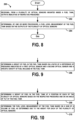
- Figure 8 shows a flowchart of a method 200 for determining a fuel level measurement of the fuel tank 102, according to the present invention.
- Method 200 shown in Figure 8 can be used with the system 100 shown in Figure 1 and the aircraft 130 shown in Figure 2 .
- devices or systems may be used or configured to perform logical functions presented in Figure 8 .
- Components of the devices and/or systems may be configured to perform the functions such that the components are actually configured and structured (with hardware and/or software) to enable such performance.
- Components of the devices and/or systems may be arranged to be adapted to, capable of, or suited for performing the functions, such as when operated in a specific manner.
- Method 200 may include one or more operations, functions, or actions as illustrated by one or more of blocks 202 and 204. Although the blocks are illustrated in a sequential order, these blocks may also be performed in parallel, and/or in a different order than those described herein. Also, the various blocks may be combined into fewer blocks, divided into additional blocks, and/or removed
- each block may represent a module, a segment, or a portion of program code, which includes one or more instructions executable by a processor for implementing specific logical functions or steps in the process.
- the program code may be stored on any type of computer readable medium or data storage, for example, such as a storage device including a disk or hard drive. Further, the program code can be encoded on a computer-readable storage media in a machine-readable format, or on other non-transitory media or articles of manufacture.
- the computer readable medium may include non-transitory computer readable medium or memory, for example, such as computer-readable media that stores data for short periods of time like register memory, processor cache and Random Access Memory (RAM).
- the computer readable medium may also include non-transitory media, such as secondary or persistent long term storage, like read only memory (ROM), optical or magnetic disks, compact-disc read only memory (CD-ROM), for example.
- the computer readable media may also be any other volatile or non-volatile storage systems.
- the computer readable medium may be considered a tangible computer readable storage medium, for example.
- each block in Figure 8 may represent circuitry that is wired to perform the specific logical functions in the process.
- Alternative implementations are included within the scope of the examples of the present disclosure in which functions may be executed out of order from that shown or discussed, including substantially concurrent or in reverse order, depending on the functionality involved, as would be understood by those reasonably skilled in the art.
- the method 200 includes receiving, from a plurality of optical sensors 104 mounted inside the fuel tank 102, outputs indicative of respective pressures.
- the plurality of optical sensors 104 each include the sensor chip 140 and the diaphragm 142 that deflects when ambient pressure differs from a reference pressure of the sensor chip 140.
- the method 200 includes determining, by the processor(S) 110, a fuel level measurement of the fuel tank 102 based on the outputs of the plurality of optical sensors 104.
- the determination of the fuel level measurement may be made using Equations (1)-(4) above.
- FIG. 10 shows a flowchart of an example method for use with the method 200, according to the present invention.
- functions include determining a height of fuel in the fuel tank 102 at a position of each of the plurality of optical sensors 104 based on the respective pressures and on an angle of tilt of the fuel tank 102, and at block 210, functions include determining the fuel level measurement of the fuel tank 102 based on a sum of a volume of fuel as determined due to the height for each of the plurality of optical sensors 104.
- the system 100 described can use the optical sensors 104 to replace current fuels quantity indication system (FQIS) with new intrinsically EMI safe system that requires no metal in the fuel tank 102.
- FQIS current fuels quantity indication system
- metal wires are not needed in the fuel tank 102 and there is no need for redundant supports. It is desired to eliminate use of copper wiring in the fuel tank 102, and use of the optical fiber bundle 106 can do so. This decreases system weight and manufacturing time.
- the example applications of photonic crystal pressure sensors for aircraft fuel level measurement enable the fuel level measurement to be calculated when experiencing wing deflections and flight dynamics.
- Example benefits of use of the system 100 include high accuracy pressure measurements that satisfy no sources of ignition requirement as it uses a low power light beam completely enclosed, no interaction with fuel, and no sources of ignition in the fuel tank 102.
- the system 100 has a potential for a large reduction in weight from existing fuel gauging systems since the optical sensors 104 are lightweight as compared to existing capacitive sensors.
- the system 100 can be used in areas such as fuel tanks, where the environment due to conditions such as heat or safety concerns can lead to difficult engineering challenges.
Landscapes
- Physics & Mathematics (AREA)
- Fluid Mechanics (AREA)
- General Physics & Mathematics (AREA)
- Electromagnetism (AREA)
- Thermal Sciences (AREA)
- Engineering & Computer Science (AREA)
- Aviation & Aerospace Engineering (AREA)
- Measurement Of Levels Of Liquids Or Fluent Solid Materials (AREA)
- Measuring Fluid Pressure (AREA)
Claims (15)
- System (100), umfassend:einen Kraftstofftank (102);eine Vielzahl von optischen Sensoren (104), die innerhalb des Kraftstofftanks (102) montiert sind, wobei die Vielzahl von optischen Sensoren (104) jeweils einen Sensorchip (140) und eine Membran (142) umfassen, die sich biegt, wenn der Umgebungsdruck von einem Referenzdruck des Sensorchips (140) abweicht;ein optisches Faserbündel (106), das optische Fasern (108) umfasst, wobei eine einzelne optische Faser (108) des optischen Faserbündels (106) mit jedem der Vielzahl von optischen Sensoren (104) verbunden ist, um Licht zu jedem der optischen Sensoren (104) zu leiten; undeinen oder mehrere Prozessoren (110), die mit dem optischen Faserbündel (106) verbunden sind, um Ausgaben der Vielzahl von optischen Sensoren (104) zu empfangen, die jeweilige Drücke anzeigen, und um auf der Grundlage der Ausgaben der Vielzahl von optischen Sensoren (104) eine Kraftstoffstandmessung des Kraftstofftanks (102) zu bestimmen.
- System (100) nach Anspruch 1, wobei der Kraftstofftank (102) eine Oberseite (160), eine Unterseite (162) und Seiten (164-170) aufweist und wobei jeweilige Sensoren der Vielzahl von optischen Sensoren (104) zumindest an einer Seite (164-170) und am Boden (162) positioniert sind, und wobei sich die Ausgaben der Vielzahl von optischen Sensoren (104) verhältnismäßig ändern, während die Vielzahl von optischen Sensoren (104) im Kraftstofftank (102) in Kraftstoff eingetaucht werden.
- System (100) nach Anspruch 1 oder 2, wobei das optische Faserbündel (106) an einer Stelle in den Kraftstofftank (102) eintritt und innerhalb des Kraftstofftanks (102) positioniert ist und mit entsprechenden optischen Fasern (108) an jeweiligen Positionen der Vielzahl von optischen Sensoren (104) endet.
- System (100) nach einem der Ansprüche 1 bis 3, wobei die Ausgaben der Vielzahl von optischen Sensoren (104) reflektiertes Licht von jeweiligen Membranen (142) umfassen und wobei der eine oder die mehreren Prozessoren (110) einen entsprechenden Druck auf der Grundlage des reflektierten Lichts bestimmen.
- System (100) nach einem der Ansprüche 1 bis 4, wobei die Kraftstoffstandmessung ein Kraftstoffvolumen im Kraftstofftank (102) umfasst und die Vielzahl von optischen Sensoren (104) ferner Ausgaben zur Bestimmung einer Temperatur im Inneren des Kraftstofftanks (102) bereitstellen.
- System (100) nach einem der Ansprüche 1 bis 5, das ferner eine Lichtquelle (126) umfasst, die mit dem optischen Faserbündel (106) gekoppelt ist, um das Licht zu erzeugen.
- System (100) nach einem der Ansprüche 1 bis 6, wobei die jeweiligen Positionen der Vielzahl von optischen Sensoren (104) innerhalb des Kraftstofftanks (102) durch eine Höhe über einem Boden des Kraftstofftanks (102) dargestellt sind, und
wobei der eine oder die mehreren Prozessoren (110) eine Kraftstoffhöhe im Kraftstofftank (102) auf der Grundlage eines Verhältnisses einer Differenz der von einem ersten optischen Sensor (104a) und einem zweiten optischen Sensor (104b) angezeigten Drücke und einer relativen Dichte des im Kraftstofftank (102) enthaltenen Kraftstoffs. - System (100) nach einem der Ansprüche 1 bis 7, wobei der eine oder die mehreren Prozessoren (110) die relative Dichte des im Kraftstofftank (102) enthaltenen Kraftstoffs auf der Grundlage einer Temperatur im Inneren des Kraftstofftanks (102) und einem Verweis auf ein Massendichte-/Temperaturdiagramm bestimmen.
- System (100) nach einem der Ansprüche 1 bis 7, wobei der eine oder die mehreren Prozessoren (110) die relative Dichte des im Kraftstofftank (102) enthaltenen Kraftstoffs basierend auf Folgenden bestimmen: (i) einer Differenz zwischen den Ausgaben von zwei Sensoren der Vielzahl von optischen Sensoren (104) zur Bestimmung einer Gewichtsdifferenz des Kraftstoffs und (ii) einem bekannten Abstand zwischen den beiden Sensoren zur Berechnung eines Gewichts pro Volumeneinheit des Kraftstoffs.
- System (100) nach einem der Ansprüche 1 bis 9, wobei der eine oder die mehreren Prozessoren (110) ferner Informationen in Bezug auf ein Rollen, Nicken und/oder Gieren des Kraftstofftanks (102) empfangen, und
wobei der eine oder die mehreren Prozessoren (110) eine Kraftstoffhöhe im Kraftstofftank (102) basierend auf Folgenden bestimmen: (i) einem Verhältnis einer Differenz der von einem ersten optischen Sensor (104a) und einem zweiten optischen Sensor (104b) angezeigten Drücke und einer relativen Dichte des im Kraftstofftank (102) enthaltenen Kraftstoffs und (ii) einem Neigungswinkel des Kraftstofftanks (102), der aus den Informationen in Bezug auf ein Rollen, Nicken und/oder Gieren des Kraftstofftanks (102) bestimmt wird. - System (100) nach einem der Ansprüche 1 bis 9, wobei der eine oder die mehreren Prozessoren (110) eine Kraftstoffhöhe im Kraftstofftank (102) an einer Position jedes der Vielzahl von optischen Sensoren (104) auf der Grundlage der jeweiligen Drücke und eines Neigungswinkels des Kraftstofftanks (102) bestimmen, und
wobei der eine oder die mehreren Prozessoren (110) die Kraftstoffstandmessung des Kraftstofftanks (102) auf der Grundlage einer Summe eines Kraftstoffvolumens bestimmen, das aufgrund der Höhe für jeden der Vielzahl von optischen Sensoren (104) bestimmt wurde. - Flugzeug (130), das ein System nach einem der vorhergehenden Ansprüche umfasst.
- Verfahren (200) zum Bestimmen einer Kraftstoffstandmessung eines Kraftstofftanks (102), umfassend:Leiten von Licht zu jedem einer Vielzahl von optischen Sensoren (104) unter Verwendung eines optischen Faserbündels (106), das optische Fasern (108) umfasst und bei dem eine einzelne optische Faser (108) mit jedem der Vielzahl von optischen Sensoren (104) verbunden ist;Empfangen (202) von Ausgaben, die jeweilige Drücke anzeigen, aus der Vielzahl von innerhalb eines Kraftstofftanks (102) montierten optischen Sensoren (104), wobei die Vielzahl von optischen Sensoren (104) jeweils einen Sensorchip (140) und eine Membran (142) umfassen, die sich biegt, wenn der Umgebungsdruck von einem Referenzdruck des Sensorchips (140) abweicht; undauf der Grundlage der Ausgaben der Vielzahl von optischen Sensoren (104) Bestimmen (204) einer Kraftstoffstandmessung des Kraftstofftanks (102) durch einen oder mehrere Prozessoren (110), die mit dem optischen Faserbündel (106) verbunden sind, um Ausgaben der Vielzahl von optischen Sensoren (104) zu empfangen, die jeweilige Drücke anzeigen (102).
- Verfahren nach Anspruch 13, wobei die jeweiligen Positionen der Vielzahl von optischen Sensoren (104) innerhalb des Kraftstofftanks (102) durch eine Höhe über einem Boden (162) des Kraftstofftanks (102) dargestellt sind, und wobei das Verfahren ferner Folgendes umfasst:
Bestimmen (206) einer Kraftstoffhöhe im Kraftstofftank (102) auf der Grundlage eines Verhältnisses einer Differenz der von einem ersten optischen Sensor (104a) und einem zweiten optischen Sensor (104b) angezeigten Drücke und einer relativen Dichte des in dem Kraftstofftank (102) enthaltenen Kraftstoffs. - Verfahren nach Anspruch 13, ferner umfassend:Bestimmen (208) einer Kraftstoffhöhe im Kraftstofftank (102) an einer Position jedes der Vielzahl von optischen Sensoren (104) auf der Grundlage der jeweiligen Drücke und eines Neigungswinkels des Kraftstofftanks (102); undBestimmen (210) der Kraftstoffstandmessung des Kraftstofftanks (102) auf der Grundlage einer Summe eines Kraftstoffvolumens, das aufgrund der Höhe für jeden der Vielzahl von optischen Sensoren (104) bestimmt wurde.
Applications Claiming Priority (1)
| Application Number | Priority Date | Filing Date | Title |
|---|---|---|---|
| US15/243,062 US10126158B2 (en) | 2016-08-22 | 2016-08-22 | Systems and methods for determining a fuel level measurement of a fuel tank using optical sensor |
Publications (2)
| Publication Number | Publication Date |
|---|---|
| EP3287753A1 EP3287753A1 (de) | 2018-02-28 |
| EP3287753B1 true EP3287753B1 (de) | 2023-12-13 |
Family
ID=59383506
Family Applications (1)
| Application Number | Title | Priority Date | Filing Date |
|---|---|---|---|
| EP17182425.3A Active EP3287753B1 (de) | 2016-08-22 | 2017-07-20 | Systeme und verfahren zur bestimmung einer kraftstoffffüllstandsmessung eines kraftstofftanks mit optischen sensoren |
Country Status (6)
| Country | Link |
|---|---|
| US (2) | US10126158B2 (de) |
| EP (1) | EP3287753B1 (de) |
| JP (1) | JP2018031772A (de) |
| CN (1) | CN107764367B (de) |
| CA (1) | CA2972458C (de) |
| RU (1) | RU2746416C2 (de) |
Families Citing this family (12)
| Publication number | Priority date | Publication date | Assignee | Title |
|---|---|---|---|---|
| US10126158B2 (en) | 2016-08-22 | 2018-11-13 | The Boeing Company | Systems and methods for determining a fuel level measurement of a fuel tank using optical sensor |
| CN108332780B (zh) * | 2017-01-10 | 2020-11-10 | 派克汉尼芬公司 | 光学供电的传感器校准数据存储模块 |
| US10641645B2 (en) * | 2017-09-28 | 2020-05-05 | Simmonds Precision Products, Inc. | Integral fluid measurement system |
| US12187458B2 (en) * | 2018-11-08 | 2025-01-07 | The Boeing Company | Fuel tank testing system |
| CN110987118B (zh) * | 2019-12-26 | 2020-09-22 | 长沙华时捷环保科技发展股份有限公司 | 一种测量熔融硫磺液位的方法 |
| CN111735517B (zh) * | 2020-07-13 | 2023-10-20 | 浙江聚励云机械科技有限公司 | 液位测量方法 |
| EP3961163B1 (de) | 2020-08-31 | 2024-11-06 | Simmonds Precision Products, Inc. | Fluidmengensensorsystem |
| US12339153B2 (en) * | 2022-02-09 | 2025-06-24 | Simmonds Precision Products, Inc. | Optical fabry-perot based liquid level sensors |
| GB2627766A (en) * | 2023-02-28 | 2024-09-04 | Airbus Operations Ltd | Monitoring an aircraft fluid storage tank assembly |
| US12459662B2 (en) | 2023-04-26 | 2025-11-04 | Rockwell Collins, Inc. | Enhanced vehicle fuel quantity indication system |
| GB2630358A (en) * | 2023-05-25 | 2024-11-27 | Airbus Operations Ltd | Fuel tank monitoring system |
| US20250314194A1 (en) * | 2024-04-09 | 2025-10-09 | Pratt & Whitney Canada Corp. | Heat exchanger cooling assembly for an aircraft propulsion system |
Citations (4)
| Publication number | Priority date | Publication date | Assignee | Title |
|---|---|---|---|---|
| US20040031326A1 (en) * | 2002-06-11 | 2004-02-19 | Thomas Lenzing | Fiber-optic pressure sensor |
| US20140168659A1 (en) * | 2010-12-28 | 2014-06-19 | The Secretary, Department Of Atomic Energy, Govt. Of India | Micromachined metal diaphragm based fabry-perot fiberoptic sensor system and data processing involving the same |
| US20150100253A1 (en) * | 2013-10-09 | 2015-04-09 | Parker-Hannifin Corporation | Aircraft fluid gauging techniques using pressure measurements and optical sensors |
| EP2966443A1 (de) * | 2014-07-10 | 2016-01-13 | Airbus Operations Limited | Analyse des inhalts eines treibstofftanks |
Family Cites Families (22)
| Publication number | Priority date | Publication date | Assignee | Title |
|---|---|---|---|---|
| JPS62179611A (ja) * | 1986-02-03 | 1987-08-06 | Yokogawa Electric Corp | 飛行体の燃料重量残量測定装置 |
| CN2052893U (zh) * | 1989-07-29 | 1990-02-14 | 辽河石油勘探局油气管理处 | 光纤油罐储量计量装置 |
| US5138559A (en) * | 1989-08-28 | 1992-08-11 | The Boeing Company | System and method for measuring liquid mass quantity |
| US5026984A (en) | 1990-01-16 | 1991-06-25 | Sperry Marine, Inc. | Methods for sensing temperature, pressure and liquid level and variable ratio fiber optic coupler sensors therefor |
| JP3159474B2 (ja) * | 1991-06-20 | 2001-04-23 | 国際計測器株式会社 | タイヤホイールのバランスウェイト装着装置 |
| JPH06331416A (ja) * | 1993-05-27 | 1994-12-02 | Yamatake Honeywell Co Ltd | 液体の状態量検出装置 |
| JP2000292287A (ja) * | 1999-04-12 | 2000-10-20 | Tokimec Inc | 圧力温度測定装置 |
| JP2001318016A (ja) * | 2000-05-11 | 2001-11-16 | Yokogawa Electric Corp | ダイアフラムシール型差圧測定装置 |
| US6282953B1 (en) * | 2000-05-12 | 2001-09-04 | Eaton Corporation | Solid state fuel level sensing |
| IT1317767B1 (it) * | 2000-05-31 | 2003-07-15 | Gigi Molina Brevetti Plastici | Apparecchio per controllare il livello di un liquido |
| US6502042B1 (en) * | 2000-10-26 | 2002-12-31 | Bfgoodrich Aerospace Fuel And Utility Systems | Fault tolerant liquid measurement system using multiple-model state estimators |
| US20030010115A1 (en) * | 2001-07-16 | 2003-01-16 | Kelley Ronald J. | Means for measuring the liquid level in a reservoir for a fuel cell |
| US7669473B2 (en) * | 2005-05-11 | 2010-03-02 | Innovative Solutions & Support, Inc. | Pressure-based aircraft fuel capacity monitoring system and method |
| FR2906027B1 (fr) * | 2006-09-20 | 2009-02-20 | Airbus Sas | Dispositif de mesure multicapteur pour sonde de jaugeage embarquee |
| US9020767B2 (en) * | 2011-11-21 | 2015-04-28 | The Boeing Company | Wireless fuel monitoring system |
| FR2991485B1 (fr) * | 2012-06-05 | 2015-08-14 | Airbus Operations Sas | Procede et dispositif d'estimation automatique d'une degradation en consommation et en trainee d'un aeronef. |
| GB2503466B (en) | 2012-06-27 | 2017-04-19 | Oxsensis Ltd | Optical sensor |
| GB201220658D0 (en) | 2012-11-16 | 2013-01-02 | Airbus Operations Ltd | Time domain reflectometry fuel gauge |
| GB2520721A (en) * | 2013-11-29 | 2015-06-03 | Airbus Operations Ltd | Fuel surface height measurement |
| RU2564683C1 (ru) * | 2014-03-27 | 2015-10-10 | Татьяна Ивановна Мурашкина | Волоконно-оптический уровнемер и способ его изготовления |
| US10053269B2 (en) * | 2015-02-09 | 2018-08-21 | The Boeing Company | Multi-functional fiber optic fuel sensor system having a photonic membrane |
| US10126158B2 (en) | 2016-08-22 | 2018-11-13 | The Boeing Company | Systems and methods for determining a fuel level measurement of a fuel tank using optical sensor |
-
2016
- 2016-08-22 US US15/243,062 patent/US10126158B2/en active Active
-
2017
- 2017-06-28 RU RU2017122811A patent/RU2746416C2/ru active
- 2017-06-30 CA CA2972458A patent/CA2972458C/en active Active
- 2017-07-03 JP JP2017130147A patent/JP2018031772A/ja active Pending
- 2017-07-20 EP EP17182425.3A patent/EP3287753B1/de active Active
- 2017-08-15 CN CN201710697154.4A patent/CN107764367B/zh active Active
-
2018
- 2018-10-10 US US16/155,999 patent/US10648846B2/en active Active
Patent Citations (4)
| Publication number | Priority date | Publication date | Assignee | Title |
|---|---|---|---|---|
| US20040031326A1 (en) * | 2002-06-11 | 2004-02-19 | Thomas Lenzing | Fiber-optic pressure sensor |
| US20140168659A1 (en) * | 2010-12-28 | 2014-06-19 | The Secretary, Department Of Atomic Energy, Govt. Of India | Micromachined metal diaphragm based fabry-perot fiberoptic sensor system and data processing involving the same |
| US20150100253A1 (en) * | 2013-10-09 | 2015-04-09 | Parker-Hannifin Corporation | Aircraft fluid gauging techniques using pressure measurements and optical sensors |
| EP2966443A1 (de) * | 2014-07-10 | 2016-01-13 | Airbus Operations Limited | Analyse des inhalts eines treibstofftanks |
Also Published As
| Publication number | Publication date |
|---|---|
| US10648846B2 (en) | 2020-05-12 |
| RU2017122811A (ru) | 2018-12-28 |
| US20190049280A1 (en) | 2019-02-14 |
| CN107764367B (zh) | 2020-11-27 |
| CN107764367A (zh) | 2018-03-06 |
| RU2746416C2 (ru) | 2021-04-13 |
| CA2972458A1 (en) | 2018-02-22 |
| JP2018031772A (ja) | 2018-03-01 |
| CA2972458C (en) | 2021-11-09 |
| US10126158B2 (en) | 2018-11-13 |
| EP3287753A1 (de) | 2018-02-28 |
| RU2017122811A3 (de) | 2020-09-24 |
| US20180052029A1 (en) | 2018-02-22 |
Similar Documents
| Publication | Publication Date | Title |
|---|---|---|
| EP3287753B1 (de) | Systeme und verfahren zur bestimmung einer kraftstoffffüllstandsmessung eines kraftstofftanks mit optischen sensoren | |
| US11174036B2 (en) | Methods for installation of sensors and determining a fuel level measurement of fuel using a fuel level measurement system | |
| US11988539B2 (en) | Aircraft fluid gauging techniques using pressure measurements and optical sensors | |
| EP3054272B1 (de) | Multifunktionales faseroptisches brennstoffsensorsystem mit photonischer membran | |
| EP3301412B1 (de) | Wellengeführtes radarfüllstandsmesssystem mit zwei übertragungsleitungssonden zur kompensation der dielektrizitätskonstante | |
| EP3482216A1 (de) | Systeme und verfahren für optische luftdaten | |
| CN104963980A (zh) | 减震器和确定减震器内液位的方法 | |
| EP3301456B1 (de) | Montieren eines lasersende-empfängers an einem flugzeug | |
| EP3367076B1 (de) | Systeme und verfahren zur bestimmung der flugzeugmasse | |
| KR102589209B1 (ko) | 페이즈드 어레이 안테나에 대한 전자기장 패턴 | |
| EP3285090B1 (de) | Vermessung von wolkenmetriken mit einem quasi-optischen radar und einem lidar | |
| WO2010102098A1 (en) | Fiber cable distortion detection system and method | |
| EP3547548B1 (de) | Schnittstellensysteme und -verfahren zur fluidmessung | |
| EP4372387A1 (de) | Optisches geschwindigkeitsdetektionssystem mit dualem frequenzverschiebungslaser für fahrzeuge | |
| CN103868522A (zh) | 无线电高度表的测高精度测试装置 | |
| US12332105B2 (en) | Device and method for measuring the fill level in a tank for a vehicle, tank provided therewith, vehicle, and production method | |
| Mathur | Fiber optics & aviation: integration | |
| EP4369001B1 (de) | Lasersystem zur geschwindigkeitserfassung eines fahrzeugs | |
| EP4451009A1 (de) | Aom-frequenzschiebertestvorrichtung | |
| EP4485000A1 (de) | Verfahren und strahlungsdetektor für kraftfahrzeugradartests | |
| Richards et al. | Fiber Optic Wing Shape Sensing on NASA's Ikhana UAV | |
| US20250155317A1 (en) | Wind Tunnel Turbulent Airflow Laser Sensor System | |
| JP4500299B2 (ja) | 電波高度計 | |
| CN116930552A (zh) | 一种加速度传感探头、加速度传感系统及其测量方法 |
Legal Events
| Date | Code | Title | Description |
|---|---|---|---|
| PUAI | Public reference made under article 153(3) epc to a published international application that has entered the european phase |
Free format text: ORIGINAL CODE: 0009012 |
|
| STAA | Information on the status of an ep patent application or granted ep patent |
Free format text: STATUS: REQUEST FOR EXAMINATION WAS MADE |
|
| 17P | Request for examination filed |
Effective date: 20170720 |
|
| AK | Designated contracting states |
Kind code of ref document: A1 Designated state(s): AL AT BE BG CH CY CZ DE DK EE ES FI FR GB GR HR HU IE IS IT LI LT LU LV MC MK MT NL NO PL PT RO RS SE SI SK SM TR |
|
| AX | Request for extension of the european patent |
Extension state: BA ME |
|
| STAA | Information on the status of an ep patent application or granted ep patent |
Free format text: STATUS: EXAMINATION IS IN PROGRESS |
|
| 17Q | First examination report despatched |
Effective date: 20210706 |
|
| RAP3 | Party data changed (applicant data changed or rights of an application transferred) |
Owner name: THE BOEING COMPANY |
|
| GRAP | Despatch of communication of intention to grant a patent |
Free format text: ORIGINAL CODE: EPIDOSNIGR1 |
|
| STAA | Information on the status of an ep patent application or granted ep patent |
Free format text: STATUS: GRANT OF PATENT IS INTENDED |
|
| INTG | Intention to grant announced |
Effective date: 20230704 |
|
| GRAS | Grant fee paid |
Free format text: ORIGINAL CODE: EPIDOSNIGR3 |
|
| GRAA | (expected) grant |
Free format text: ORIGINAL CODE: 0009210 |
|
| STAA | Information on the status of an ep patent application or granted ep patent |
Free format text: STATUS: THE PATENT HAS BEEN GRANTED |
|
| AK | Designated contracting states |
Kind code of ref document: B1 Designated state(s): AL AT BE BG CH CY CZ DE DK EE ES FI FR GB GR HR HU IE IS IT LI LT LU LV MC MK MT NL NO PL PT RO RS SE SI SK SM TR |
|
| REG | Reference to a national code |
Ref country code: GB Ref legal event code: FG4D |
|
| REG | Reference to a national code |
Ref country code: CH Ref legal event code: EP |
|
| REG | Reference to a national code |
Ref country code: DE Ref legal event code: R096 Ref document number: 602017077419 Country of ref document: DE |
|
| REG | Reference to a national code |
Ref country code: IE Ref legal event code: FG4D |
|
| P01 | Opt-out of the competence of the unified patent court (upc) registered |
Effective date: 20231206 |
|
| PG25 | Lapsed in a contracting state [announced via postgrant information from national office to epo] |
Ref country code: GR Free format text: LAPSE BECAUSE OF FAILURE TO SUBMIT A TRANSLATION OF THE DESCRIPTION OR TO PAY THE FEE WITHIN THE PRESCRIBED TIME-LIMIT Effective date: 20240314 |
|
| REG | Reference to a national code |
Ref country code: LT Ref legal event code: MG9D |
|
| PG25 | Lapsed in a contracting state [announced via postgrant information from national office to epo] |
Ref country code: LT Free format text: LAPSE BECAUSE OF FAILURE TO SUBMIT A TRANSLATION OF THE DESCRIPTION OR TO PAY THE FEE WITHIN THE PRESCRIBED TIME-LIMIT Effective date: 20231213 |
|
| REG | Reference to a national code |
Ref country code: NL Ref legal event code: MP Effective date: 20231213 |
|
| PG25 | Lapsed in a contracting state [announced via postgrant information from national office to epo] |
Ref country code: ES Free format text: LAPSE BECAUSE OF FAILURE TO SUBMIT A TRANSLATION OF THE DESCRIPTION OR TO PAY THE FEE WITHIN THE PRESCRIBED TIME-LIMIT Effective date: 20231213 |
|
| PG25 | Lapsed in a contracting state [announced via postgrant information from national office to epo] |
Ref country code: LT Free format text: LAPSE BECAUSE OF FAILURE TO SUBMIT A TRANSLATION OF THE DESCRIPTION OR TO PAY THE FEE WITHIN THE PRESCRIBED TIME-LIMIT Effective date: 20231213 Ref country code: GR Free format text: LAPSE BECAUSE OF FAILURE TO SUBMIT A TRANSLATION OF THE DESCRIPTION OR TO PAY THE FEE WITHIN THE PRESCRIBED TIME-LIMIT Effective date: 20240314 Ref country code: ES Free format text: LAPSE BECAUSE OF FAILURE TO SUBMIT A TRANSLATION OF THE DESCRIPTION OR TO PAY THE FEE WITHIN THE PRESCRIBED TIME-LIMIT Effective date: 20231213 Ref country code: BG Free format text: LAPSE BECAUSE OF FAILURE TO SUBMIT A TRANSLATION OF THE DESCRIPTION OR TO PAY THE FEE WITHIN THE PRESCRIBED TIME-LIMIT Effective date: 20240313 |
|
| REG | Reference to a national code |
Ref country code: AT Ref legal event code: MK05 Ref document number: 1640796 Country of ref document: AT Kind code of ref document: T Effective date: 20231213 |
|
| PG25 | Lapsed in a contracting state [announced via postgrant information from national office to epo] |
Ref country code: NL Free format text: LAPSE BECAUSE OF FAILURE TO SUBMIT A TRANSLATION OF THE DESCRIPTION OR TO PAY THE FEE WITHIN THE PRESCRIBED TIME-LIMIT Effective date: 20231213 |
|
| PG25 | Lapsed in a contracting state [announced via postgrant information from national office to epo] |
Ref country code: SE Free format text: LAPSE BECAUSE OF FAILURE TO SUBMIT A TRANSLATION OF THE DESCRIPTION OR TO PAY THE FEE WITHIN THE PRESCRIBED TIME-LIMIT Effective date: 20231213 Ref country code: RS Free format text: LAPSE BECAUSE OF FAILURE TO SUBMIT A TRANSLATION OF THE DESCRIPTION OR TO PAY THE FEE WITHIN THE PRESCRIBED TIME-LIMIT Effective date: 20231213 Ref country code: NO Free format text: LAPSE BECAUSE OF FAILURE TO SUBMIT A TRANSLATION OF THE DESCRIPTION OR TO PAY THE FEE WITHIN THE PRESCRIBED TIME-LIMIT Effective date: 20240313 Ref country code: NL Free format text: LAPSE BECAUSE OF FAILURE TO SUBMIT A TRANSLATION OF THE DESCRIPTION OR TO PAY THE FEE WITHIN THE PRESCRIBED TIME-LIMIT Effective date: 20231213 Ref country code: LV Free format text: LAPSE BECAUSE OF FAILURE TO SUBMIT A TRANSLATION OF THE DESCRIPTION OR TO PAY THE FEE WITHIN THE PRESCRIBED TIME-LIMIT Effective date: 20231213 Ref country code: HR Free format text: LAPSE BECAUSE OF FAILURE TO SUBMIT A TRANSLATION OF THE DESCRIPTION OR TO PAY THE FEE WITHIN THE PRESCRIBED TIME-LIMIT Effective date: 20231213 |
|
| PG25 | Lapsed in a contracting state [announced via postgrant information from national office to epo] |
Ref country code: IS Free format text: LAPSE BECAUSE OF FAILURE TO SUBMIT A TRANSLATION OF THE DESCRIPTION OR TO PAY THE FEE WITHIN THE PRESCRIBED TIME-LIMIT Effective date: 20240413 |
|
| PG25 | Lapsed in a contracting state [announced via postgrant information from national office to epo] |
Ref country code: CZ Free format text: LAPSE BECAUSE OF FAILURE TO SUBMIT A TRANSLATION OF THE DESCRIPTION OR TO PAY THE FEE WITHIN THE PRESCRIBED TIME-LIMIT Effective date: 20231213 Ref country code: AT Free format text: LAPSE BECAUSE OF FAILURE TO SUBMIT A TRANSLATION OF THE DESCRIPTION OR TO PAY THE FEE WITHIN THE PRESCRIBED TIME-LIMIT Effective date: 20231213 |
|
| PG25 | Lapsed in a contracting state [announced via postgrant information from national office to epo] |
Ref country code: SK Free format text: LAPSE BECAUSE OF FAILURE TO SUBMIT A TRANSLATION OF THE DESCRIPTION OR TO PAY THE FEE WITHIN THE PRESCRIBED TIME-LIMIT Effective date: 20231213 |
|
| PG25 | Lapsed in a contracting state [announced via postgrant information from national office to epo] |
Ref country code: SM Free format text: LAPSE BECAUSE OF FAILURE TO SUBMIT A TRANSLATION OF THE DESCRIPTION OR TO PAY THE FEE WITHIN THE PRESCRIBED TIME-LIMIT Effective date: 20231213 Ref country code: SK Free format text: LAPSE BECAUSE OF FAILURE TO SUBMIT A TRANSLATION OF THE DESCRIPTION OR TO PAY THE FEE WITHIN THE PRESCRIBED TIME-LIMIT Effective date: 20231213 Ref country code: RO Free format text: LAPSE BECAUSE OF FAILURE TO SUBMIT A TRANSLATION OF THE DESCRIPTION OR TO PAY THE FEE WITHIN THE PRESCRIBED TIME-LIMIT Effective date: 20231213 Ref country code: IT Free format text: LAPSE BECAUSE OF FAILURE TO SUBMIT A TRANSLATION OF THE DESCRIPTION OR TO PAY THE FEE WITHIN THE PRESCRIBED TIME-LIMIT Effective date: 20231213 Ref country code: IS Free format text: LAPSE BECAUSE OF FAILURE TO SUBMIT A TRANSLATION OF THE DESCRIPTION OR TO PAY THE FEE WITHIN THE PRESCRIBED TIME-LIMIT Effective date: 20240413 Ref country code: EE Free format text: LAPSE BECAUSE OF FAILURE TO SUBMIT A TRANSLATION OF THE DESCRIPTION OR TO PAY THE FEE WITHIN THE PRESCRIBED TIME-LIMIT Effective date: 20231213 Ref country code: CZ Free format text: LAPSE BECAUSE OF FAILURE TO SUBMIT A TRANSLATION OF THE DESCRIPTION OR TO PAY THE FEE WITHIN THE PRESCRIBED TIME-LIMIT Effective date: 20231213 Ref country code: AT Free format text: LAPSE BECAUSE OF FAILURE TO SUBMIT A TRANSLATION OF THE DESCRIPTION OR TO PAY THE FEE WITHIN THE PRESCRIBED TIME-LIMIT Effective date: 20231213 |
|
| PG25 | Lapsed in a contracting state [announced via postgrant information from national office to epo] |
Ref country code: PT Free format text: LAPSE BECAUSE OF FAILURE TO SUBMIT A TRANSLATION OF THE DESCRIPTION OR TO PAY THE FEE WITHIN THE PRESCRIBED TIME-LIMIT Effective date: 20240415 Ref country code: PL Free format text: LAPSE BECAUSE OF FAILURE TO SUBMIT A TRANSLATION OF THE DESCRIPTION OR TO PAY THE FEE WITHIN THE PRESCRIBED TIME-LIMIT Effective date: 20231213 |
|
| PG25 | Lapsed in a contracting state [announced via postgrant information from national office to epo] |
Ref country code: PT Free format text: LAPSE BECAUSE OF FAILURE TO SUBMIT A TRANSLATION OF THE DESCRIPTION OR TO PAY THE FEE WITHIN THE PRESCRIBED TIME-LIMIT Effective date: 20240415 Ref country code: PL Free format text: LAPSE BECAUSE OF FAILURE TO SUBMIT A TRANSLATION OF THE DESCRIPTION OR TO PAY THE FEE WITHIN THE PRESCRIBED TIME-LIMIT Effective date: 20231213 |
|
| REG | Reference to a national code |
Ref country code: DE Ref legal event code: R097 Ref document number: 602017077419 Country of ref document: DE |
|
| PG25 | Lapsed in a contracting state [announced via postgrant information from national office to epo] |
Ref country code: DK Free format text: LAPSE BECAUSE OF FAILURE TO SUBMIT A TRANSLATION OF THE DESCRIPTION OR TO PAY THE FEE WITHIN THE PRESCRIBED TIME-LIMIT Effective date: 20231213 |
|
| PLBE | No opposition filed within time limit |
Free format text: ORIGINAL CODE: 0009261 |
|
| STAA | Information on the status of an ep patent application or granted ep patent |
Free format text: STATUS: NO OPPOSITION FILED WITHIN TIME LIMIT |
|
| PG25 | Lapsed in a contracting state [announced via postgrant information from national office to epo] |
Ref country code: SI Free format text: LAPSE BECAUSE OF FAILURE TO SUBMIT A TRANSLATION OF THE DESCRIPTION OR TO PAY THE FEE WITHIN THE PRESCRIBED TIME-LIMIT Effective date: 20231213 |
|
| PG25 | Lapsed in a contracting state [announced via postgrant information from national office to epo] |
Ref country code: SI Free format text: LAPSE BECAUSE OF FAILURE TO SUBMIT A TRANSLATION OF THE DESCRIPTION OR TO PAY THE FEE WITHIN THE PRESCRIBED TIME-LIMIT Effective date: 20231213 Ref country code: DK Free format text: LAPSE BECAUSE OF FAILURE TO SUBMIT A TRANSLATION OF THE DESCRIPTION OR TO PAY THE FEE WITHIN THE PRESCRIBED TIME-LIMIT Effective date: 20231213 |
|
| 26N | No opposition filed |
Effective date: 20240916 |
|
| PG25 | Lapsed in a contracting state [announced via postgrant information from national office to epo] |
Ref country code: MC Free format text: LAPSE BECAUSE OF FAILURE TO SUBMIT A TRANSLATION OF THE DESCRIPTION OR TO PAY THE FEE WITHIN THE PRESCRIBED TIME-LIMIT Effective date: 20231213 |
|
| REG | Reference to a national code |
Ref country code: CH Ref legal event code: PL |
|
| PG25 | Lapsed in a contracting state [announced via postgrant information from national office to epo] |
Ref country code: LU Free format text: LAPSE BECAUSE OF NON-PAYMENT OF DUE FEES Effective date: 20240720 |
|
| PG25 | Lapsed in a contracting state [announced via postgrant information from national office to epo] |
Ref country code: LU Free format text: LAPSE BECAUSE OF NON-PAYMENT OF DUE FEES Effective date: 20240720 |
|
| PG25 | Lapsed in a contracting state [announced via postgrant information from national office to epo] |
Ref country code: CH Free format text: LAPSE BECAUSE OF NON-PAYMENT OF DUE FEES Effective date: 20240731 Ref country code: BE Free format text: LAPSE BECAUSE OF NON-PAYMENT OF DUE FEES Effective date: 20240731 |
|
| REG | Reference to a national code |
Ref country code: BE Ref legal event code: MM Effective date: 20240731 |
|
| PG25 | Lapsed in a contracting state [announced via postgrant information from national office to epo] |
Ref country code: IE Free format text: LAPSE BECAUSE OF NON-PAYMENT OF DUE FEES Effective date: 20240720 |
|
| PG25 | Lapsed in a contracting state [announced via postgrant information from national office to epo] |
Ref country code: FI Free format text: LAPSE BECAUSE OF FAILURE TO SUBMIT A TRANSLATION OF THE DESCRIPTION OR TO PAY THE FEE WITHIN THE PRESCRIBED TIME-LIMIT Effective date: 20231213 |
|
| PGFP | Annual fee paid to national office [announced via postgrant information from national office to epo] |
Ref country code: DE Payment date: 20250729 Year of fee payment: 9 |
|
| PGFP | Annual fee paid to national office [announced via postgrant information from national office to epo] |
Ref country code: GB Payment date: 20250728 Year of fee payment: 9 |
|
| PGFP | Annual fee paid to national office [announced via postgrant information from national office to epo] |
Ref country code: FR Payment date: 20250725 Year of fee payment: 9 |
|
| PG25 | Lapsed in a contracting state [announced via postgrant information from national office to epo] |
Ref country code: CY Free format text: LAPSE BECAUSE OF FAILURE TO SUBMIT A TRANSLATION OF THE DESCRIPTION OR TO PAY THE FEE WITHIN THE PRESCRIBED TIME-LIMIT; INVALID AB INITIO Effective date: 20170720 |
|
| PG25 | Lapsed in a contracting state [announced via postgrant information from national office to epo] |
Ref country code: HU Free format text: LAPSE BECAUSE OF FAILURE TO SUBMIT A TRANSLATION OF THE DESCRIPTION OR TO PAY THE FEE WITHIN THE PRESCRIBED TIME-LIMIT; INVALID AB INITIO Effective date: 20170720 |